JP2012182371A - Substrate processing apparatus - Google Patents
Substrate processing apparatus Download PDFInfo
- Publication number
- JP2012182371A JP2012182371A JP2011045219A JP2011045219A JP2012182371A JP 2012182371 A JP2012182371 A JP 2012182371A JP 2011045219 A JP2011045219 A JP 2011045219A JP 2011045219 A JP2011045219 A JP 2011045219A JP 2012182371 A JP2012182371 A JP 2012182371A
- Authority
- JP
- Japan
- Prior art keywords
- nozzle
- arm
- gas
- substrate
- pure water
- Prior art date
- Legal status (The legal status is an assumption and is not a legal conclusion. Google has not performed a legal analysis and makes no representation as to the accuracy of the status listed.)
- Granted
Links
Images


Classifications
-
- H—ELECTRICITY
- H01—ELECTRIC ELEMENTS
- H01L—SEMICONDUCTOR DEVICES NOT COVERED BY CLASS H10
- H01L21/00—Processes or apparatus adapted for the manufacture or treatment of semiconductor or solid state devices or of parts thereof
- H01L21/67—Apparatus specially adapted for handling semiconductor or electric solid state devices during manufacture or treatment thereof; Apparatus specially adapted for handling wafers during manufacture or treatment of semiconductor or electric solid state devices or components ; Apparatus not specifically provided for elsewhere
- H01L21/67005—Apparatus not specifically provided for elsewhere
- H01L21/67011—Apparatus for manufacture or treatment
- H01L21/67017—Apparatus for fluid treatment
- H01L21/67028—Apparatus for fluid treatment for cleaning followed by drying, rinsing, stripping, blasting or the like
- H01L21/6704—Apparatus for fluid treatment for cleaning followed by drying, rinsing, stripping, blasting or the like for wet cleaning or washing
- H01L21/67051—Apparatus for fluid treatment for cleaning followed by drying, rinsing, stripping, blasting or the like for wet cleaning or washing using mainly spraying means, e.g. nozzles
Abstract
Description
この発明は、基板を処理する基板処理装置に関する。処理対象となる基板には、たとえば、半導体ウエハ、液晶表示装置用基板、プラズマディスプレイ用基板、FED(Field Emission Display)用基板、光ディスク用基板、磁気ディスク用基板、光磁気ディスク用基板、フォトマスク用基板、セラミック基板、太陽電池用基板などが含まれる。 The present invention relates to a substrate processing apparatus for processing a substrate. Examples of substrates to be processed include semiconductor wafers, liquid crystal display substrates, plasma display substrates, FED (Field Emission Display) substrates, optical disk substrates, magnetic disk substrates, magneto-optical disk substrates, and photomasks. Substrate, ceramic substrate, solar cell substrate and the like.
半導体装置や液晶表示装置などの製造工程では、半導体ウエハや液晶表示装置用ガラス基板などの基板に対して処理液を用いた処理が行われる。基板を1枚ずつ処理する枚葉式の基板処理装置は、たとえば、基板を水平に保持して回転させるスピンチャックと、スピンチャックに保持された基板の上面に向けて処理液を吐出するノズルとを備えている。ノズルは、水平に延びるノズルアームの先端部に保持されている。ノズルアームは、ノズル揺動機構に連結されている。ノズル揺動機構は、スピンチャックの側方に設けられた鉛直な回転軸線まわりにノズルおよびノズルアームを回転させる。 In a manufacturing process of a semiconductor device, a liquid crystal display device, or the like, a process using a processing liquid is performed on a substrate such as a semiconductor wafer or a glass substrate for a liquid crystal display device. A single-wafer type substrate processing apparatus that processes substrates one by one includes, for example, a spin chuck that horizontally holds and rotates a substrate, and a nozzle that discharges a processing liquid toward the upper surface of the substrate held by the spin chuck. It has. The nozzle is held at the tip of a horizontally extending nozzle arm. The nozzle arm is connected to a nozzle swing mechanism. The nozzle swing mechanism rotates the nozzle and the nozzle arm around a vertical rotation axis provided on the side of the spin chuck.
この基板処理装置においてノズルから基板の上面に処理液が供給されるときは、ノズルおよびノズルアームがスピンチャックに保持された基板の上方に配置される。さらに、スピンチャックによって基板が鉛直軸線まわりに回転される。そして、回転状態の基板の上面に向けてノズルから処理液が吐出される。これにより、ノズルから基板の上面に処理液が供給される。ノズルから基板への処理液の供給が終了した後は、ノズル揺動機構が、基板の上方からノズルおよびノズルアームを退避させる。 In this substrate processing apparatus, when the processing liquid is supplied from the nozzle to the upper surface of the substrate, the nozzle and the nozzle arm are arranged above the substrate held by the spin chuck. Further, the substrate is rotated around the vertical axis by the spin chuck. Then, the processing liquid is discharged from the nozzle toward the upper surface of the rotating substrate. Thereby, the processing liquid is supplied from the nozzle to the upper surface of the substrate. After the supply of the processing liquid from the nozzle to the substrate is completed, the nozzle swing mechanism retracts the nozzle and the nozzle arm from above the substrate.
基板処理装置において処理液を用いた処理が行われる場合、装置に配置されているノズルアームに処理液が付着することがある。ノズルアームは、基板の上方を移動する。したがって、ノズルアームに処理液が付着している状態でノズルアームが移動すると、ノズルアームに付着している処理液が、振り落とされて、基板上に落下する場合がある。たとえば、処理液の飛沫がノズルアームに付着し、ノズルアームを移動させたときにこの付着した処理液が基板上に落下する場合がある。薬液処理が行われた基板上に処理液が落下すると、薬液処理の均一性が低下する。また、乾燥処理が行われた基板上に処理液が落下すると、乾燥不良が発生する。 When processing using a processing liquid is performed in a substrate processing apparatus, the processing liquid may adhere to a nozzle arm arranged in the apparatus. The nozzle arm moves over the substrate. Therefore, when the nozzle arm moves while the processing liquid is attached to the nozzle arm, the processing liquid attached to the nozzle arm may be shaken off and fall on the substrate. For example, the spray of the processing liquid may adhere to the nozzle arm, and the attached processing liquid may fall on the substrate when the nozzle arm is moved. When the processing liquid falls on the substrate that has been subjected to the chemical processing, the uniformity of the chemical processing is reduced. Further, when the processing liquid falls on the substrate that has been subjected to the drying process, a drying failure occurs.
そこで、この発明の目的は、液切れのよいノズルアームを備える基板処理装置を提供することである。 SUMMARY OF THE INVENTION An object of the present invention is to provide a substrate processing apparatus including a nozzle arm that is capable of running out of liquid.
前記目的を達成するための請求項1記載の発明は、基板(W)を処理する処理流体を吐出するノズル(3)と、前記ノズルを保持しており、水平面に沿う長手方向(D1)に延びているノズルアーム(4、204、304、404)と、を含み、前記長手方向に直交する、前記ノズルアームの少なくとも一部の直交断面(C1、C201、C301、C401)は、前記直交断面において最も上に位置している頂部(45、245、345、445)と、前記頂部より側方に位置している側部(42、246、346、446)と、前記頂部から前記側部まで下降し続けている上側傾斜部(47、247、347、447)と、を含む、基板処理装置(1)である。なお、この項において、括弧内の英数字は、後述の実施形態における対応構成要素の参照符号を表すものであるが、これらの参照符号により特許請求の範囲を限定する趣旨ではない。
The invention described in
この構成によれば、ノズルを保持するノズルアームが、水平面に沿う長手方向に延びている。ノズルアームの少なくとも一部の直交断面(長手方向に直交する断面)は、頂部から側部まで下降し続けている上側傾斜部を含む。上側傾斜部が下降し続けているから、上側傾斜部に処理液が付着したとしても、この処理液は、上側傾斜部に沿って下に流れる。そして、この処理液は、ノズルアームから落下し除去される。すなわち、ノズルアームに処理液が付着したとしても、この処理液は、短時間でノズルアームから除去される。したがって、ノズルアームに対する処理液の残留量を低減することができる。 According to this configuration, the nozzle arm that holds the nozzle extends in the longitudinal direction along the horizontal plane. An orthogonal cross section (a cross section orthogonal to the longitudinal direction) of at least a part of the nozzle arm includes an upper inclined portion that continues to descend from the top portion to the side portion. Since the upper inclined portion continues to descend, even if the processing liquid adheres to the upper inclined portion, the processing liquid flows downward along the upper inclined portion. Then, the processing liquid falls from the nozzle arm and is removed. That is, even if the processing liquid adheres to the nozzle arm, the processing liquid is removed from the nozzle arm in a short time. Therefore, the residual amount of the processing liquid with respect to the nozzle arm can be reduced.
請求項2記載の発明は、前記直交断面は、前記直交断面において最も下に位置している底部(50、250、350、450)と、前記側部から前記底部まで下降し続けている下側傾斜部(52、252、352、452)と、をさらに含む、請求項1記載の基板処理装置である。
この構成によれば、ノズルアームの直交断面が、側部から底部まで下降し続けている下側傾斜部を含む。下側傾斜部が下降し続けているから、下側傾斜部に処理液が付着したとしても、この処理液は、下側傾斜部に沿って下に流れる。そして、この処理液は、ノズルアームから落下し除去される。したがって、ノズルアームに対する処理液の残留量を低減することができる。
According to a second aspect of the present invention, the orthogonal cross section includes a bottom portion (50, 250, 350, 450) located at the lowest position in the orthogonal cross section, and a lower side that continues to descend from the side portion to the bottom portion. The substrate processing apparatus according to
According to this configuration, the orthogonal cross section of the nozzle arm includes the lower inclined portion that continues to descend from the side portion to the bottom portion. Since the lower inclined portion continues to descend, even if the processing liquid adheres to the lower inclined portion, the processing liquid flows downward along the lower inclined portion. Then, the processing liquid falls from the nozzle arm and is removed. Therefore, the residual amount of the processing liquid with respect to the nozzle arm can be reduced.
請求項3記載の発明は、前記直交断面は、前記直交断面において最も側方に位置している左右一対の側端(42、43)を含み、一方の側端は、前記頂部を含み、前記側部は、他方の側端を含み、前記上側傾斜部は、前記一方の側端から前記他方の側端まで下降し続けている、請求項1または2記載の基板処理装置である。
この構成によれば、一方の側端が、頂部を含み、側部が、一方の側端とは反対側の他方の側端を含む。上側傾斜部は、頂部から側部まで延びている。したがって、上側傾斜部は、一方の側端から他方の側端まで延びている。すなわち、直交断面の上部は、一方の側端から他方の側端まで延びており、他方の側端に近づくほど下降している。そのため、直交断面の上部に付着した処理液は、共通の側端(他方の側端)に向かって流れ落ちる。これにより、直交断面の上部に付着している液滴同士を結合させて、その自重によって落下させることができる。したがって、ノズルアームに対する処理液の残留量を低減することができる。
According to a third aspect of the present invention, the orthogonal cross section includes a pair of left and right side edges (42, 43) positioned most laterally in the orthogonal cross section, and one side end includes the top part, 3. The substrate processing apparatus according to
According to this configuration, one side end includes the top portion, and the side portion includes the other side end opposite to the one side end. The upper inclined portion extends from the top portion to the side portion. Accordingly, the upper inclined portion extends from one side end to the other side end. That is, the upper part of the orthogonal cross section extends from one side end to the other side end, and descends toward the other side end. Therefore, the treatment liquid adhering to the upper part of the orthogonal cross section flows down toward the common side end (the other side end). Thereby, the droplets adhering to the upper part of the orthogonal cross section can be combined and dropped by their own weight. Therefore, the residual amount of the processing liquid with respect to the nozzle arm can be reduced.
請求項4記載の発明は、前記ノズルアームの下部に向けて気体を吐出する第1気体ノズル(35)をさらに含む、請求項1〜3のいずれか一項に記載の基板処理装置である。
この構成によれば、第1気体ノズルから吐出された気体がノズルアームの下部に吹き付けられる。前述のように、ノズルアームに付着した処理液は、ノズルアームに沿って下に流れる。すなわち、ノズルアームに付着した処理液は、ノズルアームの下部に集まる。この処理液が集まる位置に気体が吹き付けられる。これにより、ノズルアームに付着している処理液を吹き飛ばして効率的に除去することができる。したがって、ノズルアームに対する処理液の残留量を低減することができる。
The invention according to claim 4 is the substrate processing apparatus according to any one of
According to this structure, the gas discharged from the 1st gas nozzle is sprayed on the lower part of a nozzle arm. As described above, the processing liquid adhering to the nozzle arm flows downward along the nozzle arm. That is, the processing liquid adhering to the nozzle arm collects at the lower part of the nozzle arm. Gas is blown to the position where the treatment liquid is collected. Thereby, the processing liquid adhering to the nozzle arm can be blown off and efficiently removed. Therefore, the residual amount of the processing liquid with respect to the nozzle arm can be reduced.
請求項5記載の発明は、前記第1気体ノズルは、前記第1気体ノズルから吐出された気体が前記ノズルアームに沿って前記ノズルアームの長手方向に流れるように構成されている、請求項4記載の基板処理装置である。
この構成によれば、第1気体ノズルから吐出された気体がノズルアームに沿って長手方向に流れる。したがって、第1気体ノズルからノズルアームに気体が吹き付けられる範囲が広がる。これにより、より広い範囲から処理液を除去することができる。したがって、ノズルアームに対する処理液の残留量を低減することができる。
According to a fifth aspect of the present invention, the first gas nozzle is configured such that the gas discharged from the first gas nozzle flows in the longitudinal direction of the nozzle arm along the nozzle arm. It is a substrate processing apparatus of description.
According to this configuration, the gas discharged from the first gas nozzle flows in the longitudinal direction along the nozzle arm. Accordingly, the range in which gas is blown from the first gas nozzle to the nozzle arm is widened. Thereby, the processing liquid can be removed from a wider range. Therefore, the residual amount of the processing liquid with respect to the nozzle arm can be reduced.
請求項6記載の発明は、前記第1気体ノズルは、前記ノズルアームの側方から前記ノズルアームの下部に向けて気体を吐出するように構成されており、前記上側傾斜部は、前記第1気体ノズルからの気体が吹き付けられる側に向かって下降している、請求項4または5記載の基板処理装置である。
この構成によれば、第1気体ノズルから吐出された気体が、ノズルアームの下部に対して側方から吹き付けられる。上側傾斜部は、第1気体ノズルからの気体が吹き付けられる側に向かって下降している。したがって、上側傾斜部に付着した処理液は、第1気体ノズルからの気体が吹き付けられる側に向かって流れ落ちる。言い換えると、第1気体ノズルから吐出された気体は、上側傾斜部に付着した処理液が集まる位置に吹き付けられる。したがって、上側傾斜部に付着した処理液を効率的に除去することができる。
According to a sixth aspect of the present invention, the first gas nozzle is configured to discharge gas from a side of the nozzle arm toward a lower portion of the nozzle arm, and the upper inclined portion includes the first inclined portion. The substrate processing apparatus according to claim 4, wherein the substrate processing apparatus is lowered toward a side to which the gas from the gas nozzle is blown.
According to this structure, the gas discharged from the 1st gas nozzle is sprayed from the side with respect to the lower part of a nozzle arm. The upper inclined portion descends toward the side on which the gas from the first gas nozzle is blown. Therefore, the processing liquid adhering to the upper inclined portion flows down toward the side to which the gas from the first gas nozzle is sprayed. In other words, the gas discharged from the first gas nozzle is sprayed to a position where the processing liquid attached to the upper inclined portion gathers. Therefore, the processing liquid adhering to the upper inclined portion can be efficiently removed.
請求項7記載の発明は、前記ノズルアームは、疎水性材料によって形成されている、請求項1〜6のいずれか一項に記載の基板処理装置である。
この構成によれば、ノズルアームが疎水性材料によって形成されているので、ノズルアームが疎水性を有している。したがって、ノズルアームが親水性の場合に比べて、ノズルアームに付着した処理液は、短時間でかつ小さい力でノズルアームから除去される。さらに、処理液がはじかれるから、ノズルアームに保持される処理液の量を低減することができる。したがって、ノズルアームに対する処理液の残留量を一層低減できる。
A seventh aspect of the present invention is the substrate processing apparatus according to any one of the first to sixth aspects, wherein the nozzle arm is made of a hydrophobic material.
According to this configuration, since the nozzle arm is formed of a hydrophobic material, the nozzle arm is hydrophobic. Therefore, compared with the case where the nozzle arm is hydrophilic, the treatment liquid adhering to the nozzle arm is removed from the nozzle arm in a short time and with a small force. Furthermore, since the processing liquid is repelled, the amount of the processing liquid held by the nozzle arm can be reduced. Therefore, the residual amount of the processing liquid with respect to the nozzle arm can be further reduced.
請求項8記載の発明は、前記ノズルアームの上面(26)に向けて純水を吐出する純水ノズル(33)をさらに含む、請求項1〜7のいずれか一項に記載の基板処理装置である。
この構成によれば、純水ノズルから吐出された純水がノズルアームの上面に供給される。これにより、ノズルアームの上面に付着しているパーティクル等の異物や処理液が洗い流される。したがって、ノズルアームの上面に付着している異物や処理液が基板上に落下して、基板が汚染されることを抑制または防止できる。さらに、前述のように、ノズルアームに供給された純水は、ノズルアームに沿って流れ落ちることによりノズルアームから短時間で除去されるので、ノズルアームへの純水の供給が終了した後に、ノズルアームから基板に純水が落下することを抑制または防止することができる。
8. The substrate processing apparatus according to
According to this configuration, pure water discharged from the pure water nozzle is supplied to the upper surface of the nozzle arm. Thereby, foreign matters such as particles adhering to the upper surface of the nozzle arm and the processing liquid are washed away. Therefore, it is possible to suppress or prevent contamination of the substrate due to the foreign matter or processing liquid adhering to the upper surface of the nozzle arm falling on the substrate. Furthermore, as described above, the pure water supplied to the nozzle arm is removed from the nozzle arm in a short time by flowing down along the nozzle arm, so that after the supply of pure water to the nozzle arm is finished, the nozzle It is possible to suppress or prevent the pure water from dropping from the arm to the substrate.
請求項9記載の発明は、前記ノズルは、前記ノズルアームよりも下方に配置されたノズル下部(23)を含み、前記基板処理装置は、前記ノズル下部に向けて気体を吐出する第2気体ノズル(36)をさらに含む、請求項1〜8のいずれか一項に記載の基板処理装置である。
この構成によれば、第2気体ノズルから吐出された気体が、ノズルアームよりも下方に位置するノズル下部に吹き付けられる。ノズル下部は、ノズルアームよりも下方に配置されているから、ノズルの外表面に付着した処理液や、ノズルアームを伝ってノズルに移動した処理液は、ノズル下部に向かって流れ落ちる。したがって、第2気体ノズルから吐出された気体は、処理液が集まる位置に吹き付けられる。そのため、処理液を効率的に除去することができる。
According to a ninth aspect of the present invention, the nozzle includes a nozzle lower part (23) disposed below the nozzle arm, and the substrate processing apparatus discharges gas toward the nozzle lower part. (36) It is a substrate processing apparatus as described in any one of Claims 1-8 which further contains.
According to this structure, the gas discharged from the 2nd gas nozzle is sprayed on the nozzle lower part located below a nozzle arm. Since the lower part of the nozzle is disposed below the nozzle arm, the processing liquid attached to the outer surface of the nozzle and the processing liquid that has moved to the nozzle through the nozzle arm flow down toward the lower part of the nozzle. Therefore, the gas discharged from the second gas nozzle is sprayed to a position where the processing liquid is collected. Therefore, the processing liquid can be removed efficiently.
請求項10記載の発明は、前記ノズルアームは、前記ノズルを保持する先端部(20)と、基端部(21)とを含む棒状の部材であり、前記第1気体ノズルは、前記第1気体ノズルから吐出された気体が前記基端部から前記先端部に向かう方向(D2)に流れるように構成されており、前記第2気体ノズルは、前記第2気体ノズルから吐出された気体が前記基端部から前記先端部に向かう方向に流れるように構成されている、請求項9記載の基板処理装置である。
According to a tenth aspect of the present invention, the nozzle arm is a rod-shaped member including a distal end portion (20) for holding the nozzle and a proximal end portion (21), and the first gas nozzle is the first gas nozzle. The gas discharged from the gas nozzle is configured to flow in a direction (D2) from the base end portion toward the tip end portion, and the second gas nozzle is configured such that the gas discharged from the second gas nozzle is The substrate processing apparatus according to
この構成によれば、第1気体ノズルから吐出された気体は、ノズルアームに沿って基端部から先端部に向かう方向に流れる。同様に、第2気体ノズルから吐出された気体は、ノズル下部に沿って基端部から先端部に向かう方向に流れる。すなわち、各気体ノズルから吐出された気体は、同じ向きに流れる。したがって、第1気体ノズルから吐出された気体と、第2気体ノズルから吐出された気体とが衝突して、各気体ノズルから吐出された気体の勢いが弱まることを抑制または防止することができる。これにより、ノズルおよびノズルアームに付着している処理液を確実に除去することができる。 According to this configuration, the gas discharged from the first gas nozzle flows along the nozzle arm in a direction from the proximal end portion toward the distal end portion. Similarly, the gas discharged from the second gas nozzle flows in a direction from the base end toward the tip along the lower part of the nozzle. That is, the gas discharged from each gas nozzle flows in the same direction. Therefore, it is possible to suppress or prevent the gas discharged from the first gas nozzle and the gas discharged from the second gas nozzle from colliding to weaken the momentum of the gas discharged from each gas nozzle. Thereby, the process liquid adhering to a nozzle and a nozzle arm can be removed reliably.
請求項11記載の発明は、基板を保持する基板保持手段(2)と、前記ノズルが前記基板保持手段に保持された基板の上方に位置している処理位置と、前記ノズルが前記基板保持手段に保持された基板の上方から退避している待機位置との間で前記ノズルアームを移動させる移動手段(10)と、をさらに含み、前記第1気体ノズルは、前記待機位置に位置している前記ノズルアームの下部に向けて気体を吐出するように構成されている、請求項1〜10のいずれか一項に記載の基板処理装置である。
The invention according to
この構成によれば、移動手段の駆動力がノズルアームに伝達されることにより、ノズルアームが処理位置と待機位置との間で移動する。第1気体ノズルから吐出された気体は、待機位置に位置しているノズルアームの下部に吹き付けられる。したがって、第1気体ノズルを待機位置に配置することができる。すなわち、第1気体ノズルは、ノズルアームと共に移動するように構成されていなくてもよい。したがって、ノズルアームを含む可動部の大型化を抑制または防止することができる。 According to this configuration, the driving force of the moving means is transmitted to the nozzle arm, so that the nozzle arm moves between the processing position and the standby position. The gas discharged from the first gas nozzle is blown to the lower part of the nozzle arm located at the standby position. Therefore, the first gas nozzle can be arranged at the standby position. That is, the first gas nozzle may not be configured to move with the nozzle arm. Therefore, the enlargement of the movable part including the nozzle arm can be suppressed or prevented.
請求項12記載の発明は、前記ノズルアームの前記少なくとも一部は、前記処理位置において前記基板保持手段に保持された基板の上方に位置している部分(22)を含む、請求項11記載の基板処理装置である。
この構成によれば、処理位置において基板保持手段に保持された基板の上方に位置している部分が、直交断面を有している。したがって、この部分に処理液が付着したとしても、この処理液は、短時間で除去される。そのため、基板上でノズルアームを移動させたとしても、ノズルアームから基板に処理液が落下することを抑制または防止できる。これにより、基板の汚染や品質低下を抑制または防止できる。
The invention according to
According to this configuration, the portion located above the substrate held by the substrate holding means at the processing position has an orthogonal cross section. Therefore, even if the treatment liquid adheres to this portion, the treatment liquid is removed in a short time. Therefore, even if the nozzle arm is moved on the substrate, it is possible to suppress or prevent the processing liquid from dropping from the nozzle arm to the substrate. Thereby, it is possible to suppress or prevent substrate contamination and quality degradation.
以下では、この発明の実施の形態を、添付図面を参照して詳細に説明する。
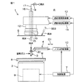
図1は、本発明の第1実施形態に係る基板処理装置1の概略構成を示す側面図である。図2は、本発明の第1実施形態に係る基板処理装置1の概略構成を示す平面図である。
基板処理装置1は、基板Wを1枚ずつ処理する枚葉式の基板処理装置である。基板処理装置1は、基板Wを水平に保持して回転させるスピンチャック2と、スピンチャック2に保持された基板Wの上面に向けて処理液を吐出するノズル3と、ノズル3を保持するノズルアーム4と、スピンチャック2の上方に配置された遮断板5と、これらの構成2〜5を収容する処理室6を区画する隔壁(図示せず)とを備えている。さらに、基板処理装置1は、基板処理装置1に備えられた装置の動作やバルブの開閉を制御する制御装置7を備えている。
Hereinafter, embodiments of the present invention will be described in detail with reference to the accompanying drawings.
FIG. 1 is a side view showing a schematic configuration of a
The
スピンチャック2は、基板Wを水平に保持して当該基板Wの中心を通る鉛直軸線まわりに回転可能な円盤状のスピンベース8と、このスピンベース8を鉛直軸線まわりに回転させるスピンモータ9とを含む。スピンチャック2は、基板Wを水平方向に挟んで当該基板Wを水平に保持する挟持式のチャックであってもよいし、非デバイス形成面である基板Wの裏面(下面)を吸着することにより当該基板Wを水平に保持するバキューム式のチャックであってもよい。第1実施形態では、スピンチャック2は、たとえば挟持式のチャックである。
The
ノズル3は、液体と気体とを衝突させることにより複数の液滴を生成し、生成された複数の液滴を基板Wに向けて吐出する二流体ノズルである。第1実施形態では、液体の一例である純水が、ノズル3に供給され、気体の一例である窒素ガスが、ノズル3に供給される。ノズル3は、その吐出口が下方に向けられた状態でスピンチャック2よりも上方に配置されている。ノズル3は、二流体ノズルに限らず、連続流の状態で処理液を吐出するストレートノズルであってもよいし、窒素ガスなどの気体を吐出するノズルであってもよい。
The nozzle 3 is a two-fluid nozzle that generates a plurality of droplets by causing a liquid and a gas to collide, and discharges the generated plurality of droplets toward the substrate W. In the first embodiment, pure water that is an example of a liquid is supplied to the nozzle 3, and nitrogen gas that is an example of a gas is supplied to the nozzle 3. The nozzle 3 is disposed above the
ノズル3は、ノズルアーム4の先端部20で保持されている。ノズルアーム4は、水平面に沿う長手方向D1に延びている。図2に示すように、ノズルアーム4の基端部21は、ノズル回転機構10に連結されている。ノズル回転機構10は、スピンチャック2の側方に設けられた鉛直なノズル回転軸線L1まわりに、ノズル3およびノズルアーム4を回転させる。ノズル回転機構10は、ノズル3がスピンチャック2の上方に位置している処理位置(図1に示す位置および図2において実線で示す位置)と、ノズル3がスピンチャック2の上方から退避している待機位置(図2において二点鎖線で示す位置)と、の間でノズル3およびノズルアーム4を水平に移動させる。待機位置には、処理液を受け止めるポッド11が配置されている。ポッド11は、上向きに開いた容器である。ポッド11は、ノズル3が待機位置に配置されているときに、ノズル3の下方に位置するように配置されている。
The nozzle 3 is held by the
遮断板5は、基板Wとほぼ同じ直径を有する円板状の部材である。遮断板5は、水平な姿勢で支軸12に支持されている。支軸12は、遮断板昇降機構13および遮断板回転機構14に連結されている。遮断板昇降機構13は、遮断板5の下面が基板Wの上面に近接している処理位置と、処理位置の上方に設けられた退避位置(図1に示す位置)との間で、遮断板5および支軸12を昇降させる。遮断板回転機構14は、基板Wの中心を通る鉛直軸線まわりに遮断板5および支軸12を回転させる。支軸12は、円筒状である。支軸12の内部空間は、遮断板5の中央部を鉛直方向に貫通する貫通孔15に接続されている。第1配管16は、支軸12内に挿入されており、第2配管17は、第1配管16に接続されている。第2配管17に介装された純水バルブ18が開かれると、第2配管17から第1配管16に純水が供給され、純水バルブ18が閉じられると、第1配管16への純水の供給が停止される。第1配管16に供給された純水は、中心軸ノズル19を構成する第1配管16の下端部から基板Wの上面中央部に向けて吐出される。
The blocking plate 5 is a disk-shaped member having substantially the same diameter as the substrate W. The blocking plate 5 is supported by the
中心軸ノズル19から基板Wに処理液を供給するときには、たとえば、制御装置7が、スピンモータ9を制御することにより、スピンチャック2に保持された基板Wを回転させる。そして、制御装置7は、遮断板5を処理位置に位置させた状態で、回転状態の基板Wの上面に向けて中心軸ノズル19から処理液を吐出させる。中心軸ノズル19から吐出された処理液は、基板Wの上面中央部に供給された後、基板Wの回転による遠心力によって基板Wの上面に沿って外方に広がる。これにより、基板Wの上面全域に処理液が供給され、基板Wが処理される。
When supplying the processing liquid from the
また、ノズル3から基板Wに処理液を供給するときには、たとえば、制御装置7が、スピンモータ9を制御することにより、スピンチャック2に保持された基板Wを回転させる。そして、制御装置7は、ノズル3を処理位置に位置させた状態で、回転状態の基板Wの上面に向けてノズル3から処理液を吐出させる。第1実施形態では、ノズル3が二流体ノズルであるので、複数の液滴が、ノズル3から基板Wの上面に向けて噴射される。これにより、基板Wの上面に処理液が供給され、基板Wが処理される。
When supplying the processing liquid from the nozzle 3 to the substrate W, for example, the
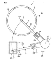
図3は、本発明の第1実施形態に係るノズルアーム4およびこれに関連する構成の側面図である。図4は、図3に示す矢印IVの方向から見たノズルアーム4の断面図である。図3は、ノズル3およびノズルアーム4が待機位置に配置されている状態を示している。
ノズルアーム4は、先端部20と基端部21とを含む棒状の部材である。すなわち、ノズルアーム4は、先端部20と、基端部21と、基端部21と先端部20とを接続する棒状のアーム部22とを含む。アーム部22は、長手方向D1に延びている。先端部20および基端部21は、それぞれ、アーム部22の一端部および他端部に結合されている。ノズル3は、先端部20に保持されている。先端部20は、基端部21から離れる方向に向かってアーム部22の一端部から下方に延びている。ノズル3は、柱状であり、鉛直な姿勢で先端部20に保持されている。ノズル3は、先端部20から下方に延びるノズル下部23を含む。ノズル下部23は、基端部21およびアーム部22よりも下方に配置されている。また、基端部21は、ボルト24によってベース25に取り付けられている。ノズル回転機構10の駆動力は、ベース25を介してノズルアーム4に伝達される。先端部20およびアーム部22は、処理位置においてスピンチャック2に保持された基板Wの上方に位置する部分である(図2参照)。
FIG. 3 is a side view of the nozzle arm 4 and the configuration related thereto according to the first embodiment of the present invention. 4 is a cross-sectional view of the nozzle arm 4 as seen from the direction of the arrow IV shown in FIG. FIG. 3 shows a state in which the nozzle 3 and the nozzle arm 4 are arranged at the standby position.
The nozzle arm 4 is a rod-shaped member including a
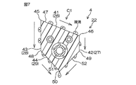
ノズルアーム4は、疎水性材料によって形成されている。疎水性材料としては、たとえば、ポリテトラフルオロエチレンなどのフッ素樹脂が挙げられる。図4に示すように、アーム部22は、上面26、右側面27、左側面28、およびV字状の下面29を含む五角形状の直交断面C1(長手方向D1に直交する断面)を有している。アーム部22の直交断面C1は、アーム部22の一端部からアーム部22の他端部まで一定である。すなわち、直交断面C1は、アーム部22の一端部からアーム部22の他端部まで同じ形で同じ大きさ(同形同大)である。アーム部22には、ノズルアーム4を補強する棒状の芯材30が埋め込まれている。芯材30は、たとえば、ステンレス鋼によって形成されている。さらに、アーム部22の内部には、ノズル3に液体を供給する液体供給管31と、ノズル3に気体を供給する気体供給管32とが差し込まれている。芯材30、液体供給管31、および気体供給管32は、アーム部22内で長手方向D1に延びている。図3に示すように、液体供給管31および気体供給管32は、アーム部22から先端部20側に突出しており、ノズル3に接続されている。
The nozzle arm 4 is made of a hydrophobic material. Examples of the hydrophobic material include fluororesins such as polytetrafluoroethylene. As shown in FIG. 4, the
基板処理装置1は、ノズルアーム4に純水を供給してノズルアーム4を洗浄する第1純水ノズル33(純水ノズル)および第2純水ノズル34と、ノズルアーム4に気体を供給してノズルアーム4に付着している純水を除去する第1気体ノズル35および第2気体ノズル36とをさらに含む。図3に示すように、第1純水ノズル33および第2純水ノズル34は、ノズルアーム4の基端部21の近傍に配置されている。第1純水ノズル33は、ノズルアーム4の上方に配置されており、第2純水ノズル34は、ノズルアーム4の下方に配置されている。さらに、図4に示すように、第1純水ノズル33および第2純水ノズル34は、直交断面C1の幅方向(長手方向D1に直交する水平な方向)に関する中心を通る鉛直な軸線CL1上に配置されている。第1純水ノズル33および第2純水ノズル34は、ノズルアーム4と共にノズル回転軸線L1まわりに水平に移動するように保持されている。
The
図3に示すように、第1純水ノズル33および第2純水ノズル34には共通の純水バルブ37を介して、洗浄液としての純水が供給される。すなわち、純水バルブ37が開かれると、第1純水ノズル33に純水が供給され、ノズルアーム4に向けて第1純水ノズル33から純水が吐出される。さらに、純水バルブ37が開かれると、第2純水ノズル34に純水が供給され、ノズルアーム4に向けて第2純水ノズル34から純水が吐出される。したがって、純水バルブ37が開かれると、第1純水ノズル33および第2純水ノズル34から純水が吐出される。
As shown in FIG. 3, pure water as a cleaning liquid is supplied to the first
第1純水ノズル33は、第1純水ノズル33からたとえば水平に純水が吐出されるように配置されている。第1純水ノズル33から吐出された純水は、ノズルアーム4に沿って長手方向D1に流れる。一方、第2純水ノズル34は、第2純水ノズル34からたとえば斜め上向きに純水が吐出されるように配置されている。第2純水ノズル34から吐出された純水は、ノズルアーム4の下部に供給される。そして、ノズルアーム4に供給された純水は、ノズルアーム4に沿って長手方向D1に流れる。
The 1st
また、図3に示すように、第1気体ノズル35および第2気体ノズル36は、ノズルアーム4よりも下方に配置されている。第1気体ノズル35は、ノズルアーム4の基端部21側に配置されており、第2気体ノズル36は、ノズルアーム4の先端部20側に配置されている。第1気体ノズル35は、平面視においてノズルアーム4に重なり合わないように配置されている(図2参照)。また、第2気体ノズル36は、ノズル下部23の近傍に配置されている。第2気体ノズル36は、ノズル下部23に対して水平方向に対向している。第1気体ノズル35および第2気体ノズル36は、それぞれ、待機位置に配置された第1ステー38および第2ステー39によって保持されている。したがって、ノズル3およびノズルアーム4がノズル回転軸線L1まわりに回転すると、第1気体ノズル35および第2気体ノズル36は、ノズル3およびノズルアーム4に対して相対移動する。
Further, as shown in FIG. 3, the
図3に示すように、第1気体ノズル35および第2気体ノズル36には共通の気体バルブ40を介して、気体の一例である窒素ガスが供給される。すなわち、気体バルブ40が開かれると、第1気体ノズル35に窒素ガスが供給され、ノズルアーム4に向けて第1気体ノズル35から窒素ガスが吐出される。さらに、気体バルブ40が開かれると、第2気体ノズル36に窒素ガスが供給され、ノズル3に向けて第2気体ノズル36の第2気体吐出口から窒素ガスが吐出される。したがって、気体バルブ40が開かれると、第1気体ノズル35および第2気体ノズル36から窒素ガスが吐出される。
As shown in FIG. 3, nitrogen gas, which is an example of gas, is supplied to the
第1気体ノズル35は、第1気体ノズル35からたとえば斜め上向きに窒素ガスが吐出されるように配置されている。第1気体ノズル35から吐出された窒素ガスは、ノズルアーム4の下部に吹き付けられる。そして、ノズルアーム4に吹き付けられた窒素ガスは、ノズルアーム4の下部に沿って長手方向D1に流れる。さらに、第1気体ノズル35およびノズルアーム4が平面視において重なり合わないように配置されているので、第1気体ノズル35から吐出された窒素ガスは、ノズルアーム4の下部に対して側方から吹き付けられる。一方、第2気体ノズル36は、第2気体ノズル36からたとえば水平に窒素ガスが吐出されるように配置されている。第2気体ノズル36から吐出された窒素ガスは、ノズル下部23に吹き付けられる。
The
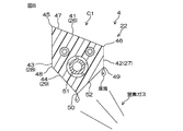
図5は、図4の一部を拡大した図である。以下では、ノズルアーム4の断面(アーム部22の直交断面C1)について詳細に説明する。
前述のように、直交断面C1は、たとえば、五角形状である。直交断面C1は、上部41、右側部42(側部、他方の側端)、左側部43(一方の側端)、および下部44を含む。上部41、右側部42、左側部43、および下部44は、それぞれ、上面26、右側面27、左側面28、および下面29の一部である。上部41は、水平面に対して傾斜している。右側部42および左側部43は、上下方向に延びている。下部44は、水平面に対して傾斜している。下部44は、たとえばV字状である。
FIG. 5 is an enlarged view of a part of FIG. Below, the cross section (the orthogonal cross section C1 of the arm part 22) of the nozzle arm 4 is demonstrated in detail.
As described above, the orthogonal cross section C1 has, for example, a pentagonal shape. The orthogonal cross section C <b> 1 includes an
上部41は、左端45(頂部)と、右端46と、左端45と右端46とを接続する上側傾斜部47とを含む。上部41の左端45は、直交断面C1において最も上に位置している。したがって、上部41の右端46は、上部41の左端45よりも下方に位置している。上側傾斜部47は、上部41の右端46に近づくほど下降するように連続的に傾斜している。すなわち、上側傾斜部47は、頂部としての上部41の左端45から右側部42の一部である上部41の右端46まで下降し続けている。上側傾斜部47の傾斜角度は、たとえば一定である。上側傾斜部47の傾斜角度は、一定に限らず、連続的に変化していてもよい。すなわち、上側傾斜部47は、第1実施形態のような直線であってもよいし、上または下に凸の曲線であってもよい。
The
また、下部44は、左端48と、右端49と、左端48と右端49との間に配置された下端50(底部)と、左端48と下端50とを接続する左側傾斜部51と、右端49と下端50とを接続する右側傾斜部52(下側傾斜部)とを含む。下端50は、直交断面C1において最も下に位置している。したがって、下部44の左端48および右端49は、下端50よりも上方に位置している。左側傾斜部51は、左側部43の一部である下部44の左端48から底部としての下端50まで下降し続けるように連続的に傾斜している。同様に、右側傾斜部52は、右側部42の一部である下部44の右端49から底部としての下端50まで下降し続けるように連続的に傾斜している。左側傾斜部51および右側傾斜部52の傾斜角度は、一定であってもよいし、連続的に変化していてもよい。さらに、左側傾斜部51の傾斜角度や変化の状態は、右側傾斜部52と同じであってもよいし、異なっていてもよい。下部44は、直交断面C1の幅(左右方向への長さ)が下端50に近づくほど減少するように傾斜している。
The
また、左側部43は、上部41の左端45から下部44の左端48まで下方に延びている。上部41の左端45、左側部43、および下部44の左端48は、直交断面C1において最も左側方に位置している。上部41の左端45は、上部41の一部であると共に、左側部43の一部でもある。同様に、下部44の左端48は、下部44の一部であると共に、左側部43の一部でもある。左側部43は、直交断面C1において最も側方に位置している一方の側端である。
The
また、右側部42は、上部41の右端46から下部44の右端49まで下方に延びている。上部41の右端46、右側部42、および下部44の右端49は、直交断面C1において最も右側方に位置している。上部41の右端46は、上部41の一部であると共に、右側部42の一部でもある。同様に、下部44の右端49は、下部44の一部であると共に、右側部42の一部でもある。右側部42は、直交断面C1において最も側方に位置している他方の側端である。すなわち、右側部42および左側部43は、軸線CL1に対して互いに反対側に配置された左右一対の側端である。
The
第1気体ノズル35は、ノズルアーム4の側方からノズルアーム4の下部に向けて気体を吐出するように構成されている。すなわち、第1気体ノズル35から吐出された窒素ガスは、ノズルアーム4の右側面27や下面29に対して右側方から吹き付けられる。前述のように、上側傾斜部47は、上部41の右端46に近づくほど下降するように傾斜している。したがって、上側傾斜部47は、第1気体ノズル35からの気体が吹き付けられる側に向かって下降している(図8参照)。
The
図6は、ノズル3およびノズルアーム4を洗浄するときの動作の一例について説明するための工程図である。図7は、ノズルアーム4に純水が供給されているときの純水の動きの一例について説明するための断面図である。図8は、ノズルアーム4に窒素ガスが供給されているときの純水の動きの一例について説明するための断面図である。以下では、図3を参照する。また、以下の説明では、図1、図6、図7および図8を適宜参照する。 FIG. 6 is a process diagram for explaining an example of an operation when the nozzle 3 and the nozzle arm 4 are cleaned. FIG. 7 is a cross-sectional view for explaining an example of the movement of pure water when pure water is supplied to the nozzle arm 4. FIG. 8 is a cross-sectional view for explaining an example of the movement of pure water when nitrogen gas is supplied to the nozzle arm 4. In the following, reference is made to FIG. In the following description, FIGS. 1, 6, 7, and 8 are referred to as appropriate.
ノズル3およびノズルアーム4の洗浄は、たとえば、スピンチャック2に基板Wが保持されていない状態で行われる。また、ノズル3およびノズルアーム4の洗浄では、最初に、たとえば第1純水ノズル33および第2純水ノズル34からノズルアーム4に向けて純水が吐出される(図6のステップS1、第1純水供給工程)。具体的には、制御装置7は、ノズル3およびノズルアーム4を待機位置に位置させた状態で、純水バルブ37を開いて、第1純水ノズル33および第2純水ノズル34から純水を吐出させる。
The nozzle 3 and the nozzle arm 4 are cleaned, for example, in a state where the substrate W is not held on the
第1純水ノズル33から吐出された純水の大部分は、アーム部22の上面26に供給され、第1純水ノズル33から吐出された純水の一部は、アーム部22の右側面27および左側面28に供給される。アーム部22の上面26が水平面に対して傾斜しているので、アーム部22の上面26に供給された純水は、先端部20に向かって長手方向D1に移動しながら、上面26に沿って下方に流れる(図7参照)。そして、上部41の右端46に達した純水は、上部41の右端46から側方に飛散したり、右側面27に沿って下方に流れたりする。また、右側面27および左側面28に供給された純水は、先端部20に向かって長手方向D1に移動しながら、右側面27または左側面28に沿って下方に流れる。そして、図7に示すように、右側面27の下端(下部44の右端49)および左側面28の下端(下部44の左端48)に達した純水は、右側面27または左側面28から落下したり、下面29に沿って下方に流れたりする。
Most of the pure water discharged from the first
一方、第2純水ノズル34から吐出された純水の大部分は、アーム部22の下面29に供給され、第2純水ノズル34から吐出された純水の一部は、アーム部22の右側面27および左側面28に供給される。前述のように、右側面27および左側面28に供給された純水は、右側面27または左側面28から落下したり、下面29に沿って下方に流れたりする。その一方で、アーム部22の下面29が水平面に対して傾斜しているので、アーム部22の下面29に供給された純水は、先端部20に向かって長手方向D1に移動しながら、下面29に沿って下方に流れる(図7参照)。つまり、アーム部22の下面29に供給された純水は、下端50に向かって移動するように下面29に沿って流れる。そして、下端50に達した純水の一部は、ノズルアーム4から落下する。
On the other hand, most of the pure water discharged from the second
このように、第1純水ノズル33および第2純水ノズル34から吐出された純水は、アーム部22の上面26、右側面27、左側面28、および下面29に供給される。これにより、アーム部22に付着しているパーティクルなどの異物や処理液が純水によって洗い流される。また、第1純水ノズル33および第2純水ノズル34からアーム部22に供給された純水は、先端部20に向かって長手方向D1に流れる。そして、先端部20の近傍に達した純水は、アーム部22から先端部20に移動し、先端部20やノズル3に沿って下方に流れる。これにより、先端部20やノズル3に付着している異物等が純水によって洗い流される。そして、先端部20やノズル3から落下した純水は、ポッド11によって受け止められる。
As described above, the pure water discharged from the first
次に、第1気体ノズル35および第2気体ノズル36からノズル3およびノズルアーム4に向けて窒素ガスが吐出される(図6のステップS2、第1気体供給工程)。具体的には、制御装置7は、ノズル3およびノズルアーム4を待機位置に位置させた状態で、気体バルブ40を開いて、第1気体ノズル35および第2気体ノズル36から窒素ガスを吐出させる。
Next, nitrogen gas is discharged from the
第1気体ノズル35から吐出された窒素ガスの大部分は、アーム部22の下面29に吹き付けられ、第1気体ノズル35から吐出された窒素ガスの一部は、アーム部22の右側面27および左側面28に吹き付けられる(図8参照)。アーム部22の下面29に吹き付けられた窒素ガスは、下面29に沿って先端部20の方へ長手方向D1に流れる。また、アーム部22の右側面27および左側面28に吹き付けられた窒素ガスは、右側面27または左側面28に沿って先端部20の方へ長手方向D1に流れる。これにより、アーム部22の下面29、右側面27、および左側面28に付着している純水が、窒素ガスによって吹き飛ばされ除去される。
Most of the nitrogen gas discharged from the
一方、第2気体ノズル36から吐出された窒素ガスの大部分は、ノズル下部23に吹き付けられる。また、第1気体ノズル35からアーム部22に向けて吐出され、先端部20の近傍に達した窒素ガスは、先端部20やノズル3に沿って流れる。したがって、先端部20には、第1気体ノズル35から吐出された窒素ガスが吹き付けられ、ノズル3には、第1気体ノズル35および第2気体ノズル36から吐出された窒素ガスが吹き付けられる。これにより、先端部20やノズル3に付着している純水が吹き飛ばされ除去される。
On the other hand, most of the nitrogen gas discharged from the
このように、第1気体ノズル35から窒素ガスが吐出されることにより、アーム部22の下面29、右側面27、および左側面28から純水が除去される。第1気体ノズル35から吐出された窒素ガスは、アーム部22の上面26に殆ど供給されないが、アーム部22の上面26に供給された純水は、上面26の傾斜によって流れ落ちることにより、上面26から除去される。したがって、アーム部22の下面29、右側面27、および左側面28から純水を除去することにより、アーム部22全体から純水を除去することができる。さらに、第1気体ノズル35から吐出された窒素ガスは、ノズル3や先端部20にも供給されるので、ノズル3およびノズルアーム4に付着している純水を効率的に除去することができる。
Thus, pure water is removed from the
次に、中心軸ノズル19からノズル3およびノズルアーム4の先端部20に向けて純水が吐出される(図6のステップS3、第2純水供給工程)。具体的には、制御装置7は、遮断板5を待機位置に位置させた状態で、ノズル回転機構10を制御して、ノズル3およびノズルアーム4を処理位置に移動させる(図1参照)。すなわち、制御装置7は、ノズル3を中心軸ノズル19の下方に移動させる。そして、制御装置7は、ノズル3が中心軸ノズル19の下方に位置する状態で、純水バルブ18を開いて、中心軸ノズル19からノズル3に向けて純水を吐出させる。
Next, pure water is discharged from the
中心軸ノズル19から吐出された純水の大部分は、ノズル3およびノズルアーム4の先端部20に供給される。すなわち、ノズル3および先端部20には、第1純水ノズル33および第2純水ノズル34からだけでなく、中心軸ノズル19からも純水が供給される。これにより、ノズル3および先端部20に純水が十分に供給される。特に、第1純水ノズル33および第2純水ノズル34からの純水が十分に供給されない範囲(ノズル3の凹部や、ノズルアーム4の湾曲部)にも確実に純水が供給される。これにより、ノズル3および先端部20に付着している異物や処理液が確実に除去される。
Most of the pure water discharged from the
次に、第1気体ノズル35および第2気体ノズル36からノズル3およびノズルアーム4に向けて窒素ガスが吐出される(図6のステップS4、第2気体供給工程)。具体的には、制御装置7は、遮断板5を待機位置に位置させた状態で、ノズル回転機構10を制御して、ノズル3およびノズルアーム4を待機位置に移動させる。そして、制御装置7は、ノズル3およびノズルアーム4を待機位置に位置させた状態で、気体バルブ40を開いて、第1気体ノズル35および第2気体ノズル36から窒素ガスを吐出させる。前述のように、ノズル3、先端部20、およびアーム部22に付着している純水は、第1気体ノズル35および第2気体ノズル36から吐出された窒素ガスによって除去される。これにより、ノズル3およびノズルアーム4が乾燥し、ノズル3およびノズルアーム4の洗浄が完了する。
Next, nitrogen gas is discharged from the
以上のように第1実施形態では、ノズル3を保持するノズルアーム4が、水平面に沿う長手方向D1に延びている。アーム部22の直交断面C1は、頂部(左端45)から右側部42まで下降し続けている上側傾斜部47を含む。上側傾斜部47が下降し続けているから、上側傾斜部47に処理液が付着したとしても、この処理液は、上側傾斜部47に沿って下に流れる。そして、この処理液は、ノズルアーム4から落下し除去される。すなわち、ノズルアーム4に処理液が付着したとしても、この処理液は、短時間でノズルアーム4から除去される。したがって、ノズルアーム4に対する処理液の残留量を低減することができる。
As described above, in the first embodiment, the nozzle arm 4 that holds the nozzle 3 extends in the longitudinal direction D1 along the horizontal plane. The orthogonal cross section C <b> 1 of the
また第1実施形態では、直交断面C1が、右側部42から底部(下端44)まで下降し続けている右側傾斜部52と、左側部43から底部まで下降し続けている左側傾斜部51とを含む。右側傾斜部52および左側傾斜部51が底部まで下降し続けているから、右側傾斜部52および左側傾斜部51に処理液が付着したとしても、この処理液は、右側傾斜部52および左側傾斜部51に沿って下に流れる。そして、この処理液は、ノズルアーム4から落下し除去される。したがって、ノズルアーム4に対する処理液の残留量を低減することができる。
In the first embodiment, the right-side
また第1実施形態では、直交断面C1の一方の側端が、頂部(左端45)を含み、右側部42が、直交断面C1の他方の側端を含む。上側傾斜部47は、頂部から右側部42まで延びている。したがって、上側傾斜部47は、一方の側端から他方の側端まで延びている。すなわち、直交断面C1の上部41は、一方の側端から他方の側端まで延びており、他方の側端に近づくほど下降している。そのため、直交断面C1の上部41に付着した処理液は、共通の側端(他方の側端)に向かって流れ落ちる。これにより、直交断面C1の上部41に付着している液滴同士を結合させて、その自重によって落下させることができる。したがって、ノズルアーム4に対する処理液の残留量を低減することができる。
In the first embodiment, one side end of the orthogonal cross section C1 includes the top portion (left end 45), and the
また第1実施形態では、第1気体ノズル35から吐出された窒素ガスがノズルアーム4の下部に吹き付けられる。前述のように、ノズルアーム4に付着した処理液は、ノズルアーム4に沿って下に流れる。すなわち、ノズルアーム4に付着した処理液は、ノズルアーム4の下部に集まる。この処理液が集まる位置に窒素ガスが吹き付けられる。これにより、ノズルアーム4に付着している処理液を吹き飛ばして効率的に除去することができる。したがって、ノズルアーム4に対する処理液の残留量を低減することができる。
In the first embodiment, nitrogen gas discharged from the
また第1実施形態では、第1気体ノズル35から吐出された窒素ガスがノズルアーム4に沿って長手方向D1に流れる。したがって、第1気体ノズル35からノズルアーム4に窒素ガスが吹き付けられる範囲が広がる。これにより、より広い範囲から処理液を除去することができる。したがって、ノズルアーム4に対する処理液の残留量を低減することができる。
In the first embodiment, the nitrogen gas discharged from the
また第1実施形態では、第1気体ノズル35から吐出された窒素ガスが、ノズルアーム4の下部に対して側方から吹き付けられる。上側傾斜部47は、第1気体ノズル35からの窒素ガスが吹き付けられる側に向かって下降している。したがって、上側傾斜部47に付着した処理液は、第1気体ノズル35からの窒素ガスが吹き付けられる側に向かって流れ落ちる。言い換えると、第1気体ノズル35から吐出された窒素ガスは、上側傾斜部47に付着した処理液が集まる位置に吹き付けられる。したがって、上側傾斜部47に付着した処理液を効率的に除去することができる。
In the first embodiment, the nitrogen gas discharged from the
また第1実施形態では、ノズルアーム4が疎水性を有している。したがって、ノズルアーム4が親水性の場合に比べて、ノズルアーム4に付着した処理液は、短時間でかつ小さい力でノズルアーム4から除去される。さらに、処理液がはじかれるから、ノズルアーム4に保持される処理液の量を低減することができる。したがって、ノズルアーム4に対する処理液の残留量を一層低減できる。 In the first embodiment, the nozzle arm 4 is hydrophobic. Therefore, compared with the case where the nozzle arm 4 is hydrophilic, the treatment liquid adhering to the nozzle arm 4 is removed from the nozzle arm 4 in a short time and with a small force. Furthermore, since the processing liquid is repelled, the amount of the processing liquid held in the nozzle arm 4 can be reduced. Therefore, the residual amount of the processing liquid with respect to the nozzle arm 4 can be further reduced.
また第1実施形態では、第1純水ノズル33から吐出された純水がノズルアーム4の上面26に供給される。これにより、ノズルアーム4の上面26に付着しているパーティクル等の異物や処理液が洗い流される。したがって、ノズルアーム4の上面26に付着している異物や処理液が基板W上に落下して、基板Wが汚染されることを抑制または防止できる。さらに、前述のように、ノズルアーム4に供給された純水は、ノズルアーム4に沿って流れ落ちることによりノズルアーム4から短時間で除去されるので、ノズルアーム4への純水の供給が終了した後に、ノズルアーム4から基板Wに純水が落下することを抑制または防止することができる。
In the first embodiment, pure water discharged from the first
また第1実施形態では、第2気体ノズル36から吐出された窒素ガスが、ノズルアーム4よりも下方に位置するノズル下部23に吹き付けられる。ノズル下部23は、ノズルアーム4よりも下方に配置されているから、ノズル3の外表面に付着した処理液や、ノズルアーム4を伝ってノズル3に移動した処理液は、ノズル下部23に向かって流れ落ちる。したがって、第2気体ノズル36から吐出された窒素ガスは、処理液が集まる位置に吹き付けられる。そのため、処理液を効率的に除去することができる。
In the first embodiment, the nitrogen gas discharged from the
また第1実施形態では、第1気体ノズル35から吐出された窒素ガスは、ノズルアーム4に沿って基端部21から先端部20に向かう方向D2(図3参照)に流れる。同様に、第2気体ノズル36から吐出された窒素ガスは、ノズル下部23に沿って基端部21から先端部20に向かう方向D2に流れる。すなわち、各気体ノズル35、36から吐出された窒素ガスは、同じ向きに流れる。したがって、第1気体ノズル35から吐出された窒素ガスと、第2気体ノズル36から吐出された窒素ガスとが衝突して、各気体ノズル35、36から吐出された窒素ガスの勢いが弱まることを抑制または防止することができる。これにより、ノズル3およびノズルアーム4に付着している処理液を確実に除去することができる。
In the first embodiment, the nitrogen gas discharged from the
また第1実施形態では、ノズル回転機構10の駆動力がノズルアーム4に伝達されることにより、ノズルアーム4が処理位置と待機位置との間で移動する。第1気体ノズル35から吐出された窒素ガスは、待機位置に位置しているノズルアーム4の下部に吹き付けられる。したがって、第1気体ノズル35をノズルアーム4の待機位置に配置することができる。すなわち、第1気体ノズル35は、ノズルアーム4と共に移動するように構成されていなくてもよい。したがって、ノズルアーム4を含む可動部の大型化を抑制または防止することができる。
In the first embodiment, the driving force of the
また第1実施形態では、処理位置においてスピンチャック2に保持された基板Wの上方に位置している部分、すなわち、アーム部22が、直交断面C1を有している。したがって、アーム部22に処理液が付着したとしても、この処理液は、短時間で除去される。そのため、基板W上でノズルアーム4を移動させたとしても、ノズルアーム4から基板Wに処理液が落下することを確実に抑制または防止できる。これにより、基板Wの汚染や品質低下を抑制または防止できる。
In the first embodiment, the portion positioned above the substrate W held by the
この発明の実施の形態の説明は以上であるが、この発明は、前述の第1実施形態の内容に限定されるものではなく、請求項記載の範囲内において種々の変更が可能である。
たとえば、前述の第1実施形態では、直交断面C1が、図5に示す五角形状である場合について説明した。しかし、直交断面C1の形状は、図5の上下が反転された形状であってもよい。すなわち、直交断面C1の上部が、倒立V字状で、直交断面C1の下部が、一方の側端から他方の側端まで延びる斜線であってもよい。さらに、直交断面C1は、五角形以外の多角形であってもよい。
Although the embodiment of the present invention has been described above, the present invention is not limited to the contents of the first embodiment described above, and various modifications can be made within the scope of the claims.
For example, in the first embodiment described above, the case where the orthogonal cross section C1 has the pentagonal shape shown in FIG. 5 has been described. However, the shape of the orthogonal cross section C1 may be a shape in which the top and bottom of FIG. That is, the upper part of the orthogonal cross section C1 may be an inverted V shape, and the lower part of the orthogonal cross section C1 may be a diagonal line extending from one side end to the other side end. Further, the orthogonal cross section C1 may be a polygon other than a pentagon.
具体的には、たとえば図9に示すノズルアーム204のように、ノズルアーム204の直交断面C201は、三角形状であってもよい。直交断面C201は、頂部245と、側部246と、上側傾斜部247とを含む。さらに、直交断面C201は、底部250と、下側傾斜部252とを含む。
また、図10に示すノズルアーム304のように、ノズルアーム304の直交断面C301は、四角形状であってもよい。直交断面C301は、頂部345と、側部346と、上側傾斜部347とを含む。さらに、直交断面C301は、底部350と、下側傾斜部352とを含む。
Specifically, for example, like the
Further, like the
また、前述の第1実施形態では、直交断面C1が、複数の直線によって区画されている場合について説明したが、直交断面C1は、直線および曲線を含んでいてもよいし、曲線によって区画されていてもよい。
具体的には、たとえば図11に示すノズルアーム404のように、ノズルアーム404の直交断面C401は、下側に凸の曲線と、水平面に対して傾斜している直線とによって区画されていてもよい。直交断面C401は、頂部445と、側部446と、上側傾斜部447とを含む。さらに、直交断面C401は、底部450と、下側傾斜部452とを含む。
In the first embodiment, the case where the orthogonal cross section C1 is defined by a plurality of straight lines has been described. However, the orthogonal cross section C1 may include a straight line and a curve, or may be defined by a curve. May be.
Specifically, for example, like the
また、前述の第1実施形態では、アーム部22が、アーム部22の一端部からアーム部22の他端部まで一定の断面(直交断面C1)を有している場合について説明した。しかし、アーム部22の断面は、変化していてもよい。
具体的には、任意の2つの位置におけるアーム部22の断面が相似(同形)であり、アーム部22の断面積(大きさ)が連続的に変化していてもよい。この場合、アーム部22の断面積は、アーム部22の一端部(先端部20側の端部)に近づくほど減少していてもよい。また、アーム部22の断面形状(直交断面C1の形状)は、アーム部22の一端部に近づくに従って連続的に変化していてもよい。この場合、アーム部22の断面積は、一定であってもよいし、アーム部22の一端部に近づくほど減少していてもよい。
In the first embodiment described above, the case where the
Specifically, the cross section of the
また、前述の第1実施形態では、第1純水ノズル33および第2純水ノズル34からノズルアーム4に純水が供給される場合について説明した。しかし、第1純水ノズル33および第2純水ノズル34以外のノズルからノズルアーム4に純水が供給されてもよい。
具体的には、遮断板5の上面に純水を供給する純水ノズル553(図1参照)が設けられていてもよい。この場合、制御装置7は、遮断板回転機構14を制御することにより遮断板5を回転させながら、回転状態の遮断板5の上面に向けて純水ノズル553から純水を吐出させてもよい。純水ノズル553から吐出された純水は、遮断板5の上面に供給され、遮断板5の回転による遠心力によって遮断板5の周囲に振り切られる。したがって、遮断板5から振り切られた純水は、処理室6を区画する隔壁(図示せず)に衝突して跳ね返る。そして、跳ね返った純水がノズルアーム4に供給される。これにより、ノズルアーム4に付着している異物や処理液が洗い流される。
In the first embodiment described above, the case where pure water is supplied from the first
Specifically, a pure water nozzle 553 (see FIG. 1) for supplying pure water may be provided on the upper surface of the blocking plate 5. In this case, the
また、前述の第1実施形態では、ノズル3を保持する先端部20がノズルアーム4に設けられている場合について説明した。しかし、先端部20が設けられておらず、アーム部22の一端部にノズル3が保持されていてもよい。すなわち、アーム部22の一端部が、ノズル3を保持する先端部であってもよい。
また、前述の第1実施形態では、第1気体ノズル35および第2気体ノズル36から吐出される気体が窒素ガスである場合について説明した。しかし、第1気体ノズル35および第2気体ノズル36から吐出される気体は、窒素ガスに限らず、アルゴンガスなどの窒素ガス以外の不活性ガスであってもよいし、乾燥空気や、清浄空気であってもよい。
Further, in the first embodiment described above, the case where the
In the first embodiment described above, the case where the gas discharged from the
また、前述の第1実施形態では、第1純水ノズル33および第2気体ノズル36から水平に流体(純水または窒素ガス)が吐出され、第2純水ノズル34および第1気体ノズル35から斜め上向きに流体が吐出される場合について説明した。しかし、第1純水ノズル33および第2気体ノズル36からの流体の吐出方向は、斜め上向きまたは斜め下向きであってもよい。また、第2純水ノズル34および第1気体ノズル35からの純水の吐出方向は、水平方向であってもよい。
In the first embodiment described above, fluid (pure water or nitrogen gas) is discharged horizontally from the first
また、前述の第1実施形態では、共通の純水バルブ37を介して第1純水ノズル33および第2純水ノズル34に純水が供給され、共通の気体バルブ40を介して第1気体ノズル35および第2気体ノズル36に窒素ガスが供給される場合について説明した。しかし、別々のバルブを介して第1純水ノズル33および第2純水ノズル34に純水が供給されてもよい。同様に、別々のバルブを介して第1気体ノズル35および第2気体ノズル36に窒素ガスが供給されてもよい。
In the first embodiment, pure water is supplied to the first
その他、特許請求の範囲に記載された事項の範囲で種々の設計変更を施すことが可能である。 In addition, various design changes can be made within the scope of matters described in the claims.
1 基板処理装置
2 スピンチャック(基板保持手段)
3 ノズル
4 ノズルアーム
10 ノズル回転機構(移動手段)
20 先端部
21 基端部
22 アーム部(ノズルアームの少なくとも一部)
23 ノズル下部
26 ノズルアームの上面
33 第1純水ノズル(純水ノズル)
35 第1気体ノズル
36 第2気体ノズル
42 右側部(側部、他方の側端)
43 左側部(一方の側端)
45 左端(頂部)
47 上側傾斜部
50 下端(底部)
52 右側傾斜部(下側傾斜部)
204 ノズルアーム
245 頂部
246 側部
247 上側傾斜部
250 底部
252 下側傾斜部
304 ノズルアーム
345 頂部
346 側部
347 上側傾斜部
350 底部
352 下側傾斜部
404 ノズルアーム
445 頂部
446 側部
447 上側傾斜部
450 底部
452 下側傾斜部
C1 直交断面
C201 直交断面
C301 直交断面
C401 直交断面
D1 長手方向
D2 基端部から先端部に向かう方向
W 基板
1.
3 Nozzle 4
20
23 Nozzle
35
43 Left side (one side edge)
45 Left edge (top)
47 Upper inclined
52 Right slope (lower slope)
204
Claims (12)
前記ノズルを保持しており、水平面に沿う長手方向に延びているノズルアームと、を含み、
前記長手方向に直交する、前記ノズルアームの少なくとも一部の直交断面は、前記直交断面において最も上に位置している頂部と、前記頂部より側方に位置している側部と、前記頂部から前記側部まで下降し続けている上側傾斜部と、を含む、基板処理装置。 A nozzle for discharging a processing fluid for processing the substrate;
A nozzle arm holding the nozzle and extending in a longitudinal direction along a horizontal plane,
An orthogonal cross section of at least a part of the nozzle arm, which is orthogonal to the longitudinal direction, includes a top portion that is located at the top of the orthogonal cross section, a side portion that is located laterally from the top portion, and the top portion. And an upper inclined portion that continues to descend to the side portion.
一方の側端は、前記頂部を含み、前記側部は、他方の側端を含み、
前記上側傾斜部は、前記一方の側端から前記他方の側端まで下降し続けている、請求項1または2記載の基板処理装置。 The orthogonal cross section includes a pair of left and right side edges that are located most laterally in the orthogonal cross section,
One side end includes the top, and the side includes the other side end,
The substrate processing apparatus according to claim 1, wherein the upper inclined portion continues to descend from the one side end to the other side end.
前記上側傾斜部は、前記第1気体ノズルからの気体が吹き付けられる側に向かって下降している、請求項4または5記載の基板処理装置。 The first gas nozzle is configured to discharge gas from the side of the nozzle arm toward the lower portion of the nozzle arm,
The substrate processing apparatus according to claim 4, wherein the upper inclined portion descends toward a side to which gas from the first gas nozzle is blown.
前記基板処理装置は、前記ノズル下部に向けて気体を吐出する第2気体ノズルをさらに含む、請求項1〜8のいずれか一項に記載の基板処理装置。 The nozzle includes a lower nozzle portion disposed below the nozzle arm,
The said substrate processing apparatus is a substrate processing apparatus as described in any one of Claims 1-8 which further contains the 2nd gas nozzle which discharges gas toward the said nozzle lower part.
前記第1気体ノズルは、前記第1気体ノズルから吐出された気体が前記基端部から前記先端部に向かう方向に流れるように構成されており、
前記第2気体ノズルは、前記第2気体ノズルから吐出された気体が前記基端部から前記先端部に向かう方向に流れるように構成されている、請求項9記載の基板処理装置。 The nozzle arm is a rod-shaped member including a distal end portion that holds the nozzle and a proximal end portion,
The first gas nozzle is configured such that the gas discharged from the first gas nozzle flows in a direction from the base end portion toward the tip end portion,
The substrate processing apparatus according to claim 9, wherein the second gas nozzle is configured such that the gas discharged from the second gas nozzle flows in a direction from the base end portion toward the tip end portion.
前記ノズルが前記基板保持手段に保持された基板の上方に位置している処理位置と、前記ノズルが前記基板保持手段に保持された基板の上方から退避している待機位置との間で前記ノズルアームを移動させる移動手段と、をさらに含み、
前記第1気体ノズルは、前記待機位置に位置している前記ノズルアームの下部に向けて気体を吐出するように構成されている、請求項1〜10のいずれか一項に記載の基板処理装置。 Substrate holding means for holding the substrate;
The nozzle between a processing position where the nozzle is located above the substrate held by the substrate holding means and a standby position where the nozzle is retracted from above the substrate held by the substrate holding means Moving means for moving the arm, and
The substrate processing apparatus according to claim 1, wherein the first gas nozzle is configured to discharge a gas toward a lower portion of the nozzle arm located at the standby position. .
Priority Applications (3)
| Application Number | Priority Date | Filing Date | Title |
|---|---|---|---|
| JP2011045219A JP5734705B2 (en) | 2011-03-02 | 2011-03-02 | Substrate processing equipment |
| KR1020110093580A KR101221162B1 (en) | 2011-03-02 | 2011-09-16 | Substrate treatment apparatus |
| TW100134597A TWI434335B (en) | 2011-03-02 | 2011-09-26 | Substrate treatment apparatus |
Applications Claiming Priority (1)
| Application Number | Priority Date | Filing Date | Title |
|---|---|---|---|
| JP2011045219A JP5734705B2 (en) | 2011-03-02 | 2011-03-02 | Substrate processing equipment |
Publications (2)
| Publication Number | Publication Date |
|---|---|
| JP2012182371A true JP2012182371A (en) | 2012-09-20 |
| JP5734705B2 JP5734705B2 (en) | 2015-06-17 |
Family
ID=47013309
Family Applications (1)
| Application Number | Title | Priority Date | Filing Date |
|---|---|---|---|
| JP2011045219A Expired - Fee Related JP5734705B2 (en) | 2011-03-02 | 2011-03-02 | Substrate processing equipment |
Country Status (3)
| Country | Link |
|---|---|
| JP (1) | JP5734705B2 (en) |
| KR (1) | KR101221162B1 (en) |
| TW (1) | TWI434335B (en) |
Cited By (6)
| Publication number | Priority date | Publication date | Assignee | Title |
|---|---|---|---|---|
| JP2016082177A (en) * | 2014-10-22 | 2016-05-16 | 東京エレクトロン株式会社 | Substrate liquid processing device |
| JP2018129438A (en) * | 2017-02-09 | 2018-08-16 | 東京エレクトロン株式会社 | Liquid processing device |
| CN110137107A (en) * | 2015-02-12 | 2019-08-16 | 株式会社思可林集团 | Substrate board treatment, base plate processing system and substrate processing method using same |
| US10661411B2 (en) | 2014-11-20 | 2020-05-26 | Ebara Corporation | Apparatus for cleaning a polishing surface, polishing apparatus, and method of manufacturing an apparatus for cleaning a polishing surface |
| JP2021002612A (en) * | 2019-06-24 | 2021-01-07 | 株式会社荏原製作所 | Cover for rocking component of substrate processing device, rocking component of substrate processing device, and substrate processing device |
| WO2023042487A1 (en) * | 2021-09-16 | 2023-03-23 | 株式会社Screenホールディングス | Substrate processing device and substrate processing method |
Citations (11)
| Publication number | Priority date | Publication date | Assignee | Title |
|---|---|---|---|---|
| JPH0734982U (en) * | 1993-12-07 | 1995-06-27 | シチズン時計株式会社 | Washing basket |
| JPH07254583A (en) * | 1994-03-16 | 1995-10-03 | Hitachi Ltd | Method and apparatus for cleaning |
| JPH10275846A (en) * | 1997-03-31 | 1998-10-13 | Dainippon Screen Mfg Co Ltd | Substrate-holding member and substrate-treating device using the same |
| JP2001053046A (en) * | 1999-08-13 | 2001-02-23 | Furontekku:Kk | Nozzle and nozzle device for wet treatment and wet treatment apparatus |
| JP2003168668A (en) * | 2001-12-04 | 2003-06-13 | Tokyo Electron Ltd | Substrate-treating apparatus and substrate-treating method |
| JP2004267870A (en) * | 2003-03-06 | 2004-09-30 | Tokyo Electron Ltd | Process liquid feed nozzle and process liquid feeder, and method for washing nozzle |
| JP2004356517A (en) * | 2003-05-30 | 2004-12-16 | Ebara Corp | Method and device for substrate washing |
| JP2006026609A (en) * | 2004-07-21 | 2006-02-02 | Tokyo Electron Ltd | Cleaning treatment method and apparatus therefor |
| JP2007168039A (en) * | 2005-12-22 | 2007-07-05 | Ebara Corp | Polishing surface washing mechanism of polishing table and polishing device |
| WO2007132609A1 (en) * | 2006-05-15 | 2007-11-22 | Tokyo Electron Limited | Substrate processing method, substrate processing apparatus and recording medium |
| JP2009212335A (en) * | 2008-03-05 | 2009-09-17 | Tokyo Electron Ltd | Conveyor arm cleaning device, conveyor arm cleaning method, program, and computer storage medium |
Family Cites Families (3)
| Publication number | Priority date | Publication date | Assignee | Title |
|---|---|---|---|---|
| KR20030050796A (en) * | 2001-12-19 | 2003-06-25 | 삼성전자주식회사 | an apparatus for polishing semiconductor wafer |
| JP4494840B2 (en) | 2003-06-27 | 2010-06-30 | 大日本スクリーン製造株式会社 | Foreign matter removing apparatus, substrate processing apparatus, and substrate processing method |
| KR20080005808A (en) * | 2006-07-10 | 2008-01-15 | 삼성전자주식회사 | Apparatus for fabricating semiconductor device preventing particle of chamber |
-
2011
- 2011-03-02 JP JP2011045219A patent/JP5734705B2/en not_active Expired - Fee Related
- 2011-09-16 KR KR1020110093580A patent/KR101221162B1/en active IP Right Grant
- 2011-09-26 TW TW100134597A patent/TWI434335B/en not_active IP Right Cessation
Patent Citations (11)
| Publication number | Priority date | Publication date | Assignee | Title |
|---|---|---|---|---|
| JPH0734982U (en) * | 1993-12-07 | 1995-06-27 | シチズン時計株式会社 | Washing basket |
| JPH07254583A (en) * | 1994-03-16 | 1995-10-03 | Hitachi Ltd | Method and apparatus for cleaning |
| JPH10275846A (en) * | 1997-03-31 | 1998-10-13 | Dainippon Screen Mfg Co Ltd | Substrate-holding member and substrate-treating device using the same |
| JP2001053046A (en) * | 1999-08-13 | 2001-02-23 | Furontekku:Kk | Nozzle and nozzle device for wet treatment and wet treatment apparatus |
| JP2003168668A (en) * | 2001-12-04 | 2003-06-13 | Tokyo Electron Ltd | Substrate-treating apparatus and substrate-treating method |
| JP2004267870A (en) * | 2003-03-06 | 2004-09-30 | Tokyo Electron Ltd | Process liquid feed nozzle and process liquid feeder, and method for washing nozzle |
| JP2004356517A (en) * | 2003-05-30 | 2004-12-16 | Ebara Corp | Method and device for substrate washing |
| JP2006026609A (en) * | 2004-07-21 | 2006-02-02 | Tokyo Electron Ltd | Cleaning treatment method and apparatus therefor |
| JP2007168039A (en) * | 2005-12-22 | 2007-07-05 | Ebara Corp | Polishing surface washing mechanism of polishing table and polishing device |
| WO2007132609A1 (en) * | 2006-05-15 | 2007-11-22 | Tokyo Electron Limited | Substrate processing method, substrate processing apparatus and recording medium |
| JP2009212335A (en) * | 2008-03-05 | 2009-09-17 | Tokyo Electron Ltd | Conveyor arm cleaning device, conveyor arm cleaning method, program, and computer storage medium |
Cited By (11)
| Publication number | Priority date | Publication date | Assignee | Title |
|---|---|---|---|---|
| JP2016082177A (en) * | 2014-10-22 | 2016-05-16 | 東京エレクトロン株式会社 | Substrate liquid processing device |
| US10661411B2 (en) | 2014-11-20 | 2020-05-26 | Ebara Corporation | Apparatus for cleaning a polishing surface, polishing apparatus, and method of manufacturing an apparatus for cleaning a polishing surface |
| CN110137107A (en) * | 2015-02-12 | 2019-08-16 | 株式会社思可林集团 | Substrate board treatment, base plate processing system and substrate processing method using same |
| CN110137107B (en) * | 2015-02-12 | 2024-04-02 | 株式会社思可林集团 | Substrate processing apparatus, substrate processing system, and substrate processing method |
| JP2018129438A (en) * | 2017-02-09 | 2018-08-16 | 東京エレクトロン株式会社 | Liquid processing device |
| CN108417510A (en) * | 2017-02-09 | 2018-08-17 | 东京毅力科创株式会社 | Liquid handling device |
| US11322373B2 (en) | 2017-02-09 | 2022-05-03 | Tokyo Electron Limited | Liquid processing apparatus |
| JP2021002612A (en) * | 2019-06-24 | 2021-01-07 | 株式会社荏原製作所 | Cover for rocking component of substrate processing device, rocking component of substrate processing device, and substrate processing device |
| JP7186671B2 (en) | 2019-06-24 | 2022-12-09 | 株式会社荏原製作所 | Cover for rocking part of substrate processing apparatus, rocking part of substrate processing apparatus, and substrate processing apparatus |
| US11626299B2 (en) | 2019-06-24 | 2023-04-11 | Ebara Corporation | Cover for swing member of substrate processing apparatus, swing member of substrate processing apparatus, and substrate processing apparatus |
| WO2023042487A1 (en) * | 2021-09-16 | 2023-03-23 | 株式会社Screenホールディングス | Substrate processing device and substrate processing method |
Also Published As
| Publication number | Publication date |
|---|---|
| KR101221162B1 (en) | 2013-01-21 |
| TW201237950A (en) | 2012-09-16 |
| KR20120100685A (en) | 2012-09-12 |
| JP5734705B2 (en) | 2015-06-17 |
| TWI434335B (en) | 2014-04-11 |
Similar Documents
| Publication | Publication Date | Title |
|---|---|---|
| KR101562139B1 (en) | Substrate processing apparatus and substrate processing method | |
| JP5734705B2 (en) | Substrate processing equipment | |
| JP5536009B2 (en) | Substrate processing equipment | |
| KR102238880B1 (en) | Substrate treatment apparatus and substrate treatment method | |
| JP6320762B2 (en) | Substrate processing apparatus and substrate processing method | |
| JP6753762B2 (en) | Substrate processing equipment and substrate processing method | |
| TWI661500B (en) | Substrate processing apparatus and substrate processing method | |
| JP2013026381A (en) | Substrate processing apparatus and substrate processing method | |
| JP5701645B2 (en) | Nozzle, substrate processing apparatus, and substrate processing method | |
| JP5208666B2 (en) | Substrate processing equipment | |
| JP2013065795A (en) | Substrate processing method | |
| JP5840854B2 (en) | Substrate processing apparatus and substrate processing method | |
| JP6014312B2 (en) | Cleaning method | |
| JP6575983B2 (en) | Substrate processing equipment | |
| JP5390824B2 (en) | Substrate processing equipment | |
| JP6103429B2 (en) | Substrate processing apparatus and substrate processing method | |
| KR102208287B1 (en) | Substrate processing equipment | |
| JP6159200B2 (en) | Substrate processing apparatus and cleaning jig | |
| JP2013077597A (en) | Nozzle, substrate processing apparatus, and substrate processing method | |
| JP6087771B2 (en) | Substrate processing equipment | |
| JP2013211367A (en) | Processing liquid supply device and substrate processing apparatus including processing liquid supply device, and substrate processing method | |
| JP2015149383A (en) | Substrate processing device |
Legal Events
| Date | Code | Title | Description |
|---|---|---|---|
| A621 | Written request for application examination |
Free format text: JAPANESE INTERMEDIATE CODE: A621 Effective date: 20131212 |
|
| A977 | Report on retrieval |
Free format text: JAPANESE INTERMEDIATE CODE: A971007 Effective date: 20141110 |
|
| A131 | Notification of reasons for refusal |
Free format text: JAPANESE INTERMEDIATE CODE: A131 Effective date: 20141120 |
|
| A521 | Request for written amendment filed |
Free format text: JAPANESE INTERMEDIATE CODE: A523 Effective date: 20141222 |
|
| TRDD | Decision of grant or rejection written | ||
| A01 | Written decision to grant a patent or to grant a registration (utility model) |
Free format text: JAPANESE INTERMEDIATE CODE: A01 Effective date: 20150326 |
|
| A61 | First payment of annual fees (during grant procedure) |
Free format text: JAPANESE INTERMEDIATE CODE: A61 Effective date: 20150415 |
|
| R150 | Certificate of patent or registration of utility model |
Ref document number: 5734705 Country of ref document: JP Free format text: JAPANESE INTERMEDIATE CODE: R150 |
|
| R250 | Receipt of annual fees |
Free format text: JAPANESE INTERMEDIATE CODE: R250 |
|
| R250 | Receipt of annual fees |
Free format text: JAPANESE INTERMEDIATE CODE: R250 |
|
| R250 | Receipt of annual fees |
Free format text: JAPANESE INTERMEDIATE CODE: R250 |
|
| R250 | Receipt of annual fees |
Free format text: JAPANESE INTERMEDIATE CODE: R250 |
|
| LAPS | Cancellation because of no payment of annual fees |