JP2012181971A - Method of manufacturing battery cell, battery cell, power supply device, and vehicle having the power supply device - Google Patents
Method of manufacturing battery cell, battery cell, power supply device, and vehicle having the power supply device Download PDFInfo
- Publication number
- JP2012181971A JP2012181971A JP2011043344A JP2011043344A JP2012181971A JP 2012181971 A JP2012181971 A JP 2012181971A JP 2011043344 A JP2011043344 A JP 2011043344A JP 2011043344 A JP2011043344 A JP 2011043344A JP 2012181971 A JP2012181971 A JP 2012181971A
- Authority
- JP
- Japan
- Prior art keywords
- battery cell
- heat
- manufacturing
- power supply
- sheet
- Prior art date
- Legal status (The legal status is an assumption and is not a legal conclusion. Google has not performed a legal analysis and makes no representation as to the accuracy of the status listed.)
- Pending
Links
- 238000004519 manufacturing process Methods 0.000 title claims abstract description 35
- 238000010438 heat treatment Methods 0.000 claims abstract description 39
- 125000006850 spacer group Chemical group 0.000 claims description 44
- 238000005304 joining Methods 0.000 claims description 22
- 238000000034 method Methods 0.000 claims description 18
- 230000002093 peripheral effect Effects 0.000 claims description 15
- 238000007789 sealing Methods 0.000 claims description 12
- 230000008569 process Effects 0.000 claims description 5
- 230000015572 biosynthetic process Effects 0.000 claims 2
- 238000009924 canning Methods 0.000 claims 1
- 238000010030 laminating Methods 0.000 claims 1
- 230000008602 contraction Effects 0.000 abstract description 6
- 239000011248 coating agent Substances 0.000 abstract description 4
- 238000000576 coating method Methods 0.000 abstract description 4
- 238000009413 insulation Methods 0.000 abstract description 3
- XLYOFNOQVPJJNP-UHFFFAOYSA-N water Substances O XLYOFNOQVPJJNP-UHFFFAOYSA-N 0.000 abstract description 3
- 238000009833 condensation Methods 0.000 abstract description 2
- 230000005494 condensation Effects 0.000 abstract description 2
- 230000013011 mating Effects 0.000 abstract description 2
- 238000004078 waterproofing Methods 0.000 abstract 1
- 210000004027 cell Anatomy 0.000 description 139
- 239000008186 active pharmaceutical agent Substances 0.000 description 10
- 238000001816 cooling Methods 0.000 description 9
- 238000003466 welding Methods 0.000 description 7
- 230000006835 compression Effects 0.000 description 6
- 238000007906 compression Methods 0.000 description 6
- 238000003860 storage Methods 0.000 description 6
- 238000007599 discharging Methods 0.000 description 5
- 229910001416 lithium ion Inorganic materials 0.000 description 5
- -1 nickel metal hydride Chemical class 0.000 description 5
- HBBGRARXTFLTSG-UHFFFAOYSA-N Lithium ion Chemical compound [Li+] HBBGRARXTFLTSG-UHFFFAOYSA-N 0.000 description 4
- 239000000853 adhesive Substances 0.000 description 4
- 230000001070 adhesive effect Effects 0.000 description 4
- 239000013256 coordination polymer Substances 0.000 description 4
- 239000000155 melt Substances 0.000 description 4
- 239000004743 Polypropylene Substances 0.000 description 3
- 230000005856 abnormality Effects 0.000 description 3
- 230000008901 benefit Effects 0.000 description 3
- 238000010586 diagram Methods 0.000 description 3
- 239000000463 material Substances 0.000 description 3
- 238000002844 melting Methods 0.000 description 3
- 230000008018 melting Effects 0.000 description 3
- XEEYBQQBJWHFJM-UHFFFAOYSA-N Iron Chemical compound [Fe] XEEYBQQBJWHFJM-UHFFFAOYSA-N 0.000 description 2
- 239000004698 Polyethylene Substances 0.000 description 2
- 238000004891 communication Methods 0.000 description 2
- 238000005520 cutting process Methods 0.000 description 2
- 230000004048 modification Effects 0.000 description 2
- 238000012986 modification Methods 0.000 description 2
- 229920000139 polyethylene terephthalate Polymers 0.000 description 2
- 239000005020 polyethylene terephthalate Substances 0.000 description 2
- 229920001155 polypropylene Polymers 0.000 description 2
- 229920000915 polyvinyl chloride Polymers 0.000 description 2
- 239000004800 polyvinyl chloride Substances 0.000 description 2
- 238000003825 pressing Methods 0.000 description 2
- 230000037303 wrinkles Effects 0.000 description 2
- 229910000838 Al alloy Inorganic materials 0.000 description 1
- 239000004831 Hot glue Substances 0.000 description 1
- PWHULOQIROXLJO-UHFFFAOYSA-N Manganese Chemical compound [Mn] PWHULOQIROXLJO-UHFFFAOYSA-N 0.000 description 1
- 229910018095 Ni-MH Inorganic materials 0.000 description 1
- 229910018477 Ni—MH Inorganic materials 0.000 description 1
- 230000002159 abnormal effect Effects 0.000 description 1
- 230000001133 acceleration Effects 0.000 description 1
- 229910052782 aluminium Inorganic materials 0.000 description 1
- XAGFODPZIPBFFR-UHFFFAOYSA-N aluminium Chemical compound [Al] XAGFODPZIPBFFR-UHFFFAOYSA-N 0.000 description 1
- SNAAJJQQZSMGQD-UHFFFAOYSA-N aluminum magnesium Chemical compound [Mg].[Al] SNAAJJQQZSMGQD-UHFFFAOYSA-N 0.000 description 1
- OJIJEKBXJYRIBZ-UHFFFAOYSA-N cadmium nickel Chemical compound [Ni].[Cd] OJIJEKBXJYRIBZ-UHFFFAOYSA-N 0.000 description 1
- 230000008878 coupling Effects 0.000 description 1
- 238000010168 coupling process Methods 0.000 description 1
- 238000005859 coupling reaction Methods 0.000 description 1
- 230000000694 effects Effects 0.000 description 1
- 230000017525 heat dissipation Effects 0.000 description 1
- 238000009434 installation Methods 0.000 description 1
- 229910052742 iron Inorganic materials 0.000 description 1
- JEIPFZHSYJVQDO-UHFFFAOYSA-N iron(III) oxide Inorganic materials O=[Fe]O[Fe]=O JEIPFZHSYJVQDO-UHFFFAOYSA-N 0.000 description 1
- 230000009191 jumping Effects 0.000 description 1
- 229910052748 manganese Inorganic materials 0.000 description 1
- 239000011572 manganese Substances 0.000 description 1
- 229910052987 metal hydride Inorganic materials 0.000 description 1
- 229910052759 nickel Inorganic materials 0.000 description 1
- PXHVJJICTQNCMI-UHFFFAOYSA-N nickel Substances [Ni] PXHVJJICTQNCMI-UHFFFAOYSA-N 0.000 description 1
- 230000000149 penetrating effect Effects 0.000 description 1
- 229920000573 polyethylene Polymers 0.000 description 1
- 229920000098 polyolefin Polymers 0.000 description 1
- 239000003507 refrigerant Substances 0.000 description 1
- 230000001172 regenerating effect Effects 0.000 description 1
- 239000011347 resin Substances 0.000 description 1
- 229920005989 resin Polymers 0.000 description 1
- 230000004044 response Effects 0.000 description 1
- 239000007787 solid Substances 0.000 description 1
- 229920001187 thermosetting polymer Polymers 0.000 description 1
Images


Classifications
-
- Y—GENERAL TAGGING OF NEW TECHNOLOGICAL DEVELOPMENTS; GENERAL TAGGING OF CROSS-SECTIONAL TECHNOLOGIES SPANNING OVER SEVERAL SECTIONS OF THE IPC; TECHNICAL SUBJECTS COVERED BY FORMER USPC CROSS-REFERENCE ART COLLECTIONS [XRACs] AND DIGESTS
- Y02—TECHNOLOGIES OR APPLICATIONS FOR MITIGATION OR ADAPTATION AGAINST CLIMATE CHANGE
- Y02E—REDUCTION OF GREENHOUSE GAS [GHG] EMISSIONS, RELATED TO ENERGY GENERATION, TRANSMISSION OR DISTRIBUTION
- Y02E60/00—Enabling technologies; Technologies with a potential or indirect contribution to GHG emissions mitigation
- Y02E60/10—Energy storage using batteries
Landscapes
- Sealing Battery Cases Or Jackets (AREA)
Abstract
Description
本発明は、ハイブリッド自動車や電気自動車等を駆動するモータの電源等として使用される電池セルの製造方法及び電池セル、電源装置並びにこれを備える車両に関し、特に電池セルの表面を絶縁性熱収縮シートで被覆した電池セルの製造方法及び電池セル、電源装置並びにこれを備える車両に関する。 TECHNICAL FIELD The present invention relates to a battery cell manufacturing method, a battery cell, a power supply device, and a vehicle including the battery cell used as a power source of a motor for driving a hybrid vehicle, an electric vehicle, and the like. The present invention relates to a battery cell manufacturing method, a battery cell, a power supply device, and a vehicle including the same.
モータで走行する電気自動車、あるいはモータとエンジンの両方で走行するハイブリッドカー等の自動車は、電池セルを外装ケースに収納した電源装置を搭載している。この電源装置は、モータで自動車を走行させるための出力を得るために、図22及び図23に示すように、多数の電池セル10Xを直列に接続して出力電圧を高くした電池ブロックとしている。電池セル同士の間には、絶縁性のセパレータ51が介在されて、電池セル間を絶縁する。また電池セルの両面をセパレータ同士で狭持して、セパレータ間に電池セルが収納されるように構成することで、電池セルの外周面を保護している。
An automobile such as an electric vehicle that runs with a motor or a hybrid car that runs with both a motor and an engine is equipped with a power supply device in which battery cells are housed in an outer case. As shown in FIGS. 22 and 23, this power supply device is a battery block in which a large number of
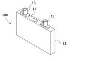
各電池セルは図24に示すように、外観を角形の外装缶12として、上端に正負の電極端子13を設けている。この電池セル10Xには、高出力のリチウムイオン二次電池が使用されることが多い。リチウムイオン二次電池の外装缶12は、中間電位を有しているため、電池セル表面が高電位となり、これを外装ケース55のグラウンドから絶縁する必要がある。このため、電池セルの外装缶を絶縁カバーや絶縁シートで多くなどの絶縁対策が施されている。
As shown in FIG. 24, each battery cell has a rectangular
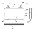
一般的には、電池セルの上部の電極端子を露出させるよう、図25に示すように袋状の熱収縮シート20Xで電池セルの上面を残して被覆する。具体的には、上下を筒状に開口した熱収縮シート20Xを適当な長さで裁断し、図26に示すように一方の開口端から電池セル10Xを挿入し、図27(a)、(b)に示すように熱収縮シート20Xを熱収縮させて外装缶の表面に密着させる。この際、電池セル10Xの底面で熱収縮シート20X同士を熱溶着して開口部分を閉塞し、さらに余白部分を裁断して、電池セル10Xの表面に熱収縮シートを被覆していた。
In general, as shown in FIG. 25, the battery cell is covered with a bag-shaped
しかしながら、余白部分を裁断して完全に除去することは困難であり、裁断によって電池セルの底面で熱収縮シートが破損して、外装缶の表面が部分的に表出する事態を回避するために、ある程度のマージンを取って裁断する必要がある。この結果、図25(b)や図27(b)に示すように、電池セル10Xの底面において、熱溶着線HLから熱溶着シート同士の接合面が突出することとなる。
However, it is difficult to completely remove the blank portion by cutting, in order to avoid a situation in which the heat shrink sheet is damaged at the bottom surface of the battery cell due to the cutting and the surface of the outer can is partially exposed. It is necessary to cut with some margin. As a result, as shown in FIG. 25 (b) and FIG. 27 (b), the joining surface between the heat welding sheets protrudes from the heat welding wire HL on the bottom surface of the
特に、熱収縮シートを熱収縮させるシュリンク工程においては、外装缶の底面の溶着部は収縮しないので、折りたたまれてひだ状となる。ひだ状部分は、相当の強度を有するため折り畳むことが困難であり、この結果、硬い突起が電池セルの底面から突出した状態となる。このような突起が大きいと、電池セルをセパレータに収納する際、セパレータの底面と干渉する虞がある。 In particular, in the shrinking process in which the heat-shrinkable sheet is thermally shrunk, the welded portion on the bottom surface of the outer can is not shrunk, so that it is folded into a pleated shape. Since the pleated portion has a considerable strength, it is difficult to fold, and as a result, the hard protrusion protrudes from the bottom surface of the battery cell. If such a protrusion is large, there is a possibility of interference with the bottom surface of the separator when the battery cell is stored in the separator.
一方で、電池セルを冷却プレート上に載置して、電池セルの底面を冷却プレートと熱結合させることで、冷却プレートを通じて電池セルを放熱させる冷却方式が提案されているものの、電池セルの底面に突起があると、電池セルと冷却プレートとの面接触が阻害されて、熱伝導が低下する問題もある。特に、ひだ状の形状は電池セル毎にまちまちで、突出量も一定しないため、接触状態が不安定となる。また上述したセパレータへの収納も阻害されることから、電池セル間に個体差が生じて、電池セルの歩留まりが悪くなるという問題があった。 On the other hand, although a cooling method has been proposed in which a battery cell is placed on a cooling plate and the bottom surface of the battery cell is thermally coupled to the cooling plate to dissipate the battery cell through the cooling plate, the bottom surface of the battery cell If there is a protrusion on the surface, the surface contact between the battery cell and the cooling plate is hindered, and there is a problem that heat conduction is lowered. In particular, the pleated shape varies for each battery cell, and the amount of protrusion is not constant, so that the contact state becomes unstable. In addition, since the storage in the separator described above is hindered, there is a problem that individual differences occur between the battery cells and the yield of the battery cells deteriorates.
本発明は、従来のこのような問題点を解決することを目的になされたものである。本発明の主な目的は、電池セルを熱収縮シートで被覆しつつ、接合面の突出を抑制し、放熱性の信頼性を高めた電池セル及び製造方法、電源装置並びにこれを備える車両を提供することにある。 The present invention has been made for the purpose of solving the conventional problems. A main object of the present invention is to provide a battery cell, a manufacturing method, a power supply device, and a vehicle including the same, in which the battery cell is covered with a heat-shrink sheet and the protrusion of the joint surface is suppressed and the reliability of heat dissipation is improved. There is to do.
上記の目的を達成するために、本発明の第1の側面に係る電池セルによれば、外装缶と、前記外装缶の外周面を被覆する防水性および絶縁性を有する熱収縮性の熱収縮シートと、を備える電池セルの製造方法であって、前記熱収縮シートを、前記外装缶の外周面を被覆可能な定型寸法にて用意する工程と、前記熱収縮シートで前記外装缶の外周面を覆うと共に、前記熱収縮シートを第一温度で加熱して前記外装缶の表面に密着させ、熱収縮シート同士を端縁で接合させて接合面を形成する、又は熱収縮シート同士を端縁で接合させて接合面を形成し、前記熱収縮シートで前記外装缶の外周面を覆うと共に、前記熱収縮シートを第一温度で加熱して前記外装缶の表面に密着させる工程と、前記接合面の突出部分を第二温度で加熱して、略平坦面を形成する工程と、を含むことができる。これにより、熱収縮シートで被覆した電池セルの表面から、接合面が突出する事態を抑制でき、複数の電池セルを積層する際に、接合面が突出することで同一平面に並べにくくなる自体を回避できる。 In order to achieve the above object, according to the battery cell of the first aspect of the present invention, an outer can and a heat-shrinkable thermal contraction having a waterproof and insulating property covering the outer peripheral surface of the outer can. A process for preparing the heat-shrinkable sheet in a fixed size capable of covering the outer peripheral surface of the outer can, and the outer peripheral surface of the outer can with the heat-shrinkable sheet The heat-shrinkable sheet is heated at a first temperature to adhere to the surface of the outer can, and the heat-shrinkable sheets are joined together at the edges to form a joining surface, or the heat-shrinkable sheets are edged Forming a bonding surface, covering the outer peripheral surface of the outer can with the heat-shrinkable sheet, and heating the heat-shrinkable sheet at a first temperature to adhere to the surface of the outer can; and the bonding Heat the projecting part of the surface at the second temperature to obtain a substantially flat surface Forming, it can contain. As a result, the situation where the joint surface protrudes from the surface of the battery cell covered with the heat shrink sheet can be suppressed, and when stacking a plurality of battery cells, the joint surface protrudes and it is difficult to arrange them on the same plane. Can be avoided.
また、第2の電池セルの製造方法によれば、前記第二温度を、前記第一温度よりも高温に設定することができる。これにより、熱収縮シートを熱収縮させる温度よりも高温で溶融して、接合面に平坦面を確実に形成できる。 Moreover, according to the manufacturing method of a 2nd battery cell, said 2nd temperature can be set to high temperature rather than said 1st temperature. Thereby, it melts at a temperature higher than the temperature at which the heat-shrinkable sheet is thermally shrunk, and a flat surface can be reliably formed on the joint surface.
さらに、第3の電池セルの製造方法によれば、前記略平坦面の形成において、前記接合部を挿入可能なスリットを開口した耐熱性のスペーサの一方の面を、前記外装缶の表面に当接させ、接合部を前記スリットから突出させ、この状態で加熱プレートに、前記スペーサの他方の面を押し当てて、前記接合面の突出部分を加熱プレートで溶融させて、略平坦面を形成、又は前記略平坦面の形成において、前記加熱プレートの上に前記スペーサを置き、前記スペーサに開口したスリットに前記接合面の突出部分を挿入して加熱プレートで溶融させて、略平坦面を形成できる。これにより、耐熱性のスペーサで、電池セルの表面を被覆する熱収縮シートの表面を保護しつつ、接合面の突出部分のみを選択的に加熱して平坦面を形成できる利点が得られる。また、接合面の突出量がスペーサの厚さで規定される一定量に均一に抑制できるので、電池セル毎の突出量の個体差やばらつきも抑制され、一定品質が保証されるという利点も得られる。 Further, according to the third battery cell manufacturing method, in forming the substantially flat surface, one surface of the heat-resistant spacer having a slit into which the joint can be inserted is applied to the surface of the outer can. Contacting, projecting the joint from the slit, pressing the other surface of the spacer against the heating plate in this state, melting the projecting portion of the joint surface with the heating plate, forming a substantially flat surface, Alternatively, in forming the substantially flat surface, the spacer can be placed on the heating plate, and a protruding portion of the joining surface can be inserted into a slit opened in the spacer and melted by the heating plate, thereby forming a substantially flat surface. . Thereby, while protecting the surface of the heat shrink sheet | seat which coat | covers the surface of a battery cell with a heat resistant spacer, the advantage which can selectively heat only the protrusion part of a joint surface and can form a flat surface is acquired. In addition, since the protruding amount of the joint surface can be uniformly suppressed to a certain amount defined by the thickness of the spacer, individual differences and variations in the protruding amount for each battery cell are also suppressed, and there is an advantage that a certain quality is guaranteed. It is done.
さらにまた、第4の電池セルの製造方法によれば、前記接合面が、前記電池セルの表面の長手方向に沿って、ほぼ中央の位置にて延長できる。これにより、電池セルを熱収縮シートで均等に被覆して信頼性を高めることができる。 Furthermore, according to the fourth method of manufacturing a battery cell, the joint surface can be extended at a substantially central position along the longitudinal direction of the surface of the battery cell. Thereby, a battery cell can be coat | covered uniformly with a heat-shrink sheet | seat, and reliability can be improved.
さらにまた、第5の電池セルの製造方法によれば、前記接合面が、前記電池セルの底面に形成できる。これにより、電池セルの底面から接合面が突出する事態を回避し、電池セルを自立させやすくなり、また電池セルの底面で冷却プレートと接合する際の熱結合状態を改善できる。 Furthermore, according to the fifth battery cell manufacturing method, the joint surface can be formed on the bottom surface of the battery cell. Thereby, the situation where a joint surface protrudes from the bottom face of a battery cell can be avoided, the battery cell can be easily made independent, and the thermal coupling state when joining the cooling plate on the bottom face of the battery cell can be improved.
さらにまた、第6の電池セルの製造方法によれば、前記スペーサに形成されたスリットが、前記接合面の幅方向の広がりよりも広い内径に形成できる。これにより、スリット内に確実に接合面を案内して、接合面の先端をすべて平坦面に形成できる。 Furthermore, according to the sixth method of manufacturing a battery cell, the slit formed in the spacer can be formed with an inner diameter wider than the width of the joint surface in the width direction. Thereby, a joining surface can be reliably guided in a slit, and all the front-end | tips of a joining surface can be formed in a flat surface.
さらにまた、第7の電池セルの製造方法によれば、前記スペーサの厚さが、前記接合面の突出部分の突出長さよりも薄く形成できる。これにより、接合面の突出部分を確実にスリットから表出させて、加熱プレートに接触させて平坦面を形成できる。 Furthermore, according to the seventh battery cell manufacturing method, the thickness of the spacer can be made thinner than the protruding length of the protruding portion of the joint surface. Thereby, the protrusion part of a joint surface can be reliably exposed from a slit, and a flat surface can be formed by making it contact with a heating plate.
さらにまた、第8の電池セルの製造方法によれば、前記外装缶を、外観を略矩形状とした角型に形成することができる。これにより、角型の外装缶の底面及び側面を熱収縮シートで被覆しつつ、底面の突出を抑制した安定的な形状とできる。 Furthermore, according to the eighth method for producing a battery cell, the outer can can be formed into a square shape whose appearance is substantially rectangular. Thereby, it can be set as the stable shape which suppressed the protrusion of the bottom face, coat | covering the bottom face and side face of a square-shaped exterior can with a heat-shrink sheet.
さらにまた、第9の電池セルの製造方法によれば、前記熱収縮シートで前記外装缶の外周面を覆う際の前記熱収縮シートを、前記外装缶の底面側において隅部を面取りすることができる。これにより、外装缶の底面側で接合面が、側方にはみ出す事態を回避し、スリット内に収まり易くできる。 Furthermore, according to the ninth method for producing a battery cell, the heat shrinkable sheet when the outer peripheral surface of the outer can is covered with the heat shrinkable sheet can be chamfered at the corner on the bottom side of the outer can. it can. As a result, it is possible to avoid the situation where the joining surface protrudes to the side on the bottom surface side of the outer can, and to easily fit in the slit.
さらにまた、第10の電池セルによれば、外装缶と、前記外装缶の外周面を被覆する防水性および絶縁性を有する熱収縮シートと、を備える電池セルであって、前記熱収縮シートは、前記外装缶の表面で、熱収縮シートの一部を接着させた接合部を有しており、前記接合部は、その先端を略平面状の平坦面に形成できる。これにより、熱収縮シートで被覆した電池セルの外装缶表面から、接合面が突出する事態を回避し、特に電池セルを複数積層する際に、表面を同一面に揃えやすくできる。 Furthermore, according to the tenth battery cell, a battery cell comprising an outer can and a heat-shrinkable sheet having waterproofness and insulation covering the outer peripheral surface of the outer can, wherein the heat-shrinkable sheet comprises: The surface of the outer can has a joint part to which a part of the heat-shrinkable sheet is adhered, and the joint part can be formed with a substantially flat flat surface at the tip. Thereby, the situation where a joint surface protrudes from the surface of the outer can of the battery cell covered with the heat shrink sheet can be avoided, and the surface can be easily aligned on the same surface particularly when a plurality of battery cells are stacked.
さらにまた、第11の電池セルによれば、前記平坦面は、前記接合部よりも断面視で幅広に形成できる。 Furthermore, according to the eleventh battery cell, the flat surface can be formed wider in cross-sectional view than the joint portion.
さらにまた、第12の電池セルによれば、さらに前記外装缶に設けた封口板と、前記封口板に設けた電極端子とを備え、前記熱収縮シートで、前記外装缶の、封口板を除く表面を被覆できる。これにより、外装缶の封口板を除く部位を熱収縮シートで絶縁すると共に、封口板に設けた電極端子は外部に表出させて、電池セルの出力を取り出し可能としている。 Furthermore, according to the twelfth battery cell, the battery pack further includes a sealing plate provided on the outer can and an electrode terminal provided on the sealing plate, and the heat shrink sheet removes the sealing plate of the outer can. The surface can be coated. Thus, the portion of the outer can other than the sealing plate is insulated by the heat shrink sheet, and the electrode terminals provided on the sealing plate are exposed to the outside so that the output of the battery cell can be taken out.
さらにまた、第13の電池装置によれば、上記電池セルを積層して構成できる。 Furthermore, according to the thirteenth battery device, the battery cells can be stacked.
さらにまた、第14の車両によれば、上記電源装置を搭載して構成できる。 Furthermore, according to the fourteenth vehicle, the power supply device can be mounted.
以下、本発明の実施の形態を図面に基づいて説明する。ただし、以下に示す実施の形態は、本発明の技術思想を具体化するための電池セル及び製造方法、電源装置並びにこれを備える車両を例示するものであって、本発明は電池セル及び製造方法、電源装置並びにこれを備える車両を以下のものに特定しない。また、本明細書は特許請求の範囲に示される部材を、実施の形態の部材に特定するものでは決してない。特に実施の形態に記載されている構成部品の寸法、材質、形状、その相対的配置等は特に特定的な記載がない限りは、本発明の範囲をそれのみに限定する趣旨ではなく、単なる説明例にすぎない。なお、各図面が示す部材の大きさや位置関係等は、説明を明確にするため誇張していることがある。さらに以下の説明において、同一の名称、符号については同一もしくは同質の部材を示しており、詳細説明を適宜省略する。さらに、本発明を構成する各要素は、複数の要素を同一の部材で構成して一の部材で複数の要素を兼用する態様としてもよいし、逆に一の部材の機能を複数の部材で分担して実現することもできる。
(実施例1)
Hereinafter, embodiments of the present invention will be described with reference to the drawings. However, the embodiment described below exemplifies a battery cell and a manufacturing method, a power supply device, and a vehicle including the same for embodying the technical idea of the present invention, and the present invention is a battery cell and a manufacturing method. The power supply device and the vehicle including the same are not specified as follows. Further, the present specification by no means specifies the members shown in the claims to the members of the embodiments. In particular, the dimensions, materials, shapes, relative arrangements, and the like of the component parts described in the embodiments are not intended to limit the scope of the present invention unless otherwise specified, and are merely explanations. It is just an example. Note that the size, positional relationship, and the like of the members shown in each drawing may be exaggerated for clarity of explanation. Further, in the following description, the same name and reference numeral indicate the same or the same members, and detailed description will be omitted as appropriate. Furthermore, each element constituting the present invention may be configured such that a plurality of elements are constituted by the same member and the plurality of elements are shared by one member, and conversely, the function of one member is constituted by a plurality of members. It can also be realized by sharing.
Example 1
本発明の実施例1に係る電池セルを図1〜図3に示す。これらの図に示す電池セル10は、リチウムイオン二次電池(Li−ion)である。ただ、電池セルはリチウムイオン二次電池には特定しない。本発明は、二次電池や一次電池を問わず、外装缶の表面を熱収縮シートで被覆する全ての電池の製造に採用できる。例えば電池セルを、ニッケル水素電池(NiCd)やニッケルカドミウム電池(Ni−MH)等の二次電池とし、あるいはマンガン電池やアルカリ電池等の一次電池としてもよい。さらに、電池セルは、角形電池に特定せず、横断面形状を円形や長円形、楕円形とする柱状の電池セルとすることもできる。
The battery cell which concerns on Example 1 of this invention is shown in FIGS. The
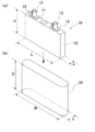
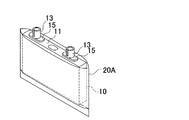
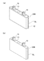
図1(a)に示す実施例1は外装缶を角形とする角型電池である。具体的には電池セル10の外装缶12は、その外形を、幅よりも厚さの薄い角形としている。さらに幅L、厚さdおよび高さHの有底箱形とし、上面は封口板11で閉塞している。封口板11には、絶縁部材15を介して電極端子13が装着されている。外装缶には、熱伝導性に優れたアルミニウム製としているが、これに限定されるもではなく、鉄やマグネシウムーアルミニウム合金等とすることもできる。
(熱収縮シート)
Example 1 shown in FIG. 1A is a prismatic battery having a rectangular outer can. Specifically, the outer can 12 of the
(Heat shrink sheet)
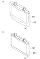
外装缶の表面は高電位となるため、これを絶縁する必要がある。このため、図1に示すように、外装缶12の、上面の封口板11の部分を除く外周面を、絶縁性の熱収縮シート20で被覆している。また、電源装置の内部に結露などで水が溜まった場合に、ショートや錆を防止するため、熱収縮シート20は防水性とする。また、熱収縮シート同士の接合面でピンホールなどが発生しないように溶着を行う。
Since the surface of the outer can has a high potential, it needs to be insulated. Therefore, as shown in FIG. 1, the outer peripheral surface of the
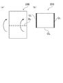
図1の例では、電池セル10は、熱収縮シート20を袋状として、外装缶12を挿入している。ここでは熱収縮シートとして、絶縁性および防水性を備えたPET(ポリエチレンテレフタレート)製を使用している。ただこれに限定されるものではなく、PVC(ポリ塩化ビニル)、PP(ポリプロピレン)、PE(ポリエチレン)およびPO(ポリオレフィン)等の絶縁性および防水性を備えた熱収縮シートとすることもできる。
In the example of FIG. 1, the
また熱収縮シート20は、電池セル10の外装缶12を挿入できる内径と深さを有し、外表面を被覆できる大きさに形成されている。この実施例1では、図1(b)に示す熱収縮シート20で形成した袋状の形状を、横幅Wを外装缶12の幅Lの1.05〜1.3倍とし、マチ幅tを外装缶12の厚さdの1.0〜1.2倍とし、さらに深さDを外装缶12の高さHの1.05〜1.2倍とする。また収縮温度に関しては、50〜120℃とする。ただし、熱収縮シートの仕様により一軸延伸特性または二軸延伸特性があり、さらに使用される材料により収縮率および熱収縮温度が異なる。
The heat-
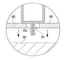
さらにまた、図4に示すような加熱プレート30の上に耐熱性を有するスペーサ40を置き、スペーサ40に開口されたスリット41に接合面GLを挿入することで、定量的な圧縮率を保った熔融圧縮部FLができる。これにより、熱収縮シート付き電池セルを定型寸法とすることが可能で、セパレータ等への安定した固定ができ、またスペーサ40を介すことで、加熱プレート30の加熱を外装缶12自体へ熱伝導するのを押さえることができ、さらに接合面GLを加熱プレート30で押さえる際の応力を分散することができため外装缶12及び電池セル10の破損を防ぐことができる。
Furthermore, by placing a heat-
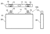
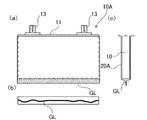
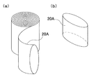
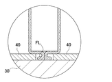
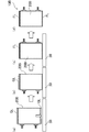
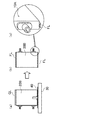
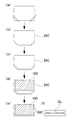
以下、電池セルの表面を熱収縮シートで被覆する手順を説明する。まず、外装缶12の外周面を被覆可能な熱収縮シート20Aを準備する。ここでは、図5(a)に示す筒状の熱収縮シート20Aを予め用意する。筒状の内径は、外装缶12が挿入できる大きさとする。この筒状熱収縮シート20Aを、図5(b)に示すように外装缶12の高さに従い定型寸法にて裁断する。そして、図6に示すように裁断された筒状の熱収縮シート20Aに外装缶12を挿入し、熱収縮シート20Aを第一温度で加熱して外装缶12の表面に密着させ、さらに外装缶12の底面側で、熱収縮シート20Aの端縁を熱溶着させて接合面GLを形成する。熱収縮シート20Aを熱収縮させる第一温度は、例えば50〜120℃とする。この状態では、外装缶12の周囲では熱収縮シート20Aが密着するものの、底面においては、図3に示すように熱溶着された接合面GLは収縮せずに、ひだ状に固まって突出する。この部分は硬化して、折り畳むことが困難である。特に端面側ほど、ひだ状が密集する傾向にある。このような突起は、形が定まらず電池セル毎に異なる上、外装缶12の底面にあるため、複数の電池セルを積層状態で、プレート上に載置する際に、高さが不揃いとなる原因となる。特に、冷媒の循環経路を内蔵した冷却プレート上に熱結合状態で載置して、冷却プレートで電池セルを冷却する方式においては、電池セルの底面と冷却プレートとの接触状態が一定せず、熱結合を阻害する原因となる。また、突出部分を折り畳むことは、突出部分が溶融されて強度を有することから困難であり、無理に折曲させると熱収縮シートが破れたり、外装缶の底面を破損する可能性もある。
(スペーサ)
Hereinafter, a procedure for coating the surface of the battery cell with the heat shrinkable sheet will be described. First, a
(Spacer)
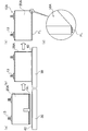
そこで、本実施の形態においては、接合面の突出部分を第二温度で加熱して、略平坦面を形成している。加熱には、加熱した加熱プレート30を使用する。ここでは、突出部分のみを選択的に加熱するよう、図7の分解斜視図に示すようにスペーサ40を利用している。スペーサ40は、電池セルの底面を被覆できるよう、電池セルの底面とほぼ同じ大きさか、これよりも大きく形成される。またスペーサ40は、その中央にスリット41を開口している。スリット41は、接合面GLが挿入できるよう、接合面GLよりも長く、かつ接合面GLのひだ状の揺らぎを収納できる幅に形成される。
Therefore, in the present embodiment, the protruding portion of the joint surface is heated at the second temperature to form a substantially flat surface. A
このスペーサ40を外装缶12の底面に当接させつつ、スリット41に接合面GLを挿入して、図8の断面図に示すようにスリット41を貫通させた接合面GLを、下方に突出させる。この状態で、電池セルの底面を、スリット41を介在させたまま加熱プレート30に押し当てて、突起の先端を溶融させる。この際に突起を加熱する第二温度は、硬化した熱収縮シートを溶融できる温度とする。好ましくは、第一温度よりも高い温度、例えば200℃〜250℃とする。この結果、図9に示すように突起の先端が溶融されて潰れ、平坦面が形成される。また、熱収縮シート同士が溶融された部分を、さらに加熱して潰すことで、熱収縮シート同士の接合をより強固にできる。特に、突起部分が加熱プレート30で押し潰されて横方向に拡げられる結果、接合面GLの幅が拡大されて安定度が増す。加えて、接合部分に仮にピンホールが形成されていたとしても、さらに高温で溶融させることでこれを排除することも期待できる。
While the
スペーサ40の厚さは、接合面GLの突出部分が小さくなるよう、好ましくは薄く形成される。特にスペーサ40の厚さによって、加熱後の突起の突出量が規定されるため、要求される突出量などに従って設定される。またスペーサの材質は、耐熱性を有する部材、例えば耐熱性ポリプロピレンなどが利用できる。
The
なお図7の例では、スリット41は長さ方向にわたって一定幅に形成しているが、部分的に幅を変更することもできる。特にひだ状は、電池セルの端縁ほど激しくなり、中間部分では比較的少ないことから、図10に示すように中央部分の幅を狭く、端縁の幅を広くした形状にスリットを開口させたスペーサ40Aを利用することもできる。あるいは、図11に示すように、スリットを一方の壁面で貫通させ、プレートを二股状に分岐させた形状にスペーサ40Bを形成してもよい。この形状のスペーサ40Bは、分岐させたプレート間をほぼ平行として、この離間された部分をスリットとして利用する。この形状のスペーサは、スペーサの面積を電池セルの底面よりも小さく形成することもできる。
In the example of FIG. 7, the
この方法であれば、接合面GLを加熱プレート30に押し付けることによって熱圧縮し、無駄な突出部分を容易に低減できる。特に、突出部分以外はスペーサで保護できるため、不用意に外装缶底面の熱収縮シートが破損される事態も回避でき、安全性や信頼性の面でも優れ、必要な部位のみを選択的に除去できる。また接合面の突出を簡単に一定量に規定することができ、電池セル間の個体差を容易に低減できる利点が得られる。ただ、熱した小手などを利用して、接合面GLの突出部分を個別に加熱して平坦部を形成することもできる。ただしこの方法では、手間がかかる上、突出量を一定量に規定するのが容易でない。
According to this method, the joining surface GL is pressed against the
外装缶12の底面で、突起を平坦面とした電池セル10Aは、プレート上に載置する際の安定性が増し、特に複数の電池セルを積層する際に、高さを同一面に揃えやすくできる。
The
なお、以上の例では裁断した筒状の熱収縮シートを電池セルに被覆した状態で、電池セル底面において筒状熱収縮シートの底面閉塞を行っているが、本発明はこの方法に限られるものでない。例えば裁断した筒状の熱収縮シートを、先に底面側を閉塞して、袋状とした上で、電池セルを袋状の熱収縮シートに収納するよう構成してもよい。この方法であれば、予め袋状にして電池セルの底面を確実に閉塞できるので、電池セル外装缶の側面と底面の被覆と同時に行う際に、例えば熱収縮シートの余白部分が電池セルの底面側で不足して底面の一部が露出するような事態を回避できる。
(実施例2)
In the above example, the bottom surface of the tubular heat-shrinkable sheet is closed on the bottom surface of the battery cell in a state where the cut tubular heat-shrinkable sheet is coated on the battery cell, but the present invention is limited to this method. Not. For example, the cut cylindrical heat-shrinkable sheet may be configured such that the bottom side is first closed to form a bag, and the battery cell is stored in the bag-shaped heat-shrinkable sheet. With this method, the bottom surface of the battery cell can be reliably closed by making it into a bag shape beforehand, so when performing simultaneously with the coating of the side surface and the bottom surface of the battery cell outer can, for example, the blank portion of the heat shrink sheet is the bottom surface of the battery cell. It is possible to avoid a situation where a part of the bottom surface is exposed due to shortage on the side.
(Example 2)
さらに実施例1では、図5(b)の斜視図及び図28(a)の正面図に示すように、熱収縮シート20Aを平面視で略矩形状となるように裁断している。この構成では、図28(b)の正面図に示すように熱収縮シート20Aに電池セル10を挿入して熱収縮させると、図28(c)の底面図に示すように、熱収縮シート20Aの接合面GLが、電池セル10の底面から側方にはみ出してしまうことがある。このような底面からのはみ出しがあると、スペーサに設けるスリットを大きくする必要が生じ、スペーサの大きさを電池セルの底面よりも大きく構成しなければならない。またスリットが大きくなると、電池セルをスペーサに載せる際に接合面GLのない部分までがスペーサ内に入り込む可能性も高くなって、ハンドリングが悪くなる。
Further, in Example 1, as shown in the perspective view of FIG. 5B and the front view of FIG. 28A, the heat-
そこで、好ましくは熱収縮シートの下部で隅部を面取りすることで、熱収縮シートの余分な部分、すなわち皺や撚れの原因になる部分を少なくして、このような皺や撚れを抑制できる。この例を、実施例2として図29(a)〜(f)に示す。ここでは、図29(a)に示すように、一旦矩形状に裁断した熱収縮シート20Cの、底面側の隅部をカットし、図29(b)に示すように六角形状とする。
Therefore, it is preferable to chamfer the corners at the bottom of the heat shrink sheet to reduce the extra parts of the heat shrink sheet, that is, the parts that cause wrinkles and twists, and suppress such wrinkles and twists. it can. This example is shown in FIGS. 29A to 29F as Example 2. FIG. Here, as shown in FIG. 29 (a), the corners on the bottom side of the heat-
さらに図29(c)に示すように、この熱収縮シート20Cの底面を熱溶着して閉塞し、袋状とした上で、図29(d)に示すように電池セル10Cを挿入する。なお、予め隅部をカットして袋状とした熱収縮シート20Cを用意しておくこともできる。この状態で、熱収縮シート20Cを第一温度で熱収縮させて、図29(e)に示すように外装缶の側面及び底面に密着させる。この構成であれば、図29(f)に示すように外装缶の底面において、皺になった接合面GLが、電池セル10Cの底面内に収まる。図29(d)に示すように、熱収縮前の接合面GLの余剰部分が、電池セルの端部近傍で少なくなっているためである。これによって、撚れが激しくなった接合面GLの隅部が、電池セル10Cの底面において側方に飛び出することを抑制でき、スリットを必要以上に大きく開口させる必要を無くし、スペーサのハンドリングを向上できる。
(実施例3)
Further, as shown in FIG. 29 (c), the bottom surface of the heat-
(Example 3)
以上の実施例1では、電池セルの底面に接合面が位置するように、熱収縮シート20Aで電池セルを被覆する例を説明した。ただ、この例に限られず、電池セルの側面に接合面を設ける構成においても、同様に加熱によって突出を排除できる。このような例を実施例3として、図12〜図16に示す。この電池セルは、図13に示すように熱収縮シート20Bを、U字状に折曲すると共に、両側で熱溶着して袋状に形成している。具体的には、図12(a)に示すように熱収縮シート20Bを長方形の寸法に切り出し、長方形の折曲線CLにて折りたたみ、折曲線CLと直交する両側面を接着剤または加熱溶着にて接合部GLを作成する。これによりこの図12(b)のような袋状とすることができ、図13(a)に示すように袋状中に電池セル10Bを挿入し、加温により熱収縮させ電池セル10Bに熱収縮シート20Bを密着させることで電池セル10Bを作成する。これにより、図13(b)に示されるように電池セル10Bの両側面に接合部GLができる。この接合部GLは、ホットメルト接着剤や熱硬化性接着剤さらに紫外線硬化性接着剤等を用いることができる。
In Example 1 described above, the example in which the battery cell is covered with the
さらに、作成される接合部GLは、熱収縮シートは樹脂製であるため加熱法や高周波印加法さらには超音波印加法等の加熱により加熱溶着することができる。この実施例では、加熱法を用い180〜210℃にて加熱溶着させている。ただし熱収縮シートの仕様により加熱溶着温度は異なる。 Furthermore, since the heat-shrinkable sheet is made of resin, the joint GL to be created can be heat-welded by heating such as a heating method, a high-frequency application method, or an ultrasonic application method. In this embodiment, heat welding is performed at 180 to 210 ° C. using a heating method. However, the heat welding temperature differs depending on the specifications of the heat shrinkable sheet.
しかし、接着剤または加熱溶着された接合部GLが、熱収縮シートを加温により熱収縮し電池セルに密着させた際に、蛇行変形を起こし固形化した切片となるため、図14に示すように接合部GLの合わせ面を平行に加熱プレート30で圧縮させることにより、接合部GLを溶解し再融合させることで略平面な熔融圧縮部FLができ、接合部GLの突出長を1/2〜1/3に圧縮することができる。この実施例では、加熱法を用い200〜270℃にて熔融圧縮させている。ただし熱収縮シートの仕様により熔融圧縮温度は異なる。
However, when the adhesive or heat-welded joint GL is heat-shrinked by heat-shrinking the heat-shrinkable sheet and brought into close contact with the battery cell, it forms a meandering deformed solid piece, as shown in FIG. By compressing the mating surface of the joint portion GL in parallel with the
さらに、熔融圧縮部FLは、図16に示すような加熱プレート30の上に耐熱性であるスペーサ40を置き、そこに開けられたスリット41に接合部GLを挿入することで定量的な圧縮率を保つことができる。これにより、熱収縮シート付き電池セル10Bを定型寸法とすることが可能で、セパレータ等への安定した固定ができ、またスペーサ40を介することで加熱プレート30の加熱を外装缶12自体への熱伝導を押さえることができ、さらに接合部GLは加熱プレート30で押さえる際の応力を分散することができため外装缶12及び電池セル10の破損を防ぐことができる。
Furthermore, the melt compression part FL places the
このように溶着封止された接合部をさらに最後に熔融圧縮することで、熱収縮シートの接合面が溶解し再融合するため、亀裂やピンホールの出現を効果的に低減でき、水等の前記外装缶への浸入リスクを防止できる。さらに熱収縮シートの接合部突出長を短縮させることができ、且つ略平面にすることにより、電源装置内の電池セル間をセパレータ内に設置する場合でも電池セルの設置固定が安定させることができ、一定外寸とすることができるためにセパレータとの密着性を高めることが可能である。
(電源装置)
By further melting and compressing the joint portion thus welded and sealed, the joint surface of the heat shrinkable sheet is melted and re-fused, so that the appearance of cracks and pinholes can be effectively reduced, such as water The risk of entering the outer can can be prevented. Furthermore, the joint protrusion length of the heat-shrinkable sheet can be shortened, and the installation and fixing of the battery cells can be stabilized even when the battery cells in the power supply device are installed in the separator by making it substantially flat. Since the outer diameter can be constant, it is possible to improve the adhesion with the separator.
(Power supply)
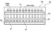
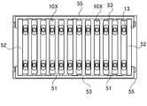
以上の電池セル10Aまたは10Bを複数、絶縁性のセパレータ51を介して積層して、図17〜図18に示すように連結した電源装置50を構成できる。電源装置50は、角形の電池セル10Aまたは10Bを複数、セパレータ51を介して積層した電池積層体の下部に絶縁シート54を配置して外装ケース55内に備えている。図17〜図18の例では、12個の角形電池セル10を積層している。また電池積層体の両側端面には、エンドプレート52を配置する。エンドプレート52同士は、電池積層体の側面に配置されたバインドバー53で固定される。これによりエンドプレート52同士の間で電池積層体を狭持するようにして固定する。バインドバー53は両端を折曲して折曲片とし、全体をコ字状としている。折曲片及びエンドプレート52にねじ穴を設けることで、バインドバー53をエンドプレート52に螺合して固定される。電池セル個数に関しては、電源装置の仕様電圧や電流により数量変更できることはいうまでもない。
(車両)
A plurality of the
(vehicle)
また、この電源装置は、車載用のバッテリシステムとして利用できる。電源装置を搭載する車両としては、エンジンとモータの両方で走行するハイブリッドカーやプラグインハイブリッドカー、あるいはモータのみで走行する電気自動車等の電動車両が利用でき、これらの車両の電源として使用される。 Moreover, this power supply device can be used as an in-vehicle battery system. As a vehicle equipped with a power supply device, an electric vehicle such as a hybrid car or a plug-in hybrid car that runs with both an engine and a motor, or an electric car that runs only with a motor can be used, and it is used as a power source for these vehicles. .
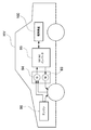
図19に、エンジンとモータの両方で走行するハイブリッドカーに電源装置を搭載する例を示す。この図に示す電源装置を搭載した車両HVは、車両HVを走行させるエンジン96及び走行用のモータ93と、モータ93に電力を供給する電源装置100と、電源装置100の電池を充電する発電機94とを備えている。電源装置100は、DC/ACインバータ95を介してモータ93と発電機94に接続している。車両HVは、電源装置100の電池を充放電しながらモータ93とエンジン96の両方で走行する。モータ93は、エンジン効率の悪い領域、例えば加速時や低速走行時に駆動されて車両を走行させる。モータ93は、電源装置100から電力が供給されて駆動する。発電機94は、エンジン96で駆動され、あるいは車両にブレーキをかけるときの回生制動で駆動されて、電源装置100の電池を充電する。
FIG. 19 shows an example in which a power supply device is mounted on a hybrid car that runs with both an engine and a motor. A vehicle HV equipped with the power supply device shown in this figure includes an
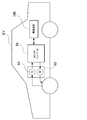
また図20に、モータのみで走行する電気自動車に電源装置を搭載する例を示す。この図に示す電源装置を搭載した車両EVは、車両EVを走行させる走行用のモータ93と、このモータ93に電力を供給する電源装置100と、この電源装置100の電池を充電する発電機94とを備えている。モータ93は、電源装置100から電力が供給されて駆動する。発電機94は、車両EVを回生制動する時のエネルギーで駆動されて、電源装置100の電池を充電する。
(蓄電用電源装置)
FIG. 20 shows an example in which a power supply device is mounted on an electric vehicle that runs only with a motor. A vehicle EV equipped with the power supply device shown in this figure includes a traveling
(Power storage device for power storage)
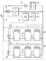
さらにこの電源装置は、車両などの移動体用の動力源としてのみならず、載置型の蓄電用設備としても利用できる。例えば家庭用、工場用の電源として、太陽光発電の電力や深夜電力等で充電し、必要時に放電する電源システム、あるいは日中の太陽光発電の電力を充電して夜間に放電する街路灯用の電源や、停電時に駆動する信号機用のバックアップ電源等にも利用できる。このような例を図21に示す。この図に示す電源装置100は、複数の電池パック81をユニット状に接続して電池ユニット82を構成している。各電池パック81は、複数の電池セルが直列及び/又は並列に接続されている。各電池パック81は、電源コントローラ84により制御される。この電源装置100は、電池ユニット82を充電用電源CPで充電した後、負荷LDを駆動する。このため電源装置100は、充電モードと放電モードを備える。負荷LDと充電用電源CPはそれぞれ、放電スイッチDS及び充電スイッチCSを介して電源装置100と接続されている。放電スイッチDS及び充電スイッチCSのON/OFFは、電源装置100の電源コントローラ84によって切り替えられる。充電モードにおいては、電源コントローラ84は充電スイッチCSをONに、放電スイッチDSをOFFに切り替えて、充電用電源CPから電源装置100への充電を許可する。また充電が完了し満充電になると、あるいは所定値以上の容量が充電された状態で負荷LDからの要求に応じて、電源コントローラ84は充電スイッチCSをOFFに、放電スイッチDSをONにして放電モードに切り替え、電源装置100から負荷LDへの放電を許可する。また、必要に応じて、充電スイッチCSをONに、放電スイッチDSをONにして、負荷LDの電力供給と、電源装置100への充電を同時に行うこともできる。
Furthermore, this power supply device can be used not only as a power source for a moving body such as a vehicle, but also as a stationary power storage facility. For example, as a power source for households and factories, a power supply system that is charged with solar power or midnight power and discharged when necessary, or a street light that is charged with solar power during the day and discharged at night It can also be used as a backup power source for traffic lights that are driven in the event of a power failure. Such an example is shown in FIG. The
電源装置100で駆動される負荷LDは、放電スイッチDSを介して電源装置100と接続されている。電源装置100の放電モードにおいては、電源コントローラ84が放電スイッチDSをONに切り替えて、負荷LDに接続し、電源装置100からの電力で負荷LDを駆動する。放電スイッチDSはFET等のスイッチング素子が利用できる。放電スイッチDSのON/OFFは、電源装置100の電源コントローラ84によって制御される。また電源コントローラ84は、外部機器と通信するための通信インターフェースを備えている。図21の例では、UARTやRS−232C等の既存の通信プロトコルに従い、ホスト機器HTと接続されている。また必要に応じて、電源システムに対してユーザが操作を行うためのユーザインターフェースを設けることもできる。
A load LD driven by the
各電池パック81は、信号端子と電源端子を備える。信号端子は、パック入出力端子DIと、パック異常出力端子DAと、パック接続端子DOとを含む。パック入出力端子DIは、他のパック電池や電源コントローラ84からの信号を入出力するための端子であり、パック接続端子DOは子パックである他のパック電池に対して信号を入出力するための端子である。またパック異常出力端子DAは、パック電池の異常を外部に出力するための端子である。さらに電源端子は、電池パック81同士を直列、並列に接続するための端子である。また電池ユニット82は並列接続スイッチ85を介して出力ラインOLに接続されて互いに並列に接続されている。
Each
本発明に係る電池セル及び製造方法、電源装置並びにこれを備える車両は、EV走行モードとHEV走行モードとを切り替え可能なプラグイン式ハイブリッド電気自動車やハイブリッド式電気自動車、電気自動車等の電源装置として好適に利用できる。またコンピュータサーバのラックに搭載可能なバックアップ電源装置、携帯電話等の無線基地局用のバックアップ電源装置、家庭内用、工場用の蓄電用電源、街路灯の電源等、太陽電池と組み合わせた蓄電装置、信号機等のバックアップ電源用等の用途にも適宜利用できる。 A battery cell, a manufacturing method, a power supply device, and a vehicle including the battery cell according to the present invention are used as a power supply device for a plug-in hybrid electric vehicle, a hybrid electric vehicle, an electric vehicle, or the like that can switch between an EV traveling mode and an HEV traveling mode. It can be suitably used. Also, a backup power supply device that can be mounted on a rack of a computer server, a backup power supply device for a wireless base station such as a mobile phone, a power storage device for home use and a factory, a power supply for a street light, etc. Also, it can be used as appropriate for applications such as a backup power source such as a traffic light.
10、10A、10B、10C、10X…電池セル
11…封口板
12…外装缶
13…電極端子
15…絶縁部材
20、20A、20B、20C、20X…熱収縮シート
30…加熱プレート
40、40A、40B…スペーサ
41…スリット
50、100…電源装置
51…セパレータ
52…エンドプレート
53…バインドバー
54…絶縁シート
55…外装ケース
81…電池パック
82…電池ユニット
84…電源コントローラ
85…並列接続スイッチ
93…モータ
94…発電機
95…DC/ACインバータ
96…エンジン
CL…折曲線
HL…熱溶着線
GL…接合面
FL…熔融圧縮部
HV、EV…車両
CP…充電用電源
LD…負荷
DS…放電スイッチ
CS…充電スイッチ
DI…パック入出力端子
DA…パック異常出力端子
DO…パック接続端子
HT…ホスト機器
OL…出力ライン
DESCRIPTION OF
Claims (14)
前記外装缶の外周面を被覆する防水性および絶縁性を有する熱収縮性の熱収縮シートと、
を備える電池セルの製造方法であって、
前記熱収縮シートを、前記外装缶の外周面を被覆可能な定型寸法にて用意する工程と、
前記熱収縮シートで前記外装缶の外周面を覆うと共に、前記熱収縮シートを第一温度で加熱して前記外装缶の表面に密着させ、熱収縮シート同士を端縁で接合させて接合面を形成する、又は熱収縮シート同士を端縁で接合させて接合面を形成し、前記熱収縮シートで前記外装缶の外周面を覆うと共に、前記熱収縮シートを第一温度で加熱して前記外装缶の表面に密着させる工程と、
前記接合面の突出部分を第二温度で加熱して、略平坦面を形成する工程と、
を含むことを特徴とする電池セルの製造方法。 An outer can,
A heat-shrinkable heat-shrink sheet having waterproof and insulating properties covering the outer peripheral surface of the outer can;
A method for producing a battery cell comprising:
Preparing the heat-shrinkable sheet in a fixed size capable of covering the outer peripheral surface of the outer can;
Covering the outer peripheral surface of the outer can with the heat shrinkable sheet, heating the heat shrinkable sheet at a first temperature to adhere to the surface of the outer can, and joining the heat shrinkable sheets to each other at the edge Forming or joining the heat-shrinkable sheets at the edges to form a bonding surface, covering the outer peripheral surface of the outer can with the heat-shrinkable sheet, and heating the heat-shrinkable sheet at a first temperature to form the outer package A process of adhering to the surface of the can;
Heating the protruding portion of the joining surface at a second temperature to form a substantially flat surface;
The manufacturing method of the battery cell characterized by including.
前記第二温度が、前記第一温度よりも高温に設定されてなることを特徴とする電池セルの製造方法。 It is a manufacturing method of the battery cell according to claim 1,
The method for producing a battery cell, wherein the second temperature is set higher than the first temperature.
前記略平坦面の形成において、前記接合部を挿入可能なスリットを開口した耐熱性のスペーサの一方の面を、前記外装缶の表面に当接させ、前記接合部を前記スリットを通じて前記スペーサの他方の面から突出させ、該他方の面を加熱された加熱プレートに押し当てて、前記接合面の突出部分を加熱プレートで溶融させて、略平坦面を形成してなる、又は前記略平坦面の形成において、前記加熱プレートの上に前記スペーサを置き、前記スペーサに開口したスリットに前記接合面の突出部分を挿入して加熱プレートで溶融させて、略平坦面を形成してなることを特徴とする電池セルの製造方法。 It is a manufacturing method of the battery cell according to claim 1 or 2,
In the formation of the substantially flat surface, one surface of a heat-resistant spacer having a slit into which the joint can be inserted is brought into contact with the surface of the outer can, and the joint is inserted into the other of the spacer through the slit. The other surface is pressed against a heated heating plate, and the protruding portion of the joining surface is melted with the heating plate to form a substantially flat surface, or the substantially flat surface In the formation, the spacer is placed on the heating plate, and a protruding portion of the joint surface is inserted into a slit opened in the spacer and melted by the heating plate, thereby forming a substantially flat surface. A method for manufacturing a battery cell.
前記接合面が、前記電池セルの表面の長手方向に沿って、ほぼ中央の位置にて延長されてなることを特徴とする電池セルの製造方法。 It is a manufacturing method of the battery cell according to any one of claims 1 to 3,
The method for manufacturing a battery cell, wherein the joining surface is extended at a substantially central position along the longitudinal direction of the surface of the battery cell.
前記接合面が、前記電池セルの底面に形成されてなることを特徴とする電池セルの製造方法。 It is a manufacturing method of the battery cell as described in any one of Claim 1 to 4, Comprising:
The method for manufacturing a battery cell, wherein the joining surface is formed on a bottom surface of the battery cell.
前記スペーサに形成されたスリットが、前記接合面の幅方向の広がりよりも広い内径に形成されてなることを特徴とする電池セルの製造方法。 It is a manufacturing method of the battery cell according to any one of claims 1 to 5,
The method of manufacturing a battery cell, wherein the slit formed in the spacer is formed to have an inner diameter wider than the width of the joint surface in the width direction.
前記スペーサの厚さが、前記接合面の突出部分の突出長さよりも薄く形成されてなることを特徴とする電池セルの製造方法。 It is a manufacturing method of the battery cell according to any one of claims 1 to 6,
The method of manufacturing a battery cell, wherein the spacer is formed thinner than the protruding length of the protruding portion of the joint surface.
前記外装缶が、外観を略矩形状とした角型に形成されてなることを特徴とする電池セルの製造方法。 It is a manufacturing method of the battery cell according to any one of claims 1 to 7,
The method of manufacturing a battery cell, wherein the outer can is formed in a square shape having an outer appearance of a substantially rectangular shape.
前記熱収縮シートで前記外装缶の外周面を覆う際の前記熱収縮シートが、前記外装缶の底面側において隅部を面取りされてなることを特徴とする電池セル A method for producing a battery cell according to any one of claims 3 to 8,
The battery cell, wherein the heat-shrinkable sheet when the outer peripheral surface of the outer can is covered with the heat-shrinkable sheet has its corners chamfered on the bottom surface side of the outer can.
前記外装缶の外周面を被覆する防水性および絶縁性を有する熱収縮シートと、
を備える電池セルであって、
前記熱収縮シートは、前記外装缶の表面で、熱収縮シートの一部を接着させた接合部を有しており、
前記接合部は、その先端を略平面状の平坦面に形成してなることを特徴とする電池セル。 An outer can,
A heat-shrink sheet having waterproofness and insulating properties covering the outer peripheral surface of the outer can;
A battery cell comprising:
The heat-shrinkable sheet has a joint part to which a part of the heat-shrinkable sheet is adhered on the surface of the outer can.
The junction part is formed by forming a tip of the joint part into a substantially flat flat surface.
前記平坦面は、前記接合部よりも断面視で幅広に形成されてなることを特徴とする電池セル。 The battery cell according to claim 10,
The battery cell, wherein the flat surface is formed wider than the joint portion in a cross-sectional view.
前記外装缶に設けた封口板と、
前記封口板に設けた電極端子と、
を備え、
前記熱収縮シートで、前記外装缶の、封口板を除く表面を被覆してなることを特徴とする電池セル。 The battery cell according to claim 10 or 11, further comprising:
A sealing plate provided on the outer can;
An electrode terminal provided on the sealing plate;
With
A battery cell, wherein the heat-shrink sheet covers a surface of the outer can excluding a sealing plate.
Priority Applications (1)
| Application Number | Priority Date | Filing Date | Title |
|---|---|---|---|
| JP2011043344A JP2012181971A (en) | 2011-02-28 | 2011-02-28 | Method of manufacturing battery cell, battery cell, power supply device, and vehicle having the power supply device |
Applications Claiming Priority (1)
| Application Number | Priority Date | Filing Date | Title |
|---|---|---|---|
| JP2011043344A JP2012181971A (en) | 2011-02-28 | 2011-02-28 | Method of manufacturing battery cell, battery cell, power supply device, and vehicle having the power supply device |
Publications (1)
| Publication Number | Publication Date |
|---|---|
| JP2012181971A true JP2012181971A (en) | 2012-09-20 |
Family
ID=47013017
Family Applications (1)
| Application Number | Title | Priority Date | Filing Date |
|---|---|---|---|
| JP2011043344A Pending JP2012181971A (en) | 2011-02-28 | 2011-02-28 | Method of manufacturing battery cell, battery cell, power supply device, and vehicle having the power supply device |
Country Status (1)
| Country | Link |
|---|---|
| JP (1) | JP2012181971A (en) |
Cited By (7)
| Publication number | Priority date | Publication date | Assignee | Title |
|---|---|---|---|---|
| JP2014096357A (en) * | 2012-10-12 | 2014-05-22 | Gs Yuasa Corp | Power storage element, cover sheet and covering method of container |
| JP2015056359A (en) * | 2013-09-13 | 2015-03-23 | 日立オートモティブシステムズ株式会社 | Prismatic secondary battery |
| KR101569452B1 (en) * | 2012-11-29 | 2015-11-16 | 주식회사 엘지화학 | Second Battery Having Film of Thermal Shrinkage Property |
| KR101891864B1 (en) | 2015-02-16 | 2018-08-24 | 주식회사 엘지화학 | Apparatus for Shaping Separator and Battery Cell Manufactured by Using the Same |
| JPWO2020262085A1 (en) * | 2019-06-28 | 2020-12-30 | ||
| JP2023548387A (en) * | 2020-11-02 | 2023-11-16 | パラトブ グループ エルエルシー | High voltage battery module with series connected cells and internal relays |
| JP7836582B2 (en) | 2020-11-02 | 2026-03-27 | パラトブ グループ エルエルシー | High-voltage battery module with series-connected cells and internal relays |
Citations (7)
| Publication number | Priority date | Publication date | Assignee | Title |
|---|---|---|---|---|
| JP2000200585A (en) * | 1999-01-04 | 2000-07-18 | Mitsubishi Electric Corp | Battery package |
| JP2002184364A (en) * | 2000-12-19 | 2002-06-28 | Matsushita Electric Ind Co Ltd | Prismatic battery and its packaging method |
| JP2003223872A (en) * | 2002-01-31 | 2003-08-08 | Taisei Plas Co Ltd | Resin coating method for lithium ion secondary battery and the battery |
| JP2007157427A (en) * | 2005-12-02 | 2007-06-21 | Mitsubishi Motors Corp | Lithium ion secondary battery |
| JP2011181485A (en) * | 2010-02-05 | 2011-09-15 | Sanyo Electric Co Ltd | Square battery, method of manufacturing the sane, and battery pack using the same |
| JP2012033419A (en) * | 2010-07-31 | 2012-02-16 | Sanyo Electric Co Ltd | Power supply device, vehicle using the same, battery cell, and method of manufacturing the battery cell |
| WO2012057169A1 (en) * | 2010-10-26 | 2012-05-03 | 三洋電機株式会社 | Power-supply device, vehicle using same, battery cell, and battery-cell manufacturing method |
-
2011
- 2011-02-28 JP JP2011043344A patent/JP2012181971A/en active Pending
Patent Citations (7)
| Publication number | Priority date | Publication date | Assignee | Title |
|---|---|---|---|---|
| JP2000200585A (en) * | 1999-01-04 | 2000-07-18 | Mitsubishi Electric Corp | Battery package |
| JP2002184364A (en) * | 2000-12-19 | 2002-06-28 | Matsushita Electric Ind Co Ltd | Prismatic battery and its packaging method |
| JP2003223872A (en) * | 2002-01-31 | 2003-08-08 | Taisei Plas Co Ltd | Resin coating method for lithium ion secondary battery and the battery |
| JP2007157427A (en) * | 2005-12-02 | 2007-06-21 | Mitsubishi Motors Corp | Lithium ion secondary battery |
| JP2011181485A (en) * | 2010-02-05 | 2011-09-15 | Sanyo Electric Co Ltd | Square battery, method of manufacturing the sane, and battery pack using the same |
| JP2012033419A (en) * | 2010-07-31 | 2012-02-16 | Sanyo Electric Co Ltd | Power supply device, vehicle using the same, battery cell, and method of manufacturing the battery cell |
| WO2012057169A1 (en) * | 2010-10-26 | 2012-05-03 | 三洋電機株式会社 | Power-supply device, vehicle using same, battery cell, and battery-cell manufacturing method |
Cited By (11)
| Publication number | Priority date | Publication date | Assignee | Title |
|---|---|---|---|---|
| JP2014096357A (en) * | 2012-10-12 | 2014-05-22 | Gs Yuasa Corp | Power storage element, cover sheet and covering method of container |
| KR101569452B1 (en) * | 2012-11-29 | 2015-11-16 | 주식회사 엘지화학 | Second Battery Having Film of Thermal Shrinkage Property |
| JP2015056359A (en) * | 2013-09-13 | 2015-03-23 | 日立オートモティブシステムズ株式会社 | Prismatic secondary battery |
| KR101891864B1 (en) | 2015-02-16 | 2018-08-24 | 주식회사 엘지화학 | Apparatus for Shaping Separator and Battery Cell Manufactured by Using the Same |
| JPWO2020262085A1 (en) * | 2019-06-28 | 2020-12-30 | ||
| WO2020262085A1 (en) * | 2019-06-28 | 2020-12-30 | 三洋電機株式会社 | Power source device, electric vehicle equipped with said power source device, and power storage device |
| CN113994528A (en) * | 2019-06-28 | 2022-01-28 | 三洋电机株式会社 | Power supply device, electric vehicle having the same, and power storage device |
| CN113994528B (en) * | 2019-06-28 | 2023-11-07 | 三洋电机株式会社 | Power supply device, electric vehicle having the same, and power storage device |
| JP7582767B2 (en) | 2019-06-28 | 2024-11-13 | 三洋電機株式会社 | Power supply device, electric vehicle equipped with the power supply device, and power storage device |
| JP2023548387A (en) * | 2020-11-02 | 2023-11-16 | パラトブ グループ エルエルシー | High voltage battery module with series connected cells and internal relays |
| JP7836582B2 (en) | 2020-11-02 | 2026-03-27 | パラトブ グループ エルエルシー | High-voltage battery module with series-connected cells and internal relays |
Similar Documents
| Publication | Publication Date | Title |
|---|---|---|
| KR102150679B1 (en) | Battery module, battery pack comprising the battery module and vehicle comprising the battery pack | |
| JP7039584B6 (en) | Power supply device, vehicle equipped with it, and power storage device | |
| CN107408646B (en) | Power supply device and vehicle equipped with the same | |
| KR100896131B1 (en) | Medium and large battery module | |
| JP5743791B2 (en) | Power supply device and vehicle equipped with power supply device | |
| JP6328842B2 (en) | Power supply device and vehicle equipped with the same | |
| EP2602840A2 (en) | Secondary battery pouch having improved stability, pouch-type secondary battery using same, and medium- or large-sized battery pack | |
| US9293785B2 (en) | Lithium ion secondary battery, vehicle, and battery mounting device | |
| JP2013012441A (en) | Electric power source device and vehicle including the same | |
| WO2012165493A1 (en) | Power source device for supplying power and vehicle provided with power source device | |
| JP7414808B2 (en) | Power supply device, electric vehicle and power storage device equipped with this power supply device, fastening member for power supply device, method for manufacturing fastening member for power supply device, method for manufacturing power supply device | |
| KR20170035218A (en) | Battery module, battery pack comprising the battery module and vehicle comprising the battery pack | |
| WO2012133708A1 (en) | Power source device and vehicle provided with power source device | |
| CN112534631B (en) | Power supply device and vehicle having the same | |
| KR102751965B1 (en) | Method of fabricating secondary battery with improved electrode tab disconnection and secondary battery using the same, and secondary battery module and pack comprising the same | |
| KR20130139472A (en) | Battery assembly having single electrode terminal connecting part | |
| KR20140056835A (en) | Battery module and battery pack comprising the same | |
| KR20130110943A (en) | Battery module of novel structure and battery pack comprising the same | |
| CN112272884B (en) | Battery pack and vehicle provided with same | |
| JP2013114954A (en) | Power supply unit and vehicle and power storage device incorporating the same | |
| WO2013002090A1 (en) | Power supply device, vehicle including same, and method for manufacturing power supply device | |
| KR20140033585A (en) | Secondary battery | |
| CN115053386B (en) | Power supply device, vehicle provided with same, and power storage device | |
| EP4050713A1 (en) | Power supply device, electric vehicle using same, and power storage device | |
| JP2012181971A (en) | Method of manufacturing battery cell, battery cell, power supply device, and vehicle having the power supply device |
Legal Events
| Date | Code | Title | Description |
|---|---|---|---|
| A521 | Request for written amendment filed |
Free format text: JAPANESE INTERMEDIATE CODE: A523 Effective date: 20121026 |
|
| A621 | Written request for application examination |
Free format text: JAPANESE INTERMEDIATE CODE: A621 Effective date: 20140128 |
|
| A977 | Report on retrieval |
Free format text: JAPANESE INTERMEDIATE CODE: A971007 Effective date: 20140617 |
|
| A131 | Notification of reasons for refusal |
Free format text: JAPANESE INTERMEDIATE CODE: A131 Effective date: 20140826 |
|
| A02 | Decision of refusal |
Free format text: JAPANESE INTERMEDIATE CODE: A02 Effective date: 20141224 |