JP2012181514A - Projection type display device - Google Patents
Projection type display device Download PDFInfo
- Publication number
- JP2012181514A JP2012181514A JP2012024057A JP2012024057A JP2012181514A JP 2012181514 A JP2012181514 A JP 2012181514A JP 2012024057 A JP2012024057 A JP 2012024057A JP 2012024057 A JP2012024057 A JP 2012024057A JP 2012181514 A JP2012181514 A JP 2012181514A
- Authority
- JP
- Japan
- Prior art keywords
- light
- projection
- light emitting
- display device
- emitting element
- Prior art date
- Legal status (The legal status is an assumption and is not a legal conclusion. Google has not performed a legal analysis and makes no representation as to the accuracy of the status listed.)
- Granted
Links
Images


Classifications
-
- G—PHYSICS
- G02—OPTICS
- G02B—OPTICAL ELEMENTS, SYSTEMS OR APPARATUS
- G02B27/00—Optical systems or apparatus not provided for by any of the groups G02B1/00 - G02B26/00, G02B30/00
- G02B27/10—Beam splitting or combining systems
- G02B27/1006—Beam splitting or combining systems for splitting or combining different wavelengths
- G02B27/102—Beam splitting or combining systems for splitting or combining different wavelengths for generating a colour image from monochromatic image signal sources
- G02B27/1026—Beam splitting or combining systems for splitting or combining different wavelengths for generating a colour image from monochromatic image signal sources for use with reflective spatial light modulators
-
- G—PHYSICS
- G03—PHOTOGRAPHY; CINEMATOGRAPHY; ANALOGOUS TECHNIQUES USING WAVES OTHER THAN OPTICAL WAVES; ELECTROGRAPHY; HOLOGRAPHY
- G03B—APPARATUS OR ARRANGEMENTS FOR TAKING PHOTOGRAPHS OR FOR PROJECTING OR VIEWING THEM; APPARATUS OR ARRANGEMENTS EMPLOYING ANALOGOUS TECHNIQUES USING WAVES OTHER THAN OPTICAL WAVES; ACCESSORIES THEREFOR
- G03B21/00—Projectors or projection-type viewers; Accessories therefor
- G03B21/14—Details
- G03B21/142—Adjusting of projection optics
-
- G—PHYSICS
- G03—PHOTOGRAPHY; CINEMATOGRAPHY; ANALOGOUS TECHNIQUES USING WAVES OTHER THAN OPTICAL WAVES; ELECTROGRAPHY; HOLOGRAPHY
- G03B—APPARATUS OR ARRANGEMENTS FOR TAKING PHOTOGRAPHS OR FOR PROJECTING OR VIEWING THEM; APPARATUS OR ARRANGEMENTS EMPLOYING ANALOGOUS TECHNIQUES USING WAVES OTHER THAN OPTICAL WAVES; ACCESSORIES THEREFOR
- G03B21/00—Projectors or projection-type viewers; Accessories therefor
- G03B21/14—Details
- G03B21/26—Projecting separately subsidiary matter simultaneously with main image
-
- G—PHYSICS
- G03—PHOTOGRAPHY; CINEMATOGRAPHY; ANALOGOUS TECHNIQUES USING WAVES OTHER THAN OPTICAL WAVES; ELECTROGRAPHY; HOLOGRAPHY
- G03B—APPARATUS OR ARRANGEMENTS FOR TAKING PHOTOGRAPHS OR FOR PROJECTING OR VIEWING THEM; APPARATUS OR ARRANGEMENTS EMPLOYING ANALOGOUS TECHNIQUES USING WAVES OTHER THAN OPTICAL WAVES; ACCESSORIES THEREFOR
- G03B35/00—Stereoscopic photography
- G03B35/16—Stereoscopic photography by sequential viewing
-
- H—ELECTRICITY
- H04—ELECTRIC COMMUNICATION TECHNIQUE
- H04N—PICTORIAL COMMUNICATION, e.g. TELEVISION
- H04N9/00—Details of colour television systems
- H04N9/12—Picture reproducers
- H04N9/31—Projection devices for colour picture display, e.g. using electronic spatial light modulators [ESLM]
- H04N9/3141—Constructional details thereof
- H04N9/315—Modulator illumination systems
- H04N9/3164—Modulator illumination systems using multiple light sources
Abstract
Description
本発明は、3次元画像が表示可能な投射型表示装置に関する。 The present invention relates to a projection display device capable of displaying a three-dimensional image.
投射型表示装置は、プロジェクタとも呼ばれ、液晶プロジェクタ、DLP(Digital Light Processing;登録商標、以下省略)プロジェクタ、LCOS(Liquid Crystal On Silicon)プロジェクタなどに分類される。 Projection type display devices are also called projectors, and are classified into liquid crystal projectors, DLP (Digital Light Processing; registered trademark, hereinafter omitted) projectors, LCOS (Liquid Crystal On Silicon) projectors, and the like.
そのうち、DLPプロジェクタは、DMD(Digital Micromirror Device;登録商標、以下省略)で代表される反射型ミラーアレイ素子を用いて映像を表示するものであり、2つのプリズムが対向配置された内部全反射プリズム(TIR[Total Internal Reflection]プリズム)が用いられる(例えば、特許文献1を参照)。 Among them, the DLP projector displays an image using a reflective mirror array element represented by DMD (Digital Micromirror Device; registered trademark, hereinafter omitted), and an internal total reflection prism in which two prisms are arranged to face each other. (TIR [Total Internal Reflection] prism) is used (see, for example, Patent Document 1).
一方で、画像表示装置において、アクティブシャッタ方式のメガネを使用して3次元の動画像や静止画像を視認させるためには、左眼用と右眼用の画像の信号をフレームシーケンシャル方式で切り替えるタイミングとメガネにおける左眼、右眼のアクティブシャッタの開閉のタイミングとを同期させる必要がある。画像表示装置が、表示パネルに画像を直接表示させる装置である場合には、この同期のために、赤外線通信、他の周波数帯での無線通信、有線での通信を用いることができる。 On the other hand, in the image display device, in order to visually recognize a three-dimensional moving image or still image using active shutter glasses, the timing for switching the signals of the left-eye and right-eye images by the frame sequential method. And the timing of opening / closing the active shutter of the left eye and the right eye of the glasses must be synchronized. When the image display device is a device that directly displays an image on the display panel, infrared communication, wireless communication in another frequency band, or wired communication can be used for this synchronization.
なお、液晶プロジェクタにおいては、検出投射光を投射してスクリーンから反射した光を検出することで、投射レンズの焦点を自動的に調整する技術が知られている(例えば、特許文献2を参照)。特許文献2に記載の技術では、3原色で光変調するためのLCD(Liquid Crystal Display)でなる透過型パネルと、色毎のLCDより出射した光を合成するプリズム(又はミラー)と、合成した光をスクリーンへ拡大投射する投射レンズとからなる光学系において、プリズム(又はミラー)と投射レンズの間に半透明反射膜手段を配置して、LCDとは別に設けられた発光部からの検出投射光の出力を上記投射レンズを介してスクリーン側へ投射し、同じく半透明反射膜手段及び上記投射レンズを介してスクリーンからの反射光を検出し、焦点の調整に用いている。 In a liquid crystal projector, a technique for automatically adjusting the focus of a projection lens by projecting detection projection light and detecting light reflected from a screen is known (see, for example, Patent Document 2). . In the technique described in Patent Document 2, a transmissive panel composed of an LCD (Liquid Crystal Display) for light modulation with three primary colors and a prism (or mirror) that synthesizes light emitted from the LCD for each color are combined. In an optical system composed of a projection lens that projects light onto a screen in an enlarged manner, a semitransparent reflective film means is disposed between the prism (or mirror) and the projection lens, and detection projection from a light emitting unit provided separately from the LCD The light output is projected to the screen side through the projection lens, and the reflected light from the screen is also detected through the semitransparent reflection film means and the projection lens, and used to adjust the focus.
上述のように、表示パネルに直接画像を表示して視認させる画像表示装置である場合には、アクティブシャッタの開閉を無線、有線を問わない通信手段により制御できる。
しかしながら、画像表示装置が投射型である場合には、赤外線発光素子を有する赤外線送信部を装置本体に備えるようにし、映像を投射するスクリーンに赤外線送信部から赤外線を投射し、そこで反射した赤外線を用いて同期をとることが好ましい。このように反射を用いる理由としては、投射型表示装置では、視聴者がスクリーンの映像を鑑賞するのが前提であるため、スクリーン内から赤外線を発すると共にメガネの受光部を映像側に向けておくと最も効率的で利便性も高いこと、並びに、別付けの送信器をスクリーン近傍に設置するよりも低コストで済むことなどが挙げられる。
As described above, in the case of an image display device that directly displays an image on a display panel for visual recognition, the opening and closing of the active shutter can be controlled by communication means regardless of wireless or wired.
However, when the image display apparatus is a projection type, the apparatus main body is provided with an infrared transmission unit having an infrared light emitting element, and infrared rays are projected from the infrared transmission unit onto a screen on which an image is projected, and the reflected infrared rays are reflected there. It is preferable to use it for synchronization. The reason for using reflection in this way is that the projection display device is premised on the viewer viewing the screen image, so that infrared rays are emitted from the screen and the light-receiving part of the glasses is directed to the image side. And the most efficient and convenient, and the cost is lower than installing a separate transmitter near the screen.
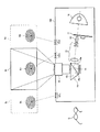
図10は、従来技術による投射型表示装置において、アクティブシャッタ方式のメガネを用いて画像を立体視させるために赤外線送信部を設けるように改良した構成を示す概略図である。図10に示す3次元画像表示が可能な投射型表示装置(3Dプロジェクタ)100は、光源装置10と、光源装置10から発せられた光を赤、緑、青の3色に時分割するカラーホイール11と、カラーホイール11を介した光を入射して内部で全反射させ照度分布が均一な状態で出射するロッドインテグレータ12、ロッドインテグレータ12から出射した光を集光する複数のレンズを有するコンデンサレンズ13、DMD14、2つの三角プリズム15a,15bが対向配置されたTIRプリズム15、並びに、TIRプリズム15からの出射光をスクリーンSに投影する投射レンズ16を備える。ここで、TIRプリズム15は、その内部反射面(境界面)15cにてコンデンサレンズ13からの出射光を反射してDMD14に入射させる。そして、TIRプリズム15は、その入射光がDMD14で反射した光が上記内部反射面15cを透過し、投射レンズ16に出射するようになっている。
FIG. 10 is a schematic diagram illustrating a configuration in which an infrared transmission unit is provided in order to stereoscopically view an image using active shutter glasses in a projection display device according to the related art. A projection display device (3D projector) 100 capable of displaying a three-dimensional image shown in FIG. 10 includes a
投射レンズ16から投影された映像は、アクティブシャッタを有する3D対応メガネGで視聴可能となるが、上述したように、映像に、右眼・左眼のアクティブシャッタの開閉を同期させる必要がある。そのため、3Dプロジェクタ100の本体には、赤外線発光素子を投射光学系とは別に設けている。
The video projected from the
図10では、3Dプロジェクタ100にレンズシフト機能をもたせており、そのため、図示するように、投射光学系とは別に3箇所の赤外線発光素子101C,101L,101Rを配置することになる。赤外線発光素子101Cは、レンズシフトしていないときの画像位置に対応して配設された通常用の素子であり、これによりスクリーン上には画像Sの一部分に赤外画像SiCが投射される。赤外線発光素子101Lは、左側にレンズシフトしたときの画像位置に対応して配設された素子であり、これにより画像SL(なお、画像SLの右端は図示していない)の一部分に赤外画像SiLが投射される。赤外線発光素子101Rは、右側にレンズシフトしたときの画像位置に対応して配設された素子であり、これにより画像SR(なお、画像SRの左端は図示していない)の部分に赤外画像SiRが投射される。メガネGは、シフトの位置に応じていずれか1から発光された1つの赤外画像を受光部で受光し、その赤外線の強度(の変化)に基づき、つまり赤外線のパルスに基づき、左右のアクティブシャッタの開閉を制御する。
In FIG. 10, the
このように、3D画像とアクティブシャッタ方式のメガネを同期させて視聴者に画像を立体視させるためには、赤外線送信部を投射型表示装置の本体に搭載しなければならないが、そのために次のような課題が生じる。無論、赤外線の代わりに紫外線や可視光線を用いても、基本的に同様の課題が生じる。
(1)赤外線送信部は装置本体の側面などに取り付けることになり、内部レイアウトやデザインに制限がある。
(2)スクリーンからの反射を利用するため、赤外線の指向性をスクリーン側に合わせるなど微妙な設定が必要となる。
As described above, in order to synchronize the 3D image and the active shutter glasses to allow the viewer to stereoscopically view the image, the infrared transmission unit must be mounted on the main body of the projection display device. Such a problem arises. Of course, even if ultraviolet rays or visible rays are used instead of infrared rays, basically the same problem occurs.
(1) The infrared transmitter is attached to the side surface of the apparatus main body, and there are restrictions on the internal layout and design.
(2) Since reflection from the screen is used, delicate settings such as matching the directivity of infrared rays to the screen side are required.
(3)赤外線送信部自体の角度特性がブロードであり、スクリーンと装置本体が離れれば離れるほど感度が悪くなるため、感度不足を補う必要がある。そのため、赤外線発光素子の出力を大きくするか、若しくは赤外線発光素子に画像用とは異なるレンズを設けるか、若しくは赤外線発光素子101L,101C,101Rとしてそれぞれ3個ずつ設けたように赤外線発光素子の数を増やすことが必要になる。 (3) The angular characteristics of the infrared transmitter itself are broad, and the sensitivity becomes worse the further away from the screen and the apparatus body, so it is necessary to compensate for the lack of sensitivity. Therefore, increase the output of the infrared light emitting element, or provide the infrared light emitting element with a lens different from that for images, or infrared light emitting as if three infrared light emitting elements 101 L , 101 C , 101 R were provided. It is necessary to increase the number of elements.
(4)画像を投射する投射レンズとしてズームレンズを使用する場合は、ワイド側、テレ側で距離が異なるため、赤外線発光素子の設置条件が複雑になる。
(5)投射型表示装置にレンズシフト機能をもたせる場合は、投影画像とスクリーンの位置関係が調節可能なため、より広い方向に赤外線を向ける必要があるが、一方で高感度を保つために指向性をある程度保つ必要がある。そのためには、図10において3箇所の赤外線発光素子101L,101C,101Rで示したように、レンズシフトに対応する画像位置に投射できるような配置で、別途赤外線発光素子を設ける必要がある。
(4) When a zoom lens is used as a projection lens for projecting an image, the distance is different between the wide side and the tele side, so that the installation conditions of the infrared light emitting elements are complicated.
(5) When the projection display device is provided with a lens shift function, the positional relationship between the projected image and the screen can be adjusted. Therefore, it is necessary to direct infrared rays in a wider direction. It is necessary to keep the sex to some extent. For this purpose, as shown by three infrared light emitting elements 101 L , 101 C , and 101 R in FIG. 10, it is necessary to separately provide infrared light emitting elements so that they can be projected onto image positions corresponding to lens shifts. is there.
また、喩え特許文献1に記載の技術を適用し、上記検出投射光を赤外線を含むようにして、上記(1)〜(5)のような課題を解決しようとすると、新たに次のような課題が生じる。無論、赤外線の代わりに紫外線や可視光線を用いても、基本的に同様の課題が生じる。
(6)赤外光出力が必要の無い一般的な光学系と比べて、プリズムやミラーなど半透明反射膜手段やそれを保持するための補助的な部品も含め、追加部品が必要となり、コストや装置サイズが上がってしまう。
(7)同じく上記追加部品を挿入する空間を確保するためにLCDのパネルから投射レンズまでの距離、すなわちバックフォーカスが長くなる。これにより、投射レンズ設計においてより強い正のパワーと負のパワーを必要とすることになるため、レンズ枚数が増加し、コストや装置サイズが上がってしまう。
Further, when applying the technique described in Patent Document 1 so that the detected projection light includes infrared rays and attempts to solve the problems (1) to (5), the following problems are newly generated. Arise. Of course, even if ultraviolet rays or visible rays are used instead of infrared rays, basically the same problem occurs.
(6) Compared to a general optical system that does not require infrared light output, additional parts are required, including semi-transparent reflective film means such as prisms and mirrors, and auxiliary parts for holding the same. And device size will increase.
(7) Similarly, the distance from the LCD panel to the projection lens, that is, the back focus is increased in order to secure a space for inserting the additional component. This requires stronger positive power and negative power in the projection lens design, which increases the number of lenses and increases the cost and device size.
(8)同じく上記追加部品により反射或いは透過損失が増え投射画像の光出力が低下する。さらに、追加部品がミラーの場合は安価であるが斜めに挿入された平行平板による非点収差が発生し結像性能を劣化させる。
(9)共通プラットフォームを使って3D対応と3D非対応の投射型表示装置を製造する場合、3D非対応の装置にも上記追加部品やレンズ枚数の多い投射レンズが必要となり余分なコストを背負うことになる。
(8) Similarly, reflection or transmission loss increases due to the additional components, and the light output of the projected image decreases. Further, when the additional part is a mirror, it is inexpensive, but astigmatism is caused by the parallel plate inserted obliquely, and the imaging performance is deteriorated.
(9) When manufacturing a 3D-compatible and 3D-compatible projection display device using a common platform, the 3D-incompatible device also requires a projection lens with a large number of the above-mentioned additional components and the number of lenses, and bears extra costs. become.
本発明は、上述のような実状に鑑みてなされたものであり、その目的は、3次元画像が表示可能な投射型表示装置において、赤外線発光素子等の発光素子を投射型表示装置の本体に搭載するに際し、発光素子の数や出力を増やすことなく、余計な追加部品を設けずにレンズシフトやズームに対応することを可能にすることにある。 The present invention has been made in view of the above situation, and an object of the present invention is to provide a light emitting element such as an infrared light emitting element in the main body of the projection display apparatus in a projection display apparatus capable of displaying a three-dimensional image. In mounting, it is possible to cope with lens shift and zoom without increasing the number of light-emitting elements and the output, and without providing additional components.
上記課題を解決するために、本発明の第1の技術手段は、2つのプリズムが対向配置された内部全反射プリズムと、投射レンズとを備え、光源から発せられた光を前記内部全反射プリズムを介して前記投射レンズから投射する、3次元画像が表示可能な投射型表示装置であって、発光素子をさらに備え、該発光素子は、前記内部全反射プリズムに光線を入射し、該光線を前記内部全反射プリズムの内部反射面で反射させ前記投射レンズを介して投射させるように、配置することを特徴としたものである。 In order to solve the above-described problem, a first technical means of the present invention includes an internal total reflection prism in which two prisms are arranged to face each other and a projection lens, and transmits light emitted from a light source to the internal total reflection prism. A projection-type display device that can display a three-dimensional image projected from the projection lens via the projection lens, further comprising a light-emitting element, and the light-emitting element makes a light beam incident on the internal total reflection prism. It is arranged so as to be reflected by the internal reflection surface of the internal total reflection prism and projected through the projection lens.
本発明の第2の技術手段は、第1の技術手段において、前記発光素子は、前記内部全反射プリズムに対して、前記光源から発せられた光の入射面、及び前記投射レンズへの出射面、とは異なる面から、前記光線を入射するように配置することを特徴としたものである。 According to a second technical means of the present invention, in the first technical means, the light emitting element has an incident surface of light emitted from the light source and an output surface to the projection lens with respect to the internal total reflection prism. The light beam is arranged so as to be incident from a different surface.
本発明の第3の技術手段は、第1の技術手段において、前記投射型表示装置は、反射型ミラーアレイ素子をさらに備え、光源から発せられた光を前記反射型ミラーアレイ素子及び前記内部全反射プリズムを介して前記投射レンズから投射することを特徴としたものである。 According to a third technical means of the present invention, in the first technical means, the projection display device further includes a reflective mirror array element, and emits light emitted from a light source to the reflective mirror array element and the entire internal mirror. Projection is performed from the projection lens via a reflecting prism.
本発明の第4の技術手段は、第3の技術手段において、前記発光素子は、前記内部全反射プリズムに対して、前記光源から発せられた光の入射面、前記反射型ミラーアレイ素子で反射された光の入射面、及び前記投射レンズへの出射面、とは異なる面から、前記光線を入射するように配置することを特徴としたものである。 According to a fourth technical means of the present invention, in the third technical means, the light emitting element reflects the incident surface of light emitted from the light source with respect to the internal total reflection prism, the reflection type mirror array element. The light beam is disposed so as to be incident from a surface different from the incident surface of the incident light and the exit surface to the projection lens.
本発明の第5の技術手段は、第1〜第4のいずれか1の技術手段において、前記発光素子は、発光ダイオードであることを特徴としたものである。 According to a fifth technical means of the present invention, in any one of the first to fourth technical means, the light-emitting element is a light-emitting diode.
本発明の第6の技術手段は、第1〜第4のいずれか1の技術手段において、前記発光素子は、レーザー素子であるとしたものである。 According to a sixth technical means of the present invention, in any one of the first to fourth technical means, the light emitting element is a laser element.
本発明の第7の技術手段は、第1〜第6のいずれか1の技術手段において、前記発光素子は、前記投射レンズのF値が示す有効取り込み角度に相当する半値角をもつことを特徴としたものである。 According to a seventh technical means of the present invention, in any one of the first to sixth technical means, the light emitting element has a half-value angle corresponding to an effective capture angle indicated by an F value of the projection lens. It is what.
本発明の第8の技術手段は、第1〜第7のいずれか1の技術手段において、前記投射レンズから投射され、被投射面で反射した前記光線は、アクティブシャッタ方式の3次元画像視聴用メガネにおけるアクティブシャッタの開閉に用いられることを特徴としたものである。 According to an eighth technical means of the present invention, in any one of the first to seventh technical means, the light beam projected from the projection lens and reflected by the projection surface is used for viewing an active shutter type three-dimensional image. It is used for opening and closing an active shutter in glasses.
本発明の第9の技術手段は、第1〜第8のいずれか1の技術手段において、前記発光素子は、赤外線発光素子又は紫外線発光素子であり、前記内部全反射プリズムは、前記内部反射面に可視光用の反射防止膜を設けたことを特徴としたものである。 According to a ninth technical means of the present invention, in any one of the first to eighth technical means, the light emitting element is an infrared light emitting element or an ultraviolet light emitting element, and the internal total reflection prism is the internal reflection surface. This is characterized in that an antireflection film for visible light is provided.
本発明によれば、3次元画像が表示可能な投射型表示装置において、赤外線発光素子等の発光素子を投射型表示装置の本体に搭載するに際し、発光素子の数や出力を増やすことなく、余計な追加部品を設けずにレンズシフトやズームに対応することができる。 According to the present invention, in a projection display device capable of displaying a three-dimensional image, when a light emitting element such as an infrared light emitting element is mounted on the main body of the projection display device, the number of light emitting elements and output are not increased. It is possible to cope with lens shift and zoom without providing additional components.
本発明に係る投射型表示装置は、その本体に発光素子を備えることを特徴とする。以下、基本的にこのような発光素子として、不可視光線である赤外線を発光する赤外線発光素子を使用した例を挙げて、本発明について説明する。但し、このような発光素子は、赤外線に限らず、不可視光線の他の例である紫外線を発光する素子であっても、若しくは可視光線を発光する素子であっても、実際に投射型表示装置から映像として投映される投射光のスペクトルと異なる帯域の光線を発光する素子であれば、同様に適用できる。 The projection type display device according to the present invention is characterized in that the main body includes a light emitting element. Hereinafter, the present invention will be described with reference to an example in which an infrared light emitting element that emits infrared light that is invisible light is basically used as such a light emitting element. However, such a light-emitting element is not limited to infrared light, and may be an element that emits ultraviolet light, which is another example of invisible light, or an element that emits visible light. Any element that emits light in a band different from the spectrum of the projected light projected as an image from the above can be similarly applied.
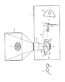
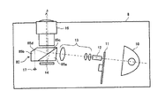
図1は、本発明に係る投射型表示装置の一構成例を示す概略図で、図中、1は本発明に係る3次元画像表示対応の投射型表示装置(以下、単に「3Dプロジェクタ」と呼ぶ)、Sはスクリーン上に投影された画像、Gは3D対応メガネである。 FIG. 1 is a schematic view showing a configuration example of a projection display device according to the present invention. In FIG. 1, reference numeral 1 denotes a projection display device (hereinafter simply referred to as “3D projector”) according to the present invention. S) is an image projected on the screen, and G is 3D-compatible glasses.
3Dプロジェクタ1は、光源装置10、カラーホイール11、ロッドインテグレータ12、コンデンサレンズ13、DMDで代表される反射型ミラーアレイ素子(以下、DMD)14、TIRプリズム15、及び投射レンズ16を備え、光源装置10から発せられた光をDMD14及びTIRプリズム15を介して投射レンズ16から投射する装置である。また、3Dプロジェクタ1は、通常の2次元画像の他に、3D画像が投射により表示可能となっている。
The 3D projector 1 includes a
光源装置10は、例えばメタルハライドランプや超高圧水銀ランプなどの高輝度のランプを有するよう構成すればよい。カラーホイール11は、赤、緑、青の3原色のフィルタを含み、それらが高速に回転するように構成され、これにより光源装置10から発せられた光を赤、緑、青の3色に時分割する。なお、カラーホイール11は、輝度を上げるために無色透明の部分又は黄色のフィルタなどを含むように構成してもよい。
The
ロッドインテグレータ12及びコンデンサレンズ13は、光源装置10とDMD14との間に配置される。ロッドインテグレータ12は、カラーホイール11を介した光を入射して内部で全反射させ照度分布が均一な状態で出射する。コンデンサレンズ13は、ロッドインテグレータ12から出射した光を集光し、TIRプリズム15に出射するレンズ群である。
The
DMD14は、画素数に相当する数の微小鏡面(マイクロミラー)を平面に配列した表示素子であり、後述のTIRプリズム15の内部反射面(境界面)15cで反射した光を入射し、図示しない制御部により画素信号に合わせて個々のミラーを駆動することで、反射光により画像を形成し、TIRプリズム15に戻す。ここで、DMD14は、カラーホイール11の高速な回転に同期した赤、緑、青の順次信号で各色の画像を反射することで、カラー画像をTIRプリズム15に戻すことが可能になっている。
The
TIRプリズム15は、2つの三角プリズム15a,15bが対向配置されており、その内部反射面(境界面)15cにて所定の入射角より小さい角度で入射した光のみを通過させ、それ以外を全反射するようになっている。内部反射面15cは、2つの三角プリズム15a,15bの斜辺面を合わせた部分に設けられている。内部反射面15cは、例えば空気層等により屈折率の低い層を形成してもよい。より具体的には、対向面において金属又は誘電体が真空蒸着されて形成されたスペーサを設けて微小間隔の空気層を形成してもよいし、一方の三角プリズムの対向面において周縁の全周に凸部を設けることで、周縁以外の部分を凹部として空気層を形成するなどしてもよい。このようにして形成された屈折率の低い層と三角プリズム15a,15bとの屈折率の比により、臨界角を決めることができる。
The
そして、TIRプリズム15は、コンデンサレンズ13からの出射光を内部反射面15cにて反射してDMD14に入射させ、DMD14でその入射光が反射した光を入射して内部反射面15cを透過させ、投射レンズ16に出射するように配置されている。投射レンズ16は、TIRプリズム15からの出射光を入射し、スクリーンに投影するレンズである。投射レンズ16からスクリーンに投影される画像は、DMD14により高速で順次反射された赤、緑、青の画像となり、結果としてカラー画像になる。
The
本発明の主たる特徴として、3Dプロジェクタ1には赤外線発光素子17が設けられている。特に本発明では、この赤外線発光素子17を図1のように投射光学系の一部として配置する。より具体的には、赤外線発光素子17は、TIRプリズム15に赤外線を入射し、その赤外線をTIRプリズム15の内部反射面15cで反射させ投射レンズ16を介して投射させるように、配置する。赤外線と光源からの光とがここで説明したような光路(好ましくは図1のような光路)を辿ることができるように、コンデンサレンズ13や投射レンズ16に対するTIRプリズム15の配置だけでなく、内部反射面15cにおける臨界角なども決めておけばよい。
As a main feature of the present invention, the 3D projector 1 is provided with an infrared
これにより、スクリーン上の画像Sの一部分に赤外画像Siも投射される。ここで赤外画像は、例えば図示したように画面中心部のみ丸となるような映像とするか、矩形となるような映像とすればよく、無論、他の形状の映像を採用してもよく、その大きさも問わない。 Thereby, the infrared image S i is also projected onto a part of the image S on the screen. Here, the infrared image may be, for example, an image in which only the center portion of the screen is a circle as shown in the figure, or an image having a rectangular shape. Of course, an image of another shape may be adopted. It doesn't matter how big it is.
そして、投射レンズ16から投影された画像(動画像や静止画像)は、それが3D画像である場合、アクティブシャッタ方式の3D対応メガネGで視聴者に視聴させることになる。その際、3D画像として視認させるためには、画像に、右眼・左眼のアクティブシャッタの開閉を同期させる必要がある。そのため、赤外線発光素子17から発光しスクリーン上で反射した赤外線の信号を、3D対応メガネGにおけるアクティブシャッタの開閉に用いる。
When the image (moving image or still image) projected from the
より具体的には、画像信号の出力には、左眼用映像と右眼用映像を時間毎に交互に表示するフレームシーケンシャル方式を用い、専用メガネとして、アクティブシャッタ方式のメガネを用い、3Dプロジェクタ1が左眼用映像を出力している期間はメガネの左眼のアクティブシャッタを開、右眼のアクティブシャッタを閉にしてメガネの左眼のみを開放し、3Dプロジェクタ1が右眼用映像を出力している期間は逆にメガネの右眼のみを開放すればよい。赤外線発光素子17から出力する赤外線は、左眼用フレーム、右眼用フレームに合わせたパルス信号としておけばよい。より単純には、例えば左眼用フレームのときにON信号、右眼用フレームのときにOFF信号とするように赤外線を出力しておけばよい。3D対応メガネGは、スクリーンから反射した赤外線を受光し、受光した赤外線の強度に基づいて上記パルス信号のON/OFFを判別し、この判別結果に基づき左右のアクティブシャッタの開閉を制御すればよい。
More specifically, for the output of the image signal, a frame sequential method that alternately displays left-eye video and right-eye video every time is used, and active shutter-type glasses are used as dedicated glasses, and a 3D projector. During the period when image 1 for left eye is output, the active shutter for the left eye of the glasses is opened, the active shutter for the right eye is closed and only the left eye of the glasses is opened, and the 3D projector 1 displays the image for the right eye. On the contrary, only the right eye of the glasses needs to be opened during the output period. The infrared light output from the infrared
赤外線発光素子17から出力される赤外線は、このようにして3D画像の経路と同じくTIRプリズム15から投射レンズ16を介してスクリーンに投射されるため、レンズシフトやズームにも対応することができる。
Since the infrared light output from the infrared
以上のように、本発明の3Dプロジェクタ1は、DMD方式の3Dプロジェクタにおいて照明光と結像光を分離し画像表示機能を達成する目的のために元々配置されているTIRプリズム15を利用して、追加部品無しで構成されているため、上述した(1)〜(9)の課題を解決できる。つまり、3Dプロジェクタ1では、元々ある投射レンズ16やTIRプリズム15を利用するため、内部レイアウトや外観デザインに影響しない。さらに、3Dプロジェクタ1では、投射レンズ16から出力されるため必ず画像の投射されるところと必ず一致し、ズーム機能をもたせたときのズームレンズのワイド側やテレ側、レンズシフト機能をもたせたときのレンズシフトの位置に左右されず、安定した3D対応メガネの動作が期待できる。また、3Dプロジェクタ1では、スクリーンへ赤外光が効率良く且つ狭い範囲に到達されるため、従来に比べて赤外線発光素子17の出力を減らしたり数を減らすことができる。
As described above, the 3D projector 1 according to the present invention uses the
このように、本発明によれば、赤外線発光素子17を本体に搭載するに際し、赤外線発光素子17の数や出力を増やすことなく、余計な追加部品を設けずにレンズシフトやズームに対応することができる。
As described above, according to the present invention, when the infrared
また、上述した構成例では、図1に示すように、TIRプリズム15を使用するDLPプロジェクタで元々画像投射のために使用されていない面から、赤外線を入射させ内部反射面15cで反射させ、これを投映画像を表示させるための投射レンズ16によりスクリーンへ投射している。
In the configuration example described above, as shown in FIG. 1, the DLP projector using the
すなわち、赤外線発光素子17は、TIRプリズム15に対して、光源装置10から発せられた光の入射面、DMD14で反射された光の入射面、及び投射レンズ16への出射面、とは異なる面から、上記赤外線を入射するように配置している。また、本発明では上述したように、内部反射面15cで赤外線が反射するようにしている。よって、この構成例では、TIRプリズム15に入射された赤外線は、投射レンズ16への出射面の内側で反射した後、内部反射面15cで反射して、投射レンズ16への出射面から出射するようになる。
That is, the infrared
このような構成例は、赤外線発光素子17が画像の入力を邪魔するような位置にないため、好ましい。無論、赤外線発光素子17は、投射レンズ16への出射面など別の面から入射させるように配置してもよいが、配置的に好ましい図1のような構成例より、TIRプリズム15を大きくする必要があるなど多少のコスト高となる。
Such a configuration example is preferable because the infrared
また、上述したように、3D画像の経路と同じく赤外線をTIRプリズム15から投射レンズ16を介してスクリーンに投射するためレンズシフトに対応できる。実際にはそれに留まらず、DMDを用いたプロジェクタにおいてレンズシフト機能をもたせるときには、基本的に図1のようにTIRプリズム15を用いた光学系を用いる必要がある。無論、レンズシフトのための移動機構を設ける必要はある。このことを、図2〜図5を参照しながら説明する。
Further, as described above, since infrared rays are projected from the
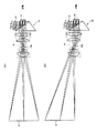
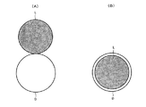
まず、図2及び図3を参照しながら、TIRプリズムを用いてレンズシフト機能をもたせる場合について説明する。図2は、TIRプリズムを用いたレンズシフトを説明するための図で、図2(A),(B)はそれぞれレンズシフト前の光路の様子、レンズシフト後の光路の様子を示す図である。また、図3(A),(B)は、それぞれ図2(A),(B)が示す状態における絞りと照明光の位置関係を示す模式図である。 First, a case where a lens shift function is provided using a TIR prism will be described with reference to FIGS. FIG. 2 is a diagram for explaining lens shift using a TIR prism, and FIGS. 2A and 2B are views showing the optical path before the lens shift and the optical path after the lens shift, respectively. . 3A and 3B are schematic views showing the positional relationship between the diaphragm and the illumination light in the states shown in FIGS. 2A and 2B, respectively.
図2(A),(B)では、TIRプリズムを用いたレンズシフトによりA位置(通常位置とする)とB位置に投射レンズ16が配置された場合の各々の光路を示している。図2(A)の状態から図2(B)の状態への遷移で示すように、コンデンサレンズ13等の照明光学系、DMD14、及びTIRプリズム15の位置を3Dプロジェクタ1の本体に固定したままで、移動機構により投射レンズ16の位置を光軸に垂直な方向にスライド移動させることによって、投射画像Sの位置を変えることができる(赤外映像の位置も同様)。
2A and 2B show respective optical paths when the
ここで重要なのは、投射レンズ16のDMD14側はテレセントリックになり、一方で、照明光も投射レンズ16に対して効率良く入射させるためDMD14で反射された後テレセントリックになるように予め設計されていることである。この状態で投射レンズ16を移動させても、主光線(この場合、光軸に対して平行)は必ず絞り16dの中心を通るため途中で光線が遮られることはない。
What is important here is that the
このことを絞り16dの断面Dにおける照明光Lの様子で説明すると、図3(A),(B)でそれぞれ示すようにA位置、B位置のいずれにおいても照明光Lは絞りの断面Dの中にあり、効率良く光を通過させることができる。 This will be described with reference to the state of the illumination light L in the cross section D of the diaphragm 16d. As shown in FIGS. 3A and 3B, the illumination light L is in the cross section D of the diaphragm at both the A position and the B position. It is inside and can transmit light efficiently.
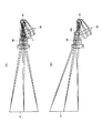
これに対してTIRプリズムを用いない光学系においては、レンズシフト機能の実現は困難となる。このことを、図4及び図5を参照しながら説明する。図4は、TIRプリズムを用いない場合のレンズシフトを説明するための図で、図4(A),(B)はそれぞれレンズシフト前の光路の様子、レンズシフト後の光路の様子を示す図である。また、図5(A),(B)は、それぞれ図4(A),(B)が示す状態における絞りと照明光の位置関係を示す模式図である。 In contrast, in an optical system that does not use a TIR prism, it is difficult to realize a lens shift function. This will be described with reference to FIGS. FIGS. 4A and 4B are diagrams for explaining the lens shift when the TIR prism is not used. FIGS. 4A and 4B are views showing the optical path before the lens shift and the optical path after the lens shift, respectively. It is. 5A and 5B are schematic views showing the positional relationship between the diaphragm and the illumination light in the states shown in FIGS. 4A and 4B, respectively.
図4(A),(B)では、TIRプリズムを用いないレンズシフトによりA位置とB位置(通常位置とする)に投射レンズ46が配置された場合の各々の光路を示している。B位置の光学系では、投射レンズ46の絞り46dはDMD44側に一番近いレンズの近くになるように設計し、照明系もこの絞り46dに対して集光するように予め設計する。これにより、照明光や照明光学系のレンズは干渉せずに、つまり光線や部品の干渉が起こらず、成立させることができる。また、通常の設計では図4(B)のように絞り46dの近くに凸レンズ(又は同様に正のパワーを持つ凹面鏡)を配置する。
4A and 4B show respective optical paths when the
このような図4(B)の状態で、コンデンサレンズ43等の照明光学系及びDMD44の位置を3Dプロジェクタ本体に固定したままで、移動機構により投射レンズ46の位置を光軸に垂直な方向にスライド移動させることによって、投射画像Sの位置を変えようとした場合、図4(A)で示すようなA位置まで投射レンズ46を移動させると、照明光や照明光学系のレンズ(凹面鏡)が固定であるため領域Iの部分で示すように干渉してしまい、成立しない。
In the state shown in FIG. 4B, the position of the
また、仮に無理な設計をして部品の干渉が防げたとしても、DMD44からの反射光は照明系やDMD44が固定であるため、図4(A)の破線のようになってしまい、絞り(46d)を効率良く通過することができなくなる。
Further, even if an unreasonable design is made to prevent interference of components, the reflected light from the
このことを絞り46dの断面Dにおける照明光Lの様子で説明すると、図5(A),(B)でそれぞれ示すようにB位置において照明光Lは絞りの断面Dの中にあるが、A位置において照明光Lは絞りの断面Dの外にあり、光を通過させることができなくなっている。
This will be described with respect to the state of the illumination light L in the cross section D of the
このように、TIRプリズムを搭載しない場合には、レンズシフト機能の実現は困難となる。つまり、DMDを用いた3Dプロジェクタにおいてレンズシフト機能を達成するためには、TIRプリズムを用いた光学系を用いればよく、必然的にTIRプリズムを用いた光学系が採用される。 As described above, when the TIR prism is not mounted, it is difficult to realize the lens shift function. That is, in order to achieve a lens shift function in a 3D projector using DMD, an optical system using a TIR prism may be used, and an optical system using a TIR prism is necessarily employed.
次に、赤外線の内部反射面15cでの反射について説明する。図1〜図3を参照しながら説明したように、本発明では投射光学系の一部として赤外線発光素子17を配置するが、この際重要になるのがTIRプリズム15の反射率特性である。この反射率特性について、図6を参照しながら説明する。図6は、図1のTIRプリズムにおける内部反射面に設けた反射防止膜の周波数特性の一例を示す図である。
Next, the reflection of infrared rays on the
可視光は、図1においてスクリーンから逆に光線追跡すれば分かるようにDMD14側に戻ってしまう。ところが、内部反射面15cにおいて通常の可視光用の反射防止膜をコーティングなどにより付けた場合でも、可視光帯域(波長400nm〜700nm程度)に対して反射率を下げるように膜厚や層数を設計するだけで、それ以外の帯域に関しては特に意図した設計を行うことはない。より具体的には、図6のグラフ61で通常の可視光用の反射防止膜を付けたガラスについて反射率の周波数特性を図示するように、赤外線は反射するため、内部反射面15cにおいて通常の可視光用の反射防止膜を付けただけでも、図1で説明したような光学系を成立させることができる。
Visible light returns to the
このように、TIRプリズム15は、内部反射面15cに可視光用の反射防止膜を設けていることが好ましい。これにより、赤外線に対しては反射膜として機能しながらも、所定の入射角より小さい場合に可視光の反射をほぼ防止することができる。
Thus, the
また、このように内部反射面15cに施した上記反射防止膜は、発光された赤外線に対して反射膜として機能するが、発光された赤外線に対する反射率を上げるように構成されていること、つまり発光された赤外線に対しては反射率を上げるような性能をもった膜であることが好ましい。より具体的には、特別に膜設計して図6のグラフ62で示すように、赤外線(ここでは波長900nmを想定)に対する反射率を上げた反射率周波数特性をもつように、上記反射防止膜を構成すればよい。
Further, the antireflection film applied to the
また、赤外線のスクリーンへの投射を効率良く行うためには、投射レンズ16の赤外線に対する透過率も重要になってくる。投射レンズ16の場合、含有するレンズの枚数が多いため、通常の可視光用の反射防止膜では透過率が落ちて使い物にならない。しかし、投射レンズ16に対しても、内部反射面15cと同様に赤外線を考慮した膜設計を行えば(特にグラフ62のような特性を持つようにすれば)、容易に透過率を上げることができる。
Further, in order to efficiently project infrared rays onto the screen, the transmittance of the
また、本発明に係る投射型表示装置としては、図1のようなTIRプリズム15を備えた構成に限らず、例えば図7や図8で示すような構成例も採用できる。図7、図8はいずれも、本発明に係る投射型表示装置の他の構成例を示す概略図で、図中、7,8は3Dプロジェクタである。以下では、3Dプロジェクタ7,8について、基本的に、図1の3Dプロジェクタ1との違いについてのみ説明を行う。
In addition, the projection display device according to the present invention is not limited to the configuration provided with the
図7に示すように、3Dプロジェクタ7はTIRプリズム70を有する。TIRプリズム70は、図1のTIRプリズム15の三角プリズム15aと同様の三角プリズム75aと、三角プリズム75bが対向配置されており、その内部反射面(境界面)75cは内部反射面15cと同様に所定の入射角より小さい角度で入射した光のみを通過させ、それ以外を全反射するようになっている。
As shown in FIG. 7, the 3D projector 7 has a
そして、3Dプロジェクタ7は、図1の3Dプロジェクタ1とは赤外線発光素子17の入射位置が異なる。TIRプリズム70の投射レンズ16への出射面側に赤外線発光素子17が設けられ、TIRプリズム70の面から赤外線が入射するように構成されている。そのため、入射した赤外線は、投射レンズ16への出射面及び内部反射面75c以外の面75dに照射される。よって、この面75dは赤外線が反射する赤外線反射面として機能するように、全反射コート又は赤外線反射コートが施されている。
The 3D projector 7 is different from the 3D projector 1 of FIG. 1 in the incident position of the infrared
図8に示すように、3Dプロジェクタ8はTIRプリズム80を有する。TIRプリズム70は、図1のTIRプリズム15の三角プリズム15aと同様の三角プリズム85aと、変形の三角プリズム85bが対向配置されており、その内部反射面(境界面)85cは内部反射面15cと同様に所定の入射角より小さい角度で入射した光のみを通過させ、それ以外を全反射するようになっている。
As shown in FIG. 8, the
そして、3Dプロジェクタ8は、図1の3Dプロジェクタ1とは赤外線発光素子17の入射位置が異なる。そして、3Dプロジェクタ8では、三角プリズム85bに、三角プリズム85aにおけるDMD14からの入射面と平行な面を設け、その面側に設けた赤外線発光素子17により、その面から赤外線が入射するように構成されている。また、三角プリズム85bには、入射した赤外線が投射レンズ16への出射面側に抜けないように、赤外線反射コートが施されて赤外線反射面として機能する斜面85dが設けられている。斜面85dは、斜面85dで反射した赤外線が内部反射面85cで反射して、投射レンズ16に向かうような角度で形成されている。
The
また、本発明に係る投射型表示装置としては、図1、図7、図8の構成例に限らず、例えば図9で示すような構成例も採用できる。図9は、本発明に係る投射型表示装置の他の構成例を示す概略図で、図中、9は3Dプロジェクタである。 Further, the projection type display device according to the present invention is not limited to the configuration examples shown in FIGS. 1, 7, and 8, and for example, a configuration example as shown in FIG. FIG. 9 is a schematic view showing another configuration example of the projection display device according to the present invention, in which 9 is a 3D projector.
3Dプロジェクタ9は、緑色用DMD14G、赤色用DMD14R、青色用DMD14Bの3枚のDMDと、3色分解・合成プリズムであるフィリップスタイプのダイクロイックプリズム90を備えた装置である。3Dプロジェクタ9は、図1の3Dプロジェクタ1と同様にTIRプリズム15における映像に使用していない面から赤外線発光素子17で発光した赤外線を入射するように構成している。
The 3D projector 9 is an apparatus that includes three DMDs, a
3Dプロジェクタ9は、ダイクロイックプリズム90で入射光をR,G,Bに分解し、図示しない制御部で各DMD14G,14R,14Bを制御することで、各色の画像を反射させ、ダイクロイックプリズム90で再合成し、TIRプリズム15及び投射レンズ16を介してスクリーン側へ出射する。そのため3Dプロジェクタ9は、図1の3Dプロジェクタ1と異なり、カラーホイール11を設ける必要がない。その他、3Dプロジェクタ9における3Dプロジェクタ1と同様の部分の説明は省略する。
The 3D projector 9 divides incident light into R, G, and B by a
以上の説明では、赤外線を採用した例を挙げたが、赤外線の代わりに、紫外線若しくは可視光線を用いる場合について説明する。紫外線若しくは可視光線を用いた場合であっても、赤外線の場合と基本的に同様に適用でき、同様の効果を奏する。よって、紫外線や可視光線の場合も同様に、投射レンズ16から投射され、被投射面であるスクリーンSで反射した光線は、アクティブシャッタ方式の3次元画像視聴用メガネにおけるアクティブシャッタの開閉に用いることができる。
In the above description, an example in which infrared rays are used has been described, but a case where ultraviolet rays or visible rays are used instead of infrared rays will be described. Even in the case of using ultraviolet light or visible light, it can be applied basically in the same manner as in the case of infrared light, and has the same effect. Therefore, similarly in the case of ultraviolet rays and visible rays, the rays projected from the
発光素子から紫外線を発光させる場合のTIRプリズムの内部反射面について、補足説明する。この場合にも、図6のグラフ61で通常の可視光用の反射防止膜を付けたガラスについて反射率の周波数特性を図示するように、紫外線は反射する。つまり、図1の構成例で説明すると、内部反射面15cにおいて通常の可視光用の反射防止膜を付けただけでも、図1で説明したような光学系を成立させることができる。紫外線を採用した場合にも同様に、内部反射面15cに施した上記反射防止膜は、発光された紫外線に対して反射膜として機能するが、発光された紫外線に対する反射率を上げるように構成されていること、つまり発光された紫外線に対しては反射率を上げるような性能をもった膜であることが好ましい。
A supplementary description will be given of the internal reflection surface of the TIR prism when ultraviolet light is emitted from the light emitting element. Also in this case, ultraviolet rays are reflected as shown in the
発光素子から可視光線を発光させる場合のTIRプリズムの内部反射面について、補足説明する。発光素子から可視光線を発光させる場合、図6のグラフ61で通常の可視光用の反射防止膜を付けたガラスについて反射率の周波数特性を図示するように、可視光線は反射しない。そのため、図1の構成例で説明すると、内部反射面15cにおいて通常の可視光用の反射防止膜を付けただけでは、図1で説明したような光学系を成立させることができない。
A supplementary description will be given of the internal reflection surface of the TIR prism in the case where visible light is emitted from the light emitting element. When the visible light is emitted from the light emitting element, the visible light does not reflect as shown in the
その場合は、内部反射面15cに施した上記反射防止膜は、発光素子から発光された可視光線に対して反射膜として機能するように、つまり可視光線のうち発光素子から発光させる波長帯域だけは反射するような反射防止膜を採用するように、構成する必要がある。このような構成の場合、映像におけるその波長帯域の光線もスクリーンSに投射されないことになることが懸念されるが、その波長帯域を極狭くしておく(並びに利用頻度の低い帯域の可視光線を発光素子から発光させるようにしておく)ことで、映像への影響を小さくすることができる。
In that case, the antireflection film applied to the
また、以上の説明では、本発明における赤外線送信等の光線送信はアクティブシャッタ方式のメガネでのアクティブシャッタの開閉に用いることを前提として説明しているが、投射レンズ16におけるズーム時の焦点調整などの他の目的でもこの赤外線等の光線を利用することや、本発明における赤外線送信等の光線送信をアクティブシャッタの開閉には用いずに焦点調整などの他の目的でのみ利用するよう構成することもできる。焦点調整について図1の構成例を挙げて補足すると、例えば赤外線発光素子17の位置若しくはその近隣に赤外線を受光する受光素子を設けておき、その受光素子で受光した赤外線の強度に基づき赤外線の広がりを検出し、その検出結果に基づき焦点調整を行えばよい。
In the above description, light transmission such as infrared transmission in the present invention has been described on the premise that it is used for opening and closing an active shutter in active shutter glasses, but focus adjustment at the time of zooming in the
ここで、発光素子についてその具体例を挙げる。赤外線発光素子17としては発光ダイオードを採用することができる。赤外線発光素子17として一般的で安価な発光ダイオードを採用することで、3Dプロジェクタ1のコストを下げることができる。また、赤外線発光素子17はレーザー素子であってもよい。レーザー素子は開口数(NA)が極めて小さいため、投射レンズ16の開口の影響は無く、効率良く投射することができる。なお、赤外線の代わりに紫外線や可視光線を採用する場合にも同様に、発光素子として発光ダイオードやレーザー素子を採用することができる。
Here, specific examples of the light emitting element are given. As the infrared
赤外線発光素子17の半値角について説明する。一般的なF値は概ねF2.5(つまりNA=0.2)である。これに対して、例えば砲弾型の発光ダイオードでは半値角10度程度のものが容易に入手可能である。NA=0.2は有効取り込み角度にするとsin−1(NA)=11.5度となり、概ね一致している。このように、投射レンズ16のF値が示す有効取り込み角度に相当する半値角をもつ赤外線発光素子を採用することで、発光ダイオードからの光を効率良く好くスクリーンに投射することが可能である。なお、赤外線の代わりに紫外線や可視光線を採用する場合にも同様に、発光素子の半値角として、投射レンズ16のF値が示す有効取り込み角度に相当する半値角を採用することが好ましい。
The half value angle of the infrared
以上、本発明に係る投射型表示装置として、反射型ミラーアレイ素子を用いて映像を表示する装置を挙げて説明したが、ミラーアレイ素子を使用しない他の光学方式を採用した装置、例えば液晶プロジェクタであっても、内部全反射プリズムを追加して上述したような発光素子の配置を採用すれば、同じ機能を達成することができる。 As described above, the projection type display apparatus according to the present invention has been described with reference to an apparatus that displays an image using a reflective mirror array element. However, an apparatus employing another optical method that does not use a mirror array element, such as a liquid crystal projector. Even so, the same function can be achieved by adding the internal total reflection prism and adopting the arrangement of the light emitting elements as described above.
ミラーアレイ素子を用いない投射型表示装置は、2つのプリズムが対向配置された内部全反射プリズムと、投射レンズとを備え、光源から発せられた光を内部全反射プリズムを介して投射レンズから投射する、3次元画像が表示可能な装置である。 A projection display device that does not use a mirror array element includes an internal total reflection prism in which two prisms are arranged to face each other and a projection lens, and projects light emitted from a light source from the projection lens through the internal total reflection prism. This is a device capable of displaying a three-dimensional image.
ミラーアレイ素子を用いない構成例として、液晶プロジェクタを例に挙げ、図1の構成例を参照しながら説明すると、DMD14を取り除き、例えばTIRプリズム15におけるDMD14が配置された側の面から、液晶表示素子を通過した光源が入射してくるように配置すればよい。若しくは、図1の構成例からDMD14を取り除き、TIRプリズム15の手前(例えばコンデンサレンズ13とTIRプリズム15との間)に液晶表示素子を設け、TIRプリズム15におけるDMD14側に図示した面を全反射するようにしておいてもよい。いずれの場合にも、発光素子は、TIRプリズム15に対して、光源(液晶を通過した光源)から発せられた光の入射面、及び投射レンズ16への出射面、とは異なる面から、赤外線等の光線を入射するように配置することが好ましい。但し、図7の構成例のように投射レンズ16への出射面から赤外線等の光線を入射するようにしてもよい。
A liquid crystal projector is taken as an example of a configuration not using a mirror array element, and will be described with reference to the configuration example of FIG. 1. The
1,7,8,9…3Dプロジェクタ、10…光源装置、11…カラーホイール、12…ロッドインテグレータ、13…コンデンサレンズ、14…DMD、14B…青色用DMD、14G…緑色用DMD、14R…赤色用DMD、15,70,80…TIRプリズム、15a,15b,75a,75b,85a,85b…三角プリズム、15c,75c,85c…内部反射面(境界面)、16…投射レンズ、17…赤外線発光素子、43…コンデンサレンズ、44…DMD、46…投射レンズ、61,62…特性グラフ、75d…面、85d…斜面、90…ダイクロイックプリズム。
1,7,8,9 ... 3D projector, 10 ... light source device, 11 ... color wheel, 12 ...
上記課題を解決するために、本発明の第1の技術手段は、2つのプリズムが対向配置された内部全反射プリズムと、投射レンズと、発光素子と、反射型ミラーアレイ素子とを備え、光源から発せられた光を前記反射型ミラーアレイ素子及び前記内部全反射プリズムを介して前記投射レンズから投射する、3次元画像が表示可能な投射型表示装置であって、前記発光素子は、前記内部全反射プリズムに光線を入射し、該光線を前記内部全反射プリズムの内部反射面で反射させ前記投射レンズを介して投射させるように、且つ、前記内部全反射プリズムに対して、前記光源から発せられた光の入射面、前記反射型ミラーアレイ素子で反射された光の入射面、及び前記投射レンズへの出射面、とは異なる面から、前記光線を入射するように、配置することを特徴としたものである。 In order to solve the above problems, a first technical means of the present invention includes an internal total reflection prism in which two prisms are arranged to face each other, a projection lens, a light emitting element, and a reflective mirror array element. A projection-type display device capable of projecting light emitted from the projection lens through the reflective mirror array element and the internal total reflection prism and capable of displaying a three-dimensional image, wherein the light-emitting element A light beam is incident on the total reflection prism, and the light beam is reflected from the internal reflection surface of the internal total reflection prism and projected through the projection lens, and is emitted from the light source to the internal total reflection prism. incident surface of resulting light incident surface of the light reflected by the reflective mirror array device, and the exit surface to the projection lens, the surface different from the, to be incident to the light beam, arranged to It is obtained by it said.
本発明の第2の技術手段は、第1の技術手段において、前記発光素子は、発光ダイオードであることを特徴としたものである。 According to a second technical means of the present invention, in the first technical means, the light emitting element is a light emitting diode.
本発明の第3の技術手段は、第1の技術手段において、前記発光素子は、レーザー素子であるとしたものである。 According to a third technical means of the present invention, in the first technical means, the light emitting element is a laser element.
本発明の第4の技術手段は、第1〜第3のいずれか1の技術手段において、前記発光素子は、前記投射レンズのF値が示す有効取り込み角度に相当する半値角をもつことを特徴としたものである。 According to a fourth technical means of the present invention, in any one of the first to third technical means, the light emitting element has a half-value angle corresponding to an effective capture angle indicated by an F value of the projection lens. It is what.
本発明の第5の技術手段は、第1〜第4のいずれか1の技術手段において、前記投射レンズから投射され、被投射面で反射した前記光線は、アクティブシャッタ方式の3次元画像視聴用メガネにおけるアクティブシャッタの開閉に用いられることを特徴としたものである。 According to a fifth technical means of the present invention, in any one of the first to fourth technical means, the light beam projected from the projection lens and reflected by the projection surface is used for viewing an active shutter type three-dimensional image. It is used for opening and closing an active shutter in glasses.
本発明の第6の技術手段は、第1〜第5のいずれか1の技術手段において、前記発光素子は、赤外線発光素子又は紫外線発光素子であり、前記内部全反射プリズムは、前記内部反射面に可視光用の反射防止膜を設けたことを特徴としたものである。
本発明の第7の技術手段は、2つのプリズムが対向配置された内部全反射プリズムと、投射レンズと、発光素子とを備え、光源から発せられた光を前記内部全反射プリズムを介して前記投射レンズから投射する、3次元画像が表示可能な投射型表示装置であって、前記発光素子は、前記内部全反射プリズムに光線を入射し、該光線を前記内部全反射プリズムの内部反射面で反射させ前記投射レンズを介して投射させるように、配置し、且つ、前記投射レンズのF値が示す有効取り込み角度に相当する半値角をもつことを特徴としたものである。
本発明の第8の技術手段は、2つのプリズムが対向配置された内部全反射プリズムと、投射レンズと、発光素子とを備え、光源から発せられた光を前記内部全反射プリズムを介して前記投射レンズから投射する、3次元画像が表示可能な投射型表示装置であって、前記発光素子は、前記内部全反射プリズムに光線を入射し、該光線を前記内部全反射プリズムの内部反射面で反射させ前記投射レンズを介して投射させるように、配置し、前記投射レンズから投射され、被投射面で反射した前記光線は、アクティブシャッタ方式の3次元画像視聴用メガネにおけるアクティブシャッタの開閉に用いられることを特徴としたものである。
本発明の第9の技術手段は、2つのプリズムが対向配置された内部全反射プリズムと、投射レンズと、赤外線発光素子又は紫外線発光素子である発光素子とを備え、光源から発せられた光を前記内部全反射プリズムを介して前記投射レンズから投射する、3次元画像が表示可能な投射型表示装置であって、前記発光素子は、前記内部全反射プリズムに光線を入射し、該光線を前記内部全反射プリズムの内部反射面で反射させ前記投射レンズを介して投射させるように、配置し、前記内部全反射プリズムは、前記内部反射面に可視光用の反射防止膜を設けたことを特徴としたものである。
本発明の第10の技術手段は、第7〜第9のいずれか1の技術手段において、前記発光素子は、前記内部全反射プリズムに対して、前記光源から発せられた光の入射面、及び前記投射レンズへの出射面、とは異なる面から、前記光線を入射するように配置することを特徴としたものである。
本発明の第11の技術手段は、第7〜第9のいずれか1の技術手段において、前記投射型表示装置は、反射型ミラーアレイ素子をさらに備え、前記光源から発せられた光を前記反射型ミラーアレイ素子及び前記内部全反射プリズムを介して前記投射レンズから投射し、前記発光素子は、前記内部全反射プリズムに対して、前記光源から発せられた光の入射面、前記反射型ミラーアレイ素子で反射された光の入射面、及び前記投射レンズへの出射面、とは異なる面から、前記光線を入射するように配置することを特徴としたものである。
According to a sixth technical means of the present invention, in any one of the first to fifth technical means, the light emitting element is an infrared light emitting element or an ultraviolet light emitting element, and the internal total reflection prism is the internal reflection surface. This is characterized in that an antireflection film for visible light is provided.
A seventh technical means of the present invention includes an internal total reflection prism in which two prisms are arranged to face each other, a projection lens, and a light emitting element, and transmits light emitted from a light source through the internal total reflection prism. A projection display apparatus that can display a three-dimensional image projected from a projection lens, wherein the light emitting element makes a light beam incident on the internal total reflection prism, and the light beam is incident on an internal reflection surface of the internal total reflection prism. It is arranged so as to be reflected and projected through the projection lens, and has a half-value angle corresponding to an effective capture angle indicated by the F value of the projection lens.
The eighth technical means of the present invention comprises an internal total reflection prism in which two prisms are arranged to face each other, a projection lens, and a light emitting element, and emits light emitted from a light source through the internal total reflection prism. A projection display apparatus that can display a three-dimensional image projected from a projection lens, wherein the light emitting element makes a light beam incident on the internal total reflection prism, and the light beam is incident on an internal reflection surface of the internal total reflection prism. The light beam that is reflected and projected through the projection lens, projected from the projection lens, and reflected by the projection surface is used for opening and closing the active shutter in active shutter type 3D image viewing glasses. It is characterized by that.
A ninth technical means of the present invention includes an internal total reflection prism in which two prisms are arranged to face each other, a projection lens, and a light emitting element which is an infrared light emitting element or an ultraviolet light emitting element, and emits light emitted from a light source. A projection-type display device capable of displaying a three-dimensional image projected from the projection lens via the internal total reflection prism, wherein the light emitting element makes a light beam incident on the internal total reflection prism, and the light beam The internal total reflection prism is disposed so as to be reflected by the internal reflection surface and projected through the projection lens, and the internal total reflection prism is provided with an antireflection film for visible light on the internal reflection surface. It is what.
According to a tenth technical means of the present invention, in any one of the seventh to ninth technical means, the light emitting element has an incident surface of light emitted from the light source with respect to the internal total reflection prism, and The light beam is disposed so as to be incident from a surface different from an exit surface to the projection lens.
According to an eleventh technical means of the present invention, in any one of the seventh to ninth technical means, the projection display device further includes a reflective mirror array element, and reflects the light emitted from the light source. Projection from the projection lens via the internal mirror reflection element and the internal total reflection prism, the light emitting element is incident on the internal total reflection prism, the incident surface of the light emitted from the light source, the reflective mirror array The light beam is disposed so as to be incident from a surface different from a light incident surface reflected by the element and a light exit surface to the projection lens.
Claims (9)
発光素子をさらに備え、該発光素子は、前記内部全反射プリズムに光線を入射し、該光線を前記内部全反射プリズムの内部反射面で反射させ前記投射レンズを介して投射させるように、配置することを特徴とする投射型表示装置。 A projection capable of displaying a three-dimensional image, comprising an internal total reflection prism in which two prisms are arranged opposite to each other and a projection lens, and projecting light emitted from a light source from the projection lens through the internal total reflection prism Type display device,
The light emitting element is further provided, and the light emitting element is disposed so that a light beam is incident on the internal total reflection prism, the light beam is reflected by an internal reflection surface of the internal total reflection prism, and is projected through the projection lens. A projection type display device characterized by that.
Priority Applications (4)
| Application Number | Priority Date | Filing Date | Title |
|---|---|---|---|
| JP2012024057A JP5044723B2 (en) | 2011-02-10 | 2012-02-07 | Projection display |
| US13/807,634 US20130100413A1 (en) | 2011-02-10 | 2012-02-09 | Projection display device |
| CN2012800020786A CN103003749A (en) | 2011-02-10 | 2012-02-09 | Projection display device |
| PCT/JP2012/052923 WO2012108486A1 (en) | 2011-02-10 | 2012-02-09 | Projection display device |
Applications Claiming Priority (3)
| Application Number | Priority Date | Filing Date | Title |
|---|---|---|---|
| JP2011026690 | 2011-02-10 | ||
| JP2011026690 | 2011-02-10 | ||
| JP2012024057A JP5044723B2 (en) | 2011-02-10 | 2012-02-07 | Projection display |
Publications (2)
| Publication Number | Publication Date |
|---|---|
| JP2012181514A true JP2012181514A (en) | 2012-09-20 |
| JP5044723B2 JP5044723B2 (en) | 2012-10-10 |
Family
ID=46638698
Family Applications (1)
| Application Number | Title | Priority Date | Filing Date |
|---|---|---|---|
| JP2012024057A Active JP5044723B2 (en) | 2011-02-10 | 2012-02-07 | Projection display |
Country Status (4)
| Country | Link |
|---|---|
| US (1) | US20130100413A1 (en) |
| JP (1) | JP5044723B2 (en) |
| CN (1) | CN103003749A (en) |
| WO (1) | WO2012108486A1 (en) |
Families Citing this family (4)
| Publication number | Priority date | Publication date | Assignee | Title |
|---|---|---|---|---|
| CN105093801A (en) * | 2014-05-22 | 2015-11-25 | 上海华博信息服务有限公司 | Monoblock stereographic projection device based on color dividing |
| CN105527717B (en) * | 2014-09-28 | 2021-03-30 | 深圳光峰科技股份有限公司 | Stereoscopic projection system |
| CN107561833B (en) * | 2017-09-13 | 2020-08-18 | 明基智能科技(上海)有限公司 | Projector with a light source |
| US11057595B2 (en) * | 2019-02-08 | 2021-07-06 | Texas Instruments Incorporated | Projection on multiple planes using a single projection unit |
Citations (5)
| Publication number | Priority date | Publication date | Assignee | Title |
|---|---|---|---|---|
| JP2000206451A (en) * | 1999-01-18 | 2000-07-28 | Minolta Co Ltd | Optical system for projector |
| JP2000206610A (en) * | 1999-01-18 | 2000-07-28 | Minolta Co Ltd | Optical system for projector |
| JP2006126501A (en) * | 2004-10-28 | 2006-05-18 | Nippon Telegr & Teleph Corp <Ntt> | Multiple eye stereoscopic display apparatus and method |
| JP2007520758A (en) * | 2004-02-05 | 2007-07-26 | ヒューレット−パッカード デベロップメント カンパニー エル.ピー. | System and method for mixing light |
| JP2010513981A (en) * | 2006-12-18 | 2010-04-30 | トムソン ライセンシング | Color gamut image projector and color gamut image projection method |
Family Cites Families (6)
| Publication number | Priority date | Publication date | Assignee | Title |
|---|---|---|---|---|
| JPH11119184A (en) | 1997-10-20 | 1999-04-30 | Fujitsu General Ltd | Automatic focusing device for liquid crystal projector |
| JP4689948B2 (en) * | 2003-06-23 | 2011-06-01 | Necディスプレイソリューションズ株式会社 | projector |
| JP3788622B2 (en) * | 2004-10-29 | 2006-06-21 | シャープ株式会社 | Optical integrator, illumination device, and projection-type image display device |
| US7651227B2 (en) * | 2005-09-13 | 2010-01-26 | Texas Instruments Incorporated | Projection system and method including spatial light modulator and compact diffractive optics |
| CN101517482B (en) * | 2006-09-14 | 2015-05-13 | 皇家飞利浦电子股份有限公司 | Laser projector with alerting light |
| JP5291900B2 (en) | 2007-07-13 | 2013-09-18 | 株式会社Suwaオプトロニクス | Internal total reflection prism and projection display |
-
2012
- 2012-02-07 JP JP2012024057A patent/JP5044723B2/en active Active
- 2012-02-09 CN CN2012800020786A patent/CN103003749A/en active Pending
- 2012-02-09 US US13/807,634 patent/US20130100413A1/en not_active Abandoned
- 2012-02-09 WO PCT/JP2012/052923 patent/WO2012108486A1/en active Application Filing
Patent Citations (5)
| Publication number | Priority date | Publication date | Assignee | Title |
|---|---|---|---|---|
| JP2000206451A (en) * | 1999-01-18 | 2000-07-28 | Minolta Co Ltd | Optical system for projector |
| JP2000206610A (en) * | 1999-01-18 | 2000-07-28 | Minolta Co Ltd | Optical system for projector |
| JP2007520758A (en) * | 2004-02-05 | 2007-07-26 | ヒューレット−パッカード デベロップメント カンパニー エル.ピー. | System and method for mixing light |
| JP2006126501A (en) * | 2004-10-28 | 2006-05-18 | Nippon Telegr & Teleph Corp <Ntt> | Multiple eye stereoscopic display apparatus and method |
| JP2010513981A (en) * | 2006-12-18 | 2010-04-30 | トムソン ライセンシング | Color gamut image projector and color gamut image projection method |
Also Published As
| Publication number | Publication date |
|---|---|
| US20130100413A1 (en) | 2013-04-25 |
| WO2012108486A1 (en) | 2012-08-16 |
| CN103003749A (en) | 2013-03-27 |
| JP5044723B2 (en) | 2012-10-10 |
Similar Documents
| Publication | Publication Date | Title |
|---|---|---|
| US9645480B2 (en) | Light source module and projection apparatus having the same | |
| JP3642267B2 (en) | Illumination optical system and projector equipped with the same | |
| TWI436150B (en) | Projector with dual projection function and its external kit | |
| NL1029702C2 (en) | Color prism and projection type image display device using it. | |
| US9316898B2 (en) | Projection apparatus | |
| JP2009538448A (en) | Digital projection system with large etendue value | |
| JP2009538447A (en) | Digital projection system with large etendue value | |
| JP3174811U (en) | Reflective optical engine | |
| US20140063466A1 (en) | Projection apparatus | |
| CN103852960A (en) | Projecting apparatus and converging module | |
| US20140218702A1 (en) | Image projection apparatus and image projection method | |
| JP5044723B2 (en) | Projection display | |
| KR20130019191A (en) | Projector with offset between projection optical system and display unit | |
| TW201833653A (en) | Projection System | |
| TWI440958B (en) | Light source system for stereoscopic projection | |
| KR20020037797A (en) | Color division device for liquid crystal display projector of single panel type | |
| US7611249B2 (en) | Projector | |
| WO2008041363A1 (en) | Projector | |
| JP6319290B2 (en) | Image projection device | |
| JP2016161746A (en) | Image display device, projector, and transmissive display device | |
| TWI444750B (en) | Color wheel module for use in a projector apparatus, projector apparatus, and method of switching display for a stereoscopic image or a flat image | |
| JP2012222421A (en) | Conference system, control method of the same, and program | |
| US20220050367A1 (en) | Optical element and projection-type display device | |
| JP2014153545A (en) | Projection type display device and spectacle | |
| US7390095B2 (en) | Projector |
Legal Events
| Date | Code | Title | Description |
|---|---|---|---|
| TRDD | Decision of grant or rejection written | ||
| A01 | Written decision to grant a patent or to grant a registration (utility model) |
Free format text: JAPANESE INTERMEDIATE CODE: A01 Effective date: 20120619 |
|
| A01 | Written decision to grant a patent or to grant a registration (utility model) |
Free format text: JAPANESE INTERMEDIATE CODE: A01 |
|
| A61 | First payment of annual fees (during grant procedure) |
Free format text: JAPANESE INTERMEDIATE CODE: A61 Effective date: 20120713 |
|
| R150 | Certificate of patent or registration of utility model |
Ref document number: 5044723 Country of ref document: JP Free format text: JAPANESE INTERMEDIATE CODE: R150 Free format text: JAPANESE INTERMEDIATE CODE: R150 |
|
| FPAY | Renewal fee payment (event date is renewal date of database) |
Free format text: PAYMENT UNTIL: 20150720 Year of fee payment: 3 |