JP2009538447A - Digital projection system with large etendue value - Google Patents
Digital projection system with large etendue value Download PDFInfo
- Publication number
- JP2009538447A JP2009538447A JP2009512081A JP2009512081A JP2009538447A JP 2009538447 A JP2009538447 A JP 2009538447A JP 2009512081 A JP2009512081 A JP 2009512081A JP 2009512081 A JP2009512081 A JP 2009512081A JP 2009538447 A JP2009538447 A JP 2009538447A
- Authority
- JP
- Japan
- Prior art keywords
- digital projector
- projector according
- light
- liquid crystal
- component color
- Prior art date
- Legal status (The legal status is an assumption and is not a legal conclusion. Google has not performed a legal analysis and makes no representation as to the accuracy of the status listed.)
- Pending
Links
- 230000003287 optical effect Effects 0.000 claims abstract description 188
- 238000005286 illumination Methods 0.000 claims abstract description 84
- 239000004973 liquid crystal related substance Substances 0.000 claims description 224
- 230000004907 flux Effects 0.000 claims description 23
- 230000010287 polarization Effects 0.000 claims description 23
- 229910052724 xenon Inorganic materials 0.000 claims description 18
- FHNFHKCVQCLJFQ-UHFFFAOYSA-N xenon atom Chemical compound [Xe] FHNFHKCVQCLJFQ-UHFFFAOYSA-N 0.000 claims description 18
- 238000000576 coating method Methods 0.000 claims description 15
- 239000010409 thin film Substances 0.000 claims description 11
- 239000011248 coating agent Substances 0.000 claims description 10
- 239000000758 substrate Substances 0.000 claims description 10
- OKTJSMMVPCPJKN-UHFFFAOYSA-N Carbon Chemical compound [C] OKTJSMMVPCPJKN-UHFFFAOYSA-N 0.000 claims description 2
- 230000000903 blocking effect Effects 0.000 claims description 2
- 239000002041 carbon nanotube Substances 0.000 claims description 2
- 229910021393 carbon nanotube Inorganic materials 0.000 claims description 2
- 239000000428 dust Substances 0.000 claims description 2
- QSHDDOUJBYECFT-UHFFFAOYSA-N mercury Chemical compound [Hg] QSHDDOUJBYECFT-UHFFFAOYSA-N 0.000 claims description 2
- 229910052753 mercury Inorganic materials 0.000 claims description 2
- 239000004038 photonic crystal Substances 0.000 claims description 2
- 238000003384 imaging method Methods 0.000 claims 1
- 239000010408 film Substances 0.000 description 54
- 238000000034 method Methods 0.000 description 42
- 239000010410 layer Substances 0.000 description 29
- 230000004075 alteration Effects 0.000 description 24
- 238000004519 manufacturing process Methods 0.000 description 20
- 230000004044 response Effects 0.000 description 17
- 239000011521 glass Substances 0.000 description 14
- 239000000463 material Substances 0.000 description 14
- 230000007246 mechanism Effects 0.000 description 14
- 238000010586 diagram Methods 0.000 description 12
- 230000000694 effects Effects 0.000 description 12
- 239000003086 colorant Substances 0.000 description 11
- 230000008901 benefit Effects 0.000 description 10
- 238000009826 distribution Methods 0.000 description 9
- 239000011159 matrix material Substances 0.000 description 9
- 230000007423 decrease Effects 0.000 description 8
- 238000011161 development Methods 0.000 description 8
- 230000015572 biosynthetic process Effects 0.000 description 7
- 230000008859 change Effects 0.000 description 7
- 238000012937 correction Methods 0.000 description 7
- 230000003595 spectral effect Effects 0.000 description 7
- 230000002411 adverse Effects 0.000 description 5
- 238000005516 engineering process Methods 0.000 description 5
- 230000006872 improvement Effects 0.000 description 5
- 238000012545 processing Methods 0.000 description 5
- 210000001747 pupil Anatomy 0.000 description 5
- 230000006798 recombination Effects 0.000 description 5
- 238000005215 recombination Methods 0.000 description 5
- 238000005452 bending Methods 0.000 description 4
- 230000009286 beneficial effect Effects 0.000 description 4
- 238000013461 design Methods 0.000 description 4
- 230000031700 light absorption Effects 0.000 description 4
- 238000000926 separation method Methods 0.000 description 4
- XUIMIQQOPSSXEZ-UHFFFAOYSA-N Silicon Chemical compound [Si] XUIMIQQOPSSXEZ-UHFFFAOYSA-N 0.000 description 3
- 238000004364 calculation method Methods 0.000 description 3
- 239000002131 composite material Substances 0.000 description 3
- 230000007547 defect Effects 0.000 description 3
- 238000000465 moulding Methods 0.000 description 3
- 230000002265 prevention Effects 0.000 description 3
- 230000008569 process Effects 0.000 description 3
- 230000009467 reduction Effects 0.000 description 3
- 238000012216 screening Methods 0.000 description 3
- 230000035945 sensitivity Effects 0.000 description 3
- 229910052710 silicon Inorganic materials 0.000 description 3
- 239000010703 silicon Substances 0.000 description 3
- NIXOWILDQLNWCW-UHFFFAOYSA-N acrylic acid group Chemical group C(C=C)(=O)O NIXOWILDQLNWCW-UHFFFAOYSA-N 0.000 description 2
- 238000013459 approach Methods 0.000 description 2
- 238000003491 array Methods 0.000 description 2
- 230000005540 biological transmission Effects 0.000 description 2
- 230000015556 catabolic process Effects 0.000 description 2
- 239000011436 cob Substances 0.000 description 2
- 238000004040 coloring Methods 0.000 description 2
- 238000006731 degradation reaction Methods 0.000 description 2
- 238000005530 etching Methods 0.000 description 2
- 230000004313 glare Effects 0.000 description 2
- 230000001771 impaired effect Effects 0.000 description 2
- 238000005259 measurement Methods 0.000 description 2
- 238000001393 microlithography Methods 0.000 description 2
- 239000012788 optical film Substances 0.000 description 2
- 238000005192 partition Methods 0.000 description 2
- 239000004033 plastic Substances 0.000 description 2
- 229920003023 plastic Polymers 0.000 description 2
- 239000004065 semiconductor Substances 0.000 description 2
- 230000000007 visual effect Effects 0.000 description 2
- ZCYVEMRRCGMTRW-UHFFFAOYSA-N 7553-56-2 Chemical compound [I] ZCYVEMRRCGMTRW-UHFFFAOYSA-N 0.000 description 1
- 208000000659 Autoimmune lymphoproliferative syndrome Diseases 0.000 description 1
- 239000004642 Polyimide Substances 0.000 description 1
- 239000004372 Polyvinyl alcohol Substances 0.000 description 1
- 238000002835 absorbance Methods 0.000 description 1
- 238000010521 absorption reaction Methods 0.000 description 1
- 230000009471 action Effects 0.000 description 1
- 229910021417 amorphous silicon Inorganic materials 0.000 description 1
- 239000006117 anti-reflective coating Substances 0.000 description 1
- 238000000149 argon plasma sintering Methods 0.000 description 1
- 201000009310 astigmatism Diseases 0.000 description 1
- 238000005266 casting Methods 0.000 description 1
- 229920002301 cellulose acetate Polymers 0.000 description 1
- 239000000919 ceramic Substances 0.000 description 1
- 238000006243 chemical reaction Methods 0.000 description 1
- 238000004140 cleaning Methods 0.000 description 1
- 238000004891 communication Methods 0.000 description 1
- 230000000295 complement effect Effects 0.000 description 1
- 150000001875 compounds Chemical class 0.000 description 1
- 230000006835 compression Effects 0.000 description 1
- 238000007906 compression Methods 0.000 description 1
- 239000004020 conductor Substances 0.000 description 1
- 229920000547 conjugated polymer Polymers 0.000 description 1
- 239000000470 constituent Substances 0.000 description 1
- 210000004087 cornea Anatomy 0.000 description 1
- 230000008878 coupling Effects 0.000 description 1
- 238000010168 coupling process Methods 0.000 description 1
- 238000005859 coupling reaction Methods 0.000 description 1
- 238000005520 cutting process Methods 0.000 description 1
- 230000002950 deficient Effects 0.000 description 1
- 230000001419 dependent effect Effects 0.000 description 1
- 230000008030 elimination Effects 0.000 description 1
- 238000003379 elimination reaction Methods 0.000 description 1
- 230000001747 exhibiting effect Effects 0.000 description 1
- 238000001914 filtration Methods 0.000 description 1
- -1 for example Substances 0.000 description 1
- 238000009499 grossing Methods 0.000 description 1
- 230000020169 heat generation Effects 0.000 description 1
- 238000007689 inspection Methods 0.000 description 1
- 230000003993 interaction Effects 0.000 description 1
- 229910052740 iodine Inorganic materials 0.000 description 1
- 239000011630 iodine Substances 0.000 description 1
- 238000012423 maintenance Methods 0.000 description 1
- 230000004048 modification Effects 0.000 description 1
- 238000012986 modification Methods 0.000 description 1
- 238000000059 patterning Methods 0.000 description 1
- 230000000737 periodic effect Effects 0.000 description 1
- 230000010363 phase shift Effects 0.000 description 1
- 239000004417 polycarbonate Substances 0.000 description 1
- 229920000515 polycarbonate Polymers 0.000 description 1
- 229910021420 polycrystalline silicon Inorganic materials 0.000 description 1
- 229920001721 polyimide Polymers 0.000 description 1
- 229920000642 polymer Polymers 0.000 description 1
- 229920006254 polymer film Polymers 0.000 description 1
- 239000002861 polymer material Substances 0.000 description 1
- 229920005591 polysilicon Polymers 0.000 description 1
- 229920002451 polyvinyl alcohol Polymers 0.000 description 1
- 238000007639 printing Methods 0.000 description 1
- 230000002250 progressing effect Effects 0.000 description 1
- 239000010453 quartz Substances 0.000 description 1
- 238000002601 radiography Methods 0.000 description 1
- 238000002310 reflectometry Methods 0.000 description 1
- 230000002787 reinforcement Effects 0.000 description 1
- 230000002040 relaxant effect Effects 0.000 description 1
- 230000003252 repetitive effect Effects 0.000 description 1
- 238000011160 research Methods 0.000 description 1
- 238000009416 shuttering Methods 0.000 description 1
- VYPSYNLAJGMNEJ-UHFFFAOYSA-N silicon dioxide Inorganic materials O=[Si]=O VYPSYNLAJGMNEJ-UHFFFAOYSA-N 0.000 description 1
- 239000002356 single layer Substances 0.000 description 1
- 239000007787 solid Substances 0.000 description 1
- 238000000638 solvent extraction Methods 0.000 description 1
- 238000001228 spectrum Methods 0.000 description 1
- 239000000126 substance Substances 0.000 description 1
- 238000006467 substitution reaction Methods 0.000 description 1
- 238000012546 transfer Methods 0.000 description 1
- 238000002834 transmittance Methods 0.000 description 1
- 239000002699 waste material Substances 0.000 description 1
Images


Classifications
-
- H—ELECTRICITY
- H04—ELECTRIC COMMUNICATION TECHNIQUE
- H04N—PICTORIAL COMMUNICATION, e.g. TELEVISION
- H04N9/00—Details of colour television systems
- H04N9/12—Picture reproducers
- H04N9/31—Projection devices for colour picture display, e.g. using electronic spatial light modulators [ESLM]
- H04N9/3141—Constructional details thereof
- H04N9/315—Modulator illumination systems
-
- G—PHYSICS
- G02—OPTICS
- G02B—OPTICAL ELEMENTS, SYSTEMS OR APPARATUS
- G02B13/00—Optical objectives specially designed for the purposes specified below
- G02B13/22—Telecentric objectives or lens systems
-
- G—PHYSICS
- G02—OPTICS
- G02B—OPTICAL ELEMENTS, SYSTEMS OR APPARATUS
- G02B27/00—Optical systems or apparatus not provided for by any of the groups G02B1/00 - G02B26/00, G02B30/00
- G02B27/10—Beam splitting or combining systems
- G02B27/1006—Beam splitting or combining systems for splitting or combining different wavelengths
- G02B27/102—Beam splitting or combining systems for splitting or combining different wavelengths for generating a colour image from monochromatic image signal sources
- G02B27/1046—Beam splitting or combining systems for splitting or combining different wavelengths for generating a colour image from monochromatic image signal sources for use with transmissive spatial light modulators
-
- G—PHYSICS
- G02—OPTICS
- G02B—OPTICAL ELEMENTS, SYSTEMS OR APPARATUS
- G02B27/00—Optical systems or apparatus not provided for by any of the groups G02B1/00 - G02B26/00, G02B30/00
- G02B27/10—Beam splitting or combining systems
- G02B27/14—Beam splitting or combining systems operating by reflection only
- G02B27/145—Beam splitting or combining systems operating by reflection only having sequential partially reflecting surfaces
-
- G—PHYSICS
- G02—OPTICS
- G02B—OPTICAL ELEMENTS, SYSTEMS OR APPARATUS
- G02B27/00—Optical systems or apparatus not provided for by any of the groups G02B1/00 - G02B26/00, G02B30/00
- G02B27/28—Optical systems or apparatus not provided for by any of the groups G02B1/00 - G02B26/00, G02B30/00 for polarising
- G02B27/283—Optical systems or apparatus not provided for by any of the groups G02B1/00 - G02B26/00, G02B30/00 for polarising used for beam splitting or combining
-
- H—ELECTRICITY
- H04—ELECTRIC COMMUNICATION TECHNIQUE
- H04N—PICTORIAL COMMUNICATION, e.g. TELEVISION
- H04N9/00—Details of colour television systems
- H04N9/12—Picture reproducers
- H04N9/31—Projection devices for colour picture display, e.g. using electronic spatial light modulators [ESLM]
- H04N9/3102—Projection devices for colour picture display, e.g. using electronic spatial light modulators [ESLM] using two-dimensional electronic spatial light modulators
- H04N9/3105—Projection devices for colour picture display, e.g. using electronic spatial light modulators [ESLM] using two-dimensional electronic spatial light modulators for displaying all colours simultaneously, e.g. by using two or more electronic spatial light modulators
-
- G—PHYSICS
- G02—OPTICS
- G02B—OPTICAL ELEMENTS, SYSTEMS OR APPARATUS
- G02B27/00—Optical systems or apparatus not provided for by any of the groups G02B1/00 - G02B26/00, G02B30/00
- G02B27/0025—Optical systems or apparatus not provided for by any of the groups G02B1/00 - G02B26/00, G02B30/00 for optical correction, e.g. distorsion, aberration
-
- G—PHYSICS
- G02—OPTICS
- G02B—OPTICAL ELEMENTS, SYSTEMS OR APPARATUS
- G02B3/00—Simple or compound lenses
- G02B3/0087—Simple or compound lenses with index gradient
-
- H—ELECTRICITY
- H04—ELECTRIC COMMUNICATION TECHNIQUE
- H04N—PICTORIAL COMMUNICATION, e.g. TELEVISION
- H04N5/00—Details of television systems
- H04N5/74—Projection arrangements for image reproduction, e.g. using eidophor
- H04N5/7416—Projection arrangements for image reproduction, e.g. using eidophor involving the use of a spatial light modulator, e.g. a light valve, controlled by a video signal
- H04N5/7441—Projection arrangements for image reproduction, e.g. using eidophor involving the use of a spatial light modulator, e.g. a light valve, controlled by a video signal the modulator being an array of liquid crystal cells
Abstract
本願で提案するディジタル映写機は、多色偏光を発生させる照明装置と、その光路上でその多色偏光から略テレセントリックな多色偏光ビームを発生させるレンズ素子と、その多色偏光ビームを複数本のテレセントリックな成分色光ビームに分割する色成分分離器と、それらの成分色光ビームを変調して複数本の変調済成分色光ビームを発生させる複数個の透光性空間光変調器と、それらの変調済成分色光ビームを共通光軸沿いに再結合して変調済多色光ビームを発生させる色成分結合器と、その変調済多色光ビームを表示画面に向ける投射レンズと、を備える。各透光性空間光変調器のエタンデュ値は、照明装置のエタンデュ値に対して15%以内の差に止め、或いは照明装置のエタンデュ値より大きな値にする。 The digital projector proposed in this application includes an illumination device that generates multi-color polarized light, a lens element that generates a substantially telecentric multi-color polarized light beam from the multi-color polarized light on the optical path, and a plurality of the multi-color polarized light beams. A color component separator for splitting into a telecentric component color light beam, a plurality of translucent spatial light modulators for modulating the component color light beams to generate a plurality of modulated component color light beams, and their modulated A color component combiner that recombines the component color light beams along a common optical axis to generate a modulated multicolor light beam; and a projection lens that directs the modulated multicolor light beam to a display screen. The etendue value of each translucent spatial light modulator is kept within 15% of the etendue value of the illuminating device, or is set to a value larger than the etendue value of the illuminating device.
Description
本発明は電子映写、特に複数枚の透光性光変調パネルを用いてフルカラー投射像を発生させる電子映写機に関する。 The present invention relates to electronic projection, and more particularly to an electronic projector that generates a full-color projection image using a plurality of translucent light modulation panels.
ディジタルシネマや類似した電子表示方式の普及に伴い、電子映写機の開発に多大な関心が集まりつつある。既存の劇場用フィルム映写機をディジタル映写機で置き換えるには高水準の性能、即ち2048×1080ピクセル以上の高解像度、広い色域、5000ルーメン以上の光束(輝度)、並びに1500:1超のフレームシーケンシャルコントラスト比を達成しなければならない。 With the widespread use of digital cinema and similar electronic display systems, there is a great deal of interest in developing electronic projectors. Replacing existing theatrical film projectors with digital projectors has a high level of performance: high resolution of 2048 x 1080 pixels, wide color gamut, luminous flux of over 5,000 lumens, and frame sequential contrast of over 1500: 1. Ratio must be achieved.
他方、液晶デバイスは種々の分野で表示デバイスとして広く活用されている(LCD)。その用途は、モノクロキャラクタディスプレイからラップトップコンピュータ用ディスプレイ、更には大型フルカラーディスプレイまで拡がっている。液晶デバイスは、周知の通り、入射光の偏向状態をピクセル単位で選択的に変調し、それらピクセルのアレイとして像を発生させるデバイスであり、そのたゆみなき改良によって低価格化、歩留まり及び信頼性の向上、並びに省電力化がとみに進んでいる。更には、その画像特性例えば解像度、応答速度及び色特性も、順調に改良されている。 On the other hand, liquid crystal devices are widely used as display devices in various fields (LCD). Its applications have expanded from monochrome character displays to laptop computer displays to large full-color displays. As is well known, a liquid crystal device is a device that selectively modulates the deflection state of incident light in units of pixels and generates an image as an array of these pixels. Improvements and power savings are progressing. Furthermore, its image characteristics such as resolution, response speed and color characteristics are also being improved smoothly.
こうした多ピクセル型液晶デバイスとしては様々な種類のものが知られているが、その基本構造は次の二構造しかない。まず、第1の基本構造はマイクロディスプレイ構造である。これは、半導体ウェハへの集積回路デバイス形成に使用されるものと類似した高密度マイクロリソグラフィ技術によって、ピクセル制御機構を形成した構造である。この構造を採る液晶デバイス即ちマイクロディスプレイデバイスには、LCOS(liquid crystal on silicon)方式の液晶デバイスやHTPS(high temperature polysilicon)を用いる透光性液晶デバイスがある。これらのデバイスでは、そのピクセル寸法が50μm未満、通常は8〜20μmのオーダになる。次に、第2の基本構造は直視型液晶パネル構造である。この構造を採るデバイスには、アモルファスシリコン(ガラス)等の透明基板上にTFT(薄膜トランジスタ)等からなるピクセル制御機構を形成した直視型TFT液晶パネルがある。このデバイスではピクセル寸法が可視寸法例えば約50μmになる。 Various types of such multi-pixel type liquid crystal devices are known, but there are only the following two basic structures. First, the first basic structure is a micro display structure. This is a structure in which a pixel control mechanism is formed by a high-density microlithography technique similar to that used for forming an integrated circuit device on a semiconductor wafer. Liquid crystal devices adopting this structure, that is, micro display devices, include LCOS (liquid crystal on silicon) liquid crystal devices and translucent liquid crystal devices using HTPS (high temperature polysilicon). In these devices, the pixel dimensions are on the order of less than 50 μm, usually 8-20 μm. Next, the second basic structure is a direct view type liquid crystal panel structure. As a device adopting this structure, there is a direct-view TFT liquid crystal panel in which a pixel control mechanism made of TFT (thin film transistor) is formed on a transparent substrate such as amorphous silicon (glass). In this device, the pixel dimensions are visible, for example about 50 μm.
第1の基本構造を採る液晶デバイスのなかでは、その小型化が容易なLCOSデバイスが一歩ぬきんでている。即ち、光変調用の液晶素材をシリコン回路支持基板上に封止した空間光変調器を、マイクロリソグラフィ技術で超高密度形成できるという長所がある。LCOSデバイスは、基本的には、液晶形成技術にCMOS(complementary metal-oxide-semiconductor)製造プロセスを組み合わせたプロセスで製造できる。 Among the liquid crystal devices adopting the first basic structure, LCOS devices that are easy to downsize are one step ahead. That is, there is an advantage that a spatial light modulator in which a liquid crystal material for light modulation is sealed on a silicon circuit support substrate can be formed with a high density by microlithography technology. The LCOS device can basically be manufactured by a process in which a liquid crystal forming technology is combined with a complementary metal-oxide-semiconductor (CMOS) manufacturing process.
LCOSデバイスには、高画質ディジタル映写機用空間光変調器として優れた点がある。例えば、最大約1.7インチ対角という扱いやすい寸法のデバイスであり、ピクセル間遊休部分が狭く、製造歩留まりも高い(1インチ=約0.025m)。LCOS技術で製造した液晶チップなら、例えば1平方インチ未満の画像発生領域で数百万個ものピクセルからなる像を発生させることができる。また、LCOSデバイスなら、割合にありきたりなレベルのシリコンエッチング技術でも、十分に高応答速度且つ高解像度なものを高速生産することができる。そのため、LCOSデバイスは、例えば背面投射型テレビジョン装置やビジネスユース映写機といった装置で、空間光変調器として用いられている。 The LCOS device has an excellent point as a spatial light modulator for a high-quality digital projector. For example, it is a device with an easy-to-handle size of up to about 1.7 inches diagonal, with a narrow inter-pixel idle portion and a high manufacturing yield (1 inch = about 0.025 m). A liquid crystal chip manufactured by LCOS technology can generate an image composed of millions of pixels in an image generation area of, for example, less than 1 square inch. In addition, an LCOS device can produce a sufficiently high response speed and high resolution at a high speed even with a silicon etching technique of a relatively high level. Therefore, LCOS devices are used as spatial light modulators in devices such as rear projection television devices and business use projectors.
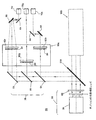
図1Aに、従来のLCOSデバイス利用電子映写機10の構成を、やや簡略化したブロック図により示す。図中、その参照符号にr,g,bの添え字が付されている部材は順に赤色,緑色,青色の変調済光ビームを発生させるための光学部品であり、どの色の光路上でも同様の光学部品が使用されている。例えば赤色光路上では、まず、赤色光源20rから出射された無変調赤色光が照度むら補正用のむら補正器(ユニフォマイザ)22rによって補正される。偏向ビームスプリッタ24rは、その無変調赤色光中の所定偏向成分を空間光変調器30rに送る。この変調器30rは、入射してくるその赤色偏光ビームを部位選択的に変調する。変調器30rからの変調出力は、一群のピクセルからなるフルカラー画像中の赤色成分を表している。この変調済赤色光ビームは光軸Or沿いにスプリッタ24rを通過してダイクロイック結合器26、例えばX−cube(商標)やPhilips(登録商標)プリズムに到達する。この結合器26は、対応する光軸Or,Og,Obに沿って到来する赤、緑、青各色の変調済光ビームを互いに結合させて変調済多色光ビームを発生させる。投射レンズ32は、この変調済多色光ビームを共通光軸Oに沿って表示画面40例えば投射スクリーン上に投射する。また、緑色光路や青色光路もこれと同様の構成である。緑色光源20gで発生した無変調緑色光ビームはむら補正器22gでの補正後に偏向ビームスプリッタ24gを介して空間光変調器30gに送られる。変調器30gで発生した変調済緑色光ビームは光軸Og沿いに結合器26に達する。同様に、青色光源20bで発生した無変調青色光ビームはむら補正器22bでの補正後に偏向ビームスプリッタ24bを介し空間光変調器30bに送られる。変調器30bで発生した変調済青色光ビームは光軸Ob沿いに結合器26に達する。
FIG. 1A shows a configuration of a conventional LCOS device-based
なお、図1Aに示した映写機10と同じくLCOSデバイスを空間光変調器として使用する電子映写機は、特許文献1(発明者:Shimomura et al.)、特許文献2(発明者:Hattori et al.)、特許文献3(発明者:Ueda)、特許文献4(発明者:Maki et al.)特許文献5(発明者:Oikawa et al.)、特許文献6(発明者:Sampsell et al.)、特許文献7(発明者:Konno et al.)等にも記載されている。
As with the
また、LCOS型液晶空間光変調器と同程度のデバイス寸法を有する空間光変調器としては、透光性液晶を利用したマイクロディスプレイデバイスがある。その一例といえるのは過日セイコーエプソン株式会社が発表したHTPSデバイスである。このデバイスは、解像度が2048×1080ピクセルで対角寸法が1.6インチのデバイスであり、水晶ウェハ上にリソグラフィエッチングで形成されている。その形成手順は従前のLCOSデバイス形成手順と同様である。 As a spatial light modulator having a device size comparable to that of an LCOS type liquid crystal spatial light modulator, there is a micro display device using a light-transmitting liquid crystal. One example is the HTPS device announced by Seiko Epson Corporation. This device is a device with a resolution of 2048 × 1080 pixels and a diagonal dimension of 1.6 inches, and is formed on a quartz wafer by lithographic etching. The formation procedure is the same as the previous LCOS device formation procedure.
次に、第2の基本構造を採る液晶デバイスとしては、液晶層を2枚の透明層例えばガラスシートで挟み込んだ液晶デバイス、即ち直視型液晶パネルと通称されラップトップコンピュータや大型表示装置の分野で広く用いられているデバイスがある。この種のデバイスは、パネル本体の他に、冷陰極蛍光管、LED(発光ダイオード)等を光源として用いるバックライトアセンブリ、並びに一群の光学部品及び光学膜を備えている。光学部品や光学膜としては、パネル本体に入射する光のむら、偏向状態、角度分布等を改質するものが使用される。TFT技術のたゆみなき進歩によって直視型液晶パネルの性能向上も進み、個々のガラス基板面に形成できるトランジスタの個数及び密度が飛躍的に増大向上したほか、薄くて応答時間が短い液晶層を形成できる新種の液晶素材が開発されたため、直視型液晶パネルの解像度や応答速度は高まっている。即ち、より大型でより応答速度、解像度及び発色性能が高い直視型液晶パネルが生み出され、ディスプレイデバイスとして広く普及しつつある。ただ、その開発の狙いは主にデスクトップディスプレイや家庭用テレビジョン装置の性能向上に置かれている。 Next, as a liquid crystal device adopting the second basic structure, a liquid crystal device in which a liquid crystal layer is sandwiched between two transparent layers, for example, glass sheets, that is, a so-called direct-view type liquid crystal panel, which is commonly called a laptop computer or a large display device, is used. There are widely used devices. In addition to the panel body, this type of device includes a cold cathode fluorescent tube, a backlight assembly using an LED (light emitting diode) or the like as a light source, and a group of optical components and optical films. As the optical component or optical film, one that modifies the unevenness of light incident on the panel body, the deflection state, the angular distribution, and the like is used. Through continuous progress in TFT technology, the performance of direct-view liquid crystal panels has also improved, dramatically increasing the number and density of transistors that can be formed on the surface of individual glass substrates, and forming a thin liquid crystal layer with a short response time. Due to the development of new types of liquid crystal materials, the resolution and response speed of direct view liquid crystal panels are increasing. That is, a direct-view type liquid crystal panel having a larger size and higher response speed, resolution, and color development performance has been created and is becoming widespread as a display device. However, its development is mainly aimed at improving the performance of desktop displays and home television devices.
前掲の各文献にも記されている通り、劇場向け映写機の開発では第1の基本構造を採るLCOS型液晶空間光変調器に注目及び努力が集中しており、第1の基本構造を採る直視型TFT液晶パネルにはさほど注意や努力が払われていない。これにはかなり自明な理由が多数ある。例えば、映写機の小型化には使用部品の小型化が必要だ、という観点がある。この観点からは、LCOSデバイス、DMD(digital micromirror device)等といったマイクロディスプレイデバイスを小型空間光変調器として採用することが、必須になってくる。例えばSMPTE(Society of Motion Picture and Television Engineers)でまとめたディジタルシネマ規格によれば、大型映写スクリーン上への映写に当たっては2048×1080ピクセル、4096×2160ピクセル又はそれ以上での高解像度表示を行わねばならない。高度にコンパクトなピクセル配置及び8〜20μm程度の小さなピクセル寸法を有するLCOSデバイスならば、それを1個使用するだけで、大型映写スクリーン上にこの規格に則った解像度で画像を映写することができる。また、直視型液晶パネルではなくLCOSデバイスに関心が寄せられるのはなぜか、という点では、後者の方が現状では性能的に優れているという理由がある。例えばその応答時間が4msec未満と短いこと、色域が広いこと、コントラスト比が2000:1を上回ること等である。なかでも反射性LCOSデバイスは、放熱器付なら照明光のエネルギ密度が多少高くても使用でき、70%超のNA(開口率)を実現でき、また原則として色フィルタアレイやバックライトアセンブリも必要ない。 As described in the above-mentioned documents, attention and effort are concentrated on the LCOS type liquid crystal spatial light modulator that adopts the first basic structure in the development of the projector for the theater, and the direct view that adopts the first basic structure. Not much attention and effort has been paid to the type TFT liquid crystal panel. There are many obvious reasons for this. For example, there is a viewpoint that miniaturization of projectors requires miniaturization of parts used. From this point of view, it is indispensable to adopt a micro display device such as an LCOS device or DMD (digital micromirror device) as a small spatial light modulator. For example, according to the digital cinema standard summarized by SMPTE (Society of Motion Picture and Television Engineers), high-resolution display at 2048 × 1080 pixels, 4096 × 2160 pixels or more is required for projection on a large projection screen. Don't be. An LCOS device with a highly compact pixel arrangement and a small pixel size on the order of 8-20 μm can project an image on a large projection screen with a resolution according to this standard by using only one of them. . In addition, there is a reason that the latter is superior in terms of performance at present in terms of why the LCOS device is interested rather than the direct-view type liquid crystal panel. For example, the response time is as short as less than 4 msec, the color gamut is wide, and the contrast ratio exceeds 2000: 1. In particular, reflective LCOS devices can be used with radiators even if the energy density of the illumination light is somewhat high, can achieve NA (aperture ratio) of over 70%, and in principle need a color filter array and backlight assembly. Absent.
更に、映写機開発の労力をますます小型空間光変調器の開発に向けさせている事情として、置き換え対象たるフィルムとの寸法相性がある。即ち、LCOS(又はDMD)型液晶空間光変調器上に形成される画像発生領域のサイズが、映写用フィルムプリント上の映写単位たる画像フレームのサイズに近いという事情である。映写機用光学系の設計を若干でも容易にするのに、例えば既存のフィルム式映写機用光学系からの設計変更という手段が使えるかもしれない。ただ、LCOS(又はDMD)型液晶空間光変調器に対するこうした期待は、画像発生部品はより小さい方がよい、という一部技術者の思いこみと相俟って生じているものである。即ち、開発者自身の思いこみがありきたりな根拠や需要と軌を一にしているため開発者達の間に臆断が生じ、小型なLCOS(又はDMD)型液晶空間光変調器が高画質ディジタル映写用画像発生部品として最適であるかの如く思われている。 In addition, one of the reasons for increasing the effort of developing projectors toward the development of small spatial light modulators is the dimensional compatibility with the film to be replaced. That is, the size of the image generation area formed on the LCOS (or DMD) type liquid crystal spatial light modulator is close to the size of the image frame as a projection unit on the projection film print. In order to make the design of the projector optical system a little easier, for example, a means of design change from the existing film projector optical system may be used. However, this expectation for the LCOS (or DMD) type liquid crystal spatial light modulator is combined with the thought of some engineers that the image generating component should be smaller. In other words, the developer's own thoughts and demands are in line with the demands, and there is a gap between the developers, and a small LCOS (or DMD) liquid crystal spatial light modulator is used for high-quality digital projection images. It seems to be the best as a generating part.
また、ウェハ利用型のデバイス構造を採るため小型化及び応答速度向上が可能であるとはいえ、LCOS(又はDMD)型液晶空間光変調器には、大画面映写機での使用を妨げる本質的な問題点も幾つかある。特に問題なのはその輝度及び効率が低いことである。画像技術の分野で熟練を積まれた方々(いわゆる当業者)には周知の通り、およそどのような光学系でも幾何光学的条件に拘束されるものであり、またそうした条件の一つとしてはエタンデュ値乃至ラグランジュ不変量によって記述される条件がある。エタンデュ値とは光学系内の所与平面上での開口寸法を許容立体角に乗じたものであり、整合対称光学系ではこの積はラグランジュ不変量と同じ値になる。不整合光学系や非対称光学系ではこの積に拡がりがでるので、エタンデュ値としては、その光学系を光が透過できる最小値を使用する。この点については非特許文献1を参照されたい。
In addition, although it is possible to reduce the size and improve the response speed by adopting a wafer-based device structure, the LCOS (or DMD) type liquid crystal spatial light modulator essentially prevents use in a large screen projector. There are also some problems. Of particular concern is its low brightness and efficiency. As is well known to those skilled in the field of image technology (so-called those skilled in the art), almost any optical system is constrained by geometric optical conditions, and one such condition is Etendue. There are conditions described by values or Lagrange invariants. The Etendue value is a value obtained by multiplying an allowable solid angle by an aperture size on a given plane in the optical system. In a matched symmetric optical system, this product is the same value as a Lagrange invariant. The mismatched optical system and the asymmetric optical system spread out in this product. Therefore, the minimum value at which light can pass through the optical system is used as the etendue value. Refer to
エタンデュ値やその代替量たるラグランジュ不変量は、ある直感的に明らかな原理についての数値的指標になる。その原理とは、ある寸法の開口を通過しうる光の量はその開口の寸法で制限される、という原理である。エタンデュ値の定義から明らかなように、小開口からの出射で高輝度を実現するには光出射範囲を角度的に拡げねばならないが、広角に拡がる照明光を扱える光学系は複雑且つ高価になる。この問題について触れた文献としては特許文献8(名称:テレセントリック光学系を用いた投射装置(Projection Apparatus Using Telecentric Optics);発明者:Cobb et al.;特許権者:本願出願人)、特許文献9(名称:空間光変調器を用いた投射装置(Projection Apparatus Using Spatial Light Modulator);発明者:Cobb)並びに特許文献10(名称:リレイレンズ及びダイクロイック結合器を伴う空間光変調器を用いた投射装置(Projection Apparatus Using Spatial Light Modulator with Relay Lens and Dichroic Combiner);発明者:Cobb et al.)があるが、これらはいずれも高密度LCOS液晶デバイスを使用した電子映写機についてのものであり、その対策法も、十分な出射光量が得られるよう空間光変調器のNAを高くすることで光学系内の要所で角度条件を緩和する、というものである。 The Etendue value and its substitution, the Lagrange invariant, are numerical indicators of some intuitive principle. The principle is that the amount of light that can pass through an aperture of a certain size is limited by the size of the aperture. As is clear from the definition of the etendue value, in order to achieve high brightness by emission from a small aperture, the light emission range must be expanded angularly, but an optical system that can handle illumination light that expands to a wide angle is complicated and expensive. . Patent documents 8 (name: Projection Apparatus Using Telecentric Optics; Inventor: Cobb et al .; Patentee: applicant of the present application), Patent Document 9 (Name: Projection Apparatus Using Spatial Light Modulator); Inventor: Cobb) and Patent Document 10 (Name: Projection Apparatus Using Spatial Light Modulator with Relay Lens and Dichroic Coupler ( Projection Apparatus Using Spatial Light Modulator with Relay Lens and Dichroic Combiner); Inventor: Cobb et al.), These are all about electronic projectors using high-density LCOS liquid crystal devices, and their countermeasures are also The angle condition is relaxed at a key point in the optical system by increasing the NA of the spatial light modulator so as to obtain a sufficient amount of emitted light.
液晶デバイスには、更に、角度的に拡がった変調光を発生させにくいという問題もある。照明光を広角にすることでそうした変調光を発生させようとすると、液晶デバイスを用いた画像発生の仕組みや液晶素材に備わる複屈折性が災いし、発生する変調光のコントラスト比や色特性が悪くなる。コントラスト比を十分なレベルまで高めようとすると、往々にして液晶デバイス近傍等に何個か補償器を組み込まねばならなくなるが、そのようにすると映写機の複雑さと価格が更に増してしまう。なお、特許文献11(名称:LCD用補償膜(Compensation Films for LCDs);発明者:Ishikawa et al.;特許権者:本願出願人)には、ワイヤグリッド偏光器及び液晶デバイスにて発生する角度偏向効果を補償するため補償器を用いる例が記載されている。このように、LCOS液晶デバイス、HTPSデバイス、DMD等といったマイクロディスプレイデバイスには、部品の寸法や光路の幾何形状に関する問題がある。 The liquid crystal device also has a problem that it is difficult to generate modulated light that is spread in an angle. If you try to generate such modulated light by widening the illumination light, the mechanism of image generation using the liquid crystal device and the birefringence of the liquid crystal material will be damaged, and the contrast ratio and color characteristics of the generated modulated light will be affected. Deteriorate. In order to increase the contrast ratio to a sufficient level, it is often necessary to incorporate several compensators in the vicinity of the liquid crystal device, but doing so further increases the complexity and cost of the projector. In Patent Document 11 (name: Compensation Films for LCDs; Inventor: Ishikawa et al .; Patentee: Applicant), an angle generated in a wire grid polarizer and a liquid crystal device. An example of using a compensator to compensate for the deflection effect is described. As described above, microdisplay devices such as LCOS liquid crystal devices, HTPS devices, DMDs, and the like have problems related to component dimensions and optical path geometry.
画像発生部品には、開口面積や光の角度のほかにエネルギ密度制限という問題もある。小型空間光変調器特に液晶空間光変調器が部品レベルで受け入れうるエネルギ密度は低く、その上限を超える輝度を得ようとすると変調器自体が損傷しかねない。通常、無機アライメント層付LCOSデバイスではエネルギ密度の上限が15W/cm2程度であり、従ってその直径が1.3インチのLCOSデバイスなら約15000ルーメンが出射光束の上限になる。とりわけ熱ビルドアップを防がないと画像にむらや色収差が発生し、その変調器及び関連部品の寿命が損なわれる。即ち、熱ビルドアップが生じると例えば吸光性偏光器の挙動が顕著に劣悪になるので、空間光変調器本体に対する効果的な除熱機構や、関連する光学部品に対する注意深い技術的検討が必要になる。ただ、それらはやはり、コスト増及び光学系複雑化の原因になる。 In addition to the aperture area and the light angle, the image generating component also has a problem of energy density limitation. A small spatial light modulator, particularly a liquid crystal spatial light modulator, has a low energy density that can be accepted at the component level, and if the luminance exceeding the upper limit is obtained, the modulator itself may be damaged. Usually, the upper limit of the energy density is about 15 W / cm 2 in the LCOS device with an inorganic alignment layer, and therefore about 15000 lumens is the upper limit of the emitted light beam in the case of the LCOS device having a diameter of 1.3 inches. In particular, if the thermal buildup is not prevented, unevenness and chromatic aberration occur in the image, and the lifetime of the modulator and related parts is impaired. That is, when thermal build-up occurs, for example, the behavior of the light absorbing polarizer is remarkably deteriorated. Therefore, an effective heat removal mechanism for the spatial light modulator body and careful technical examination of the related optical components are required. . However, they still cause an increase in cost and complexity of the optical system.
この問題に絡んで重視すべきことは、ウェハ型デバイス製造工程をより微細化して製造歩留まり及び製造効率を高めよう、という流れが連綿と続いていることである。いうまでもなく、液晶空間光変調器の開発もこの線で進められ、更なるコンパクト化及び小型化が追求されている。これまでに開発された変調器のなかには、前世代変調器の約1.3インチ対角に比べ劇的に小さな約0.5インチ対角のものもある。しかしながら、エタンデュ値乃至ラグランジュ不変量やエネルギ密度に関し、前述した問題点があるので、これ以上に小型化を進めてしまうと、液晶デバイスを利用した大画面劇場用映写機の開発にはむしろ支障になる。それは、変調器の小型化が進むにつれ加速度的に、所要輝度を得ることが難しくなるからである。更に、ピクセルが極端に小さくなり例えば8〜20μm程度になると、よりピクセルが大きいデバイスでは画質に影響を与えないような小さな欠陥、例えば高々1〜2μm程の欠陥でも、画質に対して大きな影響を与えるようになるので、欠陥の大きさや製造歩留まりも問題になる。 What should be emphasized in connection with this problem is that the trend of further miniaturizing the wafer type device manufacturing process to increase the manufacturing yield and manufacturing efficiency continues. Needless to say, liquid crystal spatial light modulators are also being developed along this line, and further downsizing and downsizing are being pursued. Some modulators developed to date are about 0.5 inches diagonal, which is dramatically smaller than the previous generation modulators about 1.3 inches diagonal. However, there are the above-mentioned problems concerning etendue values, Lagrange invariants, and energy density, so if further downsizing is made, it will rather hinder the development of a large-screen theater projector using liquid crystal devices. . This is because it becomes difficult to obtain the required luminance in an accelerated manner as the modulator becomes smaller. Furthermore, when the pixel becomes extremely small, for example, about 8 to 20 μm, even a small defect that does not affect the image quality on a device having a larger pixel, for example, a defect of about 1 to 2 μm at most, has a large influence on the image quality. Therefore, the size of defects and the production yield are also problems.
液晶デバイスには、更に、こうしたエタンデュ値由来の条件以外にNA上の制限がつきものである。通常、液晶デバイスの開口はブラックマトリクスをパターニングすることによって形成されており、そのブラックマトリクスは個々のピクセルの制御用トランジスタに対し入射光が悪影響を及ぼしコントラスト比が下がるのを防いでいる。しかし、HTPSデバイスのような透光性デバイスでは、ブラックマトリクスがあると実効透光率が下がり、LCOSデバイスの約90%より低い60%以下までNAが下がる。透光性パネルであってもその寸法が十分大きく従ってピクセル面積が大きければ、多少NAが低くても十分な輝度を提供できるが、HTPSデバイスのようなマイクロディスプレイデバイスではピクセル寸法が小さすぎ、NAが低いと大きな問題、例えば画質上の問題になる。即ち、その幅が約40フィート以上もあるのが普通の劇場用スクリーンのサイズに合わせ画像を拡大すると、HTPSデバイス程度のNAでは、スクリーンドア偽像が目立って発現してくる(1フィート=約0.30m)。加えて、HTPSアレイ規模のマイクロディスプレイデバイスではその活性領域も狭いので、光源からその開口に入射する光を吸収して発熱し、空間光変調器本体やその関連部品の性能に対し更なる悪影響が及ぶことがある。従って、この種のデバイスを好適に使用できるのは、狭所向けディジタル映写機例えば検査室向け映写機やビジネスプレゼンテーション用映写機だけであり、扱える光量が取扱所要光量に対して不足するため一般の劇場では使用できない。即ち、劇場で使用するには、普通のサイズのスクリーンでも最低10000ルーメンの光量が必要であり、最大サイズのスクリーンなら最低60000ルーメンの出射光束が必要になる。この条件は厳しく、液晶型マイクロディスプレイデバイス例えば2インチ対角未満のLCOSデバイスやHTPSデバイスで達成できる物理的限界を超克している。この限界を乗り越えるには、熱その他の要因への並はずれた補償手段が必要になり、それは映写機価格をひときわ押し上げる要因になる。 In addition to the conditions derived from such etendue values, liquid crystal devices are also subject to NA restrictions. Usually, the opening of the liquid crystal device is formed by patterning a black matrix, and the black matrix prevents incident light from adversely affecting the control transistors of the individual pixels and lowering the contrast ratio. However, in a translucent device such as an HTPS device, if there is a black matrix, the effective transmissivity decreases, and the NA decreases to 60% or less, which is lower than about 90% of the LCOS device. Even if a light-transmitting panel is sufficiently large and therefore has a large pixel area, it can provide sufficient luminance even if the NA is somewhat low. However, in a micro display device such as an HTPS device, the pixel size is too small and the NA is small. If it is low, it becomes a big problem, for example, a problem on image quality. In other words, when the image is enlarged to fit the size of a normal theater screen whose width is about 40 feet or more, a screen door false image appears conspicuously in NA as high as an HTPS device (1 foot = about 0.30 m). In addition, since the active region of an HTPS array-scale microdisplay device is narrow, it absorbs light incident on the aperture from the light source and generates heat, further adversely affecting the performance of the spatial light modulator body and related components. There may be. Therefore, this type of device can only be used suitably for digital projectors for narrow spaces, such as projectors for laboratory use and projectors for business presentations. Can not. That is, for use in a theater, a light of at least 10,000 lumens is required even for a normal size screen, and a light flux of at least 60000 lumens is required for a maximum size screen. This condition is severe and overcomes the physical limitations achievable with liquid crystal microdisplay devices such as LCOS devices less than 2 inches diagonal and HTPS devices. Overcoming this limit requires extraordinary compensation for heat and other factors, which can significantly increase projector prices.
また、従来の映写機用光学系では、集光によってそのビーム幅をできるだけ細めてから、照明光ビームを色成分分離器や変調器に送り込むのが普通であった。こうしたやり方が好まれていたのは、レンズ、フィルタ、偏光器等の光学部品を小型化でき、光の補正、分岐、変調及び再結合に関わる光学系全体をコンパクトにまとめられるためである。例えば図1Aに示した従来のLCOS利用映写機でも、照明先たるLOCS型液晶空間光変調器が小さいため照明光ビームを細く絞る必要がある。 Further, in conventional projector optical systems, it has been usual to narrow the beam width as much as possible by condensing and then send the illumination light beam to a color component separator or modulator. This method is preferred because the optical components such as lenses, filters, and polarizers can be miniaturized and the entire optical system related to light correction, branching, modulation, and recombination can be compactly assembled. For example, even in the conventional LCOS projector shown in FIG. 1A, the illumination light beam needs to be narrowed down because the LOCS liquid crystal spatial light modulator that is the illumination destination is small.
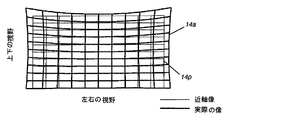
しかし、そのようにすると、従来のLCOS利用映写機では輝度上の問題が大きくなる。即ち、前述の通りラグランジュ不変量による制限が課されているので、ビーム幅(ビーム横断面積)が小さいと十分な光量を得ることができない。照明光ビームを広角にしたとしても、色成分分離器や色成分結合器で使用しているダイクロイック被覆(波長選択膜)によるスペクトルエッジシフト効果が角度の関数であるため、画質の低下が生じてしまう。光路上の要所で光ビームを拡幅/狭窄するにしても、各色光路上で照明光ビーム及び変調済光ビームを拡幅/狭窄するための補正用光学部品例えばレンズを差し挟まねばならない分、光学系の構成が複雑になりコストがかかってしまう。例えば図1Bに示す従来技術では、広い角度範囲から入射するようそのLCOSデバイスへの入射光を集光する一方、その前後で角度的な拡がりを抑えてダイクロイック被覆のスペクトルエッジシフト効果を減らしまた応答速度を高めている。しかし、こうした従来の光学系を利用し高輝度カラー電子映写機を実現しようとしても、使用する光学部品が多い分出射光が減り、画質と出射光強度のトレードオフが生じるので、それはかなり難しいことである。従来技術ではこのトレードオフを避けることができない。 However, in such a case, the luminance problem becomes large in the conventional LCOS projector. That is, as described above, since the restriction by the Lagrange invariant is imposed, a sufficient amount of light cannot be obtained if the beam width (beam crossing area) is small. Even if the illumination light beam is wide-angled, the spectral edge shift effect of the dichroic coating (wavelength selective film) used in the color component separator and color component combiner is a function of angle, resulting in degradation of image quality. End up. Even if the light beam is widened / squeezed at an important point on the optical path, a correction optical component, for example, a lens, must be sandwiched between the optical light and the modulated light beam on each color optical path. The system configuration is complicated and expensive. For example, in the prior art shown in FIG. 1B, the incident light to the LCOS device is focused so as to be incident from a wide angular range, while the angular spread is suppressed before and after that to reduce the spectral edge shift effect of the dichroic coating and to respond. Increasing speed. However, even when trying to realize a high-luminance color electronic projector using such a conventional optical system, the emitted light is reduced by the amount of optical components used, and a trade-off between image quality and emitted light intensity occurs, which is quite difficult. is there. This trade-off cannot be avoided with the prior art.
また、ローエンドのLCOS利用電子映写機は既に広く市販されている。市販されているのは、その出射光束が1000ルーメン程もあればよい家庭用背面投写型テレビジョン装置や、ほどほどの光学効率及び出射光束並びに許容できる画質を低コストで実現できればよいビジネスプレゼンテーション用映写機である。画面輝度及び画質をフィルム式映写機並みに高めるよう求められてはいるが、それを達成するには厳しいトレードオフを克服しなければならない。まず、10%未満という低い光学効率を補うため、従来の液晶利用電子映写機では非常に明るい照明装置を用いる必要がある。例えば三洋電機株式会社製の映写機PLVHD20では、セイコーエプソン株式会社製の1.6インチ対角HTPS液晶チップを用いた液晶マイクロディスプレイデバイスを、300ワットUHPランプを4個も用いて照明し、その変調光の光束を7000ルーメンに高めている。低出力ランプを複数個用いるのはエタンデュ値を大きくすることなく出射光強度を高めるためである。即ち、アークランプの出力を大きくするためそのアークギャップを拡げると、出力だけでなくエタンデュ値(照明装置側エタンデュ値)も増大し、しかもその増大が出力増大より急に進むためである。同じ理由で、ソニー株式会社製の映写機SRX−R110でも、1.55インチサイズのLCOS型マイクロディスプレイデバイスを2個の高価な2.0kW光源で照明して10000ルーメンの出射光束を達成している。しかしながら、これらの映写機はいずれもそのランプ出力が液晶空間光変調器に対し不釣り合いで、熱、コスト及び光源寿命に関わる問題をもたらしている。例えば、高エネルギ密度に耐え所要輝度を達成しようとすると、照明光路上及び変調光路上に設ける光学部品が高価なものになってしまう。安価な吸光性偏光器ではなくて高価なワイヤグリッド偏光器を用いざるを得ない、といった具合である。このように、従来の映写機では、所要出射光束を得るのに、高性能だが高価な光学部品を使用するか、或いは安価だが低性能な光学部品を複数個使用するという途を採るほかなかったが、いずれもその信頼性が低くコストが嵩むものであった。 Low-end LCOS-based electronic projectors are already widely available on the market. Commercially available rear projection television apparatuses that require an output light beam of about 1000 lumens, and projectors for business presentations that can achieve reasonable optical efficiency, output light beam, and acceptable image quality at low cost. It is. While demands have been made to increase screen brightness and image quality to the level of film projectors, severe trade-offs must be overcome to achieve that. First, in order to compensate for the low optical efficiency of less than 10%, it is necessary to use a very bright illumination device in a conventional liquid crystal electronic projector. For example, in the projector PLVHD20 manufactured by Sanyo Electric Co., Ltd., a liquid crystal microdisplay device using a 1.6-inch diagonal HTPS liquid crystal chip manufactured by Seiko Epson Corporation is illuminated using four 300-watt UHP lamps and modulated. The luminous flux of light is increased to 7000 lumens. The reason for using a plurality of low-power lamps is to increase the intensity of emitted light without increasing the etendue value. That is, if the arc gap is widened in order to increase the output of the arc lamp, not only the output but also the etendue value (illuminating device side etendue value) increases, and the increase proceeds more rapidly than the increase in output. For the same reason, the projector SRX-R110 manufactured by Sony Corporation has achieved a luminous flux of 10,000 lumens by illuminating a 1.55-inch LCOS microdisplay device with two expensive 2.0 kW light sources. . However, each of these projectors has a lamp output that is disproportionate to the liquid crystal spatial light modulator, resulting in problems related to heat, cost, and light source life. For example, if an attempt is made to withstand a high energy density and achieve the required luminance, optical components provided on the illumination optical path and the modulation optical path become expensive. For example, an expensive wire grid polarizer must be used instead of an inexpensive absorptive polarizer. As described above, in the conventional projector, there is no choice but to use a high-performance but expensive optical component or a plurality of inexpensive but low-performance optical components to obtain the required emitted light beam. In either case, the reliability was low and the cost was high.
更に、電子映写機では、個々の成分色乃至スペクトル帯域を別々に変調し、変調後の光を再結合してフルカラー画像を生成するのが普通である。変調済の光ビームを色別に設けた投射光学系例えば投射レンズアセンブリで個々に投射し投射先画面上で直に再結合させてもよいし、変調後に光ビーム同士を再結合させ1個の投射レンズアセンブリで投射するようにしてもよい。後者の場合には、各成分色間で光路長を等しくしなければならない。従来における光路長等化方式としては、特許文献12(名称:光路長等化型表示システム(Display System with Equal Path Lengths);発明者:McKechnie et al.)に記載のものや、特許文献13(名称:成分色間光路長等化型三連レンズ式投射表示装置(Triple-Lens Type Projection Display with Uniform Optical Path Lengths for Different Color Components);発明者:Tiao et al.)に記載のものがある。 Further, in an electronic projector, it is common to individually modulate individual component colors or spectral bands and recombine the modulated light to generate a full color image. A modulated optical beam may be individually projected by a projection optical system, for example, a projection lens assembly provided for each color, and directly recombined on the projection target screen, or the light beams may be recombined after modulation to produce a single projection. You may make it project with a lens assembly. In the latter case, the optical path lengths must be equal between the component colors. Conventional optical path length equalization methods include those described in Patent Document 12 (name: Display System with Equal Path Lengths; Inventor: McKechnie et al.), And Patent Document 13 ( Name: Triple-Lens Type Projection Display with Uniform Optical Path Lengths for Different Color Components; Inventor: Tiao et al.
以上のように、LCOSデバイスやHTPSデバイスといった液晶マイクロディスプレイデバイスを用い高輝度映写機を実現することは困難であるので、大きな直視型液晶パネルを用い実現することを考えた方がよい。直視型液晶パネルの解像度、コントラスト比及び応答速度はかなり改善されてきており、以前に比べたらマイクロディスプレイデバイスに代替できる見込みが強まっている。ただ、現在製造されている直視型液晶パネルはフラットパネルディスプレイ用のものであるので、そのまま高輝度映写機で使用することは望ましくない。例えば、TFT液晶のパネルに吸光性偏光器を直付けした品が広く製造されているが、これは画質に悪影響がある。即ち、吸光性偏光器では入射光のエネルギのうち約20%以上も吸収し発熱するので、その熱によって液晶層が加熱されときとしてパネル全面にむらやコントラスト比損失が発生する。 As described above, since it is difficult to realize a high brightness projector using a liquid crystal micro display device such as an LCOS device or an HTPS device, it is better to consider using a large direct view liquid crystal panel. The resolution, contrast ratio, and response speed of the direct-view liquid crystal panel have been improved considerably, and the possibility of substituting for a micro display device is increasing compared with before. However, since the direct-view type liquid crystal panel currently manufactured is for a flat panel display, it is not desirable to use it as it is in a high brightness projector. For example, a product in which a light absorbing polarizer is directly attached to a TFT liquid crystal panel is widely manufactured, which has an adverse effect on image quality. That is, the light absorbing polarizer absorbs about 20% or more of the incident light energy and generates heat, and when the liquid crystal layer is heated by the heat, unevenness of the entire panel and loss of contrast ratio occur.
同様に、専らデスクトップモニタやテレビジョン装置で用いられる高速高コントラスト比液晶パネルには、多くの場合吸光性色フィルタアレイが内蔵されている。このアレイはこの用途で要求される発色性能を実現のに役立つが、同じく吸光により発熱してむら乃至偽像を発生させデバイスに損傷も与える点で、高輝度映写機用としては望ましくない。更に、医療用高解像度白黒表示パネルもあるが、放射線撮影で得られた静止画の表示を主たる用途としているため普通は低応答速度である。また、その応答速度を高めて動画をより好適に表示できるようにした新種の表示パネルも開発されており、なかでも応答時間を2msオーダまで短縮できるOCB(登録商標)モードがその代表格であるが、これはフラットパネルディスプレイを念頭に置いて開発されたものである。フィールドシーケンシャルカラー照明を実行して直視型液晶パネルのバックライトコストを抑えることや、高価な色フィルタアレイを不要にしてパネルコストを抑えることができるとはいえ、高輝度ディジタル映写機での使用はまだ可能になっていない。 Similarly, high-speed, high-contrast ratio liquid crystal panels used exclusively for desktop monitors and television devices often incorporate a light-absorbing color filter array. This array helps to achieve the color development performance required for this application, but is also undesirable for high-intensity projectors because it also generates heat due to light absorption to generate unevenness or false images and damage the device. In addition, there is a high-resolution monochrome display panel for medical use, but since it is mainly used to display still images obtained by radiography, it usually has a low response speed. In addition, a new type of display panel has been developed that can increase the response speed and display a moving image more suitably. Among them, the OCB (registered trademark) mode that can shorten the response time to the order of 2 ms is a typical example. However, it was developed with a flat panel display in mind. Although field sequential color illumination can be implemented to reduce the backlight cost of direct-view LCD panels and panel costs can be reduced by eliminating the need for expensive color filter arrays, they are still not used in high-brightness digital projectors. Not possible.
直視型TFT液晶パネルを代わりに用いた映写機は他にも何種類か提案されているが、それらの多くは特定用途専用のものであり、ハイエンドディジタル映写機向けに開発されたものではない。例えば特許文献14(発明者:Cobben et al.)に記載のオーバヘッドプロジェクタでは、投射する画像をTFT液晶パネルで発生させている。特許文献15(発明者:Haven)に記載の背面投写型テレビジョン装置では、1個のTFT液晶パネル上をRGB(赤、緑及び青)各色用に分割してその色の光源で照明し、色別に設けた投射レンズで投射させている。特許文献16(発明者:Gotham et al.;特許権者:本願出願人)に記載の低価格ディジタル映写機では、大画面液晶デバイスをスタンド内に設置して上下方向のスペースを節約している。これらの例は、いずれも大型液晶パネルを変調に用い画像を発生させる装置ではあるが、高解像度動画投射向けに構成されたものではない。即ち、十分な量の光束を提供できるものでもないし、従来のフィルム式映写機に比肩する発色性能や看取に耐えるコントラスト比等、全体として上映に適する総合画質を提供できるものでもない。つまるところ、これらの文献で提案されているどの装置も、従来の劇場用映写機と比べられるようなものではない。 Several other types of projectors have been proposed that use direct-view TFT liquid crystal panels instead, but many of them are dedicated to specific applications and have not been developed for high-end digital projectors. For example, in an overhead projector described in Patent Document 14 (inventor: Cobben et al.), An image to be projected is generated on a TFT liquid crystal panel. In the rear projection television device described in Patent Document 15 (inventor: Haven), one TFT liquid crystal panel is divided into RGB (red, green, and blue) colors and illuminated with a light source of that color. The projection lens is provided for each color. In the low-cost digital projector described in Patent Document 16 (inventor: Gotham et al .; patent owner: applicant of the present application), a large-screen liquid crystal device is installed in a stand to save vertical space. Each of these examples is an apparatus that generates an image using a large liquid crystal panel for modulation, but is not configured for high-resolution video projection. That is, it cannot provide a sufficient amount of light flux, nor can it provide an overall image quality suitable for screening as a whole, such as a coloring performance comparable to that of a conventional film projector and a contrast ratio that can withstand viewing. After all, none of the devices proposed in these documents is comparable to conventional theater projectors.
TFT液晶パネルを用いる映写機は、更に特許文献17(名称:液晶投射ディスプレイ(Liquid Crystal Projection Display);発明者:Ogino et al.)でも提案されている。この文献に記載の映写機は、1個又は複数個のフレネルレンズによって平行光化した照明光を液晶パネルに入射させ、またそれとは別のフレネルレンズを集光器として用い投射光学系に光を送る構成である。その照度むらが補正された大断面積の照明光ビームを提供できるので、前述したラグランジュ不変量についての議論によれば、この文献に記載の映写機なら出射光の強度を高めることができる。但し、この文献に記載の映写機では、1枚の白黒液晶パネルをRGBの三原色で共用する構成、即ち照明光の色を順繰り且つ高速に切り替えてRGB各色の変調光を得る構成を採っている。従って、この映写機では、発色がうまくいかないこともあろうし、色別フレームの順繰り切替の速度が足らず動偽像が発生することもあろう。従って、特許文献17に記載の色別順繰り投射方式は、テレビジョンサイズ映写機や小型映写機で採用するには不足がなくても、5000ルーメン以上の大光束出射光を発生させねばならない高解像度映写機で採用するには、性能水準的にまだまだ不足である。 A projector using a TFT liquid crystal panel is further proposed in Patent Document 17 (name: Liquid Crystal Projection Display; inventor: Ogino et al.). The projector described in this document makes illumination light collimated by one or a plurality of Fresnel lenses incident on a liquid crystal panel, and sends light to a projection optical system using another Fresnel lens as a condenser. It is a configuration. Since the illumination light beam having a large cross-sectional area in which the illuminance unevenness is corrected can be provided, according to the discussion on the Lagrangian invariant described above, the projector described in this document can increase the intensity of the emitted light. However, the projector described in this document adopts a configuration in which one monochrome liquid crystal panel is shared by the three primary colors RGB, that is, a configuration in which the colors of the RGB light are sequentially switched at high speed to obtain modulated light of each color of RGB. Therefore, in this projector, coloring may not be successful, and a moving false image may be generated due to insufficient speed of sequential switching of color-specific frames. Therefore, the color sequential projection system described in Patent Document 17 is a high-resolution projector that must generate a large luminous flux of 5000 lumens or more even if it is not insufficient for adoption in a television-size projector or a small projector. There is still a shortage of performance levels to adopt.
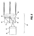
更に、指揮管制センター向けの直視型TFT液晶パネル利用映写機が、特許文献18(名称:複数個のアークランプ及びフライズアイレンズアレイ光ホモジナイザを用い多色光を液晶ディスプレイに送る画像投射システム(Image Projection System With Multiple Arc Lamps and Flyseye Lens Array Light Homogenizer Directing Polychromatic Light on a Liquid Crystal Display);発明者:Clifton et al.)にて提案されている。この映写機は、15インチ対角の色フィルタ付TFT液晶パネルを光変調器として用いており、67インチ対角の画面上に投射することができる。その狙いは、コントラスト比損失なしで画面輝度を向上させることであり、その手段としては、複数個の光源と複数個の反射面を適宜組み合わせて実現した小型高効率光源を使用している。即ち、その照明装置を構成している複数個の光源からの出射光を、風車型に配置した鏡によって互いに結合させることによって、液晶パネルに対しほぼ法線方向(最適コントラスト比方向)から照明光が入射するよう液晶パネルに対する照明光の入射角を抑え、ひいては映写機のコントラスト比を補償膜なしで高めている。また、この文献に記載の映写機では、コントラスト比が更に高まるよう直視型液晶パネルに工夫を施し、従来のパネルで必要であった広視野角膜を廃している。更に、この文献には、直視型液晶パネルに対する照明光入射方向をパネル法線方向からずらし、液晶素材に元々ある光変調特性を活用してコントラスト比を更に高める手法も記載されている。直視型液晶パネルへの入射側で照明光の方向をずらした分は、そのパネルの出射側にフレネルレンズを設けて補償することができる。 Furthermore, a direct-view TFT liquid crystal panel projector for the command and control center is disclosed in Patent Document 18 (name: Image Projection System that sends multiple colors to a liquid crystal display using a plurality of arc lamps and a fly's eye lens array light homogenizer. With Multiple Arc Lamps and Flyseye Lens Array Light Homogenizer Directing Polychromatic Light on a Liquid Crystal Display); Inventor: Clifton et al. This projector uses a TFT liquid crystal panel with a 15-inch diagonal color filter as an optical modulator, and can project onto a 67-inch diagonal screen. The aim is to improve the screen brightness without any loss of contrast ratio. As the means, a small and highly efficient light source realized by appropriately combining a plurality of light sources and a plurality of reflecting surfaces is used. That is, the light emitted from a plurality of light sources constituting the illumination device is coupled to each other by a mirror arranged in a windmill type, so that the illumination light is emitted from a substantially normal direction (optimum contrast ratio direction) to the liquid crystal panel. The incident angle of the illuminating light to the liquid crystal panel is suppressed so that the light is incident, and the contrast ratio of the projector is increased without a compensation film. Further, in the projector described in this document, the direct view type liquid crystal panel is devised so as to further increase the contrast ratio, and the wide viewing cornea necessary for the conventional panel is eliminated. Further, this document also describes a method of further increasing the contrast ratio by shifting the illumination light incident direction with respect to the direct-viewing type liquid crystal panel from the normal direction of the panel and utilizing the light modulation characteristics inherent in the liquid crystal material. The deviation of the direction of the illumination light on the incident side to the direct view type liquid crystal panel can be compensated by providing a Fresnel lens on the exit side of the panel.
しかしながら、このように刮目すべき手だてを採ったにもかかわらず、特許文献18に記載の映写機で達成される効率はまだまだ低水準であり、またコントラスト比は高まったがその輝度は対ディジタル映写機要求輝度に達していない。特に、この文献に記載の映写機では、大型液晶パネルを用いることで大きくなるエタンデュ値を有効利用していない。しかも、その構成部品のなかには画質に悪影響を及ぼしかねないものがある。例えば液晶パネルの前面にある出射光用フレネルレンズは、この文献に記載の通りSXGAレベルの解像度で使用するなら問題ないが、最低でも2048×1080ピクセルの解像度と5000ルーメンの光束が求められる映写機では、顕著なコントラスト比低下や偽像の発生原因になる。使用するアークランプのアークギャップが7mm未満だと、液晶パネルを2インチ対角まで小さくしても高効率が得られない。更に、この文献に記載の単一パネルカラー/白黒映写機ではカラー表示をうまく行えない。例えば普通の吸光性色フィルタアレイを使用すると、高輝度映写機では問題が発生しかねないし、色分解シーケンシャル投射方式を使用すると、動偽像が発生することとなりかねない。加えて、液晶パネルの性能向上が進み、その総コントラスト比も高まっているため、この文献に記載されている手法のうち補償膜を廃してコントラスト比を高める手法や照明光入射方向をずらす手法は、最早その必要性を失っている。 However, in spite of having taken such a measure, the efficiency achieved by the projector described in Patent Document 18 is still at a low level, and the contrast ratio has been increased, but the luminance is required for a digital projector. The brightness has not been reached. In particular, the projector described in this document does not effectively use the etendue value that increases when a large liquid crystal panel is used. In addition, some of its components can adversely affect image quality. For example, the Fresnel lens for outgoing light on the front surface of a liquid crystal panel is not a problem if it is used at a resolution of SXGA level as described in this document, but in a projector that requires a resolution of 2048 × 1080 pixels and a luminous flux of 5000 lumens at a minimum. This causes a significant reduction in contrast ratio and generation of false images. If the arc gap of the arc lamp to be used is less than 7 mm, high efficiency cannot be obtained even if the liquid crystal panel is reduced to 2 inches diagonal. Furthermore, the single panel color / black and white projector described in this document cannot perform color display well. For example, if an ordinary light-absorbing color filter array is used, a problem may occur in a high-intensity projector, and if a color separation sequential projection method is used, a moving false image may be generated. In addition, since the performance of liquid crystal panels has been improved and the total contrast ratio has also increased, among the methods described in this document, there are methods for eliminating the compensation film and increasing the contrast ratio and for shifting the illumination light incident direction. , No longer need that.
このように、画像形成にLCOSデバイスを使用するディジタル映写機が既に何種類か提案されているが、そのために小型LOCSデバイスを使用するのでは、原理上、光束及び効率を十分に高めることができない。他方の直視型TFT液晶パネルは、LCOSデバイスよりエタンデュ値を大きくすることができるのでLCOS液晶利用時に比べ光束を増やせる可能性があるが、これまでに提案されているTFT液晶パネル利用映写機ではまだ不足である。即ち、その効率が期待水準より低く、所要輝度も得られておらず、SMPTEがディジタル映写機認証に際し課すであろうコントラスト比、色むら、色域及び解像度の付加要件も満足していない。 As described above, several types of digital projectors using an LCOS device for image formation have already been proposed. However, if a small LOCS device is used for this purpose, the luminous flux and efficiency cannot be sufficiently increased in principle. The other direct-view TFT liquid crystal panel has a higher etendue value than the LCOS device, so there is a possibility that the luminous flux can be increased compared to when using the LCOS liquid crystal. It is. That is, the efficiency is lower than expected, the required luminance is not obtained, and the additional requirements of contrast ratio, color unevenness, color gamut and resolution that SMPTE will impose upon digital projector authentication are not satisfied.
SMPTEは、現在、ディジタル映写機認証に関する一連の規格を策定中である。その根幹をなす条件は、DCI(Digital Cinema Initiative)と呼ばれる動画スタジオコンソーシアムにて作成されたものである。DCIでは、重要な性能パラメタとして、コントラスト比、ピクセル解像度、画面輝度、ANSI(米国規格協会)コントラスト比、並びに色域及び偽像発生率の許容値を定めている。これらの規格と自由競争市場がディジタル映写機に対し要求しているのは、2000:1オーダのシーケンシャルコントラスト比を色シフトなしで達成すること、大半のスクリーン上に約10000ルーメン以上の光束を提供できること、並びに2048×1080又は4096×2160のピクセル数で表示できることである。 SMPTE is currently developing a series of standards for digital projector authentication. The basic conditions are those created by a video studio consortium called DCI (Digital Cinema Initiative). In DCI, acceptable values for contrast ratio, pixel resolution, screen brightness, ANSI (American National Standards Institute) contrast ratio, color gamut, and false image generation rate are defined as important performance parameters. These standards and the free competition market require digital projectors to achieve a sequential contrast ratio on the order of 2000: 1 without color shift and to provide more than about 10,000 lumens of light on most screens. As well as 2048 × 1080 or 4096 × 2160 pixels.
映画興行事業は、そもそも家庭内映写や普通の事業所内での映写とは異質なものであり、従来からフィルム、フィルム式映写機及び有償配給システムを軸に成り立っていた。有償配給システムとは、様々な映画制作会社から作品の配給を受ける代わりに映画館が券売収入の一部を支払うシステムである。こうした経営が成り立つのは、技術革新が少ないため劇場設備の償却に概ね10〜30年もかけることができ、また故障した機械部品の交換や定期的なランプ交換があるだけで保守点検がほとんど必要ないからである。その損益分岐点は、映写機用ランプのワット数と映画配給元への支払い額との関係で決まる。 In the first place, the movie entertainment business is different from the projection in the home and the ordinary office, and it has traditionally consisted of films, film projectors, and paid distribution systems. A paid distribution system is a system in which a movie theater pays a part of ticket sales revenue instead of receiving distribution of works from various movie production companies. The reason for this management is that because there are few technological innovations, it is possible to spend almost 10 to 30 years to amortize theater equipment, and there is almost no need for maintenance and inspection because of the replacement of defective machine parts and periodic lamp replacement. Because there is no. The break-even point is determined by the relationship between the wattage of the projector lamp and the amount paid to the movie distributor.
ディジタル映写機はこのビジネスモデルを一変させるものであり、その採用にはやや値の張る劇場用設備の導入が必須になる。既存のマイクロディスプレイデバイス利用映写機でディジタル映写を行う場合、高性能だが高価な部品を使用する関係上、フィルム式映写機に比べ3倍ものコスト高になる。更に、昨今のディジタル映写機がどの程度保つかは未知数であるが、ディジタルテレビジョン装置、コンピュータ、通信機器等の電子機器での実績を踏まえると、恐らくは従来のフィルム式映写機より短命で5〜10年程度の寿命になるであろう。既存の電子映写機における技術的陳腐化の進み方や部品故障の生じやすさ、収益上の不安を引き起こしている。従って、ディジタル映写機がフィルム式映写機と肩を並べるものであると早期に認めさせるには、コストメリット、出射光量及び光学的効率の各面で顕著な前進を得る必要があろう。 Digital projectors will change this business model, and it will be necessary to introduce somewhat expensive theater equipment. When digital projection is performed with an existing projector using a micro display device, the cost is three times as high as that of a film projector because of the use of high-performance but expensive components. In addition, the degree to which a recent digital projector is maintained is unknown, but based on the results in electronic equipment such as digital television devices, computers, and communication equipment, it is probably 5 to 10 years shorter than conventional film projectors. It will be about a lifetime. This is causing the technical obsolescence of existing electronic projectors, the likelihood of component failures, and profitability concerns. Therefore, in order to quickly recognize that a digital projector is in line with a film projector, it will be necessary to obtain significant advances in terms of cost merit, emitted light quantity, and optical efficiency.
このように、今求められているのは、ディジタルシネマ水準の性能を有するフルカラー映写機を液晶デバイスの有効活用により実現すること、それも低コストで光学的効率が高く且つ総合的な光スループットがよいものを実現することである。 In this way, what is required now is to realize a full-color projector having a digital cinema level performance by effectively utilizing a liquid crystal device, which is also low in cost, high in optical efficiency and good in overall light throughput. To realize things.
このような要請に応えるため、本発明の一実施形態に係るディジタル映写機は、多色偏光を発生させる照明装置と、その光路上でその多色偏光から略テレセントリックな多色偏光ビームを発生させるレンズ素子と、その多色偏光ビームを複数本のテレセントリックな成分色光ビームに分割する色成分分離器と、それらの成分色光ビームを変調して複数本の変調済成分色光ビームを発生させる複数個の透光性空間光変調器と、それらの変調済成分色光ビームを共通光軸沿いに再結合して変調済多色光ビームを発生させる色成分結合器と、その変調済多色光ビームを表示画面に向ける投射レンズと、を備える。各透光性空間光変調器のエタンデュ値は、照明装置のエタンデュ値に対して15%以内の差に止め、或いは照明装置のエタンデュ値より大きな値にする。 In order to meet such a demand, a digital projector according to an embodiment of the present invention includes an illumination device that generates multi-color polarized light, and a lens that generates a substantially telecentric multi-color polarized beam from the multi-color polarized light on the optical path. An element, a color component separator that divides the multi-color polarization beam into a plurality of telecentric component color light beams, and a plurality of transmission components that modulate the component color light beams to generate a plurality of modulated component color light beams. Optical spatial light modulator, color component combiner for recombining these modulated component color light beams along a common optical axis to generate a modulated multicolor light beam, and directing the modulated multicolor light beam to a display screen A projection lens. The etendue value of each translucent spatial light modulator is kept within 15% of the etendue value of the illuminating device, or is set to a value larger than the etendue value of the illuminating device.
本発明の特徴の一つは、既存の映写機で使用されている小型液晶デバイス例えばLCOSデバイスに代え、より大きなTFT液晶パネルを用いてハイエンド電子映写機を実現できる点にある。 One of the features of the present invention is that a high-end electronic projector can be realized by using a larger TFT liquid crystal panel in place of a small liquid crystal device such as an LCOS device used in an existing projector.
そのため、本発明によれば、5000ルーメン以上の光束を有する投射像を得ることができる。また、様々な種類の光源を使用できる。 Therefore, according to the present invention, it is possible to obtain a projection image having a luminous flux of 5000 lumens or more. Also, various types of light sources can be used.
以下、上述のものもそれ以外のものも含め、いわゆる当業者が理解できるよう詳細に、また本発明の実施形態を示す図面を参照しつつ、本発明の構成及び効果について説明する。 In the following, the configuration and effects of the present invention will be described in detail so as to be understood by those skilled in the art, including the above-mentioned and others, and with reference to the drawings showing embodiments of the present invention.
なお、本発明の構成要件については別紙特許請求の範囲を参照されたい。以下の説明及び別紙図面は、本発明をより好適に理解頂くためのものである。 For the constituent elements of the present invention, refer to the appended claims. The following description and the accompanying drawings are provided for a better understanding of the present invention.
また、本明細書における説明は、本発明に係る装置の構成要素やその装置に密接な関連を有する要素についてのものであり、本明細書で明示説明していない要素についてはいわゆる当業者にとり周知の様々な形態を採りうるのでご理解頂きたい。 In addition, the description in the present specification is about components of the apparatus according to the present invention and elements closely related to the apparatus, and elements not explicitly described in this specification are well known to those skilled in the art. Please understand that it can take various forms.
SMPTEは、現在、ディジタル映写機認証に関する一連の規格を策定中である。その根幹をなす条件は、DCIと呼ばれる動画スタジオコンソーシアムにて作成されたものである。DCIでは、重要な性能パラメタとして、コントラスト比、ピクセル解像度、画面輝度、ANSIコントラスト比、並びに色域及び偽像発生率の許容値を定めている。これらの規格と自由競争市場がディジタル映写機に対し要求しているのは、2000:1オーダのシーケンシャルコントラスト比を色シフトなしで達成すること、大半のスクリーン上で約10000ルーメン以上の光束を提供できること、並びに2048×1080又は4096×2160のピクセル数で表示できることである。 SMPTE is currently developing a series of standards for digital projector authentication. The basic conditions are those created by a video studio consortium called DCI. In DCI, acceptable values for contrast ratio, pixel resolution, screen brightness, ANSI contrast ratio, color gamut, and false image generation rate are defined as important performance parameters. These standards and the free competition market require digital projectors to achieve a sequential contrast ratio on the order of 2000: 1 without color shift and to provide a luminous flux of about 10,000 lumens or more on most screens. As well as 2048 × 1080 or 4096 × 2160 pixels.
本発明では、例えば大型TFT液晶パネルを空間光変調器として用い高輝度ディジタル映写機を構成する。大型TFT液晶パネル以外の大型透光性パネルを用いることもできる。例えばPanorama Labs Inc.が開発しMPC(磁性フォトニック結晶)パネルと呼ばれている磁気光学的偏向スイッチング利用型表示パネル等である。小型LCOSデバイス又は小型透光性液晶パネルを使用する従来のディジタル映写機と異なり、本発明で変調器として使用するのは大型透光性パネル、例えば少なくとも約5インチの対角寸法を有する液晶パネル乃至MPCパネルである。液晶やMPCからなる大型透光性パネルはその面積が広い分多くの光を受光できるので、背景技術の欄で説明したエタンデュ値乃至ラグランジュ不変量原理によれば出射光量も多くなる。また、本発明の実施に必要な光学部品(レンズや鏡)の点数は少なく、それら光路上の光学部品をより緩慢な(光の絞り方が緩い)ものにすることができる。照明光ビームも変調済光ビームもより太くなるので、ダイクロイック面性能を損なうことなしに、また従来の高輝度映写機につきものであった急峻で(光の絞り方がきつくて)複雑な構成の光学系を使用することなしに、輝度を高めることができる。LCOSデバイス等のマイクロディスプレイデバイスを用いた映写機と違い、個々の変調用液晶乃至MPCパネルのエタンデュ値は、照明装置側エタンデュ値に密に整合させることやより大きな値にすることができる。 In the present invention, a high-brightness digital projector is constructed using, for example, a large TFT liquid crystal panel as a spatial light modulator. A large translucent panel other than the large TFT liquid crystal panel can also be used. For example, Panorama Labs Inc. Is a display panel using magneto-optical deflection switching called MPC (Magnetic Photonic Crystal) panel. Unlike conventional digital projectors that use small LCOS devices or small translucent liquid crystal panels, the present invention uses a large translucent panel, such as a liquid crystal panel having a diagonal dimension of at least about 5 inches. MPC panel. Since a large transparent panel made of liquid crystal or MPC can receive a large amount of light due to its large area, the amount of emitted light increases according to the Etendue value or the Lagrange invariant principle described in the background section. In addition, the number of optical components (lenses and mirrors) necessary for the implementation of the present invention is small, and the optical components on the optical path can be made more sluggish (the way of narrowing the light). Because the illumination light beam and the modulated light beam are thicker, the optical structure of the steep (thinning of the light) is complicated without compromising the performance of the dichroic surface and with the conventional high-intensity projector. Luminance can be increased without using a system. Unlike a projector using a micro display device such as an LCOS device, the etendue value of each modulation liquid crystal or MPC panel can be closely matched to the illuminator side etendue value or a larger value.
図2に本発明の一実施形態に係る大画面高輝度投映用映写機50を示す。この映写機50を構成する光学部品の点数は背景技術の欄で説明した従来の映写機と比べ少なく、LCOS型空間光変調器、小型透光性液晶型空間光変調器等のマイクロディスプレイデバイスを使用する従来の映写機に比べその構成はより簡素だがより高い輝度を実現できる。例えば、図1Bに示した特許文献8記載の従来システムのように、マイクロディスプレイデバイスからの光を中間結像させるリレイレンズを用い投射レンズの構成を簡素化する必要も、またその作動距離が長く且つそのFナンバーが小さな光円錐をもたらす投射レンズを用いる必要もないので、投射光学系をより簡素且つ非常に安価なものにすることができる。また、その色成分分離器及び偏光器で高エネルギ且つ広角の光を偏向むらなしに処理するため値の張る特殊ガラスやワイヤグリッド偏光器を用いる必要もない。加えて、従来の映写機では、マイクロディスプレイデバイスや偏光器(の一部)を十分に冷却しないと高エネルギ光を扱えなかったが、それに類する懸念はない。
FIG. 2 shows a
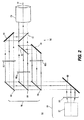
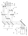
図2に実施形態として示した映写機50は、照明装置28、色成分分離器76、色別変調系90、色成分結合器92及び投射レンズ70を備えている。その照明装置28は、むら補正された偏光を出射する多色光源20と、その偏光をテレセントリック化してテレセントリックな多色偏光ビームを発生させるテレセントリックレンズ62とを備え、その偏光ビームを変調器用ひいては表示用の照明光として出射する。低温鏡52は照明光路を屈曲させ、その光路に沿ってその多色偏光ビームを色成分分離器76に送る。
The
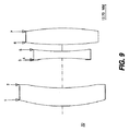
その色成分分離器76は第1ダイクロイック面54を有している。この面54は、テレセントリックな多色偏光ビームをスペクトル分割し、第1波長域成分例えば青色域に属する成分を反射させてテレセントリックな青色光ビームとして第1空間光変調器60bに送る一方、他の成分を透過させて第2ダイクロイック面56に送る。面56はその透過光を更にスペクトル分割し、第2波長域成分例えば緑色域に属する成分を反射させてテレセントリックな赤色光ビームとして第2空間光変調器60gに送る一方、他の成分を透過させて反射面58又はそれに代わるダイクロイック面に送る。面58は第3波長域成分に属するその成分を反射させ第3空間光変調器60rに送る。変調器60b、60g及び60rでは、送られてきたテレセントリックな成分色光ビームを変調し、それによって発生させた変調済成分色光ビームを色成分結合器92に送る。結合器92では、それらの変調済成分色光ビームを、ダイクロイック面68及び72によって共通光軸O沿いに再結合させる。反射面64及び66は、光路を屈曲させて再結合用のダイクロイック面68及び72に向ける面である。再結合によって生じた変調済多色光ビームは共通光軸Oの延長線上にある投射レンズ70に送られる。その投射レンズ70は例えば図8及び図9に示した構造のレンズであり、送られてくる変調済多色光ビームを図示しない表示画面40(図1A、図1B及び図8参照)上に投射する。
The
図3(ブロック図)及び図4(斜視図)に、図2に示した映写機50に適用される寸法関係及び位置関係を示す。図4に示すように、照明光路上に光路屈曲用の反射面102を設けてもよい。
FIG. 3 (block diagram) and FIG. 4 (perspective view) show dimensional relationships and positional relationships applied to the
特記すべきことに、図2〜図4に示した構成の映写機50では、照明装置28内のテレセントリックレンズ62から投射レンズ70へと強い光を導く光路上に光学部品を差し挟む必要がない。空間光変調器60に付随するフレネル視野レンズや、漏洩光を抑えるアパーチャ等を設けてもかまわないが、それ以外にレンズ62・70間光路にレンズ等を追加する必要がないので、その構成が簡素で軽量な高輝度映写機を、従来より低コストで製造することが可能になる。
It should be noted that in the
効率とエタンデュ値の検討
背景技術の欄で述べた通り、従来のLCOS型マイクロディスプレイデバイス利用電子映写機は、その効率が低く10%にも達しないのが普通であった。これはエタンデュ値により記述される幾何光学的条件によるものであり、複数個のランプを用いて照明出力を高め輝度を上げようという試みも出射光増強にはあまり効果がなかった。
Examination of efficiency and etendue value As described in the background section, the conventional electronic projector using the LCOS type micro display device generally has a low efficiency and does not reach 10%. This is due to the geometrical optical conditions described by the etendue value, and attempts to increase the illumination output by using a plurality of lamps to increase the brightness have little effect on the enhancement of the emitted light.
マイクロディスプレイデバイス利用映写機に適用される幾何光学的条件はエタンデュ値についての簡単な計算で検証できる。例えば、その寸法が1.2インチ即ち30.48mm対角、アスペクト比がディジタルシネマフォーマット規格値即ち1.9:1の変調用方形マイクロディスプレイパネルを作成し、それをFナンバー=f/2の光円錐で照明したとする。このパネルのエタンデュ値Eは、非特許文献2に記されている通り、次の式
E=πA/{4(f/#)2} (1)
で計算することができる。この式中、Aはパネルの面積であり、f/#は照明光円錐のFナンバーである。
The geometrical optical conditions applied to a projector using a micro display device can be verified by a simple calculation of the etendue value. For example, a modulation square micro display panel having a dimension of 1.2 inches or 30.48 mm diagonal and an aspect ratio of a digital cinema format standard value or 1.9: 1 is prepared, and the F number = f / 2 is formed. Assume that the light cone is illuminated. As described in
Can be calculated with In this equation, A is the area of the panel, and f / # is the F number of the illumination light cone.
この式に上掲の数値を入れるとエタンデュ値Eは0.12平方インチ・sr即ち75mm2・srになる。これは、映写機内光源から得られるエタンデュ値の上限を表している。実際にはf/2というFナンバーは急峻すぎるので、約f/2.3又はそれより若干急峻な程度の値が実用上の上限であろう。更に、後に例示する通り、光学系の効率を求める際にはNA性損失も考慮しなければならない。NA性損失とは面積Aひいてはエタンデュ値EがNA倍に減ることをいう。マイクロディスプレイデバイスのNAは通常は0.60〜0.90であるので、エタンデュ値Eの計算値が上記の如く75mm2・srなら、NA性損失を勘案した実際の値は、普通はおよそ45〜53mm2・srしかない。 If the above-mentioned numerical value is put into this equation, the etendue value E becomes 0.12 square inches · sr, that is, 75 mm 2 · sr. This represents the upper limit of the etendue value obtained from the light source in the projector. In practice, the F number of f / 2 is too steep, so a practically upper limit would be a value of about f / 2.3 or slightly steep. Furthermore, as will be exemplified later, NA loss must be taken into consideration when determining the efficiency of the optical system. The NA loss means that the area A and hence the etendue value E decreases to NA times. Since the NA of a micro display device is normally 0.60 to 0.90, if the calculated value of the etendue value E is 75 mm 2 · sr as described above, the actual value considering the loss of NA is usually about 45. Only 53mm 2 · sr.
こうしたマイクロディスプレイデバイスを用いたときのスループット効率に対し、より大きな直視型TFT液晶パネル或いはMPCパネルを用いたときのスループット効率が大差を有していることは、空間光変調器対角寸法に対する理論スループット効率の関係をプロットすればわかる。図14のグラフは、空間光変調器対角寸法を約1.3〜20インチの範囲内で切り替えてスループット効率の変化を調べた結果を示している。図中、4本の曲線はそれぞれそのFナンバーがf/2、f/4、f/6又はf/8の光学系についてのものである。前述の通りf/2の光学系はほとんど実用的でなく、むしろf/8未満の緩慢な光学系例えばf/16の光学系の方が実用的である。f/16の光学系についての曲線も、図示例と基本的には同じパターンになる。また、図中の縦破線は5インチ対角を表す線であり、本発明を実施する際にはこの線から右側の領域に属するパネルを変調器として使用する。それは、この寸法未満ではスループット効率が低いため、とりわけ緩慢な光学系では劇的に下がるためである。約5インチ対角以上の最適寸法パネルなら、そのFナンバーがf/8といった緩慢な光学系を用いたときでも70%以上のスループット効率が得られる。 The throughput efficiency when using a larger direct-view TFT liquid crystal panel or MPC panel is significantly different from the throughput efficiency when using such a microdisplay device. This can be seen by plotting the relationship between throughput efficiency. The graph of FIG. 14 shows the result of examining the change in throughput efficiency by switching the diagonal dimension of the spatial light modulator within the range of about 1.3 to 20 inches. In the figure, the four curves are for an optical system whose F number is f / 2, f / 4, f / 6 or f / 8, respectively. As described above, the optical system of f / 2 is hardly practical. Rather, a slow optical system of less than f / 8, for example, an optical system of f / 16 is more practical. The curve for the f / 16 optical system is basically the same pattern as the illustrated example. Also, the vertical broken line in the figure is a line representing a 5-inch diagonal, and a panel belonging to the region on the right side of this line is used as a modulator when implementing the present invention. This is because throughput efficiency is low below this dimension, and so dramatically in slow optics. An optimally sized panel of about 5 inches diagonal or more can achieve a throughput efficiency of 70% or more even when using a slow optical system whose F number is f / 8.
Fナンバーが小さい緩慢な光学系を用いると、ダイクロイック被覆利用光学部品にて入射角依存性の色シフト及びコントラスト比変化が生じるという従来からの問題を、より容易に解決することができる。即ち、複数枚の薄膜からなる積層型ダイクロイック被覆では、光の入射角によってスペクトルエッジが偏倚し、入射角増大につれ普通は約2nm/度の割合で低下する。また、従来から、こうしたダイクロイック被覆を用い偏向性光学部品例えばビームスプリッタを形成することもしばしば行われている。そうした部品ではやはり入射角増大につれコントラスト比が低下していく。これらの問題を比較的容易に解決できるのに加え、場合によっては、Fナンバーをf/8から更に小さくすることで変調器側エタンデュ値(空間光変調器におけるエタンデュ値)を加増すること、即ち照明装置からより多く採光しより明るい画面にすることができる。 When a slow optical system having a small F number is used, the conventional problem that an incident angle-dependent color shift and contrast ratio change occur in an optical component using a dichroic coating can be solved more easily. That is, in the laminated dichroic coating composed of a plurality of thin films, the spectrum edge is deviated depending on the incident angle of light, and usually decreases at a rate of about 2 nm / degree as the incident angle increases. Further, conventionally, a deflectable optical component such as a beam splitter is often formed using such a dichroic coating. In such parts, the contrast ratio decreases as the incident angle increases. In addition to being able to solve these problems relatively easily, in some cases, the F-number is further reduced from f / 8 to increase the modulator side etendue value (the etendue value in the spatial light modulator), that is, More light can be obtained from the lighting device, resulting in a brighter screen.
また、Fナンバーが小さな光学系を用いつつ映写機の効率を高めるには、照明装置側エタンデュ値と変調器側エタンデュ値を整合させること、即ち前者を後者と近い値又は後者より小さな値にすることが望ましい。しかし、マイクロディスプレイデバイスを用いた従来の映写機では、こうしたエタンデュ値整合を実現するとしたら非常に小さな光源が必要になり、ひいては提供可能光量(画面に到達する光束の量)が限られてしまう。これを補うには光源の出射光量を増さねばならず、既存のアークランプを光源として使用するならそのアークギャップ(放電間隙)を拡げねばならない。アークギャップを拡げると照明装置側エタンデュ値も増してしまうので、照明装置側に対する工夫で照明光束を増そうとするとほとんど必然的に、エタンデュ値が過剰化し変調器側エタンデュ値と整合させられなくなる。このように、マイクロディスプレイデバイスを用いる従来型の構成は、エタンデュ値を小さくせざるを得ないため、顕著な不効率、パワーの浪費及び熱の発生を伴う構成となりやすく、ひいてはその熱で小型電気光学部品が損傷を受けやすかった。 In order to increase the efficiency of the projector while using an optical system with a small F number, the illuminator side etendue value and the modulator side etendue value must be matched, that is, the former should be close to the latter or smaller than the latter. Is desirable. However, in a conventional projector using a micro display device, if such etendue value matching is realized, a very small light source is required, and consequently the amount of light that can be provided (the amount of light that reaches the screen) is limited. To compensate for this, the amount of light emitted from the light source must be increased. If an existing arc lamp is used as the light source, the arc gap (discharge gap) must be widened. If the arc gap is widened, the etendue value on the illuminating device side also increases. Therefore, if the illuminating light flux is increased by contrivance to the illuminating device side, the etendue value is excessively increased and cannot be matched with the modulator-side etendue value. As described above, the conventional configuration using the micro display device is inevitably reduced in the etendue value, so that the configuration tends to be accompanied by remarkable inefficiency, waste of power, and generation of heat. The optical components were easily damaged.
これに対し、本発明では、透光性パネル例えば白黒直視型TFT液晶乃至MPCパネルを空間光変調器として用い映写機を構成することができ、ひいては変調器側エタンデュ値を大きくすることができる。従来型の映写機で空間光変調器として使用していた液晶マイクロディスプレイデバイスより数倍も大きいパネルを使用することで、その出射光束を増せるだけでなく、各光学部品に作用するエネルギ密度が下がり、光学系の構成も単純になり、そして色分離/再結合用部品における光学的処理が良質になる。 On the other hand, in the present invention, a projector can be configured by using a translucent panel such as a monochrome direct-view TFT liquid crystal or MPC panel as a spatial light modulator, and the modulator side etendue value can be increased. By using a panel several times larger than the liquid crystal microdisplay device used as a spatial light modulator in a conventional projector, not only the emitted light flux can be increased, but also the energy density acting on each optical component is reduced. In addition, the configuration of the optical system is simplified, and the optical processing in the color separation / recombination component is improved.
また、映写機50ではその高輝度に加え高効率を割合に少数の光学部品で実現している。例えば、その光路上、図3に示した2個所におけるエタンデュ値を互いにほぼ等しくすること、即ち次の関係
照明装置側エタンデュ値=変調器側エタンデュ値
をほぼ成り立たせることで、LCOS型液晶を利用した従来の映写機では到底得られない高効率を実現することができる。
In addition, the
また、変調器側エタンデュ値を更に大きな値にすれば、出射光強度は増さないにしても各光学部品におけるエネルギ密度が下がり、またその解像度の割に空間光変調器内ピクセル寸法も大きくなる。後者のメリットについては後述する。 Further, if the modulator side etendue value is set to a larger value, the energy density in each optical component is lowered even if the emitted light intensity is not increased, and the pixel size in the spatial light modulator is increased for the resolution. . The advantage of the latter will be described later.
図19A〜図19Dに、光源の最適焦点位置における光強度位置及び角度分布計測結果を示す。光源として使用したのは、1.5kW及び2.4kWのCermax(商標;以下表記省略)キセノンアークランプ並びに1.9kWのキセノン管球ランプを複合面リフレクタと併用した光源である。Cermaxキセノンアークランプは米国マサチューセッツ州ウェルズレイ所在のPerkinElmer Inc.から入手できるランプであり、例えば2.4kW品ならそのアークギャップは1.9mm、発光部直径は20mmである。図19Aのグラフに示した強度正規化値対位置データ(焦点位置計測結果)のうち約1/e2ポイント分のデータを使用し、またリフレクタのFナンバーをf/1.3として前掲の式(1)による計算を行うと、照明装置側エタンデュ値E(レンズ62での値)は146mm2・srとなる(光学損失は無視)。 19A to 19D show the light intensity position and angle distribution measurement results at the optimum focal position of the light source. The light sources used were 1.5 kW and 2.4 kW Cermax (trademark; not shown below) xenon arc lamps and 1.9 kW xenon bulb lamps combined with a composite surface reflector. Cermax Xenon Arc Lamp is a product of PerkinElmer Inc., Wellsley, Massachusetts. For example, a 2.4 kW lamp has an arc gap of 1.9 mm and a light emitting portion diameter of 20 mm. Of the intensity normalized value versus position data (focal position measurement result) shown in the graph of FIG. 19A, data for about 1 / e 2 points is used, and the F number of the reflector is f / 1.3. When the calculation according to (1) is performed, the illuminator-side etendue value E (value at the lens 62) is 146 mm 2 · sr (optical loss is ignored).
偏向反転器を使用すれば、この照明装置側エタンデュ値は実質的に倍加し292mm2・srになる。なお、このランプは、そのセラミクス構造を工夫してガス圧を高めたランプであるため、アークギャップが小さい割に定格パワーが高く、市販されてはいるものの平均的なランプとはいい難い。より典型的なランプ、例えば2kWのOsram(登録商標)キセノン管球ランプのアークギャップは5mmである。 If a deflection inverter is used, the illuminator side etendue value is substantially doubled to 292 mm 2 · sr. Since this lamp is a lamp whose gas pressure is increased by devising its ceramic structure, it has a high rated power for a small arc gap and is difficult to call an average lamp although it is commercially available. A more typical lamp, for example a 2 kW Osram® xenon bulb lamp, has an arc gap of 5 mm.
変調用液晶パネルにおけるエタンデュ値即ち変調器側エタンデュ値をこの照明装置側エタンデュ値に近い値又はそれより大きな値にするには、同じく前掲の式(1)を用い変調器側エタンデュ値を求め、変調用液晶パネル例えばTFT液晶パネルの寸法及びFナンバーを、変調器側エタンデュ値が照明装置側エタンデュ値と整合するよう決めればよい。次の表

映写機全体の効率を最高値に近づけるには、このようにして照明装置側エタンデュ値と変調器側エタンデュ値を整合させればよい。但し、変調用液晶パネルや光学系を更に大きくしても映写機の出射光量はさほど変化しない。パネル寸法を大きくすることは可能だが他のシステム要因による制約も加わってくる。従って、光学系を設計する際には、少なくともエタンデュ値に大きな損失が生じないようにしながら、パネルコスト(材料や製造工程で費やされるコスト)と、光路上光学部品コスト(材料や製造工程で費やされるコスト)とのトレードオフを考慮して、パネル寸法を決定するとよい。 In order to bring the overall efficiency of the projector close to the maximum value, the illuminator side etendue value and the modulator side etendue value may be matched in this manner. However, even if the modulation liquid crystal panel and the optical system are further increased, the amount of light emitted from the projector does not change much. Although it is possible to increase the panel size, there are also restrictions due to other system factors. Therefore, when designing an optical system, at least a large loss in the etendue value does not occur, while at the same time panel costs (costs spent in materials and manufacturing processes) and on-path optical component costs (expended in materials and manufacturing processes). Panel size should be determined in consideration of the trade-off with the cost.
LCOSデバイスを利用した従来の液晶マイクロディスプレイデバイス利用高輝度映写機でどの程度のエタンデュ値不整合が生じるか、またその程度が本発明の実施形態に係る高輝度映写機とどの程度違うかについては、例示説明するのが有益であろう。例えば、空間光変調器として1.55インチ対角LCOSデバイス、照明装置として2kW光源2個を使用し、10000ルーメンの光束を呈するディジタル映写機を製造したとする。最小規模の劇場スクリーンなら少なくとも5000ルーメンの光束があればディジタルシネマを好適に映写でき、米国内劇場スクリーンの約80%は10000ルーメンの光束で十分に映写できる。なお、市場には最大で1.7インチ対角寸法、アスペクト比4:3の液晶チップも出回っているが、今のところこれを使用した映写機は市販されていない。 An example of the degree of etendue mismatch caused by a conventional high-intensity projector using a liquid crystal microdisplay device using an LCOS device and how much the degree of the mismatch is different from that of the high-intensity projector according to the embodiment of the present invention is illustrated. It would be useful to explain. For example, assume that a 1.55 inch diagonal LCOS device is used as a spatial light modulator and two 2 kW light sources are used as an illumination device, and a digital projector that produces a 10000 lumen light beam is manufactured. A minimum size theater screen with a luminous flux of at least 5,000 lumens can suitably project a digital cinema, and about 80% of US theater screens can be adequately projected with a luminous flux of 10,000 lumens. In addition, although a maximum of 1.7 inches diagonal dimensions and 4: 3 aspect ratio liquid crystal chips are on the market, no projectors using them are currently available on the market.
このディジタル映写機の変調器側エタンデュ値は、照明用光学系のFナンバーを(比較のため極端に急峻な値である)f/2.3として計算すると95mm2・srになる。また、照明装置側エタンデュ値は、比較のためランプとして前掲のCermaxランプ即ちそのアークギャップが1.9mmのキセノン管球ランプを2個用いるとして計算すると、前掲の通り146mm2・srとなる(ランプ複数化や偏向反転によるエタンデュ値増大は無視)。この場合、照明装置側エタンデュ値・変調器側エタンデュ値間の不整合度は54%になる。照明装置に偏向反転器を設けでもしたらこの値は200%を超える。光源の複数個使用によるエタンデュ値増が加わったら更に大きくなる。 The modulator-side etendue value of this digital projector is 95 mm 2 · sr when the F number of the illumination optical system is calculated as f / 2.3 (which is an extremely steep value for comparison). Further, for the sake of comparison, the Etendue value on the lighting device side is 146 mm 2 · sr as described above when calculated using two Cermax lamps, that is, two xenon bulb lamps having an arc gap of 1.9 mm as lamps. Ignore the etendue increase due to multiples and deflection reversal). In this case, the degree of mismatch between the lighting device side etendue value and the modulator side etendue value is 54%. Even if a deflection inverter is provided in the illumination device, this value exceeds 200%. It becomes even larger if the Etendue value increases due to the use of multiple light sources.
図20A及び図20Bに、キセノン管球ランプ複数個と偏向反転器を用いた映写機にて発生するスポット重複及びエネルギ密度特性曲線重複の例を示す。この構成では、図20Aに示す通りスポット206同士が僅かに重なって現れ、むら補正器より前段で計測した強度曲線208同士も図20Bに示す通り僅かに空間的に重なりあう。
20A and 20B show examples of spot overlap and energy density characteristic curve overlap generated in a projector using a plurality of xenon tube lamps and a deflection inverter. In this configuration, the
不整合度の違いをより深く理解するには、この映写機をまた別の面から見てみるのがよいであろう。そのため、ここでは非特許文献3に記載のデータ、特にその第394頁図6に示されているデータを使用し、そのアークギャップが5mmのランプについて照明装置側エタンデュ値を求めることとする。使用するデータは、アークランプから得られる総パワーとエタンデュ類似パラメタ(センサエタンデュ値=NA×空間光変調器対角寸法DSLM)との関係がアークギャップの変化に応じてどのように変化するかを示すデータである。また、そのランプのエタンデュ値を求めるため、マイクロディスプレイデバイス利用映写機を稼働できるFナンバー値域内の2点を調べることとする。複数通りのFナンバーを調べるのは、そのランプの出力(照明光)が空間的及び方向的に全く均一でなく、実際にはだいぶガウス分布的であるからである。これについては、図19A〜図19Dに示した曲線のうち1.9kWの複合面リフレクタ付ORC(登録商標;以下表記省略)キセノン管球ランプについての曲線を参照されたい。使用するデータ中の総パワー値は、実質的に変調器側エタンデュ値・照明装置側エタンデュ値間不整合度の指標になりうるので、この文献に示されている計測値を利用しセンサエタンデュ値÷システム効率を計算することで、照明装置側エタンデュ値の粗推定値を得ることができる。計算すると、その値は次の値
Fナンバーがf/2.3の場合:
NA・DSLM(mm)=8.56(偏向反転器無)又は4.28(偏向反転器有)
Fナンバーがf/4の場合:
NA・DSLM(mm)=4.92(偏向反転器無)又は2.48(偏向反転器有)
となる。
To better understand the difference in inconsistency, it is a good idea to look at the projector from another perspective. Therefore, here, the data described in
NA · D SLM (mm) = 8.56 (without deflection inverter) or 4.28 (with deflection inverter)
When the F number is f / 4:
NA · D SLM (mm) = 4.92 (without deflection inverter) or 2.48 (with deflection inverter)
It becomes.
他方、同文献の図6に示されている通り、そのアークギャップが5mmのアークランプからのパワー収得率は、Fナンバーがf/2.3で偏向反転器付なら約22%、Fナンバーがf/4で偏向反転器付なら約11%である。前述の通り、照明装置側エタンデュ値の粗推定値を得るには、上掲のセンサエタンデュ値をこのパワー収得率即ちシステム効率で除算すればよい。従って、そのアークギャップが5mmの光源における照明装置側エタンデュ値を計算すると、Fナンバーがf/2.3の場合は94.950/0.22=431.59mm2・sr、Fナンバーがf/4の場合は31.393/0.11=285.39mm2・srとなる。こうして別方法で計算した新たな推定値によれば、高輝度映写機用変調系に対する照明装置のエタンデュ値不整合度は更に高い。また、この推定値は、そのFナンバーとして控えめな値を想定し、複数ランプ併用による顕著なエタンデュ値増大がないとの仮定の下に現用照明装置について求めた推定値である。従って、実際のマイクロディスプレイデバイス利用高輝度ディジタル映写機では、エタンデュ値不整合によって更に顕著な光損失が生じるといえよう。 On the other hand, as shown in FIG. 6 of the same document, the power yield from an arc lamp with an arc gap of 5 mm is about 22% when the F number is f / 2.3 and with a deflection inverter, and the F number is If it is f / 4 and it has a deflection inverter, it is about 11%. As described above, in order to obtain a rough estimated value of the illuminator-side etendue value, the above-mentioned sensor etendue value may be divided by this power acquisition rate, that is, system efficiency. Accordingly, when the etendue value on the lighting device side in a light source having an arc gap of 5 mm is calculated, when the F number is f / 2.3, 94.950 / 0.22 = 431.59 mm 2 · sr, and the F number is f / In the case of 4, it is 31.393 / 0.11 = 285.39 mm 2 · sr. Thus, according to the new estimated value calculated by another method, the etendue value mismatch degree of the illuminating device with respect to the modulation system for a high brightness projector is further higher. Also, this estimated value is an estimated value obtained for the working lighting device under the assumption that a conservative value is assumed as the F number and there is no significant increase in the etendue value due to the combined use of a plurality of lamps. Therefore, it can be said that in an actual high-intensity digital projector using a micro display device, a more remarkable light loss occurs due to etendue value mismatch.
これに対し、本発明の実施形態に係る映写機では変調器側エタンデュ値が照明装置側エタンデュ値に対して整合している。即ち、その変調器側エタンデュ値が、照明装置側エタンデュ値との差が20%以内の値又は照明装置側エタンデュ値を上回る値になっている。これは、従来のマイクロディスプレイデバイス利用映写機にて照明装置側・変調器側間エタンデュ値差がおよそ50%以上もあったのと対照的である。 On the other hand, in the projector according to the embodiment of the present invention, the modulator-side etendue value is matched with the illumination device-side etendue value. That is, the modulator side etendue value is a value within 20% of the difference from the lighting device side etendue value or a value exceeding the lighting device side etendue value. This is in contrast to the fact that the difference between the Etendue value between the illuminating device side and the modulator side is about 50% or more in a conventional projector using a micro display device.
図13に本発明の別の実施形態を示す。この実施形態では、図2と同じ基本的構成を採りつつも、ケースに収めやすくするため部品の向きを変えている。例えば、図示の通り空間光変調器60bの向きを図2における向きから90°回してある。図26に本発明の更に別の実施形態を示す。この実施形態では、3個の直視型TFT液晶空間光変調器及びその後段にある3個の投射レンズを、ディジタルシネマ用映写室に設置しやすい形態で実装してある。
FIG. 13 shows another embodiment of the present invention. In this embodiment, while adopting the same basic configuration as that of FIG. For example, as shown in the figure, the orientation of the spatial
照明用の光源及び光学系
図2〜図4に示した映写機50には光源20に関わる利点もある。まず重要なのは、光源20としてはどのような種類のものを何個用いてもよく、従って市販ランプを光源20として用い低価格化や大量生産を容易に達成できることである。例えば、米国マサチューセッツ州ウェルズレイ所在のPerkinElmer Inc.から入手できるCermaxキセノンアークランプは、高圧ガス封入型であるため従前の管球ランプに比べそのアークギャップが狭く、従って小エタンデュ値システムに対し多量の光を供給できることからマイクロディスプレイデバイス利用映写機で重宝されてきたが、従前のキセノン管球ランプに比べ生産量が少ないため値が張りがちである。これに対して、そのエタンデュ値が大きな大型液晶パネルを使用する図2〜図4に示した構成では、よりもアークギャップが広い従前のキセノン管球ランプでも好適に用いることができ、しかもそのシステム効率を高水準にすることができる。このように市場に広く流通しているランプを使用できることは、大型TFT液晶パネルを使用するメリットの一つである。
The
第2に、キセノン管球ランプのなかには、フィルム式映写機で広く用いられている安上がりな楕円面リフレクタのそれを下回るように、その実効的なエタンデュ値を小さくしたものがある。その仕組みはいろいろあるが、複合面リフレクタを利用するものが比較的多い。例えばゼネラルエレクトリック社製映写機Taleria(商標)で使用されているランプがそれに該当する。これ以外の仕組みとしては、例えば米国ニューヨーク州ボヘミア所在のEELE社で採用している仕組み、即ちアークギャップ自体の方形輪郭を利用して方形スポットを発生させる仕組みがある。これらの仕組みは実効的な照明装置側エタンデュ値を小さくするためのものであり、例えば図19A〜図19Dとして示したグラフで1.5kWのCermaxキセノンアークランプと1.9kWの複合面リフレクタ付ORCキセノン管球ランプを対比した通り、Cermaxキセノンアークランプ並みの値まで照明装置側エタンデュ値を小さくすることができる。しかし、これらの仕組みは、照明装置の複雑化及び高コスト化の原因ともなっている。従って、本発明の実施に当たり採用するなら、例えばEELE社のランプを簡略化したものを光学的結合手段として採用し、コストを最低限に抑え且つ効率を最大限に高めるのが望ましい。具体的には、普通のキセノン管球ランプの側方にリフレクタを配置し、そのリフレクタによって形成される像の幅をパネル幅と略一致させ、更に偏向反転器で像の高さをパネルのアスペクト比に合うよう調整する。また、その後段にはむら補正器例えばレンズレットアレイを配置する。 Secondly, some xenon bulb lamps have an effective etendue value that is smaller than that of cheap elliptical reflectors widely used in film projectors. There are various mechanisms, but there are relatively many that use a compound surface reflector. For example, a lamp used in a general electric projector Taleria (trademark) corresponds to this. As another mechanism, for example, there is a mechanism adopted by EELE, Inc., located in Bohemia, New York, that is, a mechanism for generating a square spot using the rectangular contour of the arc gap itself. These mechanisms are for reducing the effective illuminator side etendue value. For example, in the graphs shown in FIGS. 19A to 19D, a 1.5 kW Cermax xenon arc lamp and a 1.9 kW composite surface reflector ORC are provided. As compared with the xenon bulb lamp, the illuminator-side etendue value can be reduced to the same level as the Cermax xenon arc lamp. However, these mechanisms are also the cause of the complexity and cost of the lighting device. Accordingly, if employed in the practice of the present invention, it is desirable to employ, for example, a simplified EELE lamp as the optical coupling means to minimize costs and maximize efficiency. Specifically, a reflector is arranged on the side of a normal xenon bulb lamp, the width of the image formed by the reflector is made to substantially coincide with the panel width, and the height of the image is adjusted to the aspect of the panel by a deflection inverter. Adjust to match the ratio. Further, a non-uniformity corrector, for example, a lenslet array is arranged at the subsequent stage.
図21A(平面図)に示すように、その照明装置では、例えばアークギャップ182を有する管球ランプ180を、図21B(側面図)に示すように点186を焦点とするリフレクタ184内に収容し、図21Cに示すような像188をなす光をむら補正器に入射させる。偏向反転器を用いているので丸みを帯びた像188が2個でき、それらによって所要アスペクト比を有する方形領域がほぼカバーされるので、光の損失を抑えることができる。
As shown in FIG. 21A (plan view), in the lighting device, for example, a
第3に、複数個のランプを併用する手法も、そのアークギャップが狭いランプでエタンデュ値が小さい照明装置を構成するため用いられてきた。個々のランプで発生する照明光の強度の位置及び角度特性はほぼガウス分布であるので、各照明光の分布ピークが他の照明光の分布裾部分と重なり1個の大きなピークができるよう、ひいては利用できる合計光量が増すよう、それらのランプを複数個設けるという手法である。本発明を実施する際には、この手法を利用できるのみならず、分布裾部分に属する照明光をかなり捉えることができる。ただ、小さなマイクロディスプレイデバイスを所要量の光で照明する際、こうした複雑な構成の光源又はその組合せ以外使用できなかったのとは対照的に、他種光源も使用できる。 Thirdly, a technique using a plurality of lamps has also been used in order to construct a lighting apparatus having a small arc gap and a small etendue value. Since the position and angle characteristics of the intensity of the illumination light generated by each lamp is almost Gaussian, the distribution peak of each illumination light overlaps with the distribution tail of the other illumination light so that one large peak is formed. This is a method of providing a plurality of these lamps so as to increase the total amount of light that can be used. In practicing the present invention, not only can this technique be used, but also illumination light belonging to the distribution tail can be captured considerably. However, when illuminating a small microdisplay device with the required amount of light, other types of light sources can be used, as opposed to those complex light sources or combinations thereof.
第4に、高出力LEDも光源として使用できる。図22A及び図22Bに、そうしたLEDをアレイ化し偏向反転機能を付加した構成を示す。この図のLEDアレイ190は、複数個のLED200をチップ基板198上に並べた構成であり、更に、その除熱のための補助部材例えば放熱器196や、各LED200に対応して設けられた複数個の偏向ビームスプリッタ202からなる偏向ビームスプリッタアレイ192や、前述した偏向反転のための半波長板194を有している。
Fourth, high power LEDs can also be used as light sources. 22A and 22B show a configuration in which such LEDs are arrayed and a deflection inversion function is added. The
図23に、本発明の別の実施形態に係るディジタル映写機を示す。この実施形態は、空間光変調器60r、60g及び60bたる大型液晶パネルを照明するLEDアレイ190r、190g及び190bを、むら補正器22や照明光中継器204と共にRGB各原色用の光路250r、250g及び250b上に設け、各空間光変調器を対応するLEDアレイによって照明する構成である。図22A及び図22Bに示した通り、各LEDアレイは対応する波長域で発光する複数個のLEDを二次元アレイ化したものであり、例えばビームスプリッタ及び半波長板からなる偏向反転部材を有している。各LEDアレイで発生した照明光はレンズレットその他の部材からなるむら補正器22で照度むら補正され、中継器204を介し対応する液晶パネルに入射される。照明される液晶パネルの側も、対応するLEDアレイの発光波長域に感度を有する構成としておくのが望ましい。
FIG. 23 shows a digital projector according to another embodiment of the present invention. In this embodiment, the
その他、超高圧水銀ランプ等も光源として使用できるが、キセノンランプの次代を担う位置にあるのはやはりLEDアレイであろう。それは、複数種類のLEDを組み合わせることで白色光源を形成でき、またその照度むら補正や色分離も容易だからである。更に、Lumiled社のLuxeon(登録商標)シリーズ、Luminus社のPhlatLight(登録商標)シリーズ、Osram社のOstar(登録商標)シリーズといったハイパワーLEDチップでは、近年、その出射パワーが200〜400mW/mm2(色による)のものも現れている。また、LEDは、その発光波長を適宜定めることで、出射光を濾波することなく出射光の色域を所望色域にすることができ、その効率が高い点でも有利である。チップ1個のサイズが約4mm角と大きめで従ってそのエタンデュ値も大きいので、マイクロディスプレイデバイス利用映写機用には適さないが、本発明の実施用には適している。 In addition, an ultra-high pressure mercury lamp or the like can be used as a light source, but the LED array will be the next generation of xenon lamps. This is because a white light source can be formed by combining a plurality of types of LEDs, and the unevenness in illuminance and color separation can be easily performed. Further, high power LED chips such as Lumiled's Luxeon (registered trademark) series, Luminus's PhlatLight (registered trademark) series, and Osram's Ostar (registered trademark) series have recently emitted power of 200 to 400 mW / mm 2. Something (depending on color) also appears. Further, the LED is advantageous in that the emission wavelength can be set to a desired color gamut without filtering the emitted light by appropriately determining the emission wavelength, and the efficiency is high. Since the size of one chip is about 4 mm square and its etendue value is large, it is not suitable for a projector using a micro display device, but is suitable for practicing the present invention.
図5に、テレセントリック多色偏光ビームを発生させる照明装置28の一例構成を示す。この装置28では、まず、光源20で多色無偏光(白色光)を発生させ、それを付随するコリメート系内の放物面鏡又は楕円面鏡によって平行光化(コリメート)し、得られた平行多色無偏光ビームを光源20の出力として広帯域偏光反射器34に入射する。偏光反射器34はその平行多色無偏光ビームをテレセントリックな多色偏光ビーム38に変換する。例えば、光ビーム38即ち照明光ビームとしてp偏光を得たいとする。その場合、偏光反射器34の偏向ビームスプリッタ36としては、光源20からの入射光のうちp偏向成分を透過させs偏向成分を反射させるものを使用する。同じく偏光反射器34内の偏向選択性反射膜44としては、s偏光を半波長板42方向に反射させるものを使用する。半波長板42ではそのs偏光をp偏光に変換する。このp偏光はスプリッタ36を透過したp偏向成分と偏向軸が揃っているので、偏光反射器34から出射される光ビーム38はその偏向状態が整ったビームになる。その後、例えば光の偏向状態を基本的に変化させない手段(図上省略しているレンズレットアレイ等)でその光ビーム38に照度むら補正を施すこともできる。このように、偏向反転を実行することにより、光源20からの出射光をほぼ全て、テレセントリックでその偏向軸が揃いその照度むらもない多色光に変換することができる。また、この処理で発生する光ビーム38の断面は広く、大面積の透光性(液晶)パネルを用いる本発明の実施に好都合である。なお、既存のLCOSデバイス利用映写機でもこれと似た偏向反転方式が用いられているが、それらには生来的に厳しいエタンデュ値制限が課されているので、ここで述べたような出射光量増強効果を全面的に得ることはできない。
FIG. 5 shows an exemplary configuration of the
また、偏向反転器34内偏向ビームスプリッタ36としては、例えば、特許文献19(名称:略偏光ビーム生成用偏光器(Polarizer Apparatus for Producing a Generally Polarized Beam of Light);発明者:Hansen et al.)に記載のワイヤグリッド偏光器を用いることもできる。ワイヤグリッド偏光器には様々な種類があり、それらは例えば米国ユタ州オーレム所在のMoxtek, Inc.から購入することができる。ワイヤグリッド偏光器の際だった利点とは、従前の薄膜型ビームスプリッタと違い強い光を処理でき、また角度に対し割合に不感なことである。図示例でワイヤグリッド偏光器を使用するとしたら、例えばそのワイヤ素子配設面上にあるワイヤ素子が系内光路に面するよう配置するとよい。このようにすると、特許文献20(名称:ディジタル映写機(Digital Cinema Projector);発明者:Kurtz et al.;特許権者:本願出願人)に記載されている熱誘起性複屈折が生じにくくなる。また、いわゆる当業者にはご理解頂ける通り、偏向ビームスプリッタ36を既存のプリズム偏光器、例えばマクニール偏光器にすることもできる。
Further, as the
そして、この偏向反転機能付照明装置には、光源20から得られる照明光をよりむらのない光にして大型TFT液晶パネルに供給するむら補正器12が設けられている。この補正器12は、照度むらのない照明光ビームが空間光変調器に供給されるよう光源20からの出射光を補正する部材であり、例えばインテグレーティングバー、レンズレットアレイ、レンズレットとインテグレーティングコンポーネントの組合せ等の形態で実現するとよい。
The illumination device with a deflection inversion function is provided with an
偏向
空間光変調器に達するまで光の偏向状態が良質に維持されるよう努めることは、1500:1超という高さの所要コントラスト比を実現する上で、重要なことである。照明光の偏向度を高めるための偏光器を追加するとしたら、むら補正器12、偏向反転器、或いはテレセントリックレンズ62の後段がよいであろう。エネルギ密度が高い場合や偏光器に対し角度条件の充足が厳しく要求される場合には、その偏光器として非吸光性偏光器例えばワイヤグリッド偏光器を用い、そのワイヤを空間光変調器側に向けて配置するのが望ましい。エネルギ密度が低く空間的にゆとりがある場合は、価格や入手の容易さを考慮し、吸光色素等の膜を用いた偏光器や、ヨウ素偏光器や、DBEF(登録商標;以下表記省略)膜等の散光反射性偏光膜を初めとするより複雑な構造の偏光器を、用いるのが望ましい。いずれにしても、光学部品に対する照明光の影響に十分注意を払うことが重要である。
Efforts to maintain the light deflection state until reaching the deflection spatial light modulator are important in achieving the required contrast ratio as high as 1500: 1. If a polarizer for increasing the degree of deflection of the illumination light is added, the
また、より綿密に偏向を調整する必要があるときは、テレセントリックレンズ62の後段に更に微調整用の偏光器を配置するのが望ましい。但し、その位置は、液晶パネルから十分に離した方がよい。
Further, when it is necessary to adjust the deflection more closely, it is desirable to further arrange a fine adjustment polarizer at the subsequent stage of the
補償
本発明の利点の一つは、補償器を設ける必要が(ほとんど)ないことである。本件技術分野で周知の通り、膜型の補償器即ち補償膜は数種類ある。そのうち光軸が膜面と平行な一軸膜はAプレート、垂直な一軸膜はCプレートと呼ばれる。その屈折軸が全三次元に亘り相違する二軸膜はOプレートと呼ばれることが多い。また、膜面内でXY複屈折を呈する膜(不等方性媒体から形成されていてXYリターダンスを伴う膜)を以てAプレートと呼び、補償器内ビーム伝搬方向に光軸沿いZ複屈折を呈する膜を以てCプレートと呼ぶこともある。一軸膜の素材には、neがnoより大きい正複屈折素材とneがnoより小さい負複屈折素材とがあるので、A,Cどちらのプレートにもそのne及びnoの値で決まる正負の二種類がある。また、本件技術分野で周知の通り、Cプレートがポリマの一軸圧縮や酢酸セルロースの注型で形成されるのに対し、Aプレートはポリビニルアルコールやポリカーボネート等といったポリマ膜のストレッチングで形成される。本発明の場合、空間光変調器60r、60b及び60gとして大きな液晶パネルを使用するので角度に対する感度を抑えられることができ、従ってCプレート型補償器は(ほとんど)必要なくなる。同様に、その屈折率がX,Y,Zの各方向で異なる二軸膜を使用して所要リターデーションを実現し、ひいては総コントラスト比を高めることもできる。
Compensation One of the advantages of the present invention is that it is not necessary (almost) to provide a compensator. As is well known in the art, there are several types of film compensators or films. Among them, the uniaxial film whose optical axis is parallel to the film surface is called A plate, and the perpendicular uniaxial film is called C plate. Biaxial films whose refractive axes are different in all three dimensions are often called O-plates. In addition, a film exhibiting XY birefringence in the film plane (film formed from an anisotropic medium and accompanied by XY retardance) is called an A plate, and Z birefringence along the optical axis in the beam propagation direction in the compensator The presenting film is sometimes called a C plate. It is made of uniaxial films, n e is because n o greater than positively birefringent materials and n e there is a n o less negative birefringence material, A, C in either plate of the n e and n o There are two types, positive and negative, determined by the value. As is well known in this technical field, the C plate is formed by uniaxial compression of a polymer or casting of cellulose acetate, whereas the A plate is formed by stretching a polymer film such as polyvinyl alcohol or polycarbonate. In the case of the present invention, since large liquid crystal panels are used as the spatial
まず、照明光がほぼ直線偏光である場合は、照明先の液晶層を透過しうるようその偏向軸の向きを合わせる必要がある。液晶層の向きが光路屈曲方向に対し平行又は鉛直になる系構成を採っている場合、例えば各光学部品が上下に並んでいる場合には、Aプレートを用いたほんの僅かな補償だけで精密に、偏向軸の向きを合わせることができる。使用する液晶パネルがTN液晶パネルなら、入射してきた照明光の偏向軸に対して通常は45°、液晶層内で偏向軸が回転するので、半波長板際リターデーションを施しその偏向状態を補正する必要がある。そして、液晶パネル内に達する照明光円錐の頂角が例えば12°以下と小さい場合は、Cプレートを用いた補償が役立つかもしれない。液晶に入射する光の光円錐がそのように尖っていればそうした補償抜きでも高いコントラスト比が得られるけれども、例えばそのコントラスト比が1600:1の画面を有するLG Philips社製液晶ディスプレイのような市販品や、そのコントラスト比が3000:1の画面を有する100インチサイズ液晶ディスプレイパネルのデモ機に倣い、市販の補償器を使用することもできる。 First, when the illumination light is substantially linearly polarized light, it is necessary to align the direction of the deflection axis so that the illumination liquid crystal layer can be transmitted. When the system configuration is such that the orientation of the liquid crystal layer is parallel or perpendicular to the direction of bending of the optical path, for example, when each optical component is lined up and down, it can be precisely adjusted with only a slight compensation using the A plate. The direction of the deflection axis can be adjusted. If the liquid crystal panel to be used is a TN liquid crystal panel, the deflection axis rotates normally 45 ° with respect to the deflection axis of the incident illumination light, so that the deflection state is corrected by applying a half-wave plate retardation. There is a need to. If the vertex angle of the illumination light cone reaching the liquid crystal panel is as small as 12 ° or less, for example, compensation using the C plate may be useful. If the light cone of light incident on the liquid crystal is so sharp, a high contrast ratio can be obtained even without such compensation. For example, a commercially available liquid crystal display such as LG Philips having a screen with a contrast ratio of 1600: 1 is available. A commercially available compensator can also be used in accordance with a demo machine of a 100-inch size liquid crystal display panel having a screen with a contrast ratio of 3000: 1.
光学補償が必要な場合、そのための補償器は、前掲の微調整用偏光器の後段か、液晶パネルの直後且つ偏光検光器よりも前段に、配置するのが望ましい。また、液晶パネルの前後双方に補償器を配置して補償を行うようにしてもよい。 When optical compensation is required, it is desirable that the compensator for the optical compensation be arranged after the fine adjustment polarizer described above or immediately after the liquid crystal panel and before the polarization analyzer. Further, compensation may be performed by arranging compensators on both sides of the liquid crystal panel.
エネルギ密度
マイクロディスプレイデバイスに代えて大きなTFT液晶パネルを用いることは、光路上に配置されている各種光学部品例えば空間光変調器に作用するエネルギ密度との関連で、非常に重要である。マイクロディスプレイデバイスを使用する装置でエネルギ密度が問題になるのは、主に、吸光発熱が多すぎると破壊される部品があるからである。マイクロディスプレイデバイス利用高輝度映写機では、このエネルギ密度問題があるために、高温耐性があるが高価な部品を使用するか、高性能の除熱装置を設ける必要があった。例えば、吸光性薄膜偏光器を用いたのでは高エネルギ光ビームに耐えきれないので、より熱に強いワイヤグリッド偏光器を用いねばならなかった。
The use of a large TFT liquid crystal panel instead of the energy density microdisplay device is very important in relation to the energy density acting on various optical components arranged on the optical path, such as a spatial light modulator. Energy density is a problem in devices that use microdisplay devices, mainly because there are parts that can be destroyed if too much heat is generated. In a high-intensity projector using a micro display device, because of this energy density problem, it is necessary to use high-temperature resistant but expensive parts or to provide a high-performance heat removal device. For example, if a light-absorbing thin film polarizer is used, it cannot withstand a high-energy light beam, so a wire grid polarizer that is more resistant to heat must be used.
これに対し、図2〜図4に示した実施形態等では、その出射光強度をかなり高めた仕様でも、空間光変調器60r、60b及び60gにおけるエネルギ密度が、マイクロディスプレイデバイス利用高輝度映写機におけるそれよりかなり低くなる。例えば1.3インチ対角液晶マイクロディスプレイデバイスを空間光変調器として用いる映写機にて、仮に約10000〜15000ルーメンの光束を出射させたとしたら、その映写機内の空間光変調器や偏光器におけるエネルギ密度がおよそ6W/cm2にも達する。液晶マイクロディスプレイデバイス等の部品が損傷を受けないぎりぎりのエネルギ密度は約15W/cm2であるので、光束を最大限増したとしても約20000ルーメンが限界である。対するに、15インチ対角大型液晶パネルを空間光変調器として用いる映写機では、70000ルーメンに及ぶ多量の光束を出射しているときでも、その映写機内の空間光変調器や偏光器におけるエネルギ密度は約1W/cm2という低さである。このようにエネルギ密度が低いので、安価ではあるが高熱に対する懸念があったためこれまで使用できなかった安価な補助光学部品、例えば吸光性薄膜偏光器を高輝度電子映写機にて使用することが可能になる。これは、より大出力の映写機を実現でき、それによってより大きな画面への投射も可能になるということである。また、本発明に係る映写機及び方法にてその大きなエタンデュ値で低コスト化及び高性能化が達成される理由も、これと同一の又は類似した理由である。
On the other hand, in the embodiment shown in FIGS. 2 to 4 and the like, the energy density in the spatial
関連するエネルギ密度上の問題としては、テレセントリックレンズ62を形成する素材の選び方がある。即ち、その吸光率又は応力複屈折率が低い素材を選択し、熱誘起性複屈折の影響を抑えることが肝要である。例えばアクリルによって形成される高品質フレネルレンズは、通常は高い耐熱性及び透光性を呈するので、十分使用することができる。なかでもアクリルの加圧成型で形成された部品は、その製造プロセスの性質上複屈折率が低くなるので好適に使用できる。或いは、ガラスやより耐久性に優れたポリマ素材、例えば米国ケンタッキー州ルイビル所在のZeon Chemicals社から入手できるZeonex(商標)も、テレセントリックレンズ62の素材として使用することができる。
A related energy density problem is how to select a material for forming the
テレセントリックレンズ
前掲の図2中、テレセントリックレンズ62は照明光を補正しテレセントリックな光に変換するレンズである。テレセントリックレンズとは、そのレンズの実空間(対物空間)、像空間又はその双方における光挙動をテレセントリック化するレンズのことであり、テレセントリック化とは、被写体又は像を過ぎるあらゆる光線(主光線)をコリメートし、その方向を光軸に対し平行にすることをいう。テレセントリックレンズの入射瞳及び出射瞳のうちコリメートされた方の空間にある瞳は無限遠に位置するので、テレセントリックレンズ透過光のうちそちらに抜ける光の角度分布はかなり均一になる。図2に示した実施形態では、像空間のみ(特に液晶パネル近傍)のみで光挙動をテレセントリック化し、出射瞳のみを無限遠に引き離している。本実施形態でこうしたテレセントリック化が重要なのは、照明光路が色別分離されているためもしそれを怠ると色偽像(偽色)が生じかねないからである。また、空間光変調器たる液晶パネルに角度ばらつきがあると、空間光変調器から出射される変調光に別の角度からの変調光が混ざり、表示画面上に色むらが発生するため、これも多液晶パネル映写機では重要である。また、レンズ62として球面レンズを用いてもよいが、図示例では非球面レンズたるフレネルレンズを用いている。更に、フレネルレンズ等のレンズ62でテレセントリック化する構成ではなく、1個又は複数個の反射性素子でテレセントリック化する構成にしてもよい。反射性素子には、横方向色収差やモアレの干渉縞が発生しない、その製造が容易であり例えばプラスチックの成型で大型のものも形成できる、といった利点がある。そして、レンズ62によるテレセントリック化は本映写機を実現する上で確かに重要だが、ダイクロイック膜を有するビームスプリッタ内により細い光ビームを入射できるようにするため、テレセントリック性を若干犠牲にすることもまた有益である。そのようにする場合には、画面上でとるべきサイズに合うよう、ビームエキスパンダを用いその光ビームの太さを適宜調整するとよい。
Telecentric Lens In FIG. 2 described above, the
同図に示した映写機50では、照明装置28からの照明光がテレセントリックレンズ62を経てテレセントリック多色偏光ビームになり色成分分離器76に入射する。その色成分分離器76ではその光ビームを複数個のスペクトル帯域に分割する。フルカラー投映の場合は少なくとも3個のスペクトル帯域、典型的には赤、緑及び青の三帯域に分割する。また、上述のように、その多色含有光ビームの入射角を絞り概ね制限範囲内に収めてあるので、角度ばらつきに起因するスペクトルシフト効果は小さい。
In the
また、本実施形態の映写機50ではテレセントリックレンズ62がかなり大きくなり、通常は空間光変調器60r、60g又は60bの活性領域寸法とほぼ同程度の大きさになる。このようにその直径が大きなレンズ素子を用いる構成には、潜在的な難点として横方向色収差の発生という難点がある。横方向色収差とは、波長の違いで生じる像寸法の微差のことである。図6に、赤色光による像14r、緑色光による像14g及び青色光による像14bの重なり方及びその寸法差を平面的に示す。横方向色収差が生じているため、赤色光像14rは緑色光像14g及び青色光像14bより僅かに大きくなっている。青色光像14bはそれらのなかで最小の寸法である。図15にグラフとして示すように、こうした横方向色収差は、空間光変調器60r、60g乃至60bの対角寸法が大きいほど大きくなる。
Further, in the
横方向色収差を補正するには、例えば照明光路上に収差補正レンズを配置すればよい。例えば、光路のうち1本又は複数本の上にフレネルレンズを付加して横方向色収差を補正するとよい。その場所は、例えばテレセントリックレンズ62のすぐそばでもよいし、その光路に沿ってレンズ62と空間光変調器の間に位置する場所でもよい。
In order to correct the lateral chromatic aberration, for example, an aberration correction lens may be disposed on the illumination optical path. For example, a lateral chromatic aberration may be corrected by adding a Fresnel lens on one or a plurality of optical paths. The location may be, for example, right next to the
横方向色収差を補正するには、或いは、散光性の素子をテレセントリックレンズ62に前置し、補正したい横方向色収差と正負逆だが同じ大きさの横方向色収差を、その素子によってその光路上で発生させるようにしてもよい。通常、レンズ62は中心波長域たる緑色領域で最善の性能を発揮するよう設計されており、他の波長域即ち赤色や青色の領域では横方向色収差が発生するので、その横方向色収差を打ち消せるように散光特性を与えた横方向色収差補正レンズをレンズ62に付加すればよい。
To correct lateral chromatic aberration, or by placing a diffuse element in front of the
いずれの手法を採るにせよ、肝要なのは、個々の光路上にある光学部品の縁だれ(エッジロールオフ)を含め、隣接光路間で照明光の強度及び均質性を最大限に整合させることによって、画面上での色むらで画質が損なわれることがないよう、照明光路を構成することである。 Regardless of which approach is taken, the key is to maximize the intensity and homogeneity of the illumination light between adjacent optical paths, including the edge roll-off of the optical components on the individual optical paths. The illumination optical path is configured so that the image quality is not impaired by the color unevenness on the screen.
そして、一般論としていえば、液晶パネル・投射レンズ間距離即ち変調光路長を色間で等しくすることが望ましい。この点については、先に引用した特許文献12、13等でも述べられている。これに対し、その空間光変調器として大型のTFT液晶パネルを用いる本実施形態の映写機50では、変調光路長ではなく照明光路長を調整している。このように照明光路長の調整で足りるのは、本実施形態の装置が従来の装置ほど照明光の合焦位置に対して敏感でないからである。照明光の合焦位置に対して敏感でないということは、空間光変調器60r、60g及び60bの光軸O沿い位置をテレセントリックレンズ62の焦点にぴったり合わせる必要がなく、互いにずらして調整することができる、ということである。即ち、各空間変調器の光軸O沿い位置を調整することによって、空間光変調器間で変調光路長を精密に整合させることができる。
In general terms, it is desirable to make the distance between the liquid crystal panel and the projection lens, that is, the modulation optical path length equal between colors. This point is also described in
モアレ補償
モアレの干渉縞は、図17に示すフレネルレンズ84を大型液晶パネルのような繰り返し構造と併用するときに生じうる一種の偽像である。その発現を抑えるには、例えば、照明光を十分にデフォーカス(ピンぼけ)にしてフレネルレンズによる像の形成を抑え、強度ビートの発生を防げばよい。また、空間パターン間に周波数ビートが(ほとんど)生じないよう複数個のシリンダレンズを適当な角度差を付けて回転させてもよい。残留する縞は、図25に示すように非常に小さな散乱角を有する散光層146を設けることで、除去することができる。加えて、フレネル視野レンズ84を対応する液晶パネルから引き離すことによっても、モアレの干渉縞を抑え目に付かないようにすることができる。
Moire compensation moire interference fringes are a kind of false image that can occur when the
フレネル視野レンズ84を対応する液晶パネルから引き離す場合、補強として、そのレンズ84に入射するテレセントリック光ビームの径を太くするのが望ましい。このようにすると、レンズ84・液晶パネル間の間隙で光ビームが若干収束しても、その液晶パネル全面がその光で照らされる。これを実現するやり方は少なくとも二通りある。第1のやり方は、テレセントリックレンズ62より後段で色成分分離用のダイクロイック面54等より前段にあるいずこかの場所に、レンズ62を補正する部材を配置し、その部材の出射光ビームの幅が液晶パネルの幅より太くなるようにする、というやり方である。第2のやり方は、ダイクロイック面54等より後段に負特性のレンズを配置し、ダイクロイック面を通過したテレセントリックな光ビームをそのレンズで若干発散させ、太くなった光ビームをフレネル視野レンズ84を介し投射レンズの瞳に送る、というやり方である。
When the
また、図示例では、液晶パネルから見て照明側にフレネル視野レンズ84を配置している。この配置は上述の通り有益であるが、液晶パネルへの入射光がテレセントリックにならないため、例えば約12°の視野をカバーするようCプレートを設ける等して液晶パネルを好適に角度偏向補償しないと、液晶パネルの縁に近い部分でコントラスト比が低下してしまう。従って、空間光変調器たる液晶パネルの前方即ち像側に、フレネル視野レンズ84を移動させるやり方もあり得る。そのやり方を採るには、画質が割合に良好でなければならないので、モアレの干渉縞を何か別の手段で抑える必要がある。更に、これらの方法に加え又は代えて、散光層が吸光性偏光器・レンズ62間に位置することとなるよう散光層付吸光性偏光器をレンズ62・液晶パネル間に配置し、その散光層でモアレを抑えるようにしてもよい。
In the illustrated example, a
空間光変調器60r、60g及び60bの構成
図2〜図4に示した実施形態では、空間光変調器60r、60g及び60bとして透光性TFT液晶パネル、例えば5インチ以上の対角寸法を有するものを用いている。この種の液晶パネルは、例えば2048×1080又は4096×2160ピクセルといった高解像度にすることができるので、ディジタル映写等に好適に使用することができる。また、透光性TFT液晶パネルは従来から直視型パネルとして使用されているが、本実施形態における空間光変調器60r、60g及び60bは投射用であるので、より簡略化した構成のパネルを使用することができる。まず、図7Aに、空間光編著器として使用できる従来の液晶パネル118を示す。このパネル118はディスプレイ向けに製造されたものであり、液晶層120、それに付随する制御電極(薄膜トランジスタ122やITO層124を含む)、並びに色フィルタアレイ132を、ガラス板126とガラス板126の間に挟み込んだ構造を有している。その前後にある偏光膜128は吸光性シートであり、性能が劣化するので高熱が加わらないようにしなければならない。吸光性があるということは、光の吸収によって偏光膜128自体が損傷し、またコントラスト比やスペクトル透過率が低下するにとどまらず、熱の伝搬によって液晶層120の性能にも影響が及び、最終的にはその高熱でコントラスト比及び画質にむらが生じるということである。また、補償膜130はコントラスト比を高める膜であり、通常は、ディスプレイを二次元的に囲み全180°の範囲内のどこから直視しても十分なコントラスト比になるよう構成されているので、これを設けることによって対ディスプレイ視角を拡充することができる。図示は省略しているが、散光層、偏向の再生を支援する層、バックライトユニットから供給される照明光を均す層等、その他の補助膜を有するディスプレイも数多くある。そして、このパネル118と併用されるバックライトユニットとしては、例えば冷陰極蛍光管で発生させた光を内部全反射性光学部品即ち光導波路によって出射する構成のもの、即ち比較的均一な光をパネル118に向けて出射できるものを使用する。
Configuration of
図7Bに、本発明の一実施形態にて液晶空間光変調器60r、60g及び60bとして使用される液晶パネルを示す。この液晶パネルは、光を透過させる領域の縁に沿って配したトランジスタで各ピクセルを形成する多ピクセル構造を採っている。また、トランジスタの保護はブラックマトリクスで行うが、個々のピクセルを色別サブピクセルに分割することもまた色フィルタアレイを設けることも必要ないので、構造的には従来より簡素である。その液晶層120はある程度の剛性を有する2枚の透光性基板(例えばガラス板126)で挟み込まれており、更にその透光性基板の表面は抗反射被覆134及び136となる誘電体で覆われているが、ぎらつき防止処理等の散光処理は施されていない。被覆134及び136は、例えば、当該誘電体を被着させたフィルムベースをその透光性基板に付加して形成する。偏光膜、散光層、視角拡充膜等といった特殊機能膜は不要であり、補償膜130も廃止されている。液晶層120の表面から延ばした法線に対する光の角度偏差が極端に小さいので、補償膜130を設けるにしてもその性能及び費用はかなり抑えうる。また、従来の直視型ディスプレイでは、ユーザが(各方向最大180°の範囲内で)どのような向きで見てもコントラスト比が等しくなるよう、求められることが普通であったが、本実施形態の場合は約2°の視角があれば足りる(15インチ対角の液晶パネルの場合)。空間光変調器60r、60g及び60bの前後にその本体に密接するよう偏光膜128を設ける必要もない。また、前掲の特許文献18等には大型液晶パネルを用いる投射システムが記載されているが、これは低輝度映写機についてのものである。仮に、特許文献18に記載の手法で光束や実効エタンデュ値を増そうとしても、同文献に記載のシステムで使用する色フィルタアレイやサブピクセル別ブラックマトリクスにて問題が生じてしまう。更に、同文献には、液晶パネルに対する光の入射角を小さな角度に保つことでシーケンシャルコントラスト比を高められるよう、偏光器、補償膜、ぎらつき防止層等といった層を取り払う点について記載がある。高輝度映写機で使用する場合、偏光器を分離しておいた方が熱によるむらを防止できて望ましいが、補償膜についてはむしろ、うまく設計して使用した方がコントラスト比向上の面では望ましいであろう。また、同文献では抗反射被覆の必要性が認識されていない。抗反射被覆は、基板からの後方反射によってANSIコントラスト比が低下しチェッカーボード状になる現象、即ちその隣の白色ピクセルの影響で黒色ピクセルのコントラスト比が落ちる現象を防ぐ上で必要である。ディジタル映写機に対しては、200:1以上という高いANSIコントラスト比が求められる。加えて、同文献では、NAの悪影響でスクリーンドア偽像が発生し画質が劣化することも認識されていない。
FIG. 7B shows a liquid crystal panel used as the liquid crystal spatial
また、液晶パネルの近傍にワイヤグリッド偏光器を配置するとよい。この種の偏光器は透過させるべき偏向状態の光以外を反射させるので、強い光を入射してもそのエネルギをほとんど吸収せず、従って映写機50内での強い光の処理に特に適している。使用する偏光器は安価なシート状のもの、例えば特許文献21(発明者:Mi et al.)に記載のものがよい。その前段に微調整用偏光器を配しある程度まで偏向状態を整えることができるので、そのコントラスト比は極端に高くする必要がなく100:1程度でかまわない。また、液晶パネルから見て像側にワイヤグリッド偏光器を設けることで、当該反射光が液晶パネルに戻ることを防ぎ、ひいてはその反射光によるANSIコントラスト比低下を防ぐこともできる。その実施形態は二通りある。一つ目は、ワイヤグリッド偏光器で反射される偏光成分を像の形成に回す形態である。二つ目は、その反射光が空間光変調器たる液晶パネルを迂回しアパーチャ絞りや単純な隔壁部材で阻止されるようワイヤグリッド偏光器を傾ける、という形態である。後者では、偏光器たるプレートの傾きで偏光器透過光が散開するので光学系に収差が発生するが、その収差は細めのワイヤグリッド構造を使用することで抑えられる。また、そのプレートとは逆の角度を採るよう光ビームの光路上にプレートをもう1枚配置することによって、その光ビームの非点収差を直に補正することもできる。その他の収差は、普通はあまり大きくなく補正なしでも画質を確保できる。
A wire grid polarizer may be disposed in the vicinity of the liquid crystal panel. This type of polarizer reflects light other than the deflected light to be transmitted, and therefore absorbs little energy even when strong light is incident, and is therefore particularly suitable for processing strong light in the
更に、液晶層120と偏光器の間に間隔があるので熱が偏光器から液晶層120へと伝搬しにくく、従って像にむらが生じにくい。光が波長域毎に空間分離されているので色フィルタアレイ132も必要ない。色フィルタアレイの廃止は、ディジタル映写機のような高輝度映写機ではひときわ有益なことである。例えば吸光型色フィルタアレイを使用すると、その色フィルタアレイにおける吸光発熱で性能や画質が劣化することがある。反射性型色フィルタアレイは使用できるが、反射光が生じる分損失が増すので、使用する場合は色再現系を設けてシステムレベルで輝度を確保するとよい。更に、色フィルタアレイはその構造の一部としてブラックマスクを備えており、そのブラックマスクはトランジスタ構造に直接光が当たらないようにする役割と、その色フィルタアレイを組成する素材を物理的に保持する役割とを有していた。前者の役割は存置してもよいが後者の役割は最早不要であるので、本実施形態では、ブラックマスクを引き続き使用するか或いは反射性のある被覆等の他種手段を設けることで、トランジスタを入射光から保護するようにしている。そして、各ガラス板126の外向き面上には抗反射被覆134及び136を設けることができる。これらの被覆134及び136は、隣接ピクセルからの漏洩光との相互作用ひいてはチェッカーボード効果の発生を抑え、ANSIコントラスト比を高めるのに有益である。
In addition, since there is a gap between the
そして、液晶パネルから見て像側にその透光性が高い吸光性偏光器を設け、その光路用の偏光検光器として用いるとなおよい。光をこの偏光検光器に通すことでその偏向状態をほぼ直線にすることができ、従って映写機内部品の反射性で多少移相が生じてもその影響を抑えることができる。例えば、図17に示す偏光検光器137はそのエネルギ密度に相応しいワイヤグリッド偏光器等であり、投射レンズの実空間内に且つその偏光検光器137による反射光が空間光変調器に入射しないよう傾けて配置されている。従って、割合に小さな偏光検光器137を用いてコントラスト比を高めることができる。また、この図では偏光検光器137が投射レンズに前置されているが、小型の偏光検光器137であるので投射レンズのアパーチャ絞りの近傍に組み込んでもよい。
Further, it is better to provide an absorptive polarizer having high translucency on the image side when viewed from the liquid crystal panel, and use it as a polarization analyzer for the optical path. By passing the light through the polarization analyzer, the deflection state can be made substantially straight, and therefore the influence can be suppressed even if some phase shift occurs due to the reflectivity of the components in the projector. For example, the
スクリーンドア偽像
直視型液晶デバイスのNAはマイクロディスプレイデバイスのNAに比べ高いので、ピクセル間境界線が画面上に偽像を呈することがある。また、そのデバイスを直視型ディスプレイとして使用するなら問題にならないようなものでも、大きな画面上に画像を拡大表示するとそうした偽像がひときわ目に付くようになる。この偽像は一般にスクリーンドア偽像と呼ばれており、高画質が求められるディジタル映写機では容認できないものである。これを抑えるには、例えば、各動画フレームを投映しているときに、個々のピクセルの減りと、それを囲むピクセル間境界線との境目を、各ピクセルの像を境界線間距離の約1/2に亘り偏倚させることで、ぼかすようにすればよい。人間の目は像を経時平均して捉えるので、このようにして各ピクセルの光エネルギを境界線上にも拡散させると、そのピクセルの像が境界線の全体に亘り拡がって見えるようになる。投映時偏倚分の制御は、その駆動信号の波形やタイミングの調整によって行うことができ、その波形としては例えば正弦波や矩形波を使用できる。この手法はディザリングとして知られており、特許文献22(発明者:Ramanujan;特許権者:本願出願人)に記載の通り、印刷の分野ではしばしば縁をぼかし或いは解像度を高める手段として使用されている。また、ディザリングの実行手法としては、液晶パネルを動かす手法、投射レンズを動かす手法、傾斜型プラノオプティカルプレートやオプティカルウェッジを光路上で回動させる手法等、様々な手法を採用できる。例えば、相直交する二方向から投射レンズの直前にワイヤグリッド偏光器を出し入れし、それによって各ピクセルの上下及び左右境界線双方を均しぼかすようにしてもよい。特に、図27に示す例では、摩擦レス屈曲回動ベアリング139を用い二軸ジンバルマウント上にディザ板138を実装しておき、モータ上のカム、圧電プッシャ、ソレノイド等のディザリングアクチュエータを制御してディザ板138を枢動させることにより、ディザリング動作を実行している。ディザリング動作における枢動範囲は、図示例の場合5°未満でよい。
Since the NA of the screen door pseudo-image direct-view type liquid crystal device is higher than the NA of the micro display device, the boundary line between pixels may present a false image on the screen. Even if the device is not a problem when used as a direct-view display, such a false image becomes noticeable when an image is enlarged on a large screen. This false image is generally called a screen door false image, which is unacceptable for a digital projector that requires high image quality. In order to suppress this, for example, when each moving image frame is projected, the boundary between the reduction of each individual pixel and the boundary line between the pixels surrounding the pixel is displayed. / 2 to make it blurry. Since the human eye perceives the image as an average over time, when the light energy of each pixel is also diffused on the boundary line in this way, the image of the pixel appears to spread over the entire boundary line. Control of deviation during projection can be performed by adjusting the waveform and timing of the drive signal. For example, a sine wave or a rectangular wave can be used as the waveform. This technique is known as dithering and is often used in the field of printing as a means of blurring or increasing the resolution as described in US Pat. Yes. Various methods such as a method of moving a liquid crystal panel, a method of moving a projection lens, and a method of rotating an inclined plano optical plate or an optical wedge on the optical path can be adopted as a dithering execution method. For example, a wire grid polarizer may be put in and out from two directions orthogonal to each other immediately before the projection lens, thereby smoothing both the upper and lower and left and right borders of each pixel. In particular, in the example shown in FIG. 27, a
光学部品を物理的に動かすことなくスクリーンドア偽像の発現を抑えるには、ディジタルカメラ等でよく用いられる偏向ブルアフィルタを用いればよい。スクリーンドア偽像の抑止という点ではデフォーカスが最善だが、デフォーカスさせると隣同士のピクセル間で部分的なエネルギ重複が生じ、エッジシャープネスが損なわれる結果、変調段の伝達関数が幾分劣化してしまう。また、その開口に応じた特定の周波数を遮断するフィルタを設計し、その光路に組み込むというやり方も採れる。 In order to suppress the appearance of the screen door false image without physically moving the optical component, a deflecting buler filter often used in a digital camera or the like may be used. Defocusing is best in terms of suppressing screen door artifacts, but defocusing results in partial energy overlap between adjacent pixels, resulting in a loss of edge sharpness, resulting in some degradation in the transfer function of the modulation stage. End up. In addition, it is possible to design a filter that cuts off a specific frequency according to the aperture and incorporate it in the optical path.
空間光変調器実装手段
図示しないが、3個の空間光変調器60r、60g及び60bは例えば所定の配置枠を有する位置決めアセンブリ内に実装されている。このアセンブリは、各変調器をいずれもほぼ同一面上に正しく位置決めするアセンブリである。このアセンブリを用いると、例えば、変調器60r、60g及び60bにおけるピクセル寸法を通常の直視型液晶パネルにおけるピクセル寸法100〜250μmにした場合でも、それらの変調器60r、60g及び60bを他の光学部品に対して所期通りに位置合わせし、現場で投射レンズの焦点を調整して正しく結像する状態にすることは、機械的には難しくないことである。このように現場可換ユニット化して使用するモジュール方式は、ディジタル映写機では有益なことである。例えば、液晶パネル等のアセンブリ内光学部品が損傷乃至陳腐化したときに、損傷していない又はより高性能の光学部品が組み込まれたアセンブリに交換することができる。マイクロディスプレイデバイス利用型映写機における交換はこれほど容易ではない。
Spatial light modulator mounting means Although not shown, the three spatial
また、そのアセンブリ内の空間光変調器から見て像側、照明側又はその双方に、変調器本体に対し間隔をおいて窓142又は143を設けてあるのは、稼働中に溜まっていく塵埃がそのアセンブリ内に侵入することを阻止するためである。それらの窓142及び143は、偏向乃至補償アセンブリの一部として利用すること、例えば窓自体を偏光器乃至補償器として機能させることや窓板上に偏光膜乃至補償膜を被着させることができるが、いずれにしろ、それらに抗反射被覆147及び148を設けることで後方反射光を阻止し光量損失を抑えることができる。更に、清掃によって寿命を延ばせるよう、それらの面の耐久性は高めてある。そして、図25に示すように、窓板等と液晶パネルとの隙間に通じるよう通気口144を設けてあるので、濾過済の空気をそこから導入して液晶パネルや偏光器を十分に除熱することができる。
In addition, the window 142 or 143 is provided on the image side, the illumination side, or both as viewed from the spatial light modulator in the assembly so as to be spaced from the modulator main body. This is to prevent intrusion into the assembly. These windows 142 and 143 can be used as part of a deflection or compensation assembly, for example, the window itself can function as a polarizer or compensator, or a polarizing film or compensation film can be deposited on the window plate. In any case, however, by providing anti-reflection coatings 147 and 148 on them, it is possible to prevent the back reflected light and to suppress the light amount loss. In addition, the durability of these surfaces is increased so that cleaning can extend their life. As shown in FIG. 25, since the
更に、マイクロディスプレイデバイス利用映写機に比べパネル間隔公差がかなり緩くなる。即ち、マイクロディスプレイデバイス同士の間隔はピクセル寸法×1/2、例えば約5μmの公差で保持しなければならないが、大型液晶パネル同士の間隔は例えば約50〜100μmの公差で保持できればよい。従って、例えば製造時に液晶パネルに付しておいた位置決め基準標識を実装先アセンブリ枠上の対応する目印に対し位置合わせすることや、単純に他の2枚の液晶パネルに対して位置合わせすることで、映写機内の個々の液晶パネルを現場で交換することもできる。特に、その空間光変調器で使用する液晶素材やそのポリイミド製アライメント層が短波長域の光、即ち青色光や紫外光に対し最大の感度を呈する青色光路では、映写機本体他の空間光変調器に対する変調器位置の許容誤差も小さくなるので、このようにそれ1枚を現場で交換できることは重要である。また、図示例の構成において、液晶パネル型空間光変調器30の前に少なくとも偏光器を有する補助パネルを、また当該変調器30の後には少なくとも両面抗反射被覆型偏光器を有する補助パネルを、それぞれ変調器30に対し隙間をおいて配置してもよい。
Furthermore, the panel spacing tolerance is considerably less than that of a projector using a micro display device. That is, the interval between the micro display devices must be maintained with a tolerance of pixel size × 1/2, for example, about 5 μm, but the interval between the large liquid crystal panels only needs to be maintained with a tolerance of, for example, about 50 to 100 μm. Therefore, for example, the positioning reference mark attached to the liquid crystal panel at the time of manufacture is aligned with the corresponding mark on the mounting assembly frame, or simply aligned with the other two liquid crystal panels. Thus, individual LCD panels in the projector can be exchanged on site. Especially in the blue light path where the liquid crystal material used in the spatial light modulator and the alignment layer made of polyimide exhibit the maximum sensitivity to light in the short wavelength range, that is, blue light and ultraviolet light, the spatial light modulator other than the projector main body Since the tolerance of the modulator position with respect to is also reduced, it is important that one can be replaced in this way. Further, in the configuration of the illustrated example, an auxiliary panel having at least a polarizer in front of the liquid crystal panel type
液晶パネル型空間光変調器
まず、先に図14を参照して説明した通り、液晶パネル型空間光変調器60の寸法は、映写機50に対し求められる性能を満たす最適な寸法にすることができる。これは、従来用いられていた小型LCOS液晶利用映写機とは対照的である。具体的には、この映写機50で使用する変調器60のサイズは、通常のラップトップディスプレイより大きなサイズ、例えば約5〜20インチ又はそれ以上の対角寸法にすることができる。また、初期の液晶パネルはまことに応答が遅かったが、地道な改良によって100%以上もの応答速度向上が達成されており、更なる応答速度向上の見込みも立っている。ただ、4msec未満といった優れた応答時間も報告されているとはいえ、ディジタルシネマで要求される水準は高いので、個々のパネルで使用されるあらゆる符号値に対し応答時間をうまくバランスさせ、動偽像の発現を抑えることが肝要である。更に、シャッタリング即ちシャッタを用いたブランキングを実行し、コマの切り替わりの際に遮光するようにするとなおよい。
Liquid Crystal Panel Type Spatial Light Modulator First, as described above with reference to FIG. 14, the size of the liquid crystal panel type
原理的には、液晶パネル型空間光変調器60のサイズは、照明系のエタンデュ値を余すところなく活用できる程度に広く、十分短かな応答時間が得られる程度に狭く、しかもそのピクセル及び電子回路のサイズが通常のTFT液晶パネル製造技術で好適に形成できるサイズになるように決める。また、変調器60のサイズは投射レンズのサイズにも大きく影響するので、投射レンズの製造及び仕組みに関わる要因を十分考慮に入れて検討する。その際重視すべき点の一つは、一般的なピクセル寸法を有する市販の液晶パネルを用いたディジタル映写機で所要の解像度を実現することである。これは、テレビジョン装置やモニタ装置の製造に使用されている大型液晶パネル製造設備を活用するためである。
In principle, the size of the liquid crystal panel type
ここに、従来型TFT液晶パネルのNAは、液晶型マイクロディスプレイデバイスのそれが約90%に達するのに比べ60〜70%程度とかなり低くかった。その一部は駆動用トランジスタ及び接続用導体での遮光による損失であるが、他の一部は図7A中の色フィルタアレイ132に設けられたブラックマトリクスでの遮光による損失である。本発明の各実施形態では、光路が色別に分かれていて液晶パネル毎の色フィルタアレイ132は必要ないので、色フィルタアレイ132を廃止すること、少なくともそのブラックマトリクス中の異色領域間仕切り部分を廃止することができる。その部分のブラックマトリクス、例えば赤色部分と緑色部分を隔てていた部分がない分、図7Bに示すように活性領域が広くてNAが高い。液晶パネルの設計によるが、NAの違いは8〜12%或いはそれ以上に達する。本発明でこうした効果が得られるのは、直視型医用ディスプレイ向け高解像度TFT液晶パネル等多くの白黒液晶パネルと違い、ブラックマトリクスが対ピクセル阻害物にならないようにしているためであるといえる。但し、従来の大型直視型ディスプレイに比べ照明光が強いので、それを遮ってトランジスタ構造を護ることが重要になる。
Here, the NA of the conventional TFT liquid crystal panel was considerably low, about 60 to 70%, compared with that of the liquid crystal type micro display device reaching about 90%. Some of the loss is due to light shielding by the driving transistor and the connecting conductor, and the other part is loss due to light shielding by the black matrix provided in the
また、マイクロディスプレイデバイスに比べてNAが低い分、大型TFT液晶パネルの光量損失は20〜40%程多くなる。この損失を減らすには、ピクセル毎にマイクロレンズを設けて液晶パネル上の透光領域に光を集めればよい。このマイクロレンズアレイは、液晶パネルと別体に設けることも液晶パネル内ガラス板上に設けることもできる。後者の場合は、トランジスタや開口形成層を設ける工程でマイクロレンズアレイを設けることができ、各ピクセルに対するマイクロレンズの位置決めも同じ製造工程で行うことができる。また、液晶パネルから見て像側にもマイクロレンズアレイを設け、開口を形成する仕切りで生じる暗い間隙を埋めることもできる。 In addition, since the NA is lower than that of the micro display device, the light loss of the large TFT liquid crystal panel is increased by about 20 to 40%. In order to reduce this loss, it is only necessary to provide a microlens for each pixel and collect light in a light transmitting region on the liquid crystal panel. This microlens array can be provided separately from the liquid crystal panel or on the glass plate in the liquid crystal panel. In the latter case, the microlens array can be provided in the process of providing the transistor and the opening formation layer, and the positioning of the microlens with respect to each pixel can be performed in the same manufacturing process. In addition, a microlens array can be provided on the image side when viewed from the liquid crystal panel to fill a dark gap generated by a partition that forms an opening.
投射光学系
図8に、図2〜図4に示した実施形態における投射光学系の一例構成を示す。この図に示す例では、その直径がかなり大きなレンズ素子からなる投射レンズ70を用いている。例えば図9中で左端に位置している第1レンズ素子の直径は、変調済成分色光ビームを余さず捉えることができるよう、空間光変調器60r、60g及び60bの対角寸法とほぼ等しく設定されている。このように大きなレンズ素子をガラスで形成することは従来から難しいとされているが、注目すべきことに、これら空間光変調器及びレンズ素子が大きい割にそれらで処理する光は弱く、また要求される光学的表面品質も割合に低水準である。従って、成型等でも容易に製造できる薄いガラス製又はプラスチック製のレンズ素子を用いることができる。更に、フレネルレンズ、回折光学系、勾配屈折率レンズ、反射光学系等も採用に値する。
The projection
図10及び図11に、反射素子を用いた投射光学系の例を示す。この光学系では、空間光変調器60r、60g及び60b(図中60r及び60bを省略)で発生した変調済光ビームをダイクロイック面68及び72によって共通の出射光軸上に集め、その軸上での再結合で発生した変調済多色光ビームを反射素子によって屈曲及び集中させている。このように反射素子を使用すると、前述の通り横方向色収差や軸方向色収差が発現しなくなる反面、図12に示す非対称歪等の他種収差が発現することとなりかねない。そこで、図11に示すように、変調済多色光ビームの光路を第1湾曲反射面78によって屈曲させ、投射レンズ70の合焦面に配置した第2湾曲反射面80に送り、その反射面80によって光路を更に屈曲させる。反射面78は凹面、反射面80は凸面である。反射面78及び80のいずれも非球面でよい。反射面78をトロイダル面にすれば両主軸に沿った歪が更に減る。図12に、上下及び左右方向に亘る視野の歪を、実際の像14aとより理想的な近軸像14pとの対比で示す。なお、反射面としては、ダイクロイック被覆を含む様々な被覆を使用することができる。
10 and 11 show an example of a projection optical system using a reflective element. In this optical system, the modulated light beams generated by the spatial
図10及び図11に例示した投射光学系には、更に偏向に関わる長所もある。即ち、更なる偏向を施したい場合、この光学系ではワイヤグリッド偏光器等の偏光器を1個、追加するだけでよい。色別に投射レンズを設けた場合でも各光路に偏光器を配する必要はない。 The projection optical system illustrated in FIGS. 10 and 11 also has an advantage related to deflection. That is, when it is desired to perform further deflection, it is only necessary to add one polarizer such as a wire grid polarizer in this optical system. Even when a projection lens is provided for each color, it is not necessary to provide a polarizer in each optical path.
光路上への部品追加以外では、例えば色プロファイルの修正が本発明の好適な実施に役立つ。即ち、図2、図3及び図13に示した映写機50では従来と同じく赤、緑及び青の三色で一組としているが、これとは異なる組合せを用いてもよい。例えば赤、緑及び青に加え別の色も含む組合せを用い色域を拡充することや、どれかを別の色に差し替えて投映像に色を付けることができる。いずれの場合も、別の組合せを使用するのに必要な修正を光路上に施せばよい。
Other than the addition of components on the optical path, for example, correction of the color profile is useful for the preferred implementation of the present invention. That is, in the
そして、図1Aに示した従来の映写機10と比べると、図2以降に示した構成の映写機50はかなり高輝度の像を形成することができる。即ち、図1Aに示した映写機10では、その空間光変調器30r、30g及び30bが小型液晶デバイスであるためにラグランジュ不変量及びエネルギ搬送能力が厳しい制約を受けており、提供できる光束が約5000ルーメンから高々25000ルーメンまでの範囲にとどまっていた。これに対し、図2以降に示した映写機50で提供できる光束は多く、30000ルーメンを超え70000ルーメン超の光束を投射することができる。
Compared with the
多投射レンズ実施形態
図17に、本発明の一実施形態に係る映写機50を示す。この映写機は光路毎に投射光学系を分けた構成であり、投射レンズ70r、70g及び70bが順に赤色光、緑色光及び青色光の投射を担っている。また、各光路上には、投射レンズ70r、70g及び70bのうち対応するものに向けてその色の光を収束させるフレネル視野レンズ84が配されている。図18はこの実施形態における光学部品配置を示す斜視図である。この実施形態の利点の一つは、さほど大きなレンズ素子が必要にならないことである。従ってその製造がかなり容易であり、マイクロディスプレイデバイス利用型映写機に比べコスト的にも優れている。また、図示例では投射レンズ70r、70g及び70bを上下に並べて配置しているが、他の並べ方をすること、例えば左右に並べることや同一の円上に並べることも可能である。上下に並べる利点は、画面上でのアスペクト比を単一のアナモルフィックレンズで変えられる点にある。まず、ディジタルシネマでは、画面上でのアスペクト比を1.85から2.39の範囲内で映画毎に設定できる。従って、画面上でのアスペクト比が空間光変調器のアスペクト比と合わないときがある。そうした場合、例えば画面の縁に空白を入れて(レターボクシングして)アスペクト比を合わせればよいが、それでは本来使用できるはずのピクセルが無駄になってしまう。そこで、これを光学的処理で正すため、相直交する二軸間で像の倍率が異なるアナモルフィックレンズを使用する。上述の実施形態で複数個の投射レンズを上下に並べているのは、1個のアナモルフィックレンズアタッチメント)(シリンドリカルレンズ群)で像の幅を伸縮できるようにするためである。
Multi-Projection Lens Embodiment FIG. 17 shows a
また、空間光変調器60を大きくすると、複数個ある投射レンズ同士の間隔も自然に大きくなる。これは、各空間光変調器の光軸が真っ直ぐ映写機外に延びているためである。投射レンズ間隔が大きいと像に視差が生じやすくなる。これを抑えるにはアナモルフィックレンズアタッチメントを複数個使用するか、或いは非常に大きなものを1個使用するか、いずれかが必要になろう。同じ理由で、3個ある投射レンズの焦点を調整し合焦状態を維持するための機構も大きくなる。そこで、本実施形態では、図26に示すように潜望鏡構造152を用い投射レンズ間隔を抑えている。また、この構造152を回動させれば、各液晶パネルからもたらされる像の横位置合わせをその液晶パネル上の像を実際に回動させることなく行うことができる。
Further, when the spatial
更に、偏向反転で光円錐を倍加してあるため各投射レンズに入射する光円錐の左右寸法はその上下寸法の2倍になっている。照明系に発するこうした光円錐を漏れなく捉えうる投射レンズを実現するには、例えば、最も急峻な方向における光円錐の窄まり方に応じてFナンバーを決め、そのFナンバーを呈する回転対称の投射レンズを作成すればよい。この方法は最も単純な方法であるが、作成される投射レンズのその上下寸法が照明光ビームのそれと違うため、その投射レンズは上下方向に沿って部分的に使用されない。 Further, since the light cone is doubled by deflection reversal, the left-right dimension of the light cone incident on each projection lens is twice the vertical dimension. In order to realize a projection lens that can capture such a light cone emitted from an illumination system without omission, for example, an F number is determined according to how the light cone is constricted in the steepest direction, and a rotationally symmetric projection that presents the F number. Create a lens. Although this method is the simplest method, the projection lens is not partially used in the vertical direction because the vertical dimension of the projection lens to be created is different from that of the illumination light beam.
また、より慎重な検討が必要になるが、相直交する二方向でそのFナンバーが異なる投射レンズも作成可能である。例えば、その投射レンズに楕円形のアパーチャ絞りを設ければよい。このように上下方向のFナンバーを抑え窄まり方を緩くする手法は、第1に、上下方向の開口寸法が小さくなるため漏洩光が減りその系のコントラスト比が高まる点で有益であり、第2に、その開口が上下方向に狭い分投射レンズの上下を削れる点で有益である。個々の投射レンズの上下部分を削ることで投射レンズ実装間隔を狭めることが可能になり、ひいては3個ある投射レンズ間の視差を抑えることができる。 Further, although more careful consideration is required, it is possible to create a projection lens having different F-numbers in two orthogonal directions. For example, an elliptical aperture stop may be provided on the projection lens. The technique of suppressing the F number in the vertical direction and relaxing the narrowing in this way is advantageous in that first, the aperture size in the vertical direction is reduced, so that the leakage light is reduced and the contrast ratio of the system is increased. Secondly, it is advantageous in that the upper and lower portions of the projection lens can be cut off because the opening is narrow in the vertical direction. By cutting the upper and lower portions of each projection lens, the projection lens mounting interval can be narrowed, and as a result, the parallax between the three projection lenses can be suppressed.
立体映写
立体映写は3D上映とも呼ばれており、映画上映の分野で多大な関心を獲得している。また、その関心は、劇場へのディジタル映写機の普及が進むにつれて増してきている。そのなかで最も高い画質が得られるシステムは、一方のレンズを透過する偏向状態の光が他方のレンズでは阻止されるよう左右のレンズが構成された眼鏡を看者に装着させ、右目用偏光と左目用偏光を送って右目・左目間に別々の像を届けるものである。この種の立体映写システムでは、通常、左旋偏光と右旋偏光を利用し左右の目に異なる像を送る。それら、偏向状態が異なる二種類の光が相互作用すると有色偽像(偽色)が生じるが、映写機出射光の偏向状態を液晶の作用で全波長に亘り回転させる偏向変換器を設ければ、その有色偽像をより好適に抑えることができる。また、本発明では、大型液晶パネルを空間光変調器として用いているので、その液晶の性質に応じた傾向で既に偏向されている光を変調系から得ることができる。従って、偏向変換器を投射レンズに併設し又は内蔵させ適宜制御することで、右目に適した偏向状態の光と左目に適した偏向状態の光を時分割で発生させることができ、DMD利用型映写機即ち偏向変換を行う前に偏向を施さねばならない映写機に比べ出射光束が多くなる。また、出射光束が少ない既存の映写機ではディジタル3D映写用大型スクリーンを僅かに5フィート・ランベルトにしか照らすことができない。この照度は、既存のディジタルシネマ投射規格即ち14フィート・ランベルトをかなり下回っており、既存の映写機ではこれを達成できないことが明らかである。これに対し、本発明の映写機であれば、大きなエタンデュ値を有する光学系を利用してそうした高い画像形成性能を実現することができる。
3D projection 3D projection is also called 3D screening, and has gained great interest in the field of movie screening. In addition, the interest has increased as digital projectors have spread to theaters. Among them, the system with the highest image quality allows the viewer to wear glasses with left and right lenses so that light in the deflected state that passes through one lens is blocked by the other lens. It sends polarized light for the left eye and delivers separate images between the right and left eyes. This type of stereoscopic projection system usually uses left-handed polarized light and right-handed polarized light to send different images to the left and right eyes. When two types of light with different deflection states interact, a colored false image (false color) is generated, but if a deflection converter is provided that rotates the deflection state of the light emitted from the projector over the entire wavelength by the action of the liquid crystal, The colored false image can be suppressed more suitably. In the present invention, since a large liquid crystal panel is used as a spatial light modulator, light that has already been deflected with a tendency corresponding to the properties of the liquid crystal can be obtained from the modulation system. Therefore, the deflection converter is provided in the projection lens or built in and controlled appropriately, so that light in a deflection state suitable for the right eye and light in a deflection state suitable for the left eye can be generated in a time-sharing manner. The emitted light flux is larger than that of a projector, that is, a projector that must be deflected before deflection conversion is performed. Also, existing projectors that emit a small amount of luminous flux can only illuminate a large digital 3D projection screen with only 5 feet Lambert. This illuminance is well below the existing digital cinema projection standard, 14 feet Lambert, and it is clear that this cannot be achieved with existing projectors. On the other hand, with the projector of the present invention, such high image forming performance can be realized by using an optical system having a large etendue value.
図16に、色別変調系90の像側に偏向変換器82を配置した実施形態を示す。ここで使用する偏向変換器82は例えば米国コネチカット州ボールダ所在のColorlinkから入手できるALPS(商標)シリーズのデバイスであり、図示しないがその後段には微調整用偏光器(検光器)がある。ただ、図示の映写機は投射レンズ70が1個であるので、この偏向変換器82は全可視光域に亘りアクロマティック即ち無彩色なものにしなければならない。それに対し、図17に示す映写機では、3個ある投射レンズに対応して偏向変換器を3個設け、各偏向変換器の偏向軸を右目用・左目用間で切り替える構成を採ることができる。この構成であれば、偏向変換器がアクロマティックでなければならない波長域が単一レンズの場合に比べ狭いため、直線偏向を利用することが可能になり、仕組みがより単純になる。即ち、円偏向利用時には普通は円偏光眼鏡がほぼ必須なのに対し、直線偏向利用時はリターデーション部材抜きの偏光器でよいので、直線偏向の方がコスト的に有利である。
FIG. 16 shows an embodiment in which a deflection converter 82 is arranged on the image side of the color-
図24に、直線偏向を利用し別の形態で立体映写を行う実施形態を示す。本実施形態では、右目向け直線偏光の偏向軸と左目向け直線偏光の偏向軸を互いに直交させ、また液晶パネル群も右目用と左目用で別々にする。即ち、偏向ビームスプリッタ210から出射される二種類の偏向成分のうち一方を第1色別変調系90aに、またそれと直交する方向の偏向成分を第2色別変調系90bに、それぞれ供給する。なお、この図では第2色別変調系90bが枠線のみで描かれているが、その構成は第1色別変調系90aとほぼ同じ構成でよい。前掲の実施形態では偏向軸切替に伴い左右交互に視野が暗くなり右目左目間ちらつきが目に留まる恐れがあるが、本実施形態ではその偏向軸方向が異なる二種類の光をユーザの目に同時に届けるのでそうしたちらつきが生じない。また、一組の液晶パネル群で左右の像を得る構成に比べると、右目用と左目用で液晶パネル群を分けるこの構成では液晶パネル群の駆動速度を1/2に落とすことができ、従って、動偽像の発現を抑えることができる。更に、右目用と左目用の二系統ある色別変調系90a及び90bのうち一方に、偏向状態を回転させることで変調用液晶パネルからの光路長の差を打ち消す半波長板を設けることで、各変調パネル及びその周辺の光学系に入射する光の偏向状態を一致させることができる。例えば、照明光の偏向状態を偏向反転して偏向状態を一状態に揃えるやり方に代え、右目用の大型TFT液晶パネル群に供給される偏光と左目用の大型TFT液晶パネル群に供給される偏光とが、その偏向状態(偏向軸)が互いに直交した偏光になるよう、照明光ビーム中の相直交する偏向成分を両液晶パネル群に配給するやり方を採るとよい。その場合、液晶パネルから見て照明側に半波長板を設けてパネル入射光変調状態を液晶パネル群間で揃える一方、液晶パネルから見て像側に別の半波長板を設けてパネル毎に偏向状態を回転させれば、右目に届く光と左目に届く光の偏向状態が相直交することとなる。
FIG. 24 shows an embodiment in which stereoscopic projection is performed in another form using linear deflection. In the present embodiment, the deflection axis of the linearly polarized light for the right eye and the deflection axis of the linearly polarized light for the left eye are orthogonal to each other, and the liquid crystal panel groups are also separated for the right eye and the left eye. That is, one of the two types of deflection components emitted from the
偏向を利用し右目と左目に別々の情報を届ける方法のほかには、帯域シフトを利用する方法がある。この方法では、例えば、照明装置を右目用と左目用とに分け互いに異なる帯域にて交互に発光させる一方、看者には右目用帯域光を右目に通し左目用帯域光を左目に通す装置を身につけさせておく。或いは、液晶パネル群を右目用と左目用とに分け、照明光の入射先を適宜切り替えるようにする。いずれのやり方でもよいが、右目と左目の間でうまく色バランスを確保しホワイトポイントをほぼ一致させることが重要である。 In addition to the method of using the deflection to deliver different information to the right eye and the left eye, there is a method using a band shift. In this method, for example, the lighting device is divided into a right eye and a left eye and alternately emits light in different bands, while the viewer has a device that passes the right eye band light through the right eye and the left eye band light through the left eye. Let me wear it. Alternatively, the liquid crystal panel group is divided into those for the right eye and those for the left eye, and the incident destination of the illumination light is appropriately switched. Either method can be used, but it is important to ensure a good color balance between the right eye and the left eye so that the white points are substantially matched.
以上説明した通り、図2以降に示した映写機50によれば、大面積のTFT液晶パネルを画像発生用の空間光変調器60r、60g及び60bとして用い、明るい照明装置でそれを照明するようにしたため、総効率を40〜50%程まで高めることができる。図1Aに示した従来のLCOS液晶利用型映写機では、前述の通りこれよりかなり低い効率しか得られないのが普通である。更に、通例によればそのエタンデュ値を大きくすると光学系が複雑且つ高価になってしまうはずであるが、この映写機50では、従来の映写機と違いそうした障りなしに、従来の映写機より高い輝度及び大きなエタンデュ値を実現することができる。
As described above, according to the
また、以上の詳細説明は本発明の好適な実施形態のうちある特定の実施形態に関するものである。ご理解頂ける通り、いわゆる当業者ならば、本発明をこれ以外の形態で実施することや、本発明の技術的範囲を逸脱しないで様々な改良を施すことができる。それら、他の実施形態や改良発明も、別紙特許請求の範囲によって定義される本発明の技術的範囲に属するものとする。例えば、近年では新たな種類のTFTを形成できるようになっている。共役ポリマ、オリゴマ等の素材を使用したOTFT(有機TFT)や、単層内適正拡散させたカーボンナノチューブモノレイヤを有するTFTである。これらのTFTも使用することができる。空間光変調器としては、光変調用液晶デバイスのほか、より最近に開発されたもの、例えばファラデー効果を利用して光を変調するMPCデバイスも使用できる。従って、本発明は、TFT液晶パネルを利用して像を投射する電子映写機に限定されるものではない。 The above detailed description relates to a specific embodiment of the preferred embodiments of the present invention. As will be appreciated, those skilled in the art can implement the present invention in other forms and make various improvements without departing from the technical scope of the present invention. These other embodiments and improved inventions shall belong to the technical scope of the present invention defined by the appended claims. For example, in recent years, new types of TFTs can be formed. These are OTFTs (organic TFTs) using materials such as conjugated polymers and oligomers, and TFTs having carbon nanotube monolayers that have been appropriately diffused within a single layer. These TFTs can also be used. As the spatial light modulator, in addition to a liquid crystal device for light modulation, a more recently developed one such as an MPC device that modulates light using the Faraday effect can be used. Therefore, the present invention is not limited to an electronic projector that projects an image using a TFT liquid crystal panel.
10,50 映写機、12 むら補正器、14a 実際の像、14p 近軸像、14r,14g,14b 赤色(R)、緑色(G)及び青色(B)の像、20 多色光源、20r,20g,20b RGB各色光源、22 むら補正器、22r,22g,22b RGB別むら補正器、24r,24g,24b RGB別偏向ビームスプリッタ、26 ダイクロイック結合器、28 照明装置、28r,28g,28b,82r,82g,82b RGB別レンズ、30r,30g,30b RGB別反射性空間光変調器、32,70 投射レンズ、34 偏光反射器、36,202,210 偏向ビームスプリッタ、38 照明光ビーム、38g,58,64,66,102 反射面、40 表示画面、42,64r,64g,64b,194 半波長板、44 偏向選択性反射膜、52 低温鏡、54,56,68,72 ダイクロイック面(波長選択面)、60r,60g,60b RGB別透光性空間光変調器(変調用液晶パネル)、62 テレセントリックレンズ、70r,70g,70b RGB別投射レンズ、76 色成分分離器、78,80 湾曲反射面、82 偏向変換器、84 フレネル視野レンズ、90,90a,90b 色別変調系、92 色成分結合器、118 変調用液晶パネル、120 液晶層、122 薄膜トランジスタ(TFT)、124 ITO層、126 ガラス板、128 偏光膜、130 補償膜、132 色フィルタアレイ、134,136,147,148 抗反射被覆、137 偏光検光器、138 ディザ板、139 摩擦レス屈曲回動ベアリング、140 媒体駆動回路、141 電源、142,143 窓、146 散光層、150 塵埃阻止シール、152 潜望鏡構造、180 管球ランプ、182 アークギャップ、184 リフレクタ、186 焦点、188 像、190 発光ダイオード(LED)アレイ、190r,190g,190b RGB各色LEDアレイ、192 偏向ビームスプリッタアレイ、196 放熱器、198 チップ基板、200 LED、204 照明光中継器、206 スポット、208 強度曲線、250r,250g,250b RGB各色光路、O 共通光軸、Or,Og,Ob RGB各色光軸。 10,50 Projector, 12 Unevenness corrector, 14a Actual image, 14p Paraxial image, 14r, 14g, 14b Red (R), Green (G) and Blue (B) images, 20 Multicolor light source, 20r, 20g , 20b RGB light source, 22 unevenness corrector, 22r, 22g, 22b RGB unevenness corrector, 24r, 24g, 24b RGB separate beam splitter, 26 dichroic coupler, 28 illuminator, 28r, 28g, 28b, 82r, 82g, 82b RGB separate lens, 30r, 30g, 30b RGB separate reflective spatial light modulator, 32, 70 projection lens, 34 polarization reflector, 36, 202, 210 deflection beam splitter, 38 illumination light beam, 38g, 58, 64, 66, 102 Reflective surface, 40 Display screen, 42, 64r, 64g, 64b, 194 Half-wave plate 44 Deflection selective reflection film, 52 Cryogenic mirror, 54, 56, 68, 72 Dichroic surface (wavelength selection surface), 60r, 60g, 60b Translucent spatial light modulator for RGB (modulation liquid crystal panel), 62 Telecentric lens 70r, 70g, 70b RGB projection lens, 76 color component separator, 78, 80 curved reflecting surface, 82 deflection converter, 84 Fresnel field lens, 90, 90a, 90b color modulation system, 92 color component combiner, 118 liquid crystal panel for modulation, 120 liquid crystal layer, 122 thin film transistor (TFT), 124 ITO layer, 126 glass plate, 128 polarizing film, 130 compensation film, 132 color filter array, 134, 136, 147, 148 anti-reflective coating, 137 polarized light Analyzer, 138 Dither plate, 139 Friction-less bending rotation bearing, 140 medium Body drive circuit, 141 power supply, 142,143 window, 146 diffuse layer, 150 dust prevention seal, 152 periscope structure, 180 bulb lamp, 182 arc gap, 184 reflector, 186 focus, 188 image, 190 light emitting diode (LED) array 190r, 190g, 190b RGB color LED array, 192 deflection beam splitter array, 196 radiator, 198 chip substrate, 200 LED, 204 illumination light repeater, 206 spot, 208 intensity curve, 250r, 250g, 250b RGB color light path, O Common optical axis, Or, Og, Ob RGB color optical axes.
Claims (48)
b)その光路上でその多色偏光から略テレセントリックな多色偏光ビームを発生させるレンズ素子と、
c)その多色偏光ビームを複数本のテレセントリックな成分色光ビームに分割する色成分分離器と、
d)それらの成分色光ビームのうち1本目の光路上に配置されその成分色光ビームを変調して1本目の変調済成分色光ビームを発生させる第1透光性空間光変調器と、
e)上記成分色光ビームのうち2本目の光路上に配置されその成分色光ビームを変調して2本目の変調済成分色光ビームを発生させる第2透光性空間光変調器と、
f)それらの変調済成分色光ビームを表示画面に向ける複数個の投射レンズと、
を備え、第1及び第2透光性空間光変調器それぞれのエタンデュ値を照明装置のエタンデュ値より大きくしたディジタル映写機。 a) an illuminator that generates polychromatic polarization;
b) a lens element that generates a substantially telecentric polychromatic polarization beam from the polychromatic polarization on the optical path;
c) a color component separator that splits the polychromatic polarization beam into a plurality of telecentric component color light beams;
d) a first translucent spatial light modulator disposed on the first optical path of the component color light beams to modulate the component color light beam to generate a first modulated component color light beam;
e) a second translucent spatial light modulator disposed on a second optical path of the component color light beams to modulate the component color light beam to generate a second modulated component color light beam;
f) a plurality of projection lenses that direct the modulated component color light beams to the display screen;
A digital projector in which the etendue value of each of the first and second translucent spatial light modulators is larger than the etendue value of the illumination device.
Applications Claiming Priority (3)
| Application Number | Priority Date | Filing Date | Title |
|---|---|---|---|
| US80881306P | 2006-05-26 | 2006-05-26 | |
| US11/739,775 US20070273797A1 (en) | 2006-05-26 | 2007-04-25 | High efficiency digital cinema projection system with increased etendue |
| PCT/US2007/012124 WO2007139761A2 (en) | 2006-05-26 | 2007-05-22 | Digital cinema projection system with increased etendue |
Publications (2)
| Publication Number | Publication Date |
|---|---|
| JP2009538447A true JP2009538447A (en) | 2009-11-05 |
| JP2009538447A5 JP2009538447A5 (en) | 2010-07-08 |
Family
ID=38694803
Family Applications (1)
| Application Number | Title | Priority Date | Filing Date |
|---|---|---|---|
| JP2009512081A Pending JP2009538447A (en) | 2006-05-26 | 2007-05-22 | Digital projection system with large etendue value |
Country Status (5)
| Country | Link |
|---|---|
| US (1) | US20070273797A1 (en) |
| EP (1) | EP2025151A2 (en) |
| JP (1) | JP2009538447A (en) |
| TW (1) | TW200809260A (en) |
| WO (1) | WO2007139761A2 (en) |
Families Citing this family (26)
| Publication number | Priority date | Publication date | Assignee | Title |
|---|---|---|---|---|
| US20070273798A1 (en) * | 2006-05-26 | 2007-11-29 | Silverstein Barry D | High efficiency digital cinema projection system with increased etendue |
| US7458687B2 (en) * | 2006-05-26 | 2008-12-02 | Eastman Kodak Company | High efficiency digital cinema projection system with increased etendue |
| CN101582445B (en) * | 2008-05-14 | 2012-05-16 | 清华大学 | Thin film transistor |
| CN101599495B (en) * | 2008-06-04 | 2013-01-09 | 清华大学 | Thin-film transistor panel |
| CN101582381B (en) * | 2008-05-14 | 2011-01-26 | 鸿富锦精密工业(深圳)有限公司 | Preparation method of thin film transistor |
| CN101582451A (en) * | 2008-05-16 | 2009-11-18 | 清华大学 | Thin film transistor |
| CN101582447B (en) * | 2008-05-14 | 2010-09-29 | 清华大学 | Thin film transistor |
| CN101587839B (en) * | 2008-05-23 | 2011-12-21 | 清华大学 | Method for producing thin film transistors |
| CN101582449B (en) * | 2008-05-14 | 2011-12-14 | 清华大学 | Thin film transistor |
| CN101582450B (en) * | 2008-05-16 | 2012-03-28 | 清华大学 | Thin film transistor |
| CN101582382B (en) * | 2008-05-14 | 2011-03-23 | 鸿富锦精密工业(深圳)有限公司 | Preparation method of thin film transistor |
| CN101582448B (en) * | 2008-05-14 | 2012-09-19 | 清华大学 | Thin film transistor |
| CN101593699B (en) * | 2008-05-30 | 2010-11-10 | 清华大学 | Method for preparing thin film transistor |
| CN101582446B (en) * | 2008-05-14 | 2011-02-02 | 鸿富锦精密工业(深圳)有限公司 | Thin film transistor |
| CN101582444A (en) * | 2008-05-14 | 2009-11-18 | 清华大学 | Thin film transistor |
| US8237677B2 (en) * | 2008-07-04 | 2012-08-07 | Tsinghua University | Liquid crystal display screen |
| US8390580B2 (en) * | 2008-07-09 | 2013-03-05 | Tsinghua University | Touch panel, liquid crystal display screen using the same, and methods for making the touch panel and the liquid crystal display screen |
| US7926951B2 (en) * | 2008-07-11 | 2011-04-19 | Eastman Kodak Company | Laser illuminated micro-mirror projector |
| JP2010249966A (en) | 2009-04-14 | 2010-11-04 | Hitachi Ltd | Optical engine |
| US8300159B2 (en) * | 2010-04-22 | 2012-10-30 | Cordic Technology Co., Ltd. | Structure of pico projector |
| CN105025279B (en) * | 2014-04-24 | 2017-03-01 | 深圳市绎立锐光科技开发有限公司 | A kind of light-source system and projection display equipment |
| EP3368227B1 (en) | 2015-10-30 | 2021-12-08 | Seurat Technologies, Inc. | Additive manufacturing system and method |
| CN109791347B (en) * | 2016-09-23 | 2022-03-29 | 富士胶片株式会社 | Projection lens and projector |
| JP2018085008A (en) * | 2016-11-25 | 2018-05-31 | 株式会社ジャパンディスプレイ | Image processing apparatus, and image processing method for the same |
| KR102626294B1 (en) | 2017-05-11 | 2024-01-17 | 쇠라 테크널러지스 인코포레이티드 | Switchyard beam routing of patterned light for additive manufacturing |
| CN113938660A (en) * | 2018-03-16 | 2022-01-14 | 深圳光峰科技股份有限公司 | Display device |
Citations (6)
| Publication number | Priority date | Publication date | Assignee | Title |
|---|---|---|---|---|
| JPS62125791A (en) * | 1985-11-26 | 1987-06-08 | Seiko Epson Corp | Projection type color display device |
| JPH0627456A (en) * | 1992-05-15 | 1994-02-04 | Matsushita Electric Ind Co Ltd | Display panel and projective display device using the same |
| JP2002049003A (en) * | 2000-08-02 | 2002-02-15 | Optware:Kk | Magneto-optical effective projector, magneto-optical effective projection method and mirror substrate |
| JP2004333757A (en) * | 2003-05-06 | 2004-11-25 | Seiko Epson Corp | Light source device and projection display apparatus using the same |
| JP2005116684A (en) * | 2003-10-06 | 2005-04-28 | Seiko Epson Corp | Solid light emitting element and projector |
| JP2005250088A (en) * | 2004-03-04 | 2005-09-15 | Mitsubishi Electric Corp | Illuminating device and image display device |
Family Cites Families (45)
| Publication number | Priority date | Publication date | Assignee | Title |
|---|---|---|---|---|
| US3658410A (en) * | 1971-02-08 | 1972-04-25 | Us Navy | Wide angle anamorphic refractive lenses |
| US4864390A (en) * | 1986-08-22 | 1989-09-05 | North American Philips Corporation | Display system with equal path lengths |
| US5758940A (en) * | 1992-03-13 | 1998-06-02 | Hitachi, Ltd. | Liquid crystal Projection display |
| US5903388A (en) * | 1992-06-11 | 1999-05-11 | Sedlmayr Steven R | High efficiency electromagnetic beam projector and systems and method for implementation thereof |
| EP1261213A1 (en) * | 1993-03-16 | 2002-11-27 | Seiko Epson Corporation | Projection-type display apparatus |
| JPH09509759A (en) * | 1994-12-22 | 1997-09-30 | フィリップス エレクトロニクス ネムローゼ フェンノートシャップ | Presentation system with overhead projector |
| US5808795A (en) * | 1995-03-06 | 1998-09-15 | Nikon Corporation | Projection type display apparatus |
| US6062694A (en) * | 1995-03-06 | 2000-05-16 | Nikon Corporation | Projection type display apparatus |
| JPH09159988A (en) * | 1995-12-12 | 1997-06-20 | Nikon Corp | Projection type display device |
| JP3738505B2 (en) * | 1996-05-10 | 2006-01-25 | 株式会社ニコン | Projection display |
| US6111700A (en) * | 1996-09-05 | 2000-08-29 | Fujitsu Limited | Optical display device having a reflection-type polarizer |
| US6010221A (en) * | 1997-05-22 | 2000-01-04 | Nikon Corporation | Projection type display apparatus |
| US6108131A (en) * | 1998-05-14 | 2000-08-22 | Moxtek | Polarizer apparatus for producing a generally polarized beam of light |
| JP3687353B2 (en) * | 1998-06-23 | 2005-08-24 | コニカミノルタオプト株式会社 | Projection optical system |
| US6113239A (en) * | 1998-09-04 | 2000-09-05 | Sharp Laboratories Of America, Inc. | Projection display system for reflective light valves |
| JP2000199883A (en) * | 1998-10-29 | 2000-07-18 | Fujitsu Ltd | Reflection type projector device |
| US6722768B1 (en) * | 1999-10-06 | 2004-04-20 | Seiko Epson Corporation | Projector |
| US6398364B1 (en) * | 1999-10-06 | 2002-06-04 | Optical Coating Laboratory, Inc. | Off-axis image projection display system |
| US6273570B1 (en) * | 1999-10-21 | 2001-08-14 | Clarity Visual Systems, Inc. | Compact light path and package for liquid crystal projection displays |
| US6532044B1 (en) * | 2000-07-21 | 2003-03-11 | Corning Precision Lens, Incorporated | Electronic projector with equal-length color component paths |
| TW496532U (en) * | 2000-10-09 | 2002-07-21 | Prokia Technology Co Ltd | Tri-lens projection display device with equal optical path |
| US6505940B1 (en) * | 2000-10-31 | 2003-01-14 | Eastman Kodak Company | Digital projector |
| CN1201186C (en) * | 2000-12-08 | 2005-05-11 | 索尼株式会社 | Liquid crystal display device and liquid crystal projector device |
| US6567584B2 (en) * | 2001-02-12 | 2003-05-20 | Silicon Light Machines | Illumination system for one-dimensional spatial light modulators employing multiple light sources |
| US6930797B2 (en) * | 2001-02-27 | 2005-08-16 | Eastman Kodak Company | Method and apparatus for printing high resolution images using multiple reflective spatial light modulators |
| US6585378B2 (en) * | 2001-03-20 | 2003-07-01 | Eastman Kodak Company | Digital cinema projector |
| KR20030064371A (en) * | 2001-05-18 | 2003-07-31 | 쓰리엠 이노베이티브 프로퍼티즈 컴파니 | Polarization arrangement |
| US6876481B2 (en) * | 2001-06-13 | 2005-04-05 | Optware Corporation | Spatial light modulator |
| US6808269B2 (en) * | 2002-01-16 | 2004-10-26 | Eastman Kodak Company | Projection apparatus using spatial light modulator |
| US6637888B1 (en) * | 2002-01-24 | 2003-10-28 | Delta Electronics, Inc. | Full color rear screen projection system using a single monochrome TFT LCD panel |
| US6676260B2 (en) * | 2002-04-25 | 2004-01-13 | Eastman Kodak Company | Projection apparatus using spatial light modulator with relay lens and dichroic combiner |
| US6809873B2 (en) * | 2002-09-09 | 2004-10-26 | Eastman Kodak Company | Color illumination system for spatial light modulators using multiple double telecentric relays |
| KR20040024124A (en) * | 2002-09-13 | 2004-03-20 | 삼성전자주식회사 | Color switching projection apparatus with two liquid crystal panel |
| US6831722B2 (en) * | 2002-12-13 | 2004-12-14 | Eastman Kodak Company | Compensation films for LCDs |
| US6758565B1 (en) * | 2003-03-20 | 2004-07-06 | Eastman Kodak Company | Projection apparatus using telecentric optics |
| US6839181B1 (en) * | 2003-06-25 | 2005-01-04 | Eastman Kodak Company | Display apparatus |
| EP1792225A4 (en) * | 2004-09-01 | 2010-07-28 | Optical Res Associates | Compact head mounted display devices with tilted/decentered lens element |
| US7414784B2 (en) * | 2004-09-23 | 2008-08-19 | Rohm And Haas Denmark Finance A/S | Low fill factor wire grid polarizer and method of use |
| US20060158622A1 (en) * | 2005-01-18 | 2006-07-20 | Bhowmik Achintya K | Single walled carbon nanotube doped microdisplay for projection display systems |
| US20060169904A1 (en) * | 2005-01-31 | 2006-08-03 | Grobmyer Joseph E | Active polarization-resolving infrared imager |
| JP2006310737A (en) * | 2005-03-29 | 2006-11-09 | Seiko Epson Corp | Light emitting element, manufacturing method thereof and image display device |
| US7230768B2 (en) * | 2005-04-27 | 2007-06-12 | Christie Digital Systems Inc. | Ultra-bright light engine for projection displays |
| US7198373B2 (en) * | 2005-05-03 | 2007-04-03 | Eastman Kodak Company | Display apparatus using LCD panel |
| US20070024825A1 (en) * | 2005-07-26 | 2007-02-01 | Stephanes Maria De Vaan Adrian | Light valve projection systems with light recycling |
| US7458687B2 (en) * | 2006-05-26 | 2008-12-02 | Eastman Kodak Company | High efficiency digital cinema projection system with increased etendue |
-
2007
- 2007-04-25 US US11/739,775 patent/US20070273797A1/en not_active Abandoned
- 2007-05-22 WO PCT/US2007/012124 patent/WO2007139761A2/en active Application Filing
- 2007-05-22 EP EP07795147A patent/EP2025151A2/en not_active Withdrawn
- 2007-05-22 JP JP2009512081A patent/JP2009538447A/en active Pending
- 2007-05-25 TW TW096118649A patent/TW200809260A/en unknown
Patent Citations (6)
| Publication number | Priority date | Publication date | Assignee | Title |
|---|---|---|---|---|
| JPS62125791A (en) * | 1985-11-26 | 1987-06-08 | Seiko Epson Corp | Projection type color display device |
| JPH0627456A (en) * | 1992-05-15 | 1994-02-04 | Matsushita Electric Ind Co Ltd | Display panel and projective display device using the same |
| JP2002049003A (en) * | 2000-08-02 | 2002-02-15 | Optware:Kk | Magneto-optical effective projector, magneto-optical effective projection method and mirror substrate |
| JP2004333757A (en) * | 2003-05-06 | 2004-11-25 | Seiko Epson Corp | Light source device and projection display apparatus using the same |
| JP2005116684A (en) * | 2003-10-06 | 2005-04-28 | Seiko Epson Corp | Solid light emitting element and projector |
| JP2005250088A (en) * | 2004-03-04 | 2005-09-15 | Mitsubishi Electric Corp | Illuminating device and image display device |
Also Published As
| Publication number | Publication date |
|---|---|
| EP2025151A2 (en) | 2009-02-18 |
| WO2007139761A3 (en) | 2008-02-14 |
| US20070273797A1 (en) | 2007-11-29 |
| TW200809260A (en) | 2008-02-16 |
| WO2007139761A2 (en) | 2007-12-06 |
Similar Documents
| Publication | Publication Date | Title |
|---|---|---|
| JP2009538449A (en) | Digital projection system with large etendue value | |
| JP2009538448A (en) | Digital projection system with large etendue value | |
| JP2009538447A (en) | Digital projection system with large etendue value | |
| CN100376923C (en) | Display apparatus | |
| US7188953B2 (en) | Display apparatus using LCD panel | |
| US7559653B2 (en) | Stereoscopic display apparatus using LCD panel | |
| US7575327B2 (en) | Image display apparatus | |
| US7198373B2 (en) | Display apparatus using LCD panel | |
| JP3057232B2 (en) | Two-panel LCD projector | |
| US7334897B2 (en) | Display apparatus using LCD Panel | |
| CN1453606A (en) | Projector using space light modulator with relay lens and dichroic combiner | |
| CN101455078A (en) | Digital cinema projection system with increased etendue | |
| JP2006011298A (en) | Liquid crystal projector system | |
| JP2006145644A (en) | Polarization splitter and projection display apparatus using the same | |
| US6736515B2 (en) | Image display device | |
| JP2004070095A (en) | Optical waveguide, optical unit, and video display unit using same | |
| US7559654B1 (en) | High luminance display apparatus using LCD panel | |
| JP2007206141A (en) | Projector | |
| JP4487484B2 (en) | LIGHTING DEVICE AND PROJECTOR HAVING THE SAME | |
| JP4283569B2 (en) | Single-panel LCD projector | |
| JP2008089632A (en) | Projector | |
| JP2004264663A (en) | Reflective liquid crystal projector | |
| JP2008083533A (en) | Position adjusting method for first light modulating element and second light modulating element for image display apparatus |
Legal Events
| Date | Code | Title | Description |
|---|---|---|---|
| A521 | Request for written amendment filed |
Free format text: JAPANESE INTERMEDIATE CODE: A523 Effective date: 20100518 |
|
| A621 | Written request for application examination |
Free format text: JAPANESE INTERMEDIATE CODE: A621 Effective date: 20100518 |
|
| A521 | Request for written amendment filed |
Free format text: JAPANESE INTERMEDIATE CODE: A523 Effective date: 20110518 |
|
| A977 | Report on retrieval |
Free format text: JAPANESE INTERMEDIATE CODE: A971007 Effective date: 20120418 |
|
| A131 | Notification of reasons for refusal |
Free format text: JAPANESE INTERMEDIATE CODE: A131 Effective date: 20120807 |
|
| A02 | Decision of refusal |
Free format text: JAPANESE INTERMEDIATE CODE: A02 Effective date: 20130108 |