JP2012177521A - Outside air intake air conditioning system - Google Patents
Outside air intake air conditioning system Download PDFInfo
- Publication number
- JP2012177521A JP2012177521A JP2011040798A JP2011040798A JP2012177521A JP 2012177521 A JP2012177521 A JP 2012177521A JP 2011040798 A JP2011040798 A JP 2011040798A JP 2011040798 A JP2011040798 A JP 2011040798A JP 2012177521 A JP2012177521 A JP 2012177521A
- Authority
- JP
- Japan
- Prior art keywords
- air
- outside air
- return
- outside
- intake
- Prior art date
- Legal status (The legal status is an assumption and is not a legal conclusion. Google has not performed a legal analysis and makes no representation as to the accuracy of the status listed.)
- Granted
Links
Images


Landscapes
- Central Air Conditioning (AREA)
Abstract
Description
本発明は、外気冷熱を利用した外気取入空調システムに関する。 The present invention relates to an outside air intake air conditioning system using outside air cooling heat.
従来、データセンタのIT機器室等では、空調機からの冷気を例えば床下からサーバが収納されたラックに送風し、ラックで温められて天井付近へ上昇した空気を空調機に還気してIT機器室内の温湿度環境を調整している。 Conventionally, in an IT equipment room of a data center, for example, cool air from an air conditioner is blown from a floor to a rack in which a server is stored, and air heated by the rack and raised to the vicinity of the ceiling is returned to the air conditioner. The temperature and humidity environment in the equipment room is adjusted.
なお、CPUの処理能力の向上や、ブレードサーバーの普及等に伴って、IT機器室内の機器の発熱量が増加し、これを冷却するのに必要な冷却空気量が急激に増加しており、IT機器室内の機器を冷却するために多大なエネルギーを必要としていた。 With the improvement of CPU processing capacity and the spread of blade servers, etc., the amount of heat generated in the equipment in the IT equipment room has increased, and the amount of cooling air required to cool it has increased rapidly. A lot of energy was required to cool the equipment in the IT equipment room.
このため、冬期等の低温外気を取り入れて外気冷房を行うことで、IT機器室内の機器を冷却するためのエネルギーを抑制することも行われている。 For this reason, the energy for cooling the apparatus in IT equipment room is also suppressed by taking in the low temperature outside air of winter etc. and performing outside air cooling.
外気冷房を行う場合、IT機器室への給気を全て屋外から取り入れた外気とする全外気運転の他、外気空気と還気空気とを混合してIT機器室に供給する混気運転を行うが、外気空気と還気空気とが十分に混合されないままIT機器室内に供給すると、温度分布が生じ、室内温度のバラツキが生じる。 When performing outside air cooling, in addition to all outside air operation in which all the air supplied to the IT equipment room is taken from the outside, mixed air operation is performed in which outside air and return air are mixed and supplied to the IT equipment room. However, if the outside air and the return air are supplied to the IT equipment room without being sufficiently mixed, a temperature distribution occurs and the room temperature varies.
特に、IT機器室の空調システムのように、外気と還気との温度差が大きい場合、前記室内温度のバラツキが顕著となる。 In particular, when the temperature difference between the outside air and the return air is large as in the air conditioning system of the IT equipment room, the variation in the room temperature becomes significant.
このため、取り入れる外気量を制限して室内温度のバラツキが大きくならない範囲で運用することになり、外気冷房による省エネ効果が減少するという問題点があった。 For this reason, the amount of outside air to be taken in is limited to operate in a range in which the variation in room temperature does not increase, and there is a problem that the energy saving effect due to the outside air cooling is reduced.
また、温度差が大きい外気空気と還気空気とを均質に混合させるために、床下チャンバやリターンダクト等の流路を長くとり、複数の気流変換部を配置することも考えられるが、システム構成の複雑化や大型化を招くといった問題点があった。 In addition, in order to uniformly mix outside air and return air having a large temperature difference, it is conceivable that a long flow path such as an underfloor chamber or a return duct is provided and a plurality of airflow conversion units are arranged. There has been a problem in that it causes complexity and enlargement.
そこで、本発明は、上記の問題に鑑み、限られた空間内で効果的に外気空気と還気空気とを混合する技術の提供を課題とする。 Then, this invention makes it a subject to provide the technique which mixes external air and return air effectively in the limited space in view of said problem.
上記課題を解決するため、本発明の外気取入空調システムは、
空調空間への送風を行う送風機と、
送風機の上流側に設けた給気チャンバと、
前記給気チャンバに屋外から外気を取り入れて所定の外気流入方向へ流入させる外気取入部と、
前記空調空間からの還気を前記給気チャンバへ前記外気と交差する方向で流入させる還流部と、
前記外気を前記外気流入方向に透過させて、当該外気中の夾雑物を捕集するフィルタと、
を備え、
前記フィルタの外気流入方向下流側の面に、前記還気の流入方向に長手の溝部を設け、当該溝部が、前記還気の流入方向と直交する断面において前記外気流入方向上流側に向けてその幅が収束する(減少する)形状(凹形状)である。
In order to solve the above problems, the outside air intake air conditioning system of the present invention is:
A blower that blows air to the air-conditioned space;
An air supply chamber provided upstream of the blower;
An outside air intake section for taking outside air into the air supply chamber from the outside and allowing it to flow in a predetermined outside air inflow direction;
A recirculation unit for allowing return air from the air-conditioned space to flow into the air supply chamber in a direction crossing the outside air;
A filter that permeates the outside air in the direction of inflow of the outside air and collects contaminants in the outside air; and
With
A longitudinal groove in the return air inflow direction is provided on the downstream surface of the filter in the outside air inflow direction, and the groove is oriented toward the upstream side in the outside air inflow in a cross section orthogonal to the inflow direction of the return air. The shape converges (decreases) in width (concave shape).
前記外気取入空調システムは、前記フィルタの溝部を前記外気と前記還気の交差する位置の下流に配置し、前記溝部内を通る還気と前記フィルタを透過した外気とが混合する空気を前記送風機で前記空調空間に送風しても良い。 In the outside air intake air conditioning system, the groove portion of the filter is arranged downstream of the position where the outside air and the return air intersect, and the air mixed with the return air passing through the groove portion and the outside air that has passed through the filter is mixed with the air. The air-conditioned space may be blown with a blower.
前記外気取入空調システムは、前記フィルタの還気流入方向上流側の端面に、当該フィルタ内側(ろ材からみて外気取入口側)へ前記還気が流入するのを遮る遮蔽部材を設けても良い。 In the outside air intake air conditioning system, a shielding member may be provided on the upstream end face of the filter in the return air inflow direction to block the return air from flowing into the filter inside (the outside air intake side as viewed from the filter medium). .
前記外気取入空調システムは、前記空調空間を経た空気を還気として前記還流部に導く還気流路と、
前記還気を屋外へ排出する排出部と、
前記外気取入部及び前記還流部にそれぞれ設けたダンパの開閉を制御して運転状態を選択的に制御する制御部と、を備え、
前記制御部が、外気の状態に応じて、
前記外気取入部のダンパを開、前記還流部のダンパを閉とし、前記外気取入部から取り入れた外気を前記送風機で前記空調空間に送風し、当該空調空間を経た空気を全て前記排出部から排出させる全外気運転と、
前記外気取入部のダンパを閉、前記還流部のダンパを開とし、外気を取り入れずに、前記還流部から前記給気チャンバに還流した還気を前記空調空間へ送風し、当該空調空間を経た還気を全て前記還気流路及び前記還流部を介して前記給気チャンバに還流させる全還気運転と、
前記外気取入部のダンパの開閉状態を調整して外気の取り入れ量を制限すると共に、前記還流部のダンパを制限し、前記外気取入部から前記給気チャンバに取り入れた外気と前記還流部から前記給気チャンバに流入させた還気とが混合した空気を前記送風機で前記空調空間に送風する混気運転と、
の何れかを選択しても良い。
The outside air intake air conditioning system includes a return air flow path that guides the air that has passed through the air-conditioned space to the reflux unit as return air;
A discharge section for discharging the return air to the outdoors;
A control unit that selectively controls the operating state by controlling the opening and closing of dampers provided in the outside air intake unit and the reflux unit, respectively.
According to the outside air state, the control unit
The damper of the outside air intake part is opened, the damper of the reflux part is closed, the outside air taken in from the outside air intake part is blown to the air-conditioned space by the blower, and all the air passing through the air-conditioned space is discharged from the exhaust part With all outside air driving,
The damper of the outside air intake part is closed, the damper of the reflux part is opened, and the return air returned from the reflux part to the supply chamber is blown to the air-conditioned space without taking in outside air, and passes through the air-conditioned space. A total return air operation for returning all return air to the supply chamber via the return air flow path and the return part;
The open / close state of the damper of the outside air intake unit is adjusted to limit the amount of outside air taken in, and the damper of the reflux unit is restricted to allow the outside air introduced from the outside air intake unit to the supply chamber and the return unit to An air-mixing operation in which the air mixed with the return air flowing into the air supply chamber is blown to the air-conditioned space by the blower;
Either of these may be selected.
前記外気取入空調システムは、前記外気の絶対湿度が所定範囲内であり、前記外気の温度が所定範囲内である場合に、前記制御部が前記全外気運転を選択しても良い。 In the outside air intake air conditioning system, the control unit may select the all outside air operation when the absolute humidity of the outside air is within a predetermined range and the temperature of the outside air is within a predetermined range.
前記外気取入空調システムは、前記外気の絶対湿度が前記所定範囲を超えた場合、或いは前記外気の温度が前記所定範囲を超えた場合に、前記制御部が前記全還気運転を選択しても良い。 In the outside air intake air conditioning system, when the absolute humidity of the outside air exceeds the predetermined range, or when the temperature of the outside air exceeds the predetermined range, the control unit selects the total return air operation. Also good.
前記還気に加湿を行う加湿装置を備え、
前記外気の絶対湿度が前記所定範囲未満であり、前記外気の温度が前記所定範囲内である場合に、前記制御部が前記混気運転を選択し、前記加湿装置により前記還気に加湿させても良い。
A humidifier for humidifying the return air;
When the absolute humidity of the outside air is less than the predetermined range and the temperature of the outside air is within the predetermined range, the control unit selects the mixed air operation and humidifies the return air by the humidifier. Also good.
本発明によれば、限られた空間内で効果的に外気空気と還気空気とを混合する技術を提
供できる。
According to the present invention, it is possible to provide a technique for effectively mixing outside air and return air in a limited space.
次に、本発明の実施形態について図面に基づいて説明する。以下に説明する実施形態は例示にすぎず、本発明は、以下に説明する実施形態に限定されるものではない。 Next, embodiments of the present invention will be described with reference to the drawings. The embodiment described below is merely an example, and the present invention is not limited to the embodiment described below.
<第一実施形態>
[構成]
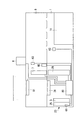
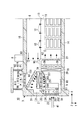
図1は、第一実施形態に係る外気取入空調システム10の構成を示す。第一実施形態に係る外気取入空調システム10は、平屋構造のデータセンタ3内に設けられたIT機器室(空調空間)1内の空調を行うものであり、このIT機器室1と隣接して空調機械室2を設けている。図1の例では、空調機械室2をIT機器室1の一方に配置した例を示したが、IT機器室1の両側に空調機械室2を配置して、双方からIT機器室1内の空調を行っても良い。
<First embodiment>
[Constitution]
FIG. 1 shows a configuration of an outside air intake
空調機械室2は、IT機器室1の天井13とほぼ同じ高さで水平方向に仕切られ、上方の排気プレナムチャンバ21と下方の給気プレナムチャンバ22を有する。
The air
空調機械室2の外壁31には、外気空気を取り入れるための外気取入部23が設けられ、外気取入部23は外気取入ガラリ24と外気制御ダンパ25と外気取入部23を区画するケーシングを有している。なお、図1では、外気取入ガラリ24を外側、外気制御ダンパ25を室内側(外気取り入れ方向下流側)に設けているが、外気制御ダンパ25を外側、外気取り入れガラリ24を室内側に設けても良い。
The
外気制御ダンパ25は、取り入れる外気の量を制御するために開閉される。外気制御ダンパ25は、例えば外気空気41の取入方向(x方向)と直交する方向(本例では水平方
向(z方向))の回動軸251と、当該回動軸251を中心に回動する羽252とを複数備え、不図示のモータによって羽252を外気空気41の取入方向と直交する位置に回動させることで開口を閉じ(全閉状態)、羽252を外気空気41の取入方向と平行な位置へ回動させることで開口を開く(全開状態)、また、この全開状態と全閉状態の間で羽252の回動位置を調整することで開口面積を調整する。
The outside
外気取入部23の室内側には、空気分配体兼用フィルタ5を接続している。外気取入部23と空気分配体兼用フィルタ5とは気密に接続され、外気取入部から取り入れられた外気空気41は、全て空気分配体兼用フィルタ5を介して給気プレナムチャンバ22へ流入する。空気分配体兼用フィルタ5は、通過する外気空気41の塵埃の除去、化学物質の吸着・分解などを行い、IT機器室1に送る空気の清浄度を所定範囲に維持する。なお、空気分配体兼用フィルタ5の構成は、後段で詳述する。
An
給気プレナムチャンバ22と排気プレナムチャンバ21の仕切り部分(還流部)、即ち給気プレナムチャンバ22の上方には還気制御ダンパ26が設けられている。還気制御ダンパは、IT機器室1からの還気空気を再度IT機器室1へ還流させる量を制御するために開閉される。還気制御ダンパ26は、例えば還気空気を給気プレナムチャンバ22へ取り入れる還気空気42の流入方向(y方向)と直交する方向(本例では水平方向(z方向))の回動軸261と、当該回動軸261を中心に回動する羽262とを複数備え、不図示のモータによって羽262を還気空気42の流入方向と直交する位置に回動させることで開口を閉じ(全閉状態)、羽262を還気空気42の流入方向と平行な方向へ回動させることで開口を開く(全開状態)。即ち、外気制御ダンパ25を閉じ、還気制御ダンパ26を開ける方向へ調整することで還気量を増やす。一方、外気制御ダンパ25を開ける方向へ調整し、還気制御ダンパ26を閉じる方向へ調整することで還気量を減らす。
A return
また、給気プレナムチャンバ22とIT機器室1とを仕切る壁に吹出口27を設け、給気プレナムチャンバ22内の吹出口27近傍に循環ファン28が設けられている。循環ファン28は、常時稼働し、還気空気や外気空気を給気プレナムチャンバ22から吹出口27を介してIT機器室1へ送風する。なお、循環ファン28の上流側には整流体29を設け、循環ファン28へ流入する空気の流れを整えている。循環ファン28の送風により、IT機器室1内は、陽圧に保たれ、循環ファン28以外からの空気の流入や逆流が防止されている。
Further, an
IT機器室1には、サーバやスイッチ、ルータ、交換機といった発熱する機器を収納したラック11が設置されている。ラック11は、図1の紙面と垂直方向に所定間隔をあけて設けられている。この複数のラック11の間に吹出口27から吹き出した低温の空気が流入し、各機器或いはラック11に設けられたファンの動作によってラック11内に低温の空気が引き込まれ、ラック11内の機器を冷却する。機器の冷却により温められた空気は、ラック11から排出され、IT機器室1の天井13に設けられた吸込口12へ吸い込まれる。IT機器室1の天井13は、天井スラブ15との間に所定の間隔をあけて、床スラブ14と天井スラブ15との間の空間を仕切り、この天井裏に還気流路6を形成している。
The
天井13の吸込口12に吸い込まれた空気は、還気流路6を通り、還気として空調機械室2の排気プレナムチャンバ21に還流される。
The air sucked into the
排気プレナムチャンバ21のIT機器室1との仕切り部付近には、熱交換器7が設けられている。熱交換器7は、室外に設けた熱源8からの熱媒体を用いて、還気流路6から排気プレナムチャンバ21へ流入する還気と熱交換することにより還気を冷却する。なお、図1では、便宜上熱源8をIT機器室1の直上に図示したが、これはIT機器室(空調エ
リア)1毎に熱源8を設ける構成に限定するものではなく、中央熱源(不図示)から複数の空調エリアの熱交換器7へ熱媒体を供給する構成であっても良い。また、熱源8は、冷凍機を用いる構成であっても、冷凍機を用いずに冷却塔等で熱媒体を冷却する所謂フリークーリングを行う構成であっても良い。本例では、熱交換器7と循環ファン28とを垂直方向に並べて2段としたことにより、熱交換器7を循環ファン28の前後に配置するよりもコンパクトに構成している。即ち、熱交換器7と循環ファン28を垂直に投影して見た場合の占有面積(所謂フットプリント)をコンパクトにできる。また、熱交換器7を上段に配して天井裏を有効に利用でき、下段側のスペースを確保できる。
A
熱交換器7の還気流入方向上流側には、加湿装置95が設けられている。加湿装置95は、還気空気が所定の湿度を保つように、例えば気化式加湿器により還気空気に噴霧し加湿する。このように本例では、高温の還気空気に加湿するので、水分が速やかに蒸発し、ミストでIT機器室1内を濡らす恐れが無い。
A
排気プレナムチャンバ21の外壁側或いは天井側(本例では上方の天井スラブ15側)には、排気を排出する排出部9が設けられている。排出部9は、天井スラブ15に設けた開口151に嵌め込まれた排気制御ダンパ91や、開口151の上方を覆う雨蓋92、排気制御ダンパ91の排気方向下流側に設けられて雨水や異物の進入を防止する排気ガラリ93を有している。なお、本例では排気制御ダンパ91の排気方向下流側に排気ガラリ93を設けたが、排気ガラリ93を上流側、排気制御ダンパ91を下流側に設けても良い。
On the outer wall side or ceiling side of the exhaust plenum chamber 21 (in this example, the
排気制御ダンパ91は、排気する空気の量を制御する。排気制御ダンパ91は、例えば排気方向96と直交する回動軸911と、当該回動軸911を中心に回動する羽912とを複数備え、不図示のモータによって羽912を排気方向96と直交する位置に回動させることで開口を閉じ(全閉状態)、羽912を排気方向96と平行な方向へ回動させることで開口を開き(全開状態)、この全開状態と全閉状態の間で羽912の回動位置を調整することで開口面積を調整する。
The
排気プレナムチャンバ21内には、ガイドベーン94が設けられている。ガイドベーン94は、水平に流入する還気空気を下方の給気プレナムチャンバ22側へ導く湾曲した導風板を有し、還気が偏流を招くことなく給気プレナムチャンバ22へ流れるようにガイドする。
A
なお、上記構成とは別に、保守作業員のため、全還気運転時に対人用新鮮外気を取り入れる外調機を設けても良い。この場合に取り入れる新鮮空気は、別系統から循環空気の10%以下の量とするのが良い。 In addition to the above-described configuration, an external air conditioner that takes in fresh fresh air for personal use may be provided for a maintenance worker. In this case, the fresh air to be taken in is preferably 10% or less of the circulating air from another system.
制御装置80は、外気取入空調システム10の各部を制御することにより、外気取入空調システム10の運転状態を制御する。本実施形態において、制御装置80は、外気制御ダンパ25、還気制御ダンパ26、排気制御ダンパ91、循環ファン28、熱交換器7,70、冷却塔8、加湿装置95等の各部を制御する。
The
特に、制御装置80は、外気制御ダンパ25、還気制御ダンパ26、及び排気制御ダンパ91の開閉制御を行うことで、全還気運転や、全外気運転、混気運転といった運転状態を切り替える。
In particular, the
例えば、制御装置80は、以下の条件に応じて各ダンパ25,26,91を制御する。なお、具体的な処理のフローについては後述する。
For example, the
条件1:外気エンタルピが室内還気空気のエンタルピより高い又は外気湿度が所定温湿
度範囲の上限湿度より高い。ここで、室内還気空気のエンタルピは、例えば熱交換器7の上流側に温湿度センサを配置して検出する。また、外気エンタルピは、例えば屋外や外気取入部23に温湿度センサを配置して検出する。
Condition 1: The outside air enthalpy is higher than the enthalpy of indoor return air or the outside air humidity is higher than the upper limit humidity of the predetermined temperature and humidity range. Here, the enthalpy of the indoor return air is detected by arranging a temperature / humidity sensor on the upstream side of the
条件1を満たす場合には、外気制御ダンパ25及び排気制御ダンパ91を全閉状態とし、還気制御ダンパ26を全開状態とする。
When the
これにより、外気制御ダンパ25からの外気の導入及び排気制御ダンパ91からの排気は無く、循環ファン28でIT機器室1に送り出された空気が、還気流路6、排気プレナムチャンバ21、そして全開の還気制御ダンパ26を経て給気プレナムチャンバ22に全て戻り、循環路途中の熱交換器7で冷却され循環ファン28によって再循環されて、全還気運転が行われる。なお、所定温湿度範囲とは、IT機器室1に収容される機器の仕様によって許容或いは推奨される温湿度に基づいて予め設定された温湿度の範囲である。
As a result, there is no introduction of outside air from the outside
条件2:外気の温度及び湿度が、所定温湿度範囲内である。
条件2を満たす場合、外気制御ダンパ25及び排気制御ダンパ91を全開状態とし、還気制御ダンパ26を全閉状態とする。また、熱交換器7への冷却水の供給を停止し、熱交換は行わない。
Condition 2: The temperature and humidity of the outside air are within a predetermined temperature and humidity range.
When the
これにより外気制御ダンパ25を介して取り入れられた外気空気が、循環ファン28でIT機器室1に送られ、IT機器室内の冷却に寄与したのち、還気流路6を経て排気プレナムチャンバ21に達する。そして、排気プレナムチャンバ21の空気は、還気制御ダンパ26が全閉であるので給気プレナムチャンバ22へ戻らず、全て排気制御ダンパ91を介して排出部9から排出され、全外気運転が行われる。
As a result, the outside air taken in via the outside
条件3:条件1,2以外
条件3の場合、例えば外気空気の湿度が所定温湿度範囲の下限湿度より低い場合、還気制御ダンパ26を全開状態とし、外気制御ダンパ25及び排気制御ダンパ91の開閉度合いを調整する。即ち、外気制御ダンパ25の開口面積を全開状態よりも小さくして、外気の取入量を制限し、排気制御ダンパ91の開口面積を調整して排気プレナムチャンバ21を陽圧に保ちつつ、外気取入部23から取り入れた分の空気を排出する。また、加湿装置95により還気空気に加湿し、還気空気の湿度を調節する。
Condition 3: Other than
そして、湿度が調整された還気空気が、全開の還気制御ダンパ26を介して給気プレナムチャンバ22へ送られ、外気空気と混合されて循環ファン28によってIT機器室1に供給され、混気運転が行われる。
Then, the return air whose humidity has been adjusted is sent to the
[空気分配体兼用フィルタ5]
上記条件3の場合に、IT機器室1内を均一な温湿度に維持するためには、取り入れた外気空気と還気空気とを十分に混合させて均一な温湿度の給気を生成する必要がある。
[Air distributor combined filter 5]
In the case of
そこで本実施形態の外気取入空調システム10では、空気分配体兼用フィルタ5を給気プレナムチャンバ22に配置した。
Therefore, in the outside air intake
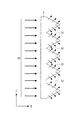
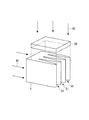
図2は、空気分配体兼用フィルタ5の模式斜視図、図3は空気分配体兼用フィルタ5のx−z断面図である。空気分配体兼用フィルタ5は、外気空気41の取入方向(x方向)下流側の面に還気空気42の流入方向(還気流入方向(本例ではy方向))に長手の溝部51を有し、当該溝部51が還気流入方向と直交する断面(x−z断面)において外気空気41の取入方向上流側に向かってその幅が減少する(収束する)凹形状となっている。
FIG. 2 is a schematic perspective view of the air distributor combined
そして、空気分配体兼用フィルタ5の溝部51内を下降する還気空気42と外気取入部23から取り入れられた外気空気41が直交する関係となっている。
The
このように、空気分配体兼用フィルタ5が溝部51を有しているため、外気空気41は、空気分配体兼用フィルタ5を通過する際、図3に示すように還気流入方向と直交する断面(x−z断面)においてフィルタ吹出面側部、例えば傾斜側部から溝部51に分配され、溝部51の内向きに偏向される。この場合に、溝部51の或る面から内向きに流出した外気空気は、対向する面から流出した外気空気とぶつかり、循環ファン28側へ移動する勢いが減衰する。このため、下降する還気空気42と効率良く混合する。ここで、還気制御ダンパ26から下降する還気空気42が空気分配体兼用フィルタ5の谷部内へ流入するのを遮り、還気空気42を溝部51へ導くため、図4に示すように空気分配体兼用フィルタ5の上端面に空気を通さない蓋(遮蔽部材)52を設けても良い。また、本実施形態では、図1に示したように空気分配体兼用フィルタ5の上端部から還気制御ダンパ26側と循環ファン28側とを隔てる塞板221を設け、還気空気42を空気分配体兼用フィルタ5の溝部51へ導く構成としている。
なお、図17に示すように還気制御ダンパ26の下方全域、即ち還気空気42が流入する領域の全体にわたって空気分配体兼用フィルタ5の溝部51を設けても良い。この場合、塞板221は設けなくてもよい。
Thus, since the air distributor combined
As shown in FIG. 17, the
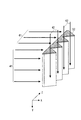
図5は、空気分配体兼用フィルタ5を複数配置した例を示す図である。図5の例では、還気制御ダンパ26の直下、即ち下降する還気空気42と交わる位置に、外気空気41の取入方向(x方向)へ所定間隔を空けて空気分配体兼用フィルタ5を複数配置した。このように、空気分配体兼用フィルタ5を増やすこと、即ち溝部51を増やすことで、外気空気41の勢いを減衰させる箇所を増やし、外気空気41と還気空気42とを更に均質に混合することができる。
FIG. 5 is a diagram showing an example in which a plurality of air distributor combined
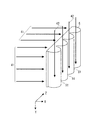
また、図6は空気分配体兼用フィルタ5を還気空気42の流入方向(y方向)に対して所定の角度をつけて配置した例を示す図である。
FIG. 6 is a view showing an example in which the air distributor combined
図6の例では、空気分配体兼用フィルタ5の上部(還気空気42の流入方向)を外気空気41の取入方向上流側に倒し、空気分配体兼用フィルタ5の溝部51を設けた面51Aを斜め上方に向けて配置している。これにより空気分配体兼用フィルタ5と交わる還気空気42が増え、溝部51を通る還気空気42が増えるので、更に効果的に外気空気41と還気空気42とが混合される。
In the example of FIG. 6, the upper surface of the air distributor combined filter 5 (inflow direction of the return air 42) is tilted to the upstream side in the intake direction of the
また、図6の例では、還気空気42が、空気分配体兼用フィルタ5の溝部51を通る際、空気分配体兼用フィルタ5の傾斜に沿って吹出口27側に導かれるため、還気空気42の流れがスムーズになる。
Further, in the example of FIG. 6, the
還気流入方向(y方向)に対する空気分配体兼用フィルタ5の傾斜角度αは、例えば、還気流入方向(y方向)と循環ファン28による吹出方向(x方向)とのなす角βの1/2とする。図6の例では還気空気42の取入方向(y方向)と循環ファン28による吹出方向(x
方向)とのなす角βが、90度であるので、空気分配体兼用フィルタ5の傾斜角度αを4
5度としている。なお、空気分配体兼用フィルタ5の傾斜角度αは、空気分配体兼用フィルタ5と循環ファン28との位置関係や給気プレナムチャンバ22内の構造等に応じて任意に設定できる。
The inclination angle α of the air distributor /
Since the angle β formed with the direction) is 90 degrees, the inclination angle α of the air distributor /
5 degrees. The inclination angle α of the air distributor combined
なお、図2−図6の例では、溝部51のx−z断面がV字の例を示したが、これに限らず、空気分配体兼用フィルタ5の溝部51の形状は、x−z断面において溝部51の幅が外気空気41の取入方向(x方向)上流側に向けて減少する形状であれば良い。
2 to 6, an example in which the xz cross section of the
図7は、溝部51を他の形状とした例を示す空気分配体兼用フィルタ5の模式斜視図である。なお、図7ではx−z断面の溝部51の形状が図4のジグザグ状に替えてU字の例を示した。この場合でも前述の図2−図6の例と同様に、外気空気41が溝部51に向けて分配され、溝部51内で外気空気がぶつかり、循環ファン28側へ移動する外気空気の勢いが減衰するので、溝部51を下降する還気空気42と効率良く混合できる。
FIG. 7 is a schematic perspective view of the air distributor combined
[空調方法]
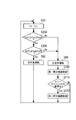
図8は、上記構成の外気取入空調システム10における空調方法のフローを示す図、図9は、外気取入空調システム10の各部を制御して図8の空調方法を実現する制御装置80の機能ブロック図、図10は、外気取入空調システム10の制御系統を示す図である。
[Air conditioning method]
FIG. 8 is a diagram showing a flow of an air conditioning method in the outside air intake
図10に示すように、制御装置80は、外気取入空調システム10の各部と電気的に接続している。図10において、61は外気取入部23に設けた温湿度センサであり、外気の温度及び湿度を検出する。62はIT機器室1に設けた温湿度センサであり、IT機器室1内の温度及び湿度を検出する。63は還気流路中に設けた温湿度センサであり、還気空気の温度及び湿度を検出する。
As shown in FIG. 10, the
また、制御装置80は、図9に示すように、マイクロプロセッサ(MPU)84やメインメモリ85、記憶部86、入出力部83等を有する所謂コンピュータである。
Further, as shown in FIG. 9, the
入出力部83は、外気取入空調システム10の各部と電気的に接続するインターフェイスであり、温湿度センサ(検出部)61,62,63からの検出値の入力、外気制御ダンパ25、還気制御ダンパ26、及び排気制御ダンパ91に対する開閉制御信号の出力、循環ファン28、熱交換器7、熱源8、加湿装置95に対する動作制御信号の出力等を行う。また、入出力部83には、ユーザの操作によって設定値等が入力される操作部や、運転状態等を表示する表示部も接続されている。
The input /
記憶部86は、フラッシュメモリやハードディスク等の記憶手段(補助記憶装置)であり、演算処理のためのOS(オペレーティングシステム)やファームウェア(空調制御プログラム)を記憶している。また、記憶部86は、IT機器室内を目的の温湿度範囲に制御するための設定データ(外気温湿度の上限値や下限値等)を記憶している。
The
MPU84は、メインメモリ(主記憶装置)85を介して前記OSやソフトウェアを記憶部86から適宜読み出して実行し、空調制御プログラムに従って入出力部83から入力された情報や、記憶部86から読み出した情報を演算処理することにより、温湿度情報取得部65や、モード決定部66、ダンパ制御部67、加湿制御部68、熱交換制御部69としても機能する。
The
この温湿度情報取得部65は、温湿度センサ61,62,63による検出値に基づいて、外気の温湿度や、IT機器室内の温湿度、還気空気の温湿度を取得する。
The temperature / humidity information acquisition unit 65 acquires the temperature / humidity of the outside air, the temperature / humidity in the IT equipment room, and the temperature / humidity of the return air based on the detection values of the temperature /
モード決定部66は、温湿度情報取得部65で取得した温湿度の情報に基づいて、選択すべき運転状態(運転モード)を決定する。具体的には、所定の制御条件を満たしているか否かに応じて全還気運転や、全外気運転、混気運転といった運転モードを決定する。
The
ダンパ制御部67は、モード決定部66によって決定した運転モードに応じて外気制御ダンパ25、還気制御ダンパ26、及び排気制御ダンパ91に対して開閉制御信号を送ることで各ダンパの開閉を制御する。
The
加湿制御部68は、モード決定部66によって決定した運転モードに応じて加湿装置95へ加湿制御信号を送り、還気空気に対して加湿させ、IT機器室内の湿度が所定範囲内となるように制御する。
The
熱交換制御部69は、熱交換器7への熱媒体の供給を制御して、熱交換器7による熱交換量を制御する。
The heat
図9に示した本実施形態の制御装置80は、MPU84がソフトウェア(空調制御プログラム)に従って処理を実行するコンピュータであり、このソフトウェアで温湿度情報取得部65や、モード決定部66、ダンパ制御部67、加湿制御部68、熱交換制御部69の機能を実現するが、これに限らず、温湿度情報取得部65や、モード決定部66、ダンパ制御部67、加湿制御部68、熱交換制御部69の機能を専用のハードウェアで実現した装置であっても良い。
The
ここでハードウェアは、例えば、FPGA[Field Programmable Gate Array]、AS
IC[Application Specific Integrated Circuit]、LSI[Large Scale Integration]といった回路で実現することも可能である。また、当該ハードウェアは、IC[Integrated Circuit]、ゲートアレイ、論理回路、信号処理回路、アナログ回路といった基本的な回路で実現することも可能である。
Here, the hardware is, for example, FPGA [Field Programmable Gate Array], AS.
It can also be realized by a circuit such as an IC [Application Specific Integrated Circuit] or an LSI [Large Scale Integration]. The hardware can also be realized by basic circuits such as an IC [Integrated Circuit], a gate array, a logic circuit, a signal processing circuit, and an analog circuit.
論理回路としては、例えば、AND回路(論理積回路)、OR回路(論理和回路)、NOT回路(否定回路)、NAND回路(否定的論理積回路)、NOR回路(否定的論理和回路)、フリップフロップ回路、カウンタ回路がある。信号処理回路には、信号値に対し、例えば、加算、乗算、除算、反転、積和演算、微分、積分を実行する回路がある。アナログ回路には、例えば、信号値に対して、増幅、加算、乗算、微分、積分を実行する回路がある。 As the logic circuit, for example, an AND circuit (logical product circuit), an OR circuit (logical sum circuit), a NOT circuit (negative circuit), a NAND circuit (negative logical product circuit), a NOR circuit (negative logical sum circuit), There are flip-flop circuits and counter circuits. The signal processing circuit includes a circuit that performs, for example, addition, multiplication, division, inversion, product-sum operation, differentiation, and integration on a signal value. Analog circuits include, for example, circuits that perform amplification, addition, multiplication, differentiation, and integration on signal values.
そして、管理者の操作によって電源が投入されると、制御装置80は図8の処理を開始する。先ず、制御装置80のMPU84は、温湿度センサ61からの検出値に基づいて外気空気の温度(乾球温度)taと外気空気の絶対湿度twを取得する(S10)。なお、絶対湿度は、温湿度センサ61が絶対湿度を検出する構成であっても良いし、温湿度センサ61が相対湿度を検出してMPU84(温湿度情報取得部65)が絶対湿度に換算する構成であっても良い。
Then, when the power is turned on by the administrator's operation, the
次に、MPU84は、外気空気の絶対湿度twが上限値twH以下か否かを判定する(S20)。なお、絶対湿度の上限値twHとは、IT機器室内に設置されるIT機器の仕様によって決定される値である。
Next, the
外気空気の絶対湿度twが上限値twH以下であれば(S20,Yes)、MPU84は、外気空気の温度taが全外気運転の上限温度tafH以下か否かを判定する(S30)。なお、全外気運転の上限温度tafHとは、全外気運転を行った場合に、IT機器室1内の温度が、目的の温度範囲の上限値となる外気の温度であり、IT機器室1内に設置されるIT機器の発熱量や循環ファン28による送風量等に基づいて設定される。
If the absolute humidity tw of the outside air is equal to or lower than the upper limit value twH (S20, Yes), the
外気空気の温度taが全外気運転の上限温度tafH以下であれば(S30,Yes)、MPU84は、外気空気の温度taが全外気運転の下限温度tafL以上か否かを判定する(S40)。なお、全外気運転の下限温度tafLとは、全外気運転を行った場合に、IT機器室1内の温度が、目的の温度範囲の下限値となる外気の温度であり、IT機器室1内に設置されるIT機器の発熱量や循環ファン28による送風量等に基づいて設定される。
If the temperature ta of the outside air is equal to or lower than the upper limit temperature tafH of the all outside air operation (S30, Yes), the
外気空気の温度taが全外気運転の下限温度tafL以上であれば(S40,Yes)、MPU84は、外気空気の絶対湿度twが下限値twL以上か否かを判定する(S50)。なお、絶対湿度の下限値twLとは、IT機器室内に設置されるIT機器の仕様によって決定される値である。
If the temperature ta of the outside air is equal to or higher than the lower limit temperature tafL of all outside air operation (S40, Yes), the
そして、外気空気の絶対湿度twが下限値twL以上であれば(S50,Yes)、MPU84は、モード決定部66の機能により、前述の条件2を満たしたと判定して運転モードを全外気運転と決定し、ダンパ制御部67の機能により、外気制御ダンパ25及び排気制御ダンパ91を全開状態、還気制御ダンパ26を全閉状態とする(S60)。また、MPU84は、熱交換器7への冷却水の供給を停止させ、熱交換を行わないよう制御する。
If the absolute humidity tw of the outside air is equal to or higher than the lower limit value twL (S50, Yes), the
このように外気が所定の温湿度の範囲にあれば、取り入れた外気を循環ファン28でIT機器室1に供給することでIT機器の冷却を行えるので、当該制御により外気冷房を行う。なお、ステップS60の制御を行った後は、ステップS10に戻って処理を繰り返す。
As described above, if the outside air is in the predetermined temperature and humidity range, the IT device can be cooled by supplying the taken outside air to the
一方、ステップS20で外気空気の絶対湿度が上限値twHを超えていた場合、或いはステップS30で外気空気の温度が上限値tafHを超えていた場合、MPU84は、モード決定部66の機能により、前述の条件1を満たしたと判定して運転モードを全還気運転と決定し、ダンパ制御部67の機能により、外気制御ダンパ25及び排気制御ダンパ91を全閉状態とし、還気制御ダンパ26を全開状態とする(S90)。
On the other hand, when the absolute humidity of the outside air exceeds the upper limit value twH in step S20, or when the temperature of the outside air exceeds the upper limit value tafH in step S30, the
また、MPU84は、温湿度情報取得部65の機能により温湿度センサ62,63の検
出値を取得し、IT機器室1内が目的の温湿度範囲内となるように、熱交換制御部69の機能により熱交換器7への熱媒体(冷却水)の供給量を調整して熱交換量を制御する(S100)。なお、熱交換器7は、還気空気を冷却することにより、還気空気の除湿も行う。
Further, the
このように外気温度taが上限値tafHを超えている場合、或いは外気の絶対湿度が上限値twHを超えている場合、外気冷房を行えないので、全還気運転とし、熱交換器7で還気空気を冷却することによりIT機器室1内を目的の温湿度範囲に制御する。なお、ステップS100の制御を行った後は、ステップS10に戻って処理を繰り返す。
As described above, when the outside air temperature ta exceeds the upper limit value tafH, or when the absolute humidity of the outside air exceeds the upper limit value twH, the outside air cooling cannot be performed. The inside of the
また、ステップS40で外気温度taが下限値tafL未満の場合、或いはステップS50で外気空気の絶対湿度twが下限値twL未満の場合、MPU84は、モード決定部66の機能により、前述の条件3の場合であると判定して運転モードを混気運転と決定し、ダンパ制御部67の機能により、還気制御ダンパ26を全開状態とし、外気制御ダンパ25及び排気制御ダンパ91の開閉度合いを調整する(S70)。この外気制御ダンパ25と排気制御ダンパ91の開閉度合いによって、IT機器によって暖められた還気空気と低温の外気空気との混合比が調整され、IT機器室内が目的の温度範囲に保たれる。
When the outside air temperature ta is lower than the lower limit value tafL in step S40, or when the absolute humidity tw of the outside air air is lower than the lower limit value twL in step S50, the
また、MPU84は、温湿度情報取得部65の機能により温湿度センサ62,63の検
出値を取得し、IT機器室1内が目的の湿度範囲内となるように、加湿制御部68の機能により、加湿装置95を制御し、還気空気に加湿させる。
Further, the
このように外気温度taが下限値tafL未満、或いは外気空気の絶対湿度twが下限値twL未満であって、全外気運転に適さない状況であっても、外気空気と還気空気を混合することによって、IT機器室内を目的の温湿度範囲に空調することができ、外気冷房の適用期間を拡大することができる。 In this way, even when the outside air temperature ta is less than the lower limit value tafL, or the absolute humidity tw of the outside air is less than the lower limit value twL and is not suitable for all outside air operation, the outside air and the return air are mixed. As a result, the IT equipment room can be air-conditioned to the target temperature and humidity range, and the application period of the outside air cooling can be extended.
また、本実施形態では、空気分配体兼用フィルタ5を用いたことにより、限られた空間内で効果的に外気空気41と還気空気42とを混合することができ、空調エリア内の温湿度のバラツキを抑えることができる。また、外気空気41と還気空気42とを効率良く混合できることから、IT機器室1の床下空間にプレナムチャンバを形成する必要がなく外気取入空調システムをコンパクトに構成できる。
Further, in the present embodiment, the use of the air distributor combined
〈変形例1〉
図11は、本変形例1の概略構成図、図12は本変形例1の空調方法の説明図である。
<
FIG. 11 is a schematic configuration diagram of the first modification, and FIG. 12 is an explanatory diagram of the air conditioning method of the first modification.
本変形例1は、前述の実施形態1と比べ、熱交換器としてフリークーリングを行う第一熱交換器7Aと、フリークーリングではない第二熱交換器7Bを設けた構成が異なり、その他の構成は同じである。このため、同一の要素に同符号を付すなどして重複する説明を省略した。
Compared with the above-described first embodiment, the first modification differs in the configuration in which the
第一熱交換器7Aは前述の熱交換器7と同様に、排気プレナムチャンバ21のIT機器室1との仕切り部に設けられ、還気空気を冷却する。なお、第一熱交換器7Aは、冷却塔(不図示)で外気によって放熱させた熱媒体(冷却水)を用いて、還気流路6から排気プレナムチャンバ21へ流入する還気空気と熱交換することにより、当該還気空気のフリークーリングを行う。
Like the
また、第二熱交換器7Bは、給気プレナムチャンバ22において循環ファン28の上流側に設けられ、冷凍機(不図示)で冷却した熱媒体を用いて、IT機器室1への給気空気を冷却する。
The
次に本変形例1の空調方法について、図12を用いて説明する。なお、図12に示す本変形例1の空調方法のフローは、図8と比べて全還気運転を行う場合のステップS100以降の処理が異なり、その他は同じであるため、全還気運転についてのみ説明する。
Next, the air-conditioning method of this
ステップS20で外気空気の絶対湿度が上限値twHを超えていた場合、或いはステップS30で外気空気の温度が上限値tafHを超えていた場合、MPU84は、モード決定部66の機能により、前述の条件1を満たしたと判定して運転モードを全還気運転と決定し、ダンパ制御部67の機能により、外気制御ダンパ25及び排気制御ダンパ91を全閉状態とし、還気制御ダンパ26を全開状態とする(S90)。
When the absolute humidity of the outside air exceeds the upper limit value twH in step S20, or when the temperature of the outside air exceeds the upper limit value tafH in step S30, the
また、MPU84は、温湿度情報取得部65の機能により温湿度センサ62,63の検
出値、及び熱媒体(冷却水)の温度を取得し、当該温度の冷却水を用いて還気空気との熱交換を行った場合にIT機器室1内が目的の温湿度範囲内となるように、熱交換制御部69の機能により第一熱交換器7Aへの冷却水の供給量を調整して熱交換量を制御する(S100)。
Further, the
更に、MPU84は、熱交換制御部69の機能により、フリークーリングによる冷却が限界に達したか否かを判定する(S110)。なお、フリークーリングによる冷却が限界に達したか否かは、例えば冷却水の流量を100%とした場合に温湿度センサ62の検出値(IT機器室1内の温度)が上限を超えている場合や、冷却水の温度が、還気空気と熱交換してIT機器室1内を目的温度範囲に保つ為に必要な温度の上限値を超えた場合に、限界に達したと判定する。
Further, the
フリークーリングによる冷却が限界に達していないと判定した場合には(S110,No)、ステップS10に戻って処理を繰り返し、限界に達したと判定した場合には(S1
10,Yes)、第二熱交換器7Bへの熱媒体の供給する冷凍機(不図示)を制御し、第二熱交換器7Bによる還気空気との熱交換量を増減してIT機器室1内を目的温度範囲に保つように制御する(S120)。ステップS120後は、ステップS10に戻って処理を繰り返す。
When it is determined that the cooling by free cooling has not reached the limit (S110, No), the process returns to step S10 and is repeated, and when it is determined that the limit has been reached (S1)
10, Yes), control the refrigerator (not shown) for supplying the heat medium to the
上記のように本変形例1によれば、全還気運転を選択した場合にフリークーリングを行い、フリークーリングによる冷却が限界に達した場合にのみ冷凍機を用いた冷却を行うことにより、外気冷熱の利用期間を更に拡大でき、高い省エネルギー効果が得られる。例えば、外気の絶対湿度twが高く、全外気運転や混気運転が行えない場合であっても、外気温度taが低ければフリークーリングによってIT機器室内を目的温度範囲に保つことができる。 As described above, according to the first modification, free cooling is performed when the total return air operation is selected, and cooling using the refrigerator is performed only when the cooling by free cooling reaches the limit. The use period of cold heat can be further expanded, and a high energy saving effect is obtained. For example, even if the absolute humidity tw of the outside air is high and the entire outside air operation or the mixed air operation cannot be performed, if the outside air temperature ta is low, the IT equipment room can be kept in the target temperature range by free cooling.
なお、図12では、ステップS40において、外気温度taが下限値tafL以下と判定した場合に、運転モードを混気運転とする例を示したが、これに限らず、気温度taが下限値tafL以下の場合に、運転モードを全還気運転とし、ステップS90に移行しても良い。この場合、下限値tafLは、フリークーリングによって全還気運転が可能になる外気温度の上限値としても良い。これにより外気温度taが低く下限値tafL未満の場合には全還気運転を行い、中間期で外気温度taが目的温度と近く、下限値tafL以上、上限値tafH以下の場合には全外気運転或いは混気運転を行う。 FIG. 12 shows an example in which the operation mode is the mixed operation when the outside air temperature ta is determined to be equal to or lower than the lower limit value tafL in step S40. However, the present invention is not limited to this. In the following cases, the operation mode may be the full return air operation, and the process may proceed to step S90. In this case, the lower limit value tafL may be an upper limit value of the outside air temperature at which full return air operation is possible by free cooling. Thus, when the outside air temperature ta is low and less than the lower limit value tafL, the total return air operation is performed, and when the outside air temperature ta is close to the target temperature in the intermediate period and is lower than the lower limit value tafL and lower than the upper limit value tafH, the entire outside air operation is performed. Alternatively, mixed air operation is performed.
なお、本変形例1において、第一熱交換器7Aは、図11に示すように排気プレナムチャンバ21のIT機器室1との仕切り部に設けられたが、これに限らず還気空気と熱交換できる位置に設けられれば良い。例えば図13は、第一熱交換器7Aを排気プレナムチャンバ21と給気プレナムチャンバ22との仕切り部に設けた例を示す。
In the first modification, the
〈参考例〉
図14は本参考例の空調方法の説明図である。本参考例は、前述の変形例1と比べ、運転モードを全外気運転又は全還気運転の何れかを選択する構成が異なり、その他の構成は同じである。例えば、本参考例の機器構成は、図11,図13に示した変形例1と同じである。但し、フィルタ5は、空気分配体兼用のものでなく粉塵や有害な化学物質を除去する一般的なフィルタを用いることができる。
<Reference example>
FIG. 14 is an explanatory diagram of the air conditioning method of this reference example. This reference example is different from the above-described first modification in the configuration for selecting either the all-outside air operation or the all-return air operation as the operation mode, and the other configurations are the same. For example, the device configuration of this reference example is the same as that of the first modification shown in FIGS. However, the
管理者の操作によって電源が投入され、図14の処理を開始すると、制御装置80のMPU84は、温湿度センサ61からの検出値に基づいて外気空気の温度(乾球温度)taと外気空気の絶対湿度twを取得する(S10)。
When the power is turned on by the operation of the administrator and the processing of FIG. 14 is started, the
次に、MPU84は、外気空気の絶対湿度twが所定範囲内か、即ち上限値twH以下で且つ下限値twL以上か否かを判定する(S20A)。
Next, the
外気空気の絶対湿度twが所定範囲内であれば(S20A,Yes)、MPU84は、外気空気の温度taが所定範囲内か、即ち全外気運転の上限温度tafH以下で且つ下限温度tafLか否かを判定する(S30A)。この場合、下限値tafLは、フリークーリングによって全還気運転が可能になる外気温度の上限値とする。
If the absolute humidity tw of the outside air is within the predetermined range (S20A, Yes), the
外気空気の温度taが所定範囲内であれば(S30A,Yes)、MPU84は、モード決定部66の機能により、運転モードを全外気運転と決定し、ダンパ制御部67の機能により、外気制御ダンパ25及び排気制御ダンパ91を全開状態、還気制御ダンパ26を全閉状態とする(S60)。また、MPU84は、熱交換器7A,7Bへの冷却水の供給を停止させ、熱交換を行わないよう制御する。
If the temperature ta of the outside air is within the predetermined range (S30A, Yes), the
このように外気が所定の温湿度の範囲にあれば、取り入れた外気を循環ファン28でIT機器室1に供給することでIT機器の冷却を行えるので、当該制御により外気冷房を行う。なお、ステップS60の制御を行った後は、ステップS10に戻って処理を繰り返す。
As described above, if the outside air is in the predetermined temperature and humidity range, the IT device can be cooled by supplying the taken outside air to the
一方、ステップS20Aで外気空気の絶対湿度twが所定範囲から外れていた場合、或いはステップS30Aで外気空気の温度が所定範囲から外れていた場合、MPU84は、モード決定部66の機能により、運転モードを全還気運転と決定し、ダンパ制御部67の機能により、外気制御ダンパ25及び排気制御ダンパ91を全閉状態とし、還気制御ダンパ26を全開状態とする(S90)。
On the other hand, if the absolute humidity tw of the outside air is out of the predetermined range in step S20A, or if the temperature of the outside air is out of the predetermined range in step S30A, the
また、MPU84は、温湿度情報取得部65の機能により温湿度センサ62,63の検
出値、及び熱媒体(冷却水)の温度を取得し、当該温度の冷却水を用いて還気空気との熱交換を行った場合にIT機器室1内が目的の温湿度範囲内となるように、熱交換制御部69の機能により第一熱交換器7Aへの冷却水の供給量を調整して熱交換量を制御し、フリークーリングを行う(S100)。
Further, the
更に、MPU84は、熱交換制御部69の機能により、フリークーリングによる冷却が限界に達したか否かを判定する(S110)。なお、フリークーリングによる冷却が限界に達したか否かは、例えば冷却水の流量を100%とした場合に温湿度センサ62の検出値(IT機器室1内の温度)が上限を超えている場合や、冷却水の温度が、還気空気と熱交換してIT機器室1内を目的温度範囲に保つ為に必要な温度の上限値を超えた場合に、限界に達したと判定する。
Further, the
フリークーリングによる冷却が限界に達していないと判定した場合には(S110,No)、ステップS10に戻って処理を繰り返し、限界に達したと判定した場合には(S110,Yes)、第二熱交換器7Bへの熱媒体の供給する冷凍機(不図示)を制御し、第二熱交換器7Bによる還気空気との熱交換量を調整してIT機器室1内を目的温度範囲に保つように制御する(S120)。ステップS120後は、ステップS10に戻って処理を繰り返す。
If it is determined that the cooling by free cooling has not reached the limit (S110, No), the process returns to step S10 and the process is repeated. If it is determined that the limit has been reached (S110, Yes), the second heat The refrigerator (not shown) that supplies the heat medium to the
上記のように本参考例によれば、外気温度taが低く下限値tafL未満の場合にはフリークーリングを行い、中間期で外気温度taが目的温度と近く、下限値tafL以上、上限値tafH以下の場合には全外気運転を行うので、フリークーリングが可能な期間に加えて、外気温度taが目的温度と近い中間期においても全外気運転によって外気冷熱を利用できるので、高い省エネルギー効果が得られる。 As described above, according to this reference example, when the outside air temperature ta is low and less than the lower limit value tafL, free cooling is performed, and in the intermediate period, the outside air temperature ta is close to the target temperature, and is lower than the lower limit value tafL and lower than the upper limit value tafH. In this case, since the entire outside air operation is performed, in addition to the period during which free cooling is possible, the outside air cooling can be used by the all outside air operation even in the intermediate period when the outside air temperature ta is close to the target temperature, so that a high energy saving effect is obtained .
また、外気冷房により高い省エネルギー効果を得ながら、外気を取り入れる期間を最小限(中間期のみ)に抑えられる為、黄砂の飛来や、火山の噴火、台風等の影響によって、外気中に塵埃や、海塩、ガス物質が多く含まれる場合であっても影響が少ない。 In addition, while obtaining high energy saving effect by outside air cooling, the period of taking in outside air can be suppressed to the minimum (only in the intermediate period), so dust and dirt in the outside air can be affected by the impact of yellow sand, volcanic eruption, typhoon, etc. Even if it contains a lot of sea salt and gas substances, it has little effect.
<第二実施形態>
図15,図16は、外気取入空調システム10の第二実施形態を示す図である。本第二実施形態の外気取入空調システム10は、多層階構造のデータセンタ30に適用した例を示す。前述の第一実施形態では排出部9を空調機械室2の上方に設けたが、本第二実施形態では、外気に通じる排気シャフト側に設けた構成が異なっている。なお、前述の第一実施形態と同一の機能を有する要素には同符号を付すなどして重複する説明を省略し、前述の第一実施形態と異なる構成について主に説明する。
<Second embodiment>
FIGS. 15 and 16 are diagrams showing a second embodiment of the outside air intake
本第二実施形態の外気取入空調システム10では、IT機器室1の両側の端部に空調機
械室2を設け、IT機器室1の中間に外気に通じる排気シャフト90を設けている。
In the outside air intake
本第二実施形態の排出部9は、還気流路6の排気シャフト90側に設けられている。排出部9は、排気ガラリ93を排気方向下流側に有し、その上流側に排気制御ダンパ91を有している。
The
また、空調機械室2とIT機器室1との仕切り部分、即ち熱交換器7の上流側或いは下流側近傍(図15では下流側)に還気制御ダンパ26を設けている。
Further, a return
そして、データセンタ30の屋上に複数階分の熱源(冷却塔等)8をまとめて配置している。
A plurality of floors of heat sources (cooling towers, etc.) 8 are arranged together on the roof of the
循環ファン28によってIT機器室1に送出した空気はラック11内の機器を冷却したのち、天井13の吸込口12へ吸い込まれ、還気流路6を介して空調機械室2へ戻る。空調機械室2に戻った還気空気は、熱交換器7そして還気制御ダンパ26を介し、ガイドベーン94で下向きに導風される。この下向きに導風された還気空気は、前述と同様に空気分配体兼用フィルタ5の溝部51を下降し、外気取入部23から取り入れた外気空気と効果的に混合される。なお、本第二実施形態では、還気制御ダンパ26とガイドベーン94が還気空気42を外気空気41と交差する方向で流入させる還流部を構成している。
The air sent to the
本第二実施形態では、空調機械室2の還気制御ダンパから下流側が給気プレナムチャンバ22として機能する。
In the second embodiment, the downstream side of the return air control damper of the air
全還気運転、全外気運転、外気取入量制御及び加湿制御運転に伴う各ダンパ25,26,91の制御は、前述と同じである。
The control of each
図15,図16に示す多層階構造のデータセンタにおいて、図1に示した第一実施形態と同様に空調機械室2の上方に排気プレナムチャンバ21を設けてその外壁側に排出部9を設けた場合、即ち外気取入部23と排出部9を同一の外壁に垂直方向に並べて配置すると、下階の排出部9から排出した空気を上階の外気取入部23から取り入れてしまい、排気空気のショートサーキットが生じる可能性がある。
15 and 16, the multi-story data center is provided with an
このため、本第二実施形態では、図16に示すように、データセンタ30の外壁に各階の外気取入部23を配置し、排気シャフト90側に各階の排出部9を配置してショートサーキットを防止している。
For this reason, in the second embodiment, as shown in FIG. 16, the outside
以上、本発明の好適な実施形態を説明したが、本発明に係る冷却システムはこれらに限らず、可能な限りこれらの組合せを含むことができる。 Although the preferred embodiments of the present invention have been described above, the cooling system according to the present invention is not limited to these, and can include combinations thereof as much as possible.
1…IT機器室、
10…外気取入空調システム、
11…ラック、
12…吸込口、
13…天井、
14…床スラブ
15…天井スラブ、
151…開口、
2…空調機械室、
21…排気プレナムチャンバ、
22…給気プレナムチャンバ、
23…外気取入部、
24…外気取入ガラリ、
25…外気制御ダンパ、
251…回動軸、
252…羽、
26…還気制御ダンパ、
261…回動軸、
262…羽、
27…吹出口、
28…循環ファン、
29…整流体、
3,30…データセンタ、
31…外壁、
41…外気空気、
42…還気空気、
5…空気分配体兼用フィルタ、
51…溝部、
52…蓋、
6…還気流路、
61…温湿度センサ、
62…温湿度センサ、
65…温湿度情報取得部、
66…モード決定部、
67…ダンパ制御部、
68…加湿制御部、
69…熱交換制御部、
7…熱交換器、
7A…第一熱交換器、
7B…第二熱交換器、
8…熱源、
80…制御装置、
83…入出力部、
84…MPU、
85…メインメモリ、
86…記憶部、
9…排出部、
90…排気シャフト、
91…排気制御ダンパ、
911…回動軸、
912…羽、
92…雨蓋、
93…排気ガラリ、
94…ガイドベーン、
95…加湿装置、
96…排気方向、
1 ... IT equipment room,
10 ... Outside air intake air conditioning system,
11 ... Rack,
12 ... Suction port,
13 ... ceiling,
14 ...
151. Opening,
2 ... Air conditioning machine room,
21 ... Exhaust plenum chamber,
22 ... Air supply plenum chamber,
23 ... Outside air intake section,
24 ... Garari for taking in outside air,
25 ... outside air control damper,
251 ... Rotating shaft,
252 ... feathers,
26 ... Return air control damper,
261 ... rotating shaft,
262 ... feathers,
27 ... Air outlet,
28 ... circulation fan,
29 ... rectifier,
3, 30 ... data center,
31 ... Outer wall,
41 ... Outside air,
42 ... return air,
5 ... Air distributor filter
51 ... groove,
52 ... lid,
6 ... Return air flow path,
61 ... temperature / humidity sensor,
62 ... temperature / humidity sensor,
65 ... temperature and humidity information acquisition unit,
66 ... mode decision unit,
67 ... Damper control unit,
68 ... Humidification control unit,
69 ... heat exchange control unit,
7 ... heat exchanger,
7A ... first heat exchanger,
7B ... Second heat exchanger,
8 ... heat source,
80 ... control device,
83 ... input / output unit,
84 ... MPU,
85 ... Main memory,
86: Storage unit,
9 ... discharge section,
90 ... exhaust shaft,
91 ... Exhaust control damper,
911 ... Rotating shaft,
912 ... feathers,
92 ... rain cover,
93 ... exhaust louver,
94 ... Guide vane,
95 ... Humidifier,
96 ... exhaust direction,
Claims (8)
送風機の上流側に設けた給気チャンバと、
前記給気チャンバに屋外から外気を取り入れて所定の外気流入方向へ流入させる外気取入部と、
前記空調空間からの還気を前記給気チャンバへ前記外気と交差する方向で流入させる還流部と、
前記外気を前記外気流入方向に透過させて、当該外気中の夾雑物を捕集するフィルタと、
を備え、
前記フィルタの外気流入方向下流側の面に、前記還気の流入方向に長手の溝部を設け、当該溝部が前記還気の流入方向と直交する断面において前記外気流入方向上流側に向けて収束する形状である外気取入空調システム。 A blower that blows air to the air-conditioned space;
An air supply chamber provided upstream of the blower;
An outside air intake section for taking outside air into the air supply chamber from the outside and allowing it to flow in a predetermined outside air inflow direction;
A recirculation unit for allowing return air from the air-conditioned space to flow into the air supply chamber in a direction crossing the outside air;
A filter that permeates the outside air in the direction of inflow of the outside air and collects contaminants in the outside air; and
With
A groove that is long in the return air inflow direction is provided on the downstream surface of the filter in the outside air inflow direction, and the groove converges toward the outside in the outside air inflow direction in a cross section orthogonal to the inflow direction of the return air. An outside air intake air conditioning system that is shaped.
前記還気を屋外へ排出する排出部と、
前記外気取入部及び前記還流部にそれぞれ設けたダンパの開閉を制御して運転状態を選択的に制御する制御部と、を備え、
前記制御部が、外気の状態に応じて、
前記外気取入部のダンパを開、前記還流部のダンパを閉とし、前記外気取入部から取り入れた外気を前記送風機で前記空調空間に送風し、当該空調空間を経た空気を全て前記排出部から排出させる全外気運転と、
前記外気取入部のダンパを閉、前記還流部のダンパを開とし、外気を取り入れずに、前記還流部から前記給気チャンバに還流した還気を前記空調空間へ送風し、当該空調空間を経た還気を全て前記還気流路及び前記還流部を介して前記給気チャンバに還流させる全還気運転と、
前記外気取入部のダンパの開閉状態を調整して外気の取り入れ量を制限すると共に、前記還流部のダンパを閉とし、前記外気取入部から前記給気チャンバに取り入れた外気と前記還流部から前記給気チャンバに流入させた還気とが混合した空気を前記送風機で前記空調空間に送風する混気運転と、
の何れかを選択する請求項1から3の何れか一項に記載の外気取入空調システム。 A return air flow path that leads the air that has passed through the air-conditioned space as return air to the reflux section;
A discharge section for discharging the return air to the outdoors;
A control unit that selectively controls the operating state by controlling the opening and closing of dampers provided in the outside air intake unit and the reflux unit, respectively.
According to the outside air state, the control unit
The damper of the outside air intake part is opened, the damper of the reflux part is closed, the outside air taken in from the outside air intake part is blown to the air-conditioned space by the blower, and all the air passing through the air-conditioned space is discharged from the exhaust part With all outside air driving,
The damper of the outside air intake part is closed, the damper of the reflux part is opened, and the return air returned from the reflux part to the supply chamber is blown to the air-conditioned space without taking in outside air, and passes through the air-conditioned space. A total return air operation for returning all return air to the supply chamber via the return air flow path and the return part;
The open / close state of the damper of the outside air intake unit is adjusted to limit the intake amount of outside air, and the damper of the reflux unit is closed, and the outside air taken into the supply chamber from the outside air intake unit and the return unit from the return unit An air-mixing operation in which the air mixed with the return air flowing into the air supply chamber is blown to the air-conditioned space by the blower;
The outside air intake air conditioning system according to any one of claims 1 to 3, wherein any one of the above is selected.
前記外気の絶対湿度が前記所定範囲未満であり、前記外気の温度が前記所定範囲内である場合に、前記制御部が前記混気運転を選択し、前記加湿装置により前記還気に加湿させ
る請求項5又は6に記載の外気取入空調システム。 A humidifier for humidifying the return air;
When the absolute humidity of the outside air is less than the predetermined range and the temperature of the outside air is within the predetermined range, the control unit selects the mixed air operation and humidifies the return air by the humidifier. Item 7. The outside air intake air conditioning system according to Item 5 or 6.
Priority Applications (1)
| Application Number | Priority Date | Filing Date | Title |
|---|---|---|---|
| JP2011040798A JP5571603B2 (en) | 2011-02-25 | 2011-02-25 | Outside air intake air conditioning system |
Applications Claiming Priority (1)
| Application Number | Priority Date | Filing Date | Title |
|---|---|---|---|
| JP2011040798A JP5571603B2 (en) | 2011-02-25 | 2011-02-25 | Outside air intake air conditioning system |
Publications (2)
| Publication Number | Publication Date |
|---|---|
| JP2012177521A true JP2012177521A (en) | 2012-09-13 |
| JP5571603B2 JP5571603B2 (en) | 2014-08-13 |
Family
ID=46979466
Family Applications (1)
| Application Number | Title | Priority Date | Filing Date |
|---|---|---|---|
| JP2011040798A Active JP5571603B2 (en) | 2011-02-25 | 2011-02-25 | Outside air intake air conditioning system |
Country Status (1)
| Country | Link |
|---|---|
| JP (1) | JP5571603B2 (en) |
Cited By (7)
| Publication number | Priority date | Publication date | Assignee | Title |
|---|---|---|---|---|
| JP2013053828A (en) * | 2011-09-06 | 2013-03-21 | Nihon Sekkei Inc | Building, air conditioning system, and data center |
| WO2015102247A1 (en) * | 2014-01-06 | 2015-07-09 | 네이버비즈니스플랫폼 주식회사 | Server room cooling device, filter module for introducing outer air, and data center air-conditioning system comprising same |
| JP2016205688A (en) * | 2015-04-21 | 2016-12-08 | 富士通株式会社 | Duct and data center |
| CN108168012A (en) * | 2016-12-07 | 2018-06-15 | 无锡天云数据中心科技有限公司 | A kind of data center's energy conserving system |
| JP2019015436A (en) * | 2017-07-05 | 2019-01-31 | 株式会社竹中工務店 | Air conditioning system |
| JP2019219085A (en) * | 2018-06-18 | 2019-12-26 | 新日本空調株式会社 | Replacement type air conditioning device |
| JP7546885B2 (en) | 2020-07-01 | 2024-09-09 | 株式会社トルネックス | Rapid ventilation air circulation adjustment system |
Citations (4)
| Publication number | Priority date | Publication date | Assignee | Title |
|---|---|---|---|---|
| JPS53120380U (en) * | 1977-03-02 | 1978-09-25 | ||
| JPH05296532A (en) * | 1992-04-15 | 1993-11-09 | Kubota Corp | Surrounding air conditioner |
| JPH07305864A (en) * | 1994-05-09 | 1995-11-21 | Tokyo Gas Co Ltd | Suction box provided with air cleaning function |
| JP2010261696A (en) * | 2009-11-30 | 2010-11-18 | Kajima Corp | Outside air cooling type air conditioner for computer room |
-
2011
- 2011-02-25 JP JP2011040798A patent/JP5571603B2/en active Active
Patent Citations (4)
| Publication number | Priority date | Publication date | Assignee | Title |
|---|---|---|---|---|
| JPS53120380U (en) * | 1977-03-02 | 1978-09-25 | ||
| JPH05296532A (en) * | 1992-04-15 | 1993-11-09 | Kubota Corp | Surrounding air conditioner |
| JPH07305864A (en) * | 1994-05-09 | 1995-11-21 | Tokyo Gas Co Ltd | Suction box provided with air cleaning function |
| JP2010261696A (en) * | 2009-11-30 | 2010-11-18 | Kajima Corp | Outside air cooling type air conditioner for computer room |
Cited By (11)
| Publication number | Priority date | Publication date | Assignee | Title |
|---|---|---|---|---|
| JP2013053828A (en) * | 2011-09-06 | 2013-03-21 | Nihon Sekkei Inc | Building, air conditioning system, and data center |
| WO2015102247A1 (en) * | 2014-01-06 | 2015-07-09 | 네이버비즈니스플랫폼 주식회사 | Server room cooling device, filter module for introducing outer air, and data center air-conditioning system comprising same |
| CN105829807A (en) * | 2014-01-06 | 2016-08-03 | Naver商务平台株式会社 | Server room cooling device, filter module for introducing outer air, and data center air-conditioning system comprising same |
| US20160353612A1 (en) * | 2014-01-06 | 2016-12-01 | Naver Business Platform Corporation | Server room cooling device, filter module for introducing outer air, and data center air-conditioning system comprising same |
| US10492338B2 (en) | 2014-01-06 | 2019-11-26 | Naver Business Platform Corporation | Server room cooling device, filter module for introducing outer air, and data center air-conditioning system comprising same |
| JP2016205688A (en) * | 2015-04-21 | 2016-12-08 | 富士通株式会社 | Duct and data center |
| CN108168012A (en) * | 2016-12-07 | 2018-06-15 | 无锡天云数据中心科技有限公司 | A kind of data center's energy conserving system |
| JP2019015436A (en) * | 2017-07-05 | 2019-01-31 | 株式会社竹中工務店 | Air conditioning system |
| JP7169051B2 (en) | 2017-07-05 | 2022-11-10 | 株式会社竹中工務店 | air conditioning system |
| JP2019219085A (en) * | 2018-06-18 | 2019-12-26 | 新日本空調株式会社 | Replacement type air conditioning device |
| JP7546885B2 (en) | 2020-07-01 | 2024-09-09 | 株式会社トルネックス | Rapid ventilation air circulation adjustment system |
Also Published As
| Publication number | Publication date |
|---|---|
| JP5571603B2 (en) | 2014-08-13 |
Similar Documents
| Publication | Publication Date | Title |
|---|---|---|
| JP5571603B2 (en) | Outside air intake air conditioning system | |
| JP5932350B2 (en) | Air conditioning apparatus and air conditioning control method | |
| CN104755850B (en) | Modular data center and control method therefor | |
| JP5543181B2 (en) | Outside air-cooling computer room air conditioner | |
| TWI457522B (en) | Energy saving air condition system and air condition mode thereof | |
| JP5397107B2 (en) | Humidity control equipment | |
| CN104541108A (en) | Direct evaporative air handler | |
| US20220146123A1 (en) | Air treatment system | |
| JP2004354040A (en) | Ventilation and air conditioning system | |
| WO2013057844A1 (en) | Air conditioning system of communication/information processing apparatus chamber, etc. | |
| JP2005172309A (en) | Blower and air conditioning system for room | |
| JP4651460B2 (en) | Air conditioner and outside air cooling operation method | |
| JP2006125825A (en) | Ventilation device | |
| US10701836B2 (en) | System for cooling computing devices of a plurality of facilities | |
| KR100747802B1 (en) | Ventilating apparatus and controlling method of the same | |
| GB2540139B (en) | Combined ventilation, cooling and humidification system and method | |
| JP4478004B2 (en) | Air conditioner | |
| CN215765407U (en) | Indoor unit of air conditioner | |
| KR102684036B1 (en) | Air conditioning system | |
| JP2002156148A (en) | Humidifying method for air conditioning | |
| JP3808237B2 (en) | Humidification method and humidifier for air conditioning | |
| KR101563696B1 (en) | Humidifying and Ventilating Apparatus | |
| JP7150493B2 (en) | air conditioner | |
| JP4203462B2 (en) | Air conditioning system and air conditioning method | |
| KR102575089B1 (en) | Air conditioning system |
Legal Events
| Date | Code | Title | Description |
|---|---|---|---|
| A621 | Written request for application examination |
Free format text: JAPANESE INTERMEDIATE CODE: A621 Effective date: 20131224 |
|
| A977 | Report on retrieval |
Free format text: JAPANESE INTERMEDIATE CODE: A971007 Effective date: 20140528 |
|
| TRDD | Decision of grant or rejection written | ||
| A01 | Written decision to grant a patent or to grant a registration (utility model) |
Free format text: JAPANESE INTERMEDIATE CODE: A01 Effective date: 20140617 |
|
| A61 | First payment of annual fees (during grant procedure) |
Free format text: JAPANESE INTERMEDIATE CODE: A61 Effective date: 20140626 |
|
| R150 | Certificate of patent or registration of utility model |
Ref document number: 5571603 Country of ref document: JP Free format text: JAPANESE INTERMEDIATE CODE: R150 |