JP3808237B2 - Humidification method and humidifier for air conditioning - Google Patents
Humidification method and humidifier for air conditioning Download PDFInfo
- Publication number
- JP3808237B2 JP3808237B2 JP13403599A JP13403599A JP3808237B2 JP 3808237 B2 JP3808237 B2 JP 3808237B2 JP 13403599 A JP13403599 A JP 13403599A JP 13403599 A JP13403599 A JP 13403599A JP 3808237 B2 JP3808237 B2 JP 3808237B2
- Authority
- JP
- Japan
- Prior art keywords
- air
- steam
- humidification
- water
- air conditioner
- Prior art date
- Legal status (The legal status is an assumption and is not a legal conclusion. Google has not performed a legal analysis and makes no representation as to the accuracy of the status listed.)
- Expired - Lifetime
Links
Images


Landscapes
- Central Air Conditioning (AREA)
- Ventilation (AREA)
Description
【0001】
【発明の属する技術分野】
本発明は、半導体その他の埃を嫌う物品を製造する作業場(クリーンルーム)や環境試験室などの被空調室にあって、換気のために導入される外気の湿度不足分を省エネルギ的に補うために利用される。
【0002】
【従来の技術】
わが国においては、冬期や中間期において、この季節に導入する換気用の外気の湿度不足を補う必要があり、この導入外気に対し外気処理用空調機、すなわち外調機を設けて加熱加湿処理を行ない、また高温多湿の夏季はこの外調機で冷却除湿を行なっている。例えば特開平9−79611号公報の装置にあっては、外調機内の上流側に水噴霧器、下流側に蒸気噴出器を配置すると共に、該水噴霧器の前後に冬期に高温の媒体を通すコイルが配置してあり、外気が低温低湿の季節は、該コイルによって外気及び噴霧を加熱し、更に蒸気噴出により加湿している。
【0003】
しかし、蒸気加湿装置は、蒸気発生装置が高価で、エネルギ消費量も大であるから、装置がなるべく小規模であると共に蒸気使用量が少ないことが望ましい。
【0004】
【発明が解決しようとする課題】
本発明は、新設又は既設の外調機を備える空調手段にあって、蒸気による加湿量を少なくし、水による加湿の比率を高めて、装置コスト及び加湿コストを低下させることを課題とする。
【0005】
【課題を解決するための手段】
前記課題を解決するための加湿方法は、請求項1に記載したとおり、被空調室を出た空気を熱交換器によって調温し、さらに被空調室に循環させ、この循環系の外に設けた外調機に吸入した外気を外調機中で蒸気加湿して外気ダクトを介して前記被空調室への循環空気に混合する空調用加湿方法において、前記循環空気の流通経路であって熱交換器側に水を噴霧して形成したミストと前記循環空気とを混合する加湿手段を設け、外調機中の蒸気加湿を制御する蒸気弁の開度を制御し、蒸気弁の開度が10%以内及び10%前後のいずれかとなるように併せて加湿手段を制御することにより、全加湿量の大部分をこの水の噴霧による加湿量とし、その余を外調機内で蒸気加湿することを特徴とする。この手段によれば、被空調室内からの還気の顕熱を水加湿によって潜熱に置き換えることが可能であり、加湿の大部分を運転費が安い水加湿とし、加湿の一部を精密な制御ができる蒸気加湿としたので、良好な制御性を維持しながら省エネルギの加湿を達成できる。
【0006】
また加湿方法の第2の手段は、請求項2に記載したとおり、請求項1において、外気ダクト及び被空調室に湿度センサが設けられており、これら二つの湿度センサから発生する湿度信号で外調機の蒸気加湿量を制御すると共に、該湿度信号を水噴霧量の制御に兼用させることを特徴とする。この手段によれば、一つの湿度制御装置を用いて蒸気と純水の制御を行なわせることができる。
【0007】
また前記課題を解決するための加湿装置は、請求項3に記載したとおり、熱交換器を被空調室への循環空気路中に設置し、前記被空調室の外に蒸気加湿器をもつ外調機を設け、熱交換器で調温された調和空気を被空調室に送風機によって循環させ、換気用の外気を外調機に導入して蒸気加湿したのち空調機に流入させるべくした空調用加湿装置において、被空調室の床下又は隣室にリターンチャンバを設け、リターンチャンバ内に上流側から、水噴霧装置と、外調機からの調温調湿空気の吐出口と、高性能フィルタと、表面に結露が生じないように制御された乾式熱交換器とを順次設置して還気し、外調機の蒸気加湿を制御可能な蒸気弁の開度を制御し、蒸気弁の開度が10%以内及び10%前後のいずれかとなるように併せて水噴霧装置が制御可能になっており、蒸気弁の開度信号をもとに水噴霧装置の加湿量を制御装置で調節することを特徴とする。この手段によれば、請求項1の効果を達成する装置を提供することができ、水と蒸気のそれぞれを、室内の空気状態に応じて省エネルギ的に制御できる。
【0008】
また加湿装置の第2の手段は、請求項4に記載したとおり、請求項3において、水噴霧装置が、純水を供給する複数の純水弁を有しており、複数の純水弁のうち、次の純水弁が開弁するときには先行の純水弁の流量が一定に保持され、全体の水量がリニアに調節されることを特徴とする。
【0009】
【発明の実施の形態】
以下、図面を参照して本発明の実施の形態を説明する。図1において、1は建物、2は被空調室であるクリーンルームを示している。クリーンルーム2の床下はリターンチャンバ3とされ、該リターンチャンバ3の横にリターンシャフト4が連設されている。クリーンルーム2の天井部5には、超高性能(ULPA)フィルタが張設され、その上部の分配室6がリターンシャフト4に連通しており、クリーンルーム2の床7は、グレーチングからなる公知の構造で、通気性を有し還気を流通させる。温調装置8は、乾式熱交換器8aと送風機8bを備え、クリーンルーム2内の生産機器の廃熱などの内部発熱に対して冷却作用を行なう。送風機8bの下流側はダクト8cにより分配室6に連通している。9は高性能(HEPA)フィルタである。なお、乾式熱交換器8aは、表面に結露が生じないように制御された顕熱交換器とするのが望ましい。
【0010】
外調機10は、換気のために補給する外気OAを処理するための空調機で、これも既設のものであり、建物1に付設された囲壁11の端部に外気取入口12を有し、内部にプレヒータ13、冷却コイル14、加熱コイル15、蒸気加湿器16、送気ファン17を備え、これに接続された外気ダクト18の下流端18aは、リターンチャンバ3に開口し高性能(HEPA)フィルタ18bを備える。なお、図示はしないが、クリーンルーム2からは、生産装置その他で加熱された清浄空気の一部が排気ダクトを介して建物外に排気される。
【0011】
20は、本発明の要部を形成する純水噴霧装置で、3組の純水ミスト機21,22,23を有する。
【0012】
該純水ミスト機21〜23は、ダクト兼用の中空の支柱24に設置され、それぞれ噴霧器S1,S2,S3と旋回気流ガイドEを備える。
【0013】
支柱24内の仕切り24aの上下に、第1、第2のファンF1,F2が支柱24内面のダクトに送気できるように設置されている。噴霧器S1,S2,S3には、圧縮空気源Aからボール弁形式の圧空弁A1,A2,A3を介して圧縮空気が供給されると共に、純水源Wからリニア特性が良い二方弁形式の純水弁W1,W2,W3を介して純水が供給され、二流体式の噴霧を発生させる。3個の旋回気流ガイドEは、ファンF1,F2から送られる空気を各噴霧に対して旋回空気流として吹きつけて、噴霧を拡散すると共に水滴を微細化したミストMを発生させる。該ミストMは、クリーンルーム2から戻る還気と混合して気化する。更に送風機8bによってHEPAフィルタ9で再び清浄化され、乾式熱交換器8aに至る。なお、第1のファンF1は、上部2個の旋回気流ガイドEに送気し、第2のファンF 2 は、下端の旋回気流ガイドEに送気する。
【0014】
この建物の例では、クリーンルーム2の相対湿度を50%一定とすべく、給気露点温度をカスケード制御している。すなわち前記蒸気加湿器16に送る蒸気量を制御するために、制御装置25が設けられ、外気ダクト18に設けた湿度センサ26とクリーンルーム2に設けた湿度センサ27の信号が該装置25の指示調節器25aに入力され、該指示調節器25aから出る信号Aをモータドライバ28に伝え、モータドライバ28は信号Aを弁開度信号a1に変換して蒸気弁16aの開度を制御する。25bは制御の遅れを防止するカスケード設定器である。なお、モータドライバ28からの信号a1は、夏季など除湿を必要とする時期には、冷却コイル14の冷水入口近くに設けた二方弁の開度を制御することに用いられる。
【0015】
純水ミスト機21〜23で発生させるミスト量を制御するために、リターンチャンバ3側に純水制御装置29の指示調節器30とモータドライバ31,32,33が設けられ、純水ミスト機21〜23に設けた圧空弁A1〜A3と純水弁W1〜W3の開度を制御し、且つファンF1,F2の運転スイッチf1,f2を制御する。前記指示調節器30は、モータドライバ28から出力された蒸気弁の開度信号A1を受け、モータドライバ31,32,33に圧空弁、純水弁の各開度信号に変換した信号を送る。この信号値に応じて圧空弁と純水弁が制御される。
【0016】
なお、クリーンルーム2の天井5にファンフィルタユニットを配置して空気を循環させるべくしたいわゆるFFU方式では、リターンシャフト4内の送風機8bとダクト8cが不要になるから、このリターンシャフト4内に水加湿器20を設置してもよい。この際に、乾式熱交換器8aは、リターンシャフト4の出口すなわちその天井部近くに立設することもできるし、該乾式熱交換器8を各ファンフィルタユニットごとに分割したコイルとして、各ファンフィルタユニットに付設することができる。
【0017】
図2は、純水ミスト機20の各要素の動作を示すもので、横軸に水加湿要求値、縦軸に前記動作及び加湿量を示した。二方弁形式の純水弁W1〜W3は、開弁スタート点O1,O2,O3で順次開弁すると共に、スタート点O2,O3では先行の純水弁W1,W2の流量は一定値に保持し、全体の水量がリニアに調節される。このような特性が得られるのは、二方弁が良好なリニア特性をもつことによる。また、蒸気弁の開度が結果として10%以内となるように、圧空弁、純水弁の開度を制御する。これによる加湿量制御はPID制御とする。
【0018】
圧空弁A1〜A3は、純水弁W1〜W3と同期して開弁するが、第1のファンF1はスタート点O1で作動し、スタート点O2を経過後も単独で作動を続けて第1、第2の純水ミスト機21,22に送気し、スタート点O3で第2のファンF2が作動し、第3の純水ミスト機23に送気する。
【0019】
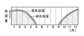
図3は、前記の装置における蒸気と純水の加湿量を示すもので、夏季以外は蒸気と純水の両方が使用されるが、蒸気は純水に比べて僅かで、実質上微調節分の加湿が蒸気によってなされており、既設の蒸気弁16aは、開度10%前後で制御される。そして一般に11月から4月までの冬期と中間期は、全加湿量の80%以上が純水による加湿とされ、寒冷地においては10月から5月まで同様の加湿が可能である。
【0020】
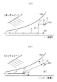
図4は、外気を導入したときの空気線図で、図4aは従来採用されていた加湿方法、図4bは本発明の加湿方法を示す。図4a,bにおいて、イは外調機10への外気導入点、ロは蒸気加湿器16を通過する点、ハはリターンチャンバ3内への給気点、ニはクリーンルーム2の状態点で24℃、湿度45%であり、ホは混合後の状態である。図4aの従来方法では、蒸気加湿で過飽和が生じないように、冷却コイル14を通る温水による加熱Iと温水コイル15による加熱IIをしたのち、蒸気加湿器16で蒸気放出IIIによる加湿が行なわれるから、補給した外気のエンタルピーが増大し、結果的に乾式熱交換機8aの負荷を増大している。
【0021】
これに対して図4bの方法では、冷却コイル14を通る温水による加熱Iは行なうが、温水コイル15による加熱はなるべく省略し、ロ点で少量の蒸気放出III′が行なわれ、湿度が少し上昇する。一方、クリーンルーム2からの還気は、純水ミスト加湿装置20から放出される純水によって、状態点ニが等エンタルピー変化して点への状態になり、これと点ハの加湿外気が混合することによりホの状態になる。この方法において、蒸気量を少なくしたことにより過飽和を避けるための加熱量を少なくすることができ、温水コイル15による加熱を実質上省略しエンタルピーの増大を防止し冷却用のエネルギを少なくすることができる。また蒸気量が少ないので蒸気発生用のエネルギが少なくてすむ。なお、本実施の形態では1台の送風機8bにより空気を循環させる方式を例にとっているが、クリーンルーム2の天井のULPAフィルタ5をファンフィルタユニットに変更すれば、送風機8bは不要となる。
【0022】
【発明の効果】
以上の説明から明らかなとおり、請求項1の手段によれば、加湿のための蒸気量を少なくしたので、蒸気発生のためのエネルギ及び過飽和予防のための加熱エネルギを少なくでき、運転費を加湿精度を確保しながら節約できる効果がある。また請求項2の手段によれば、純水噴霧量の制御に蒸気制御手段の信号を利用するので、純水噴霧量の制御が容易にできる。請求項3の手段によれば、蒸気制御装置で蒸気量及び純水量を制御するから、装置が簡単になる利点がある。また請求項4の手段によれば、リターンチャンバ内の空間を純水噴霧装置の設置に利用するので、空間を増設する必要がない利点がある。
【図面の簡単な説明】
【図1】 本発明の実施の形態の装置配置図
【図2】 純水噴霧装置の作動説明図
【図3】 加湿量説明図
【図4】 作用説明図
【符号の説明】
2 クリーンルーム 3 リターンチャンバ
4 リターンシャフト 5 天井部
8 空調機 8a 乾式熱交換器
10 外調機 16 蒸気加湿器
20 純水噴霧装置 25 蒸気制御装置
25a,30 指示調節器 26,27 湿度センサ
29 純水制御装置[0001]
BACKGROUND OF THE INVENTION
The present invention is in an air-conditioned room such as a workplace (clean room) or an environmental test room that manufactures semiconductors or other articles that do not like dust, and in order to save energy in a deficient amount of outside air introduced for ventilation. Used for
[0002]
[Prior art]
In Japan, it is necessary to compensate for the lack of humidity in the outside air for ventilation introduced in this season in the winter and intermediate periods, and the outside air treatment air conditioner, that is, the outside air conditioner, is provided for this introduced outside air for heating and humidification treatment. In the hot and humid summer, this external air conditioner cools and dehumidifies. For example, in the apparatus disclosed in Japanese Patent Laid-Open No. 9-79611, a coil for disposing a water sprayer on the upstream side in the external air conditioner and a steam sprayer on the downstream side and passing a high-temperature medium before and after the water sprayer in winter In the season when the outside air is at low temperature and low humidity, the outside air and the spray are heated by the coil, and further humidified by steam ejection.
[0003]
However, since the steam humidifier is expensive and consumes a large amount of energy, it is desirable that the apparatus is as small as possible and uses less steam.
[0004]
[Problems to be solved by the invention]
An object of the present invention is to provide an air conditioning unit including a new or existing external air conditioner, to reduce the amount of humidification by steam, increase the ratio of humidification by water, and reduce the apparatus cost and humidification cost.
[0005]
[Means for Solving the Problems]
The humidification method for solving the above-described problem is as described in
[0006]
Further, the second means of the humidifying method is that, as described in
[0007]
The humidifying apparatus for solving the above problems, as described in
[0008]
Further, the second means of the humidifier is as described in
[0009]
DETAILED DESCRIPTION OF THE INVENTION
Embodiments of the present invention will be described below with reference to the drawings. In FIG. 1, 1 is a building and 2 is a clean room which is an air-conditioned room. Under the floor of the
[0010]
The
[0011]
[0012]
The pure
[0013]
The first and second fans F 1 and F 2 are installed above and below the
[0014]
In this example of the building, the supply air dew point temperature is cascade controlled so that the relative humidity of the
[0015]
In order to control the amount of mist generated by the pure
[0016]
In the so-called FFU system in which a fan filter unit is arranged on the
[0017]
FIG. 2 shows the operation of each element of the pure
[0018]
The pneumatic valves A 1 to A 3 open in synchronization with the pure water valves W 1 to W 3 , but the first fan F 1 operates at the start point O 1 and remains alone after the start point O 2 has elapsed. Then, the operation continues to supply air to the first and second pure
[0019]
FIG. 3 shows the humidification amount of steam and pure water in the above-mentioned apparatus. Both steam and pure water are used except in summer, but the steam is slightly smaller than that of pure water, and is substantially finely adjusted. Humidification is performed by steam, and the existing
[0020]
FIG. 4 is an air diagram when outside air is introduced, FIG. 4a shows a humidification method conventionally employed, and FIG. 4b shows a humidification method of the present invention. 4a and 4b, a is a point for introducing the outside air into the
[0021]
On the other hand, in the method of FIG. 4b, the heating I by the hot water passing through the cooling coil 14 is performed, but the heating by the
[0022]
【The invention's effect】
As apparent from the above description, according to the means of
[Brief description of the drawings]
FIG. 1 is a device layout diagram according to an embodiment of the present invention. FIG. 2 is an operation explanatory diagram of a pure water spray device. FIG. 3 is a humidifying amount explanatory diagram. FIG. 4 is an operation explanatory diagram.
DESCRIPTION OF
Claims (4)
前記循環空気の流通経路であって熱交換器側に水を噴霧して形成したミストと前記循環空気とを混合する加湿手段を設け、
前記外調機中の蒸気加湿を制御する蒸気弁の開度を制御し、この蒸気弁の開度が10%以内及び10%前後のいずれかとなるように併せて前記加湿手段を制御することにより、全加湿量の大部分をこの水の噴霧による加湿量とし、その余を外調機内で蒸気加湿することを特徴とする空調用加湿方法。The air leaving the air-conditioned room is temperature-controlled by a heat exchanger and then circulated to the air-conditioned room. The outside air sucked into the external air conditioner provided outside this circulation system is steam-humidified in the external air conditioner. In the humidification method for air conditioning to be mixed with the circulating air to the air-conditioned room through a duct ,
A humidifying means for mixing the circulating air with the mist formed by spraying water on the heat exchanger side in the circulation path of the circulating air,
By controlling the opening of a steam valve that controls steam humidification in the external air conditioner, and controlling the humidifying means so that the opening of the steam valve is either within 10% or around 10%. A humidification method for air conditioning, characterized in that a majority of the total humidification amount is the humidification amount by spraying this water, and the remainder is steam humidified in an external air conditioner.
前記被空調室の床下又は隣室にリターンチャンバを設け、当該リターンチャンバ内に上流側から、水噴霧装置と、前記外調機からの調温調湿空気の吐出口と、高性能フィルタと、表面に結露が生じないように制御された乾式熱交換器とを順次設置して還気し、
前記外調機の蒸気加湿を制御可能な蒸気弁の開度を制御し、当該蒸気弁の開度が10%以内及び10%前後のいずれかとなるように併せて前記水噴霧装置が制御可能になっており、
前記蒸気弁の開度信号をもとに前記水噴霧装置の加湿量を制御装置で調節することを特徴とする空調用加湿装置。A heat exchanger is installed in the circulation air path to the air-conditioned room, an external air conditioner having a steam humidifier is provided outside the air-conditioned room, and conditioned air conditioned by the heat exchanger is supplied to the air-conditioned room. In a humidifier for air conditioning that is circulated by a blower, introduces the outside air for ventilation into the external air conditioner, humidifies the steam, and then flows into the air conditioner.
A return chamber is provided under or under the floor of the air-conditioned room, and from the upstream side in the return chamber, from the upstream side, a water spray device, a temperature-controlled humidity air discharge port from the external air conditioner, a high-performance filter, A dry heat exchanger controlled so as not to cause dew condensation is installed in order to return air,
The opening of a steam valve capable of controlling the steam humidification of the external air conditioner is controlled, and the water spray device can be controlled so that the opening of the steam valve is within 10% or around 10%. And
A humidifying device for air conditioning , wherein a humidifying amount of the water spray device is adjusted by a control device based on an opening signal of the steam valve .
Priority Applications (1)
| Application Number | Priority Date | Filing Date | Title |
|---|---|---|---|
| JP13403599A JP3808237B2 (en) | 1999-05-14 | 1999-05-14 | Humidification method and humidifier for air conditioning |
Applications Claiming Priority (1)
| Application Number | Priority Date | Filing Date | Title |
|---|---|---|---|
| JP13403599A JP3808237B2 (en) | 1999-05-14 | 1999-05-14 | Humidification method and humidifier for air conditioning |
Publications (3)
| Publication Number | Publication Date |
|---|---|
| JP2000329374A JP2000329374A (en) | 2000-11-30 |
| JP2000329374A5 JP2000329374A5 (en) | 2004-12-16 |
| JP3808237B2 true JP3808237B2 (en) | 2006-08-09 |
Family
ID=15118856
Family Applications (1)
| Application Number | Title | Priority Date | Filing Date |
|---|---|---|---|
| JP13403599A Expired - Lifetime JP3808237B2 (en) | 1999-05-14 | 1999-05-14 | Humidification method and humidifier for air conditioning |
Country Status (1)
| Country | Link |
|---|---|
| JP (1) | JP3808237B2 (en) |
Families Citing this family (7)
| Publication number | Priority date | Publication date | Assignee | Title |
|---|---|---|---|---|
| JP2002156137A (en) * | 2000-11-17 | 2002-05-31 | Takasago Thermal Eng Co Ltd | Air-conditioning humidifying equipment |
| JP4738807B2 (en) * | 2004-12-16 | 2011-08-03 | 株式会社テクノ菱和 | Air conditioning system for constant temperature and humidity |
| JP4954665B2 (en) * | 2005-10-19 | 2012-06-20 | 三機工業株式会社 | Proportional control method and apparatus for two-fluid water spray nozzle. |
| JP5416032B2 (en) * | 2010-05-19 | 2014-02-12 | 株式会社日立製作所 | Outside air type data center |
| JP5995337B1 (en) * | 2015-05-15 | 2016-09-21 | 木村工機株式会社 | Humidification unit |
| JP6298429B2 (en) * | 2015-09-07 | 2018-03-20 | ダイキン工業株式会社 | Air conditioning system for engine test room |
| JP6917139B2 (en) * | 2016-11-17 | 2021-08-11 | 株式会社竹中工務店 | Outside air treatment air conditioner |
Family Cites Families (7)
| Publication number | Priority date | Publication date | Assignee | Title |
|---|---|---|---|---|
| JPH0257844A (en) * | 1988-08-22 | 1990-02-27 | Hitachi Plant Eng & Constr Co Ltd | Humidity control method for clean room |
| JP2623488B2 (en) * | 1990-06-20 | 1997-06-25 | 鐘紡株式会社 | Water humidification method and device for air conditioning |
| JP3310118B2 (en) * | 1994-09-12 | 2002-07-29 | 高砂熱学工業株式会社 | Humidification method and air conditioning system |
| JP3375099B2 (en) * | 1994-09-19 | 2003-02-10 | 三機工業株式会社 | Air conditioner |
| JPH0979611A (en) * | 1995-09-13 | 1997-03-28 | Sony Corp | Air-conditioning device |
| KR100197900B1 (en) * | 1996-07-24 | 1999-06-15 | 윤종용 | Air-condition system using clean room of semiconductor |
| JPH10318571A (en) * | 1997-05-19 | 1998-12-04 | Ohbayashi Corp | Method for humidifying at the time of cooling with atmosphere |
-
1999
- 1999-05-14 JP JP13403599A patent/JP3808237B2/en not_active Expired - Lifetime
Also Published As
| Publication number | Publication date |
|---|---|
| JP2000329374A (en) | 2000-11-30 |
Similar Documents
| Publication | Publication Date | Title |
|---|---|---|
| JP3310118B2 (en) | Humidification method and air conditioning system | |
| KR102102831B1 (en) | Air conditioning system using indoor garden | |
| KR101825873B1 (en) | Heat pipe air conditioning plant using by-pass | |
| KR20140054879A (en) | Apparatus and method for cooling sever room using outside air | |
| JP2001317795A (en) | Air conditioner and humidity control method | |
| JP2001056146A (en) | Air conditioning apparatus | |
| JP3808237B2 (en) | Humidification method and humidifier for air conditioning | |
| KR101840588B1 (en) | Air conditioning plant using heat pipe | |
| JP2003139350A (en) | Dehumidifying air conditioner | |
| EP4375361A1 (en) | Air flow type solid state culture apparatus and air flow type solid state culture method | |
| JP2003294274A (en) | Constant temperature and humidity air-conditioning system | |
| JP2004245546A (en) | Air conditioning method and air conditioning device | |
| JP2002156148A (en) | Humidifying method for air conditioning | |
| JP2007198633A (en) | Air conditioning method, air conditioning equipment, and control method of air conditioning equipment | |
| JP2558552B2 (en) | Ventilation and air conditioning equipment | |
| JPH05288390A (en) | Outdoor air conditioner | |
| JPS5816136A (en) | Energy saving air conditioning system | |
| JP3429141B2 (en) | Air conditioner | |
| JP2007139336A (en) | Ventilation device and building | |
| JP2697655B2 (en) | Air conditioner | |
| JPH0989350A (en) | Method and apparatus for controlling humidity of air conditioner | |
| JP2001263724A (en) | Air-conditioning method and air conditioner | |
| JPH05196258A (en) | Air-conditioning facility | |
| KR200403658Y1 (en) | Humidifier for air conditioners and thermo-hygrostats | |
| JP2002333161A (en) | Dehumidifying air conditioning system |
Legal Events
| Date | Code | Title | Description |
|---|---|---|---|
| A521 | Written amendment |
Free format text: JAPANESE INTERMEDIATE CODE: A523 Effective date: 20040108 |
|
| A621 | Written request for application examination |
Free format text: JAPANESE INTERMEDIATE CODE: A621 Effective date: 20040108 |
|
| A977 | Report on retrieval |
Free format text: JAPANESE INTERMEDIATE CODE: A971007 Effective date: 20051019 |
|
| A131 | Notification of reasons for refusal |
Free format text: JAPANESE INTERMEDIATE CODE: A131 Effective date: 20051101 |
|
| A521 | Written amendment |
Free format text: JAPANESE INTERMEDIATE CODE: A523 Effective date: 20051228 |
|
| TRDD | Decision of grant or rejection written | ||
| A01 | Written decision to grant a patent or to grant a registration (utility model) |
Free format text: JAPANESE INTERMEDIATE CODE: A01 Effective date: 20060418 |
|
| A61 | First payment of annual fees (during grant procedure) |
Free format text: JAPANESE INTERMEDIATE CODE: A61 Effective date: 20060517 |
|
| R150 | Certificate of patent or registration of utility model |
Free format text: JAPANESE INTERMEDIATE CODE: R150 |
|
| FPAY | Renewal fee payment (event date is renewal date of database) |
Free format text: PAYMENT UNTIL: 20100526 Year of fee payment: 4 |
|
| FPAY | Renewal fee payment (event date is renewal date of database) |
Free format text: PAYMENT UNTIL: 20100526 Year of fee payment: 4 |
|
| FPAY | Renewal fee payment (event date is renewal date of database) |
Free format text: PAYMENT UNTIL: 20110526 Year of fee payment: 5 |
|
| FPAY | Renewal fee payment (event date is renewal date of database) |
Free format text: PAYMENT UNTIL: 20110526 Year of fee payment: 5 |
|
| FPAY | Renewal fee payment (event date is renewal date of database) |
Free format text: PAYMENT UNTIL: 20120526 Year of fee payment: 6 |
|
| FPAY | Renewal fee payment (event date is renewal date of database) |
Free format text: PAYMENT UNTIL: 20120526 Year of fee payment: 6 |
|
| FPAY | Renewal fee payment (event date is renewal date of database) |
Free format text: PAYMENT UNTIL: 20130526 Year of fee payment: 7 |
|
| FPAY | Renewal fee payment (event date is renewal date of database) |
Free format text: PAYMENT UNTIL: 20130526 Year of fee payment: 7 |
|
| FPAY | Renewal fee payment (event date is renewal date of database) |
Free format text: PAYMENT UNTIL: 20140526 Year of fee payment: 8 |
|
| S531 | Written request for registration of change of domicile |
Free format text: JAPANESE INTERMEDIATE CODE: R313531 |
|
| R350 | Written notification of registration of transfer |
Free format text: JAPANESE INTERMEDIATE CODE: R350 |
|
| EXPY | Cancellation because of completion of term |