JP2012176653A - Platform truck frame for rolling stock - Google Patents
Platform truck frame for rolling stock Download PDFInfo
- Publication number
- JP2012176653A JP2012176653A JP2011039953A JP2011039953A JP2012176653A JP 2012176653 A JP2012176653 A JP 2012176653A JP 2011039953 A JP2011039953 A JP 2011039953A JP 2011039953 A JP2011039953 A JP 2011039953A JP 2012176653 A JP2012176653 A JP 2012176653A
- Authority
- JP
- Japan
- Prior art keywords
- pipe
- bogie frame
- air spring
- airtight
- horizontal
- Prior art date
- Legal status (The legal status is an assumption and is not a legal conclusion. Google has not performed a legal analysis and makes no representation as to the accuracy of the status listed.)
- Granted
Links
Images


Abstract
Description
本発明は、側梁を貫通して接合された横梁に対し空気バネが設置され、その空気バネの補助空気室を側梁に設けた鉄道車両用台車枠であって、特に、横梁から側梁への流路を横梁内部に設けた鉄道車両用台車枠に関する。 The present invention relates to a bogie frame for a railway vehicle in which an air spring is installed on a lateral beam joined through a side beam, and an auxiliary air chamber of the air spring is provided on the side beam. The present invention relates to a bogie frame for a railway vehicle in which a flow path to the inside is provided in a horizontal beam.
従来の鉄道車両用台車枠には、例えばレール方向に沿って配置された2本の側梁と、枕木方向に沿って配置された前後2本の横梁とが連結された構成のものがある。こうした形状の鉄道車両用台車枠には、従来から様々な構造のものが提案されている。図8は、そのうちの一つであり、下記特許文献1に記載された鉄道車両用台車枠を示した図である。この鉄道車両用台車枠100は、レール方向に沿って配置され、その両端にバネ帽111を備えた側梁101に、2本の横梁102が枕木方向に貫通している。横梁102には丸形鋼管が使用され、平行に並べた2本の横梁102の両端部分が天板112と底板113によって一体に接合されている。横梁102が貫通した側梁101の台車外側位置には、天板112上に空気バネ座115が設けられ、そこに設置される左右一対の空気バネは、2本ある横梁102のいずれか一方ずつに接続され、それぞれの横梁102が補助空気室として利用される。
Conventional railcar bogie frames include, for example, a structure in which two side beams arranged along the rail direction and two front and rear side beams arranged along the sleeper direction are connected. Conventionally, various types of structures have been proposed for the bogie frame for a railway vehicle having such a shape. FIG. 8 is one of them, and is a diagram showing a bogie frame for a railway vehicle described in
図8に示した鉄道車両用台車枠100は、横梁102が2本のパイプで構成されているため、それぞれに空気バネの補助空気室を構成している。そのため、比較的簡単に空気バネと補助空気室との接続構造を構成することができる。しかし、例えば前記特許文献2,3の鉄道車両用台車枠のように1本の横梁によって構成されたものであって、その横梁上に空気バネが設置されているとすると、左右の空気バネに対応する補助空気室をつくるためには、横梁内を仕切り板で区切らなければならず、そのための溶接作業が非常に手間を要し、気密性を確保することも容易ではない。
In the
一方、鉄道車両用台車枠には、左右一対の側梁をそれぞれ補助空気室とするものがある。しかし、空気バネが側梁上にない場合、すなわち図8に示した鉄道車両用台車枠100のように空気バネ座115が側梁101の外側に位置しているような場合には、横梁102に設けた空気バネの給気口から側梁への接続流路が必要になる。しかし、そのための接続配管は、構造が複雑になってしまうと製造が難しくなる他、十分な気密性を確保することも困難になる。また、流路が外部配管によって構成するようなものは、車両走行中に飛び石が衝突して破損する可能性もある。
On the other hand, some railcar carriage frames use a pair of left and right side beams as auxiliary air chambers. However, when the air spring is not on the side beam, that is, when the
そこで本発明は、かかる課題を解決すべく、横梁上の空気バネと側梁内の補助空気室とを接続する簡易な構成の流路を有する鉄道車両用台車枠を提供することを目的とする。 SUMMARY OF THE INVENTION Accordingly, an object of the present invention is to provide a bogie frame for a railway vehicle having a flow path with a simple configuration that connects an air spring on a lateral beam and an auxiliary air chamber in a side beam to solve such a problem. .
本発明に係る鉄道車両用台車枠は、レール方向に沿って配置された2本の側梁に対し、枕木方向に沿って配置された1本の横梁が交差して接合されたものであり、前記横梁上に空気バネが設置されるものであり、前記横梁には、上面の前記空気バネの中心に相当する位置と、上面又は下面の前記側梁と重なる位置とに2つの嵌合孔が形成され、内部に前記2つの嵌合孔を接続する気密配管が設けられたものであることを特徴とする。 The bogie frame for a railway vehicle according to the present invention is obtained by crossing and joining one lateral beam arranged along the sleeper direction to the two side beams arranged along the rail direction, An air spring is installed on the horizontal beam, and the horizontal beam has two fitting holes at a position corresponding to the center of the air spring on the upper surface and a position overlapping the side beam on the upper surface or the lower surface. It is formed and an airtight pipe for connecting the two fitting holes is provided inside.
また、本発明に係る鉄道車両用台車枠は、前記2つの嵌合孔は前記横梁の上面に形成され、前記気密配管は前記横梁の上側に接合されたものであることが好ましい。
また、本発明に係る鉄道車両用台車枠は、前記気密配管が、複数の管部材を接合して一の流路を形成したものであることが好ましい。
また、本発明に係る鉄道車両用台車枠は、前記横梁が、上下方向に2分割した一対の横梁部材がプレス成形によって鋼板から形成され、その横梁部材同士が溶接によって接合されて一体になったものであることが好ましい。
In the bogie frame for a railway vehicle according to the present invention, it is preferable that the two fitting holes are formed on an upper surface of the transverse beam, and the airtight pipe is joined to the upper side of the transverse beam.
In the bogie frame for a railway vehicle according to the present invention, it is preferable that the airtight pipe is formed by joining a plurality of pipe members to form one flow path.
Moreover, in the bogie frame for a railway vehicle according to the present invention, a pair of horizontal beam members obtained by dividing the horizontal beam into two in the vertical direction are formed from a steel plate by press forming, and the horizontal beam members are joined together by welding. It is preferable.
本発明によれば、横梁上に設置する空気バネを、その横梁内に設けた気密配管による流路によって側梁の補助空気室に接続するようにしたため、1本の横梁に関する構造の簡素化やコストの低減などの効果を損なうことなく、また、その横梁から側梁への流路の構成も、横梁内に気密配管を設ける簡易な構成であり、しかも走行中に飛び石などによって破損するおそれもない。 According to the present invention, since the air spring installed on the cross beam is connected to the auxiliary air chamber of the side beam by the flow path by the airtight pipe provided in the cross beam, the structure related to one cross beam can be simplified. Without sacrificing the effects of cost reduction, the configuration of the flow path from the lateral beam to the side beam is also a simple configuration with airtight piping in the lateral beam, and there is a risk of damage due to stepping stones etc. during traveling Absent.
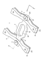
次に、本発明に係る鉄道車両用台車枠の一実施形態について、図面を参照しながら以下に説明する。図1は、鉄道車両用台車枠の実施形態を示した斜視図である。この鉄道車両用台車枠(以下、単に「台車枠」とする)1は、レール方向に沿って配置された2本の側梁2を左右に有し、枕木方向に沿って配置された横梁3に貫かれ、その貫通部分において側梁2と横梁3とが溶接によって接合されている。なお、図示するY軸方向がレール方向であり、X軸方向が枕木方向である。
Next, an embodiment of a bogie frame for a railway vehicle according to the present invention will be described below with reference to the drawings. FIG. 1 is a perspective view showing an embodiment of a bogie frame for a railway vehicle. This railcar bogie frame (hereinafter simply referred to as “trolley frame”) 1 has two
台車枠1は、2本の管材を使用していた従来のものとは異なり、横梁3が一つの部材で構成されている。横梁3は、厚さ寸法に比べて幅方向、つまり台車枠1におけるレール方向の寸法が大きく、その長手方向(図のX方向)に見た断面が扁平形状をしている。横梁3は、側梁2を貫通する左右の接合部31と、長円形状の貫通孔33を有する中間部32とから構成されている。接合部31は、断面が長円形状であって所定の幅を有している。中間部32は、接合部31よりも幅広であって、図1に示すように、レール方向に突き出すようにして形成されている。
Unlike the
図2は、横梁3の製作について示した斜視図である。横梁3は、上下方向に分割された構造であって、一対の横梁部材30A,30Bが鋼板からプレス成形され、それらが上下に重ねられ溶接されたものである。横梁部材30A,30Bは、横梁3の接合部31に相当する接合部分310と、中間部32に相当する中間部分320によって構成されている。中間部分320は、接合部分310よりも幅が広く、中央に長円形状の貫通孔に沿って縁部331が形成されている。接合部分310の縁部311はなだらかに折り曲げられた曲面であるのに対し、中間部分320の縁部321や縁部331は、ほぼ直交方向に折り曲げられた平面である。こうした一対の横梁部材30A,30Bは上下に重ね合わされ、その合わせ部分が溶接される。
FIG. 2 is a perspective view showing the production of the
次に図3は、側梁2を構成する側梁部材を示した斜視図である。側梁部材20は、鋼板をプレス成形したものである。側梁部材20は、両端にバネ帽を構成する幅広のバネ帽部21が形成され、両端のバネ帽部21の間に中間部22が形成されている。中間部22は、バネ帽部21よりも位置が低くなるように下方に傾斜する部分が形成されている。そして、中間部22は、バネ帽部21より幅方向の寸法が小さい分、横梁3が貫通しても剛性が保てるように高さ方向の寸法が大きく取られている。
Next, FIG. 3 is a perspective view showing a side beam member constituting the
側梁部材20は、断面がコの字形であって、下方の開口端に下プレート24(図4参照)が溶接される。後述するように側梁2が補助空気室となるため、側梁2を気密な空間にする仕切板23が内部に溶接される。また、側梁部材20の長手方向端部には、図1に示すように当板251が溶接され、バネ帽部21には、下プレートも含めてバネ帽を構成するため貫通孔が形成される。台車枠1は、こうして形成された側梁2と横梁3とによって構成され、図1に示すように、側梁2の中間部22に横梁3の接合部31が貫通し、溶接によって接合される。
The
鉄道車両の空気バネは、台車枠1に設けられた補助空気室と接続され、見かけの内部容積がその補助空気室の分だけ大きくなり、そうした補助空気室と空気バネとの間には絞り弁が設けられ、粘性減衰特性を発揮させるようにしている。本実施形態の台車枠1では、側梁2を貫通して突き出した横梁3の接合部31に空気バネを設置するための空気バネ座4が設けられている。このように、空気バネ座4が横梁3上にある場合、補助空気室を横梁3に構成すれば、空気バネを接続する点では容易である。しかし、台車枠1は、横梁3が一つの部材で構成されているため、内部を2室に分割しなければならず、その点で気密性を保った製作が困難になる。
The air spring of the railway vehicle is connected to an auxiliary air chamber provided in the
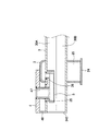
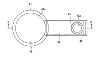
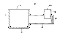
そこで、本実施形態では左右一対の側梁2をそれぞれ補助空気室25として構成することとした。そのためには横梁3から側梁2への流路が必要になるが、図4は、そうした空気バネと補助空気室との接続構造を示した図1のA−A断面図である。側梁2を貫通した横梁3内には、空気バネ座4に設置する空気ばねと側梁2内の補助空気室25とを接続する気密配管5が設けられている。ここで図5は、気密配管5の第1案を示した平面図であり、図6は、気密配管5の第1案を示した図5のB−B断面図である。
Therefore, in this embodiment, the pair of left and right side beams 2 are each configured as the
この第1案の気密配管5Aは、大きさの異なる3つの鋼管を接続し構成されたものである。上下方向に配置された最も径の大きい本管41に対し、横方向に開けられた横孔に横管42が差し込まれ、更にその横管42の先端部に開けられた縦孔に縦管43が上方を向いて差し込まれている。そして、本管41の下側と横管42の先端が塞ぎ板45,46によって閉じられ、本管41の開口部41aから縦管43の開口部43aまでが一本の流路になっている。それぞれの接合部は溶接によって一体に接合されている。なお、本管41、横管42および縦管43は、圧力配管用炭素鋼鋼管(STPG)が使用され、塞ぎ板45,46には溶接構造用圧延鋼材(SM)が使用されている。
The
横梁3は、一対の横梁部材30A,30Bを上下に合わせて溶接した後、その接合部31の端部に図1に示す長円形状の塞ぎ板342が溶接される。気密配管5(5A)は、その塞ぎ板342が溶接される前に横梁3内に入れられ、上側の横梁部材30Aに対して溶接される。横梁3の上面に嵌合孔35,36(図4参照)が形成され、そこには図5及び図6に示す本管41と縦管43の先端が嵌め込まれる。そして、嵌合した本管41と縦管43のそれぞれの周縁部に沿って横梁3の外側から溶接が行われ、気密配管5(5A)が横梁2内に固定される。その後に、前述した両端の開口部が塞ぎ板342によって塞がれ、横梁3内が気密になる。
The
このようにして図1に示す1本の横梁3が製作された後、側梁2の側部に形成された貫通孔を接合部31が貫通し、接合部の溶接によって略H形の台車枠1がつくられる。このとき、気密配管5(5A)は、本管41の開口部41aが側梁2の外側に位置し、縦管43の開口部43aが側梁2内に位置する。外側の開口部41aには、本管41内に図4に示すように案内管47が差し込まれ、本管41と案内管47とが気密配管5(5A)内の気密な状態を保つように溶接される。案内管47は、横梁3の上面から突き出し、その先端部には空気バネ座4が嵌め込まれ、溶接によって接合される。空気バネ座4の一部は側梁2に支持され、その反対側が受板48に支持される。
After the one
鉄道車両は、この空気バネ座4に空気バネが設置され、その空気バネの内部が気密配管5(5A)を介して側梁2内の補助空気室25と接続される。こうして主空気室となる空気バネに容積の大きな補助空気室25をつないだ状態で空気を封入することにより、空気バネの柔らかいバネ特性を得ることができ、走行中に車体に作用する振動を吸収して乗り心地を良くしている。空気バネと補助空気室25とを接続する流路の途中、具体的には案内管47内には不図示の固定絞りが設置され、それによって粘性減衰特性を発揮させた振動低減を実現している。
In the railway vehicle, an air spring is installed on the
以上、本実施形態の台車枠1によれば、プレス成形した一対の横梁部材30A,30Bによって横梁3を一つの部材としたため、構造の簡素化によってコストを低減させ、また、側梁2に対する接合部は、2本の横梁に比べて狭いスペースでの溶接作業がなくなり、側梁2内の気密性を保った溶接を容易かつ確実に行うことができる。そして、こうした横梁3上に空気バネを設置した場合、本実施形態では横梁3内に設けた気密配管5(5A)によって空気バネと側梁2内の補助空気室25とを接続するので、横梁3に補助空気室を構成して構造を複雑にする必要がなくなり、前記横梁3本来の効果を得ることができる。
As described above, according to the
また、図5及び図6に示した第1案の気密配管5Aは、3つの鋼管を接続した簡易な構成であるため、その製作が容易であり、コストも安価なものとすることができる。そして、この気密配管5(5A)を使用した流路の構造は、一対の横梁部材30A,30Bを溶接した後の横梁3に対してその内部に容易に取り付けることができ、簡易な構成であるため気密性を確保することもできる。また、気密配管5(5A)が横梁3内にあるため、側梁2に対する横梁3の位置を変更してもその影響を受けない。そして、気密配管5(5A)を使用した内部流路のため、鉄道車両の走行中に飛び石などによって破損するおそれもなく、メンテナンスの手間も省ける。
Further, since the first
次に、図7は、気密配管5の第2案を示した図6に対応した断面図である。第2案の気密配管5Bは、第1案では3つの鋼管を使用したのに対し、2つの鋼管によって構成されている。気密配管5Bは、上下方向に配置された本管51に対し、横方向に開けられた横孔に曲げ管52が差し込まれ、本管51の下側が塞ぎ板53によって閉じられている。それぞれの接合部は溶接によって一体に接合され、本管51の開口部51aから曲げ管52の開口部52aまでが流路として構成されている。
Next, FIG. 7 is a cross-sectional view corresponding to FIG. 6 showing the second plan of the airtight pipe 5. The
気密配管5Bは、前述した第1案と同様に、横梁3内において上側の横梁部材30Aに溶接される。すなわち、横梁3の上面に形成された嵌合孔35,36に本管51と曲げ管52の先端が嵌め込まれ、本管51と曲げ管52のそれぞれの周縁部に沿って溶接が行われる。気密配管5(5B)を備えた横梁3は、側梁2の側部に形成された貫通孔に通され、接合部の溶接接合によって図1に示すような略H形の台車枠1が構成される。空気バネ座4に設置された空気バネは、その内部が気密配管5(5B)を介して側梁2内の補助空気室25と連結され、容積を大きくすることにより柔らかいバネ特性を得ることができる。
The
こうした気密配管5Bを備えた台車枠1は、気密配管5Bが第1案よりも部品点数を少なくすることができる。また、前記第1案の場合と同様の効果を奏する。すなわち、横梁3上に設置した空気バネを、その横梁3内に設けた気密配管5Bによって側梁2の補助空気室25と連通させることで、構造を複雑にすることなく横梁3本来の効果を得ることができる。また、簡易な構成で溶接箇所も少ないため気密性を高めることもできるなどの効果を奏する。
In the
以上、本発明に係る鉄道車両用台車枠について実施形態を説明したが、本発明はこれに限定されることなく、その趣旨を逸脱しない範囲で様々な変更が可能である。
例えば、前記実施形態では、気密配管5の第1案及び第2案として鋼管によって構成したものを説明したが、その他にも鍛造によって製作したものや、削り出しによって加工したものであってもよい。
また、前記実施形態では気密配管5を上側の横梁部材30Aに接合したものを示して説明したが、例えば、第1案の気密配管5Aにおいて、その縦管43を上下逆転させて下側の横梁部材30Bに開けた嵌合孔に差し込んで溶接するようにしてもよい。
また、前記実施形態では、横梁3が側梁2を貫通する構造の台車枠1を示したが、例えば横梁3が側梁2の上に重ねた台車枠であってもよい。その際には、前述したように縦管43下側に設けた気密配管が使用される。
As mentioned above, although embodiment was described about the bogie frame for rail vehicles which concerns on this invention, this invention is not limited to this, A various change is possible in the range which does not deviate from the meaning.
For example, in the said embodiment, what was comprised by the steel pipe as the 1st proposal and 2nd proposal of the airtight piping 5 was demonstrated, but what was manufactured by forge, and what was processed by cutting out may be used. .
In the above embodiment, the airtight pipe 5 joined to the upper
Moreover, in the said embodiment, although the
1 鉄道車両用台車枠
2 側梁
3 横梁
5(5A) 気密配管
30A,30B 横梁部材
35,36 嵌合孔
41 本管
42 横管
43 縦管
45,46 塞ぎ板
DESCRIPTION OF
Claims (4)
前記横梁には、上面の前記空気バネの中心に相当する位置と、上面又は下面の前記側梁と重なる位置とに2つの嵌合孔が形成され、内部に前記2つの嵌合孔を接続する気密配管が設けられたものであることを特徴とする鉄道車両用台車枠。 A railway in which one side beam arranged along the direction of a sleeper crosses and is joined to two side beams arranged along the rail direction, and an air spring is installed on the side beam. Vehicle carriage frame,
Two fitting holes are formed in the horizontal beam at a position corresponding to the center of the air spring on the upper surface and a position overlapping the side beam on the upper surface or the lower surface, and the two fitting holes are connected inside. A bogie frame for a railway vehicle, characterized in that an airtight pipe is provided.
前記2つの嵌合孔は前記横梁の上面に形成され、前記気密配管は前記横梁の上側に接合されたものであることを特徴とする鉄道車両用台車枠。 In the bogie frame for railway vehicles according to claim 1,
The bogie frame for a railway vehicle, wherein the two fitting holes are formed on an upper surface of the transverse beam, and the airtight pipe is joined to the upper side of the transverse beam.
前記気密配管は、複数の管部材を接合して一の流路を形成したものであることを特徴とする鉄道車両用台車枠。 In the bogie frame for a railway vehicle according to claim 1 or claim 2,
The bogie frame for a railway vehicle, wherein the airtight pipe is formed by joining a plurality of pipe members to form one flow path.
前記横梁は、上下方向に2分割した一対の横梁部材がプレス成形によって鋼板から形成され、その横梁部材同士が溶接によって接合されて一体になったものであることを特徴とする鉄道車両用台車枠。 In the bogie frame for railway vehicles according to any one of claims 1 to 3,
The transverse beam is a bogie frame for a railway vehicle, wherein a pair of transverse beam members divided into two in the vertical direction are formed from a steel plate by press forming, and the transverse beam members are joined together by welding. .
Priority Applications (1)
| Application Number | Priority Date | Filing Date | Title |
|---|---|---|---|
| JP2011039953A JP5642588B2 (en) | 2011-02-25 | 2011-02-25 | Bogie frame for railway vehicles |
Applications Claiming Priority (1)
| Application Number | Priority Date | Filing Date | Title |
|---|---|---|---|
| JP2011039953A JP5642588B2 (en) | 2011-02-25 | 2011-02-25 | Bogie frame for railway vehicles |
Publications (2)
| Publication Number | Publication Date |
|---|---|
| JP2012176653A true JP2012176653A (en) | 2012-09-13 |
| JP5642588B2 JP5642588B2 (en) | 2014-12-17 |
Family
ID=46978832
Family Applications (1)
| Application Number | Title | Priority Date | Filing Date |
|---|---|---|---|
| JP2011039953A Active JP5642588B2 (en) | 2011-02-25 | 2011-02-25 | Bogie frame for railway vehicles |
Country Status (1)
| Country | Link |
|---|---|
| JP (1) | JP5642588B2 (en) |
Cited By (5)
| Publication number | Priority date | Publication date | Assignee | Title |
|---|---|---|---|---|
| CN104442892A (en) * | 2014-11-26 | 2015-03-25 | 南车南京浦镇车辆有限公司 | Production technology of sleeper beam with additional air chamber |
| CN104554322A (en) * | 2014-12-23 | 2015-04-29 | 长春轨道客车股份有限公司 | Frame of bogie for A-type broad-gauge metro vehicle |
| CN104691569A (en) * | 2013-12-05 | 2015-06-10 | 南车青岛四方机车车辆股份有限公司 | Steering frame and framework thereof |
| CN106740963A (en) * | 2017-01-23 | 2017-05-31 | 中车长江车辆有限公司 | Railway red ball bogie framework |
| WO2023046139A1 (en) * | 2021-09-26 | 2023-03-30 | 中车青岛四方机车车辆股份有限公司 | Frame, bogie, and rail vehicle |
Citations (4)
| Publication number | Priority date | Publication date | Assignee | Title |
|---|---|---|---|---|
| JPS5788939A (en) * | 1980-11-21 | 1982-06-03 | Kawasaki Heavy Ind Ltd | Truck frame |
| JPS6040913Y2 (en) * | 1980-06-30 | 1985-12-11 | 住友金属工業株式会社 | air spring |
| JPH1120693A (en) * | 1997-07-04 | 1999-01-26 | Hitachi Ltd | Truck frame for railway rolling stock |
| JPH11227602A (en) * | 1998-02-13 | 1999-08-24 | Sumitomo Metal Ind Ltd | Truck frame for rolling stock |
-
2011
- 2011-02-25 JP JP2011039953A patent/JP5642588B2/en active Active
Patent Citations (4)
| Publication number | Priority date | Publication date | Assignee | Title |
|---|---|---|---|---|
| JPS6040913Y2 (en) * | 1980-06-30 | 1985-12-11 | 住友金属工業株式会社 | air spring |
| JPS5788939A (en) * | 1980-11-21 | 1982-06-03 | Kawasaki Heavy Ind Ltd | Truck frame |
| JPH1120693A (en) * | 1997-07-04 | 1999-01-26 | Hitachi Ltd | Truck frame for railway rolling stock |
| JPH11227602A (en) * | 1998-02-13 | 1999-08-24 | Sumitomo Metal Ind Ltd | Truck frame for rolling stock |
Cited By (5)
| Publication number | Priority date | Publication date | Assignee | Title |
|---|---|---|---|---|
| CN104691569A (en) * | 2013-12-05 | 2015-06-10 | 南车青岛四方机车车辆股份有限公司 | Steering frame and framework thereof |
| CN104442892A (en) * | 2014-11-26 | 2015-03-25 | 南车南京浦镇车辆有限公司 | Production technology of sleeper beam with additional air chamber |
| CN104554322A (en) * | 2014-12-23 | 2015-04-29 | 长春轨道客车股份有限公司 | Frame of bogie for A-type broad-gauge metro vehicle |
| CN106740963A (en) * | 2017-01-23 | 2017-05-31 | 中车长江车辆有限公司 | Railway red ball bogie framework |
| WO2023046139A1 (en) * | 2021-09-26 | 2023-03-30 | 中车青岛四方机车车辆股份有限公司 | Frame, bogie, and rail vehicle |
Also Published As
| Publication number | Publication date |
|---|---|
| JP5642588B2 (en) | 2014-12-17 |
Similar Documents
| Publication | Publication Date | Title |
|---|---|---|
| WO2011099179A1 (en) | Bogie frame for railroad vehicle | |
| JP5642588B2 (en) | Bogie frame for railway vehicles | |
| JP5046782B2 (en) | Vehicle superstructure | |
| JP4556836B2 (en) | Railcar bogie | |
| CN105026189B (en) | Torque beam, moment of torsion beam assembly and torque beam suspension device | |
| WO2014027440A1 (en) | Truck frame for railroad vehicle | |
| JP4356540B2 (en) | Railcar bogie frame and railcar bogie | |
| JP5710376B2 (en) | Railway vehicle | |
| JP2010247694A (en) | Torsion beam | |
| JP6647907B2 (en) | Railcar structure | |
| CN103003099A (en) | Vehicle seat | |
| US11479275B2 (en) | Bolster beam of railcar bogie | |
| US9623883B2 (en) | Railcar truck | |
| JP2011148400A (en) | Truck frame for railroad vehicle | |
| JP6073280B2 (en) | Body superstructure | |
| WO2018155139A1 (en) | Bogie frame for railway car and bogie provided with same | |
| CN204641769U (en) | Central sill, central sill sleeper beam combination unit and railway truck | |
| JP6053592B2 (en) | Railcar side structure | |
| JP2020117076A (en) | Joint structure of vehicle panel | |
| JP2014037212A (en) | Railway vehicle truck |
Legal Events
| Date | Code | Title | Description |
|---|---|---|---|
| A621 | Written request for application examination |
Free format text: JAPANESE INTERMEDIATE CODE: A621 Effective date: 20140113 |
|
| A977 | Report on retrieval |
Free format text: JAPANESE INTERMEDIATE CODE: A971007 Effective date: 20141016 |
|
| TRDD | Decision of grant or rejection written | ||
| A01 | Written decision to grant a patent or to grant a registration (utility model) |
Free format text: JAPANESE INTERMEDIATE CODE: A01 Effective date: 20141028 |
|
| A61 | First payment of annual fees (during grant procedure) |
Free format text: JAPANESE INTERMEDIATE CODE: A61 Effective date: 20141029 |
|
| R150 | Certificate of patent or registration of utility model |
Ref document number: 5642588 Country of ref document: JP Free format text: JAPANESE INTERMEDIATE CODE: R150 |
|
| R250 | Receipt of annual fees |
Free format text: JAPANESE INTERMEDIATE CODE: R250 |
|
| R250 | Receipt of annual fees |
Free format text: JAPANESE INTERMEDIATE CODE: R250 |
|
| R250 | Receipt of annual fees |
Free format text: JAPANESE INTERMEDIATE CODE: R250 |
|
| R250 | Receipt of annual fees |
Free format text: JAPANESE INTERMEDIATE CODE: R250 |
|
| R250 | Receipt of annual fees |
Free format text: JAPANESE INTERMEDIATE CODE: R250 |
|
| R250 | Receipt of annual fees |
Free format text: JAPANESE INTERMEDIATE CODE: R250 |
|
| R250 | Receipt of annual fees |
Free format text: JAPANESE INTERMEDIATE CODE: R250 |