JP2012176652A - Vehicle and vehicle control method - Google Patents
Vehicle and vehicle control method Download PDFInfo
- Publication number
- JP2012176652A JP2012176652A JP2011039931A JP2011039931A JP2012176652A JP 2012176652 A JP2012176652 A JP 2012176652A JP 2011039931 A JP2011039931 A JP 2011039931A JP 2011039931 A JP2011039931 A JP 2011039931A JP 2012176652 A JP2012176652 A JP 2012176652A
- Authority
- JP
- Japan
- Prior art keywords
- internal combustion
- vehicle
- combustion engine
- engine
- ignition timing
- Prior art date
- Legal status (The legal status is an assumption and is not a legal conclusion. Google has not performed a legal analysis and makes no representation as to the accuracy of the status listed.)
- Granted
Links
Images


Classifications
-
- B—PERFORMING OPERATIONS; TRANSPORTING
- B60—VEHICLES IN GENERAL
- B60W—CONJOINT CONTROL OF VEHICLE SUB-UNITS OF DIFFERENT TYPE OR DIFFERENT FUNCTION; CONTROL SYSTEMS SPECIALLY ADAPTED FOR HYBRID VEHICLES; ROAD VEHICLE DRIVE CONTROL SYSTEMS FOR PURPOSES NOT RELATED TO THE CONTROL OF A PARTICULAR SUB-UNIT
- B60W20/00—Control systems specially adapted for hybrid vehicles
- B60W20/40—Controlling the engagement or disengagement of prime movers, e.g. for transition between prime movers
-
- B—PERFORMING OPERATIONS; TRANSPORTING
- B60—VEHICLES IN GENERAL
- B60K—ARRANGEMENT OR MOUNTING OF PROPULSION UNITS OR OF TRANSMISSIONS IN VEHICLES; ARRANGEMENT OR MOUNTING OF PLURAL DIVERSE PRIME-MOVERS IN VEHICLES; AUXILIARY DRIVES FOR VEHICLES; INSTRUMENTATION OR DASHBOARDS FOR VEHICLES; ARRANGEMENTS IN CONNECTION WITH COOLING, AIR INTAKE, GAS EXHAUST OR FUEL SUPPLY OF PROPULSION UNITS IN VEHICLES
- B60K6/00—Arrangement or mounting of plural diverse prime-movers for mutual or common propulsion, e.g. hybrid propulsion systems comprising electric motors and internal combustion engines ; Control systems therefor, i.e. systems controlling two or more prime movers, or controlling one of these prime movers and any of the transmission, drive or drive units Informative references: mechanical gearings with secondary electric drive F16H3/72; arrangements for handling mechanical energy structurally associated with the dynamo-electric machine H02K7/00; machines comprising structurally interrelated motor and generator parts H02K51/00; dynamo-electric machines not otherwise provided for in H02K see H02K99/00
- B60K6/20—Arrangement or mounting of plural diverse prime-movers for mutual or common propulsion, e.g. hybrid propulsion systems comprising electric motors and internal combustion engines ; Control systems therefor, i.e. systems controlling two or more prime movers, or controlling one of these prime movers and any of the transmission, drive or drive units Informative references: mechanical gearings with secondary electric drive F16H3/72; arrangements for handling mechanical energy structurally associated with the dynamo-electric machine H02K7/00; machines comprising structurally interrelated motor and generator parts H02K51/00; dynamo-electric machines not otherwise provided for in H02K see H02K99/00 the prime-movers consisting of electric motors and internal combustion engines, e.g. HEVs
- B60K6/42—Arrangement or mounting of plural diverse prime-movers for mutual or common propulsion, e.g. hybrid propulsion systems comprising electric motors and internal combustion engines ; Control systems therefor, i.e. systems controlling two or more prime movers, or controlling one of these prime movers and any of the transmission, drive or drive units Informative references: mechanical gearings with secondary electric drive F16H3/72; arrangements for handling mechanical energy structurally associated with the dynamo-electric machine H02K7/00; machines comprising structurally interrelated motor and generator parts H02K51/00; dynamo-electric machines not otherwise provided for in H02K see H02K99/00 the prime-movers consisting of electric motors and internal combustion engines, e.g. HEVs characterised by the architecture of the hybrid electric vehicle
- B60K6/44—Series-parallel type
- B60K6/445—Differential gearing distribution type
-
- B—PERFORMING OPERATIONS; TRANSPORTING
- B60—VEHICLES IN GENERAL
- B60W—CONJOINT CONTROL OF VEHICLE SUB-UNITS OF DIFFERENT TYPE OR DIFFERENT FUNCTION; CONTROL SYSTEMS SPECIALLY ADAPTED FOR HYBRID VEHICLES; ROAD VEHICLE DRIVE CONTROL SYSTEMS FOR PURPOSES NOT RELATED TO THE CONTROL OF A PARTICULAR SUB-UNIT
- B60W10/00—Conjoint control of vehicle sub-units of different type or different function
- B60W10/04—Conjoint control of vehicle sub-units of different type or different function including control of propulsion units
- B60W10/06—Conjoint control of vehicle sub-units of different type or different function including control of propulsion units including control of combustion engines
-
- B—PERFORMING OPERATIONS; TRANSPORTING
- B60—VEHICLES IN GENERAL
- B60W—CONJOINT CONTROL OF VEHICLE SUB-UNITS OF DIFFERENT TYPE OR DIFFERENT FUNCTION; CONTROL SYSTEMS SPECIALLY ADAPTED FOR HYBRID VEHICLES; ROAD VEHICLE DRIVE CONTROL SYSTEMS FOR PURPOSES NOT RELATED TO THE CONTROL OF A PARTICULAR SUB-UNIT
- B60W10/00—Conjoint control of vehicle sub-units of different type or different function
- B60W10/04—Conjoint control of vehicle sub-units of different type or different function including control of propulsion units
- B60W10/08—Conjoint control of vehicle sub-units of different type or different function including control of propulsion units including control of electric propulsion units, e.g. motors or generators
-
- B—PERFORMING OPERATIONS; TRANSPORTING
- B60—VEHICLES IN GENERAL
- B60W—CONJOINT CONTROL OF VEHICLE SUB-UNITS OF DIFFERENT TYPE OR DIFFERENT FUNCTION; CONTROL SYSTEMS SPECIALLY ADAPTED FOR HYBRID VEHICLES; ROAD VEHICLE DRIVE CONTROL SYSTEMS FOR PURPOSES NOT RELATED TO THE CONTROL OF A PARTICULAR SUB-UNIT
- B60W20/00—Control systems specially adapted for hybrid vehicles
-
- B—PERFORMING OPERATIONS; TRANSPORTING
- B60—VEHICLES IN GENERAL
- B60W—CONJOINT CONTROL OF VEHICLE SUB-UNITS OF DIFFERENT TYPE OR DIFFERENT FUNCTION; CONTROL SYSTEMS SPECIALLY ADAPTED FOR HYBRID VEHICLES; ROAD VEHICLE DRIVE CONTROL SYSTEMS FOR PURPOSES NOT RELATED TO THE CONTROL OF A PARTICULAR SUB-UNIT
- B60W40/00—Estimation or calculation of non-directly measurable driving parameters for road vehicle drive control systems not related to the control of a particular sub unit, e.g. by using mathematical models
- B60W40/10—Estimation or calculation of non-directly measurable driving parameters for road vehicle drive control systems not related to the control of a particular sub unit, e.g. by using mathematical models related to vehicle motion
- B60W40/105—Speed
-
- F—MECHANICAL ENGINEERING; LIGHTING; HEATING; WEAPONS; BLASTING
- F02—COMBUSTION ENGINES; HOT-GAS OR COMBUSTION-PRODUCT ENGINE PLANTS
- F02P—IGNITION, OTHER THAN COMPRESSION IGNITION, FOR INTERNAL-COMBUSTION ENGINES; TESTING OF IGNITION TIMING IN COMPRESSION-IGNITION ENGINES
- F02P5/00—Advancing or retarding ignition; Control therefor
- F02P5/04—Advancing or retarding ignition; Control therefor automatically, as a function of the working conditions of the engine or vehicle or of the atmospheric conditions
- F02P5/145—Advancing or retarding ignition; Control therefor automatically, as a function of the working conditions of the engine or vehicle or of the atmospheric conditions using electrical means
- F02P5/15—Digital data processing
- F02P5/1502—Digital data processing using one central computing unit
- F02P5/1506—Digital data processing using one central computing unit with particular means during starting
-
- B—PERFORMING OPERATIONS; TRANSPORTING
- B60—VEHICLES IN GENERAL
- B60W—CONJOINT CONTROL OF VEHICLE SUB-UNITS OF DIFFERENT TYPE OR DIFFERENT FUNCTION; CONTROL SYSTEMS SPECIALLY ADAPTED FOR HYBRID VEHICLES; ROAD VEHICLE DRIVE CONTROL SYSTEMS FOR PURPOSES NOT RELATED TO THE CONTROL OF A PARTICULAR SUB-UNIT
- B60W20/00—Control systems specially adapted for hybrid vehicles
- B60W20/20—Control strategies involving selection of hybrid configuration, e.g. selection between series or parallel configuration
-
- B—PERFORMING OPERATIONS; TRANSPORTING
- B60—VEHICLES IN GENERAL
- B60W—CONJOINT CONTROL OF VEHICLE SUB-UNITS OF DIFFERENT TYPE OR DIFFERENT FUNCTION; CONTROL SYSTEMS SPECIALLY ADAPTED FOR HYBRID VEHICLES; ROAD VEHICLE DRIVE CONTROL SYSTEMS FOR PURPOSES NOT RELATED TO THE CONTROL OF A PARTICULAR SUB-UNIT
- B60W2510/00—Input parameters relating to a particular sub-units
- B60W2510/06—Combustion engines, Gas turbines
- B60W2510/0614—Position of fuel or air injector
- B60W2510/0628—Inlet air flow rate
-
- B—PERFORMING OPERATIONS; TRANSPORTING
- B60—VEHICLES IN GENERAL
- B60W—CONJOINT CONTROL OF VEHICLE SUB-UNITS OF DIFFERENT TYPE OR DIFFERENT FUNCTION; CONTROL SYSTEMS SPECIALLY ADAPTED FOR HYBRID VEHICLES; ROAD VEHICLE DRIVE CONTROL SYSTEMS FOR PURPOSES NOT RELATED TO THE CONTROL OF A PARTICULAR SUB-UNIT
- B60W2510/00—Input parameters relating to a particular sub-units
- B60W2510/06—Combustion engines, Gas turbines
- B60W2510/0676—Engine temperature
-
- B—PERFORMING OPERATIONS; TRANSPORTING
- B60—VEHICLES IN GENERAL
- B60W—CONJOINT CONTROL OF VEHICLE SUB-UNITS OF DIFFERENT TYPE OR DIFFERENT FUNCTION; CONTROL SYSTEMS SPECIALLY ADAPTED FOR HYBRID VEHICLES; ROAD VEHICLE DRIVE CONTROL SYSTEMS FOR PURPOSES NOT RELATED TO THE CONTROL OF A PARTICULAR SUB-UNIT
- B60W2510/00—Input parameters relating to a particular sub-units
- B60W2510/24—Energy storage means
- B60W2510/242—Energy storage means for electrical energy
- B60W2510/244—Charge state
-
- B—PERFORMING OPERATIONS; TRANSPORTING
- B60—VEHICLES IN GENERAL
- B60W—CONJOINT CONTROL OF VEHICLE SUB-UNITS OF DIFFERENT TYPE OR DIFFERENT FUNCTION; CONTROL SYSTEMS SPECIALLY ADAPTED FOR HYBRID VEHICLES; ROAD VEHICLE DRIVE CONTROL SYSTEMS FOR PURPOSES NOT RELATED TO THE CONTROL OF A PARTICULAR SUB-UNIT
- B60W2520/00—Input parameters relating to overall vehicle dynamics
- B60W2520/10—Longitudinal speed
-
- B—PERFORMING OPERATIONS; TRANSPORTING
- B60—VEHICLES IN GENERAL
- B60W—CONJOINT CONTROL OF VEHICLE SUB-UNITS OF DIFFERENT TYPE OR DIFFERENT FUNCTION; CONTROL SYSTEMS SPECIALLY ADAPTED FOR HYBRID VEHICLES; ROAD VEHICLE DRIVE CONTROL SYSTEMS FOR PURPOSES NOT RELATED TO THE CONTROL OF A PARTICULAR SUB-UNIT
- B60W2555/00—Input parameters relating to exterior conditions, not covered by groups B60W2552/00, B60W2554/00
- B60W2555/20—Ambient conditions, e.g. wind or rain
-
- B—PERFORMING OPERATIONS; TRANSPORTING
- B60—VEHICLES IN GENERAL
- B60W—CONJOINT CONTROL OF VEHICLE SUB-UNITS OF DIFFERENT TYPE OR DIFFERENT FUNCTION; CONTROL SYSTEMS SPECIALLY ADAPTED FOR HYBRID VEHICLES; ROAD VEHICLE DRIVE CONTROL SYSTEMS FOR PURPOSES NOT RELATED TO THE CONTROL OF A PARTICULAR SUB-UNIT
- B60W30/00—Purposes of road vehicle drive control systems not related to the control of a particular sub-unit, e.g. of systems using conjoint control of vehicle sub-units, or advanced driver assistance systems for ensuring comfort, stability and safety or drive control systems for propelling or retarding the vehicle
- B60W30/18—Propelling the vehicle
- B60W30/192—Mitigating problems related to power-up or power-down of the driveline, e.g. start-up of a cold engine
-
- F—MECHANICAL ENGINEERING; LIGHTING; HEATING; WEAPONS; BLASTING
- F02—COMBUSTION ENGINES; HOT-GAS OR COMBUSTION-PRODUCT ENGINE PLANTS
- F02D—CONTROLLING COMBUSTION ENGINES
- F02D2200/00—Input parameters for engine control
- F02D2200/02—Input parameters for engine control the parameters being related to the engine
- F02D2200/021—Engine temperature
-
- F—MECHANICAL ENGINEERING; LIGHTING; HEATING; WEAPONS; BLASTING
- F02—COMBUSTION ENGINES; HOT-GAS OR COMBUSTION-PRODUCT ENGINE PLANTS
- F02N—STARTING OF COMBUSTION ENGINES; STARTING AIDS FOR SUCH ENGINES, NOT OTHERWISE PROVIDED FOR
- F02N11/00—Starting of engines by means of electric motors
- F02N11/04—Starting of engines by means of electric motors the motors being associated with current generators
-
- F—MECHANICAL ENGINEERING; LIGHTING; HEATING; WEAPONS; BLASTING
- F02—COMBUSTION ENGINES; HOT-GAS OR COMBUSTION-PRODUCT ENGINE PLANTS
- F02N—STARTING OF COMBUSTION ENGINES; STARTING AIDS FOR SUCH ENGINES, NOT OTHERWISE PROVIDED FOR
- F02N2200/00—Parameters used for control of starting apparatus
- F02N2200/10—Parameters used for control of starting apparatus said parameters being related to driver demands or status
- F02N2200/101—Accelerator pedal position
-
- Y—GENERAL TAGGING OF NEW TECHNOLOGICAL DEVELOPMENTS; GENERAL TAGGING OF CROSS-SECTIONAL TECHNOLOGIES SPANNING OVER SEVERAL SECTIONS OF THE IPC; TECHNICAL SUBJECTS COVERED BY FORMER USPC CROSS-REFERENCE ART COLLECTIONS [XRACs] AND DIGESTS
- Y02—TECHNOLOGIES OR APPLICATIONS FOR MITIGATION OR ADAPTATION AGAINST CLIMATE CHANGE
- Y02T—CLIMATE CHANGE MITIGATION TECHNOLOGIES RELATED TO TRANSPORTATION
- Y02T10/00—Road transport of goods or passengers
- Y02T10/10—Internal combustion engine [ICE] based vehicles
- Y02T10/40—Engine management systems
-
- Y—GENERAL TAGGING OF NEW TECHNOLOGICAL DEVELOPMENTS; GENERAL TAGGING OF CROSS-SECTIONAL TECHNOLOGIES SPANNING OVER SEVERAL SECTIONS OF THE IPC; TECHNICAL SUBJECTS COVERED BY FORMER USPC CROSS-REFERENCE ART COLLECTIONS [XRACs] AND DIGESTS
- Y02—TECHNOLOGIES OR APPLICATIONS FOR MITIGATION OR ADAPTATION AGAINST CLIMATE CHANGE
- Y02T—CLIMATE CHANGE MITIGATION TECHNOLOGIES RELATED TO TRANSPORTATION
- Y02T10/00—Road transport of goods or passengers
- Y02T10/60—Other road transportation technologies with climate change mitigation effect
- Y02T10/62—Hybrid vehicles
Abstract
Description
本発明は、ハイブリッド車両に搭載された内燃機関の始動制御に関する。 The present invention relates to start control of an internal combustion engine mounted on a hybrid vehicle.
回転電機と内燃機関を搭載したハイブリッド車両においては、車両の走行中に内燃機関を始動させる場合がある。たとえば、特開2007−182179号公報(特許文献1)には、ハイブリッド車両の走行中に内燃機関を始動させる場合に、車速が低くなるほど内燃機関の始動時の点火時期を遅角させる技術が開示されている。 In a hybrid vehicle equipped with a rotating electrical machine and an internal combustion engine, the internal combustion engine may be started while the vehicle is traveling. For example, Japanese Unexamined Patent Application Publication No. 2007-182179 (Patent Document 1) discloses a technique for retarding the ignition timing at the start of the internal combustion engine as the vehicle speed decreases when the internal combustion engine is started while the hybrid vehicle is running. Has been.
ところで、ハイブリッド車両においては、回転電機を用いて車両を走行させる制御と回転電機と内燃機関とを用いて車両を走行させる制御とのうちのいずれかが実行される。これらの制御のうちのいずれを優先するかによって、内燃機関の始動時に適切な点火時期を決定する必要がある。これは、いずれの制御を優先して実行するかによって内燃機関の始動時における状態が異なる場合があるためである。上述した公報に開示された車両の制御装置においては、このような問題について考慮されておらず、点火時期の決定について改善の余地がある。 By the way, in the hybrid vehicle, one of control for running the vehicle using the rotating electrical machine and control for running the vehicle using the rotating electrical machine and the internal combustion engine is executed. Depending on which of these controls is prioritized, it is necessary to determine an appropriate ignition timing when starting the internal combustion engine. This is because the state at the start of the internal combustion engine may differ depending on which control is executed with priority. The vehicle control device disclosed in the above-mentioned publication does not consider such a problem, and there is room for improvement in determining the ignition timing.
本発明は、上述した課題を解決するためになされたものであって、その目的は、ハイブリッド車両に搭載された内燃機関の始動時に適切な点火時期を決定する車両および車両用制御方法を提供することである。 The present invention has been made to solve the above-described problems, and an object of the present invention is to provide a vehicle and a vehicle control method for determining an appropriate ignition timing when starting an internal combustion engine mounted on a hybrid vehicle. That is.
この発明のある局面に係る車両は、内燃機関と、車両に駆動力を発生させるための回転電機と、車両の状態に応じて内燃機関を制御するための制御部とを含む。制御部は、駆動力の要求に応じて内燃機関を始動させる場合には、第1モードが選択されているときの内燃機関の点火時期が、第2モードが選択されているときの点火時期よりも遅くなるように内燃機関を制御する。第1モードは、第2モードよりも、内燃機関を停止させた状態で回転電機によって車両が走行されやすいモードである。 A vehicle according to an aspect of the present invention includes an internal combustion engine, a rotating electrical machine for generating a driving force in the vehicle, and a control unit for controlling the internal combustion engine in accordance with the state of the vehicle. When starting the internal combustion engine in response to a request for driving force, the control unit determines that the ignition timing of the internal combustion engine when the first mode is selected is higher than the ignition timing when the second mode is selected. The internal combustion engine is controlled so as to be slower. The first mode is a mode in which the vehicle is more easily driven by the rotating electrical machine with the internal combustion engine stopped than in the second mode.
好ましくは、制御部は、車両のシステムが起動してから最初に駆動力の要求に応じて内燃機関を始動させる場合には、第1モードが選択されているときの点火時期が、第2モードが選択されているときの点火時期よりも遅くなるように内燃機関を制御する。 Preferably, when starting the internal combustion engine in response to a request for driving force for the first time after starting the vehicle system, the control unit determines that the ignition timing when the first mode is selected is the second mode. The internal combustion engine is controlled to be later than the ignition timing when is selected.
さらに好ましくは、制御部は、システムが起動してから停止するまでの間における最初の内燃機関の始動時の点火時期と、2回目以降の内燃機関の始動時の点火時期とが異なるように内燃機関を制御する。 More preferably, the control unit is configured so that the ignition timing at the start of the first internal combustion engine between the start of the system and the stop thereof is different from the ignition timing at the start of the second and subsequent internal combustion engines. Control the engine.
さらに好ましくは、制御部は、システムが起動してから停止するまでの間における2回目以降の内燃機関の始動時の点火時期が、最初の内燃機関の始動時の点火時期よりも遅くなるように内燃機関を制御する。 More preferably, the control unit sets the ignition timing at the start of the internal combustion engine for the second and subsequent times from when the system is started to when it is stopped to be later than the ignition timing at the start of the first internal combustion engine. Control the internal combustion engine.
さらに好ましくは、制御部は、駆動力の要求に応じて内燃機関を始動させるときの点火時期と、駆動力以外の要求に応じて内燃機関を始動させるときの点火時期とが異なるように内燃機関を制御する。 More preferably, the control unit is configured so that the ignition timing when starting the internal combustion engine in response to a request for driving force is different from the ignition timing when starting the internal combustion engine in response to a request other than the driving force. To control.
さらに好ましくは、制御部は、第2モードが選択されている場合には、駆動力以外の要求に応じて内燃機関を始動させるときの点火時期が、駆動力の要求に応じて内燃機関を始動させるときの点火時期よりも遅くなるように内燃機関を制御する。 More preferably, when the second mode is selected, the control unit starts the internal combustion engine in response to the ignition timing when starting the internal combustion engine in response to a request other than the driving force. The internal combustion engine is controlled so as to be later than the ignition timing at the time of ignition.
さらに好ましくは、車両は、回転電機に電力を供給するための蓄電装置をさらに含む。制御部は、第1モードが選択されている場合には、蓄電装置の残容量が第1しきい値よりも低下した場合に、内燃機関が始動するように内燃機関を制御し、第2モードが選択されている場合には、残容量が第2しきい値よりも高い状態を維持するように車両を制御する。 More preferably, the vehicle further includes a power storage device for supplying electric power to the rotating electrical machine. When the first mode is selected, the control unit controls the internal combustion engine so that the internal combustion engine starts when the remaining capacity of the power storage device falls below the first threshold, and the second mode Is selected, the vehicle is controlled so that the remaining capacity is maintained higher than the second threshold value.
さらに好ましくは、回転電機は、車両の駆動軸を回転させて車両を走行させるための第1回転電機である。車両は、第2回転電機と、駆動軸、内燃機関の出力軸および第2回転電機の回転軸の三要素の各々を機械的に連結し、三要素のうちのいずれか一つを反力要素とすることによって、他の2つの要素間での動力伝達が可能な動力伝達装置とをさらに含む。 More preferably, the rotating electrical machine is a first rotating electrical machine for driving the vehicle by rotating a drive shaft of the vehicle. The vehicle mechanically connects each of the three elements of the second rotating electrical machine, the drive shaft, the output shaft of the internal combustion engine, and the rotating shaft of the second rotating electrical machine, and any one of the three elements is a reaction force element. And a power transmission device capable of transmitting power between the other two elements.
この発明の他の局面に係る車両用制御方法は、内燃機関と、車両に駆動力を発生させるための回転電機と、回転電機に電力を供給するための蓄電装置とを搭載した車両に用いられる車両用制御方法である。この車両用制御方法は、駆動力の要求を検出するステップと、駆動力の要求に応じて内燃機関を始動させる場合に、第1モードが選択されているときの内燃機関の点火時期が、第2モードが選択されている場合の点火時期よりも遅くなるように内燃機関を制御するステップとを含む。第1モードは、第2モードよりも、内燃機関を停止させた状態で回転電機によって車両が走行されやすいモードである。 A vehicle control method according to another aspect of the present invention is used for a vehicle equipped with an internal combustion engine, a rotating electrical machine for generating a driving force for the vehicle, and a power storage device for supplying electric power to the rotating electrical machine. This is a control method for a vehicle. The vehicle control method includes a step of detecting a request for driving force, and an ignition timing of the internal combustion engine when the first mode is selected when starting the internal combustion engine in response to the request for driving force. And controlling the internal combustion engine to be later than the ignition timing when the two mode is selected. The first mode is a mode in which the vehicle is more easily driven by the rotating electrical machine with the internal combustion engine stopped than in the second mode.
たとえば、外部電源を用いた充電が可能な車両においては、外部電源を用いた充電後に車両の発進時に第1モードが選択される場合には、内燃機関の始動直後に出力を発生させる必要がある。そのため、駆動力の要求に応じて内燃機関を始動させる場合に、第1モードが選択されているときの内燃機関の始動時の点火時期を第2モードが選択されているときよりも遅くなるように内燃機関を制御することによって、第1モードの選択中における内燃機関の始動性を向上させ、排気ガスのエミッションを改善することができる。したがって、ハイブリッド車両に搭載された内燃機関の始動時に適切な点火時期を決定する車両および車両用制御方法を提供することができる。 For example, in a vehicle that can be charged using an external power source, if the first mode is selected at the start of the vehicle after charging using the external power source, it is necessary to generate an output immediately after starting the internal combustion engine. . Therefore, when starting the internal combustion engine in response to a request for driving force, the ignition timing at the start of the internal combustion engine when the first mode is selected is made slower than when the second mode is selected. By controlling the internal combustion engine at the same time, the startability of the internal combustion engine during the selection of the first mode can be improved and the emission of exhaust gas can be improved. Therefore, it is possible to provide a vehicle and a vehicle control method for determining an appropriate ignition timing when starting an internal combustion engine mounted on a hybrid vehicle.
以下、図面を参照しつつ、本発明の実施の形態は、説明される。以下の説明では、同一の部品には同一の符号が付されている。それらの名称および機能も同じである。したがってそれらについての詳細な説明は繰返されない。 Hereinafter, embodiments of the present invention will be described with reference to the drawings. In the following description, the same parts are denoted by the same reference numerals. Their names and functions are also the same. Therefore, detailed description thereof will not be repeated.
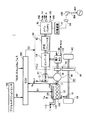
図1を参照して、本実施の形態に係る車両1の全体ブロック図が説明される。車両1は、エンジン10と、第1モータジェネレータ(以下、第1MGと記載する)20と、第2モータジェネレータ(以下、第2MGと記載する)30と、PCU(Power Control Unit)60と、メインバッテリ70と、充電装置78と、駆動輪80と、トランスミッション86と、ECU(Electronic Control Unit)200とを含む。トランスミッション86は、駆動軸16と、動力分割装置40と、減速機58と、ドライブシャフト82とを含む。
With reference to FIG. 1, an overall block diagram of a
この車両1は、エンジン10および第2MG30の少なくとも一方から出力される駆動力によって走行する。エンジン10が発生する動力は、動力分割装置40によって2経路に分割される。2経路のうちの一方の経路は減速機58を介して駆動輪80へ伝達される経路であり、他方の経路は第1MG20へ伝達される経路である。
The
第1MG20および第2MG30は、たとえば、三相交流回転電機である。第1MG20および第2MG30は、PCU60によって駆動される。 First MG 20 and second MG 30 are, for example, three-phase AC rotating electric machines. First MG 20 and second MG 30 are driven by PCU 60.
第1MG20は、動力分割装置40によって分割されたエンジン10の動力を用いて発電してPCU60を経由してメインバッテリ70を充電するジェネレータとしての機能を有する。また、第1MG20は、メインバッテリ70からの電力を受けてエンジン10の出力軸であるクランク軸を回転させる。これによって、第1MG20は、エンジン10を始動するスタータとしての機能を有する。
First MG 20 has a function as a generator that generates power using the power of
第2MG30は、メインバッテリ70に蓄えられた電力および第1MG20により発電された電力の少なくともいずれか一方を用いて駆動輪80に駆動力を与える駆動用モータとしての機能を有する。また、第2MG30は、回生制動によって発電された電力を用いてPCU60を経由してメインバッテリ70を充電するためのジェネレータとしての機能を有する。
Second MG 30 has a function as a drive motor that applies driving force to drive
エンジン10は、たとえば、ガソリンエンジンやディーゼルエンジン等の内燃機関である。エンジン10は、複数の気筒102と点火装置104と吸気通路112とを含む。点火装置104は、各気筒内に設けられる複数の点火プラグを含む。点火装置104は、ECU200からの制御信号S1に基づいて、適切な点火時期に各気筒の点火プラグをスパークさせる。さらに、エンジン10には、エンジン10のクランク軸の回転速度(以下、エンジン回転速度と記載する)Neを検出するためのエンジン回転速度センサ11が設けられる。エンジン回転速度センサ11は、検出されたエンジン回転速度Neを示す信号をECU200に送信する。
The
動力分割装置40は、駆動輪80を回転させるための駆動軸16、エンジン10の出力軸および第1MG20の回転軸の三要素の各々を機械的に連結する。動力分割装置40は、上述の三要素のうちのいずれか一つを反力要素とすることによって、他の2つの要素間での動力の伝達を可能とする。第2MG30の回転軸は、駆動軸16に連結される。
Power split
動力分割装置40は、サンギヤと、ピニオンギヤと、キャリアと、リングギヤとを含む遊星歯車機構である。ピニオンギヤは、サンギヤおよびリングギヤの各々と噛み合う。キャリアは、ピニオンギヤを自転可能に支持するとともに、エンジン10のクランク軸に連結される。サンギヤは、第1MG20の回転軸に連結される。リングギヤは、駆動軸16を介在して第2MG30の回転軸および減速機58に連結される。
Power split
減速機58は、動力分割装置40や第2MG30からの動力を駆動輪80に伝達する。また、減速機58は、駆動輪80が受けた路面からの反力を動力分割装置40や第2MG30に伝達する。
PCU60は、メインバッテリ70に蓄えられた直流電力を第1MG20および第2MG30を駆動するための交流電力に変換する。PCU60は、ECU200からの制御信号S2に基づいて制御される昇圧コンバータ62およびインバータ64を含む。
昇圧コンバータ62は、メインバッテリ70から受けた直流電力の電圧を昇圧してインバータ64に出力する。インバータ64は、昇圧コンバータ62が出力した直流電力を交流電力に変換して第1MG20および/または第2MG30に出力する。これにより、メインバッテリ70に蓄えられた電力を用いて第1MG20および/または第2MG30が駆動される。また、インバータ64は、第1MG20および/または第2MG30によって発電される交流電力を直流電力に変換して昇圧コンバータ62に出力する。昇圧コンバータ62は、インバータ64が出力した直流電力の電圧を降圧してメインバッテリ70へ出力する。これにより、第1MG20および/または第2MG30により発電された電力を用いてメインバッテリ70が充電される。なお、昇圧コンバータ62は、省略されてもよい。
メインバッテリ70は、蓄電装置であり、再充電可能な直流電源である。メインバッテリ70は、PCU60に接続される。メインバッテリ70としては、たとえば、ニッケル水素やリチウムイオン等の二次電池が用いられる。メインバッテリ70の電圧は、たとえば200V程度である。メインバッテリ70は、上述したように第1MG20および/または第2MG30により発電された電力を用いて充電される。なお、メインバッテリ70は、二次電池に限らず、直流電圧を生成できるもの、たとえば、キャパシタ、太陽電池、燃料電池等であってもよい。
The
メインバッテリ70には、メインバッテリ70の電池温度TBを検出するための電池温度センサ156と、メインバッテリ70の電流IBを検出するための電流センサ158と、メインバッテリ70の電圧VBを検出するための電圧センサ160とが設けられる。
The
電池温度センサ156は、電池温度TBを示す信号をECU200に送信する。電流センサ158は、電流IBを示す信号をECU200に送信する。電圧センサ160は、電圧VBを示す信号をECU200に送信する。
アクセルポジションセンサ162は、アクセルペダル(図示せず)の踏み込み量APを検出する。アクセルポジションセンサ162は、アクセルペダルの踏み込み量APを示す信号をECU200に送信する。
The
第1レゾルバ12は、第1MG20の回転速度Nm1を検出する。第1レゾルバ12は、検出された回転速度Nm1を示す信号をECU200に送信する。第2レゾルバ13は、第2MG30の回転速度Nm2を検出する。第2レゾルバ13は、検出された回転速度Nm2を示す信号をECU200に送信する。
The
車輪速センサ14は、駆動輪80の回転速度Nwを検出する。車輪速センサ14は、検出された回転速度Nwを示す信号をECU200に送信する。ECU200は、受信した回転速度Nwに基づいて車速Vを算出する。なお、ECU200は、回転速度Nwに代えて第2MG30の回転速度Nm2に基づいて車速Vを算出するようにしてもよい。
The
水温センサ106は、エンジン10の内部を流通する冷却水の温度Tw(以下、冷却水温Twと記載する)を検出する。水温センサ106は、検出された冷却水温Twを示す信号をECU200に送信する。
The
吸気温センサ110は、エンジン10の吸気通路112を流通する空気の温度Ti(以下、吸気温Tiと記載する)を検出する。吸気温センサ110は、検出された吸気温Tiを示す信号をECU200に送信する。
The intake
充電装置78は、充電プラグ300が車両1のソケット84に取り付けられることによって外部電源302から供給される電力を用いてメインバッテリ70を充電する。充電プラグ300は、充電ケーブル304の一方端に接続される。充電ケーブル304の他方端は、外部電源302に接続される。充電装置78の正極端子は、メインバッテリ70の正極端子に接続され、充電装置78の負極端子は、メインバッテリ70の負極端子に接続される。なお、外部電源302は、たとえば、商用電源である。
The charging
ECU200は、エンジン10を制御するための制御信号S1を生成し、その生成した制御信号S1をエンジン10へ出力する。また、ECU200は、PCU60を制御するための制御信号S2を生成し、その生成した制御信号S2をPCU60へ出力する。
ECU200は、エンジン10およびPCU60等を制御することによって車両1が最も効率よく運行できるようにハイブリッドシステム全体、すなわち、メインバッテリ70の充放電状態、エンジン10、第1MG20および第2MG30の動作状態を制御する。
ECU200は、アクセルペダルの踏み込み量APに対応する要求駆動力を算出する。ECU200は、算出された要求駆動力に応じて、第1MG20および第2MG30のトルクと、エンジン10の出力とを制御する。
上述したような構成を有する車両1においては、発進時や低速走行時等であってエンジン10の効率が悪い場合には、エンジン10を停止させた状態で第2MG30のみによる走行が行なわれる。また、通常走行時には、たとえば動力分割装置40によりエンジン10の動力が2経路の動力に分けられる。一方の動力で駆動輪80が直接的に駆動される。他方の動力で第1MG20を駆動して発電が行なわれる。このとき、ECU200は、発電された電力を用いて第2MG30を駆動させる。このように第2MG30を駆動させることにより駆動輪80の駆動補助が行なわれる。
In the
車両1の減速時には、駆動輪80の回転に従動する第2MG30がジェネレータとして機能して回生制動が行なわれる。回生制動によって回収した電力は、メインバッテリ70に蓄えられる。なお、ECU200は、蓄電装置の残容量(以下の説明においては、SOC(State of Charge)と記載する)が低下し、充電が特に必要な場合には、エンジン10の出力を増加させて第1MG20による発電量を増加させる。これにより、メインバッテリ70のSOCが増加させられる。また、ECU200は、低速走行時でも必要に応じてエンジン10からの駆動力を増加させる制御を行なう場合もある。たとえば、上述のようにメインバッテリ70の充電が必要な場合や、エアコン等の補機が駆動される場合や、エンジン10の冷却水の温度を所定温度まで上げる場合等である。
When the
また、車両1においては、EV優先モードおよびHV優先モードのうちのいずれか一方のモードが選択される。EV優先モードおよびHV優先モードは、いずれもエンジン10を停止させた状態で第2MG30を用いて車両1を走行させる第1制御とエンジン10および第2MG30を用いて車両1を走行させる第2制御とを実行するモードである。
Further, in the
EV優先モードは、HV優先モードよりもエンジン10を停止させた状態で第2MG30によって車両1が走行されやすいモードである。
The EV priority mode is a mode in which the
たとえば、HV優先モードが選択されているときよりもEV優先モードが選択されているときの第1制御を実行する頻度、時間および割合のうちの少なくともいずれか一つが大きくなるように車両1が制御される。
For example, the
たとえば、外部電源302を用いてメインバッテリ70を充電した直後の車両1のシステムの起動時においては、EV優先モードが選択されるようにしてもよい。あるいは、運転者のスイッチ操作に応じてEV優先モードが選択されるようにしてもよい。
For example, the EV priority mode may be selected when starting up the system of the
ECU200は、EV優先モードが選択されている場合には、第1制御を実行できるときに第1制御を実行し、第1制御の実行ができないときに第2制御を実行する。
When the EV priority mode is selected,
具体的には、ECU200は、EV優先モードが選択されている場合には、メインバッテリ70のSOCがしきい値SOC(0)以上であるときに第1制御を実行して、エンジン10を停止させた状態で第2MG30を用いて車両1を走行させる。
Specifically, when EV priority mode is selected,
また、ECU200は、EV優先モードが選択されている場合でも、メインバッテリ70のSOCがしきい値よりも低下したとき、あるいは、第2MG30の出力の上限値を超える駆動力が要求されたときには第2制御を実行するためにエンジン10を始動させる。しきい値SOC(0)は、エンジン10を停止させた状態で第2MG30を用いて車両1を走行させるEV走行が許可されるSOCの範囲の下限値である。
Further, even when the EV priority mode is selected,
HV優先モードは、EV優先モードよりもエンジン10と第2MG30とによって車両1が走行されやすいモードである。たとえば、EV優先モードが選択されているときよりもHV優先モードが選択されているときの第2制御を実行する頻度、時間および割合のうちの少なくともいずれか一つが大きくなるように車両1が制御される。
The HV priority mode is a mode in which the
たとえば、EV優先モードの選択中にメインバッテリ70のSOCの低下によってエンジン10が始動する場合に、エンジン10の始動後にEV優先モードからHV優先モードに自動的に移行するようにしてもよい。あるいは、運転者のスイッチ操作に応じてHV優先モードが選択されるようにしてもよい。
For example, when the
ECU200は、HV優先モードが選択されている場合には、第2制御を実行できるときに第2制御を実行し、第2制御の実行ができないときに第1制御を実行する。
When the HV priority mode is selected,
具体的には、ECU200は、HV優先モードが選択されている場合には、メインバッテリ70のSOCがしきい値SOC(2)(>SOC(1))以下であるときに第2制御を実行し、メインバッテリ70のSOCがしきい値SOC(2)よりも大きいときに第1制御を実行する。しきい値SOC(2)は、メインバッテリ70のSOCの上限値であって、たとえば、メインバッテリ70が満充電状態である場合に対応するSOCである。
Specifically, when the HV priority mode is selected,
以上のような構成を有する車両1において、EV優先モードとHV優先モードとのうちのいずれが選択されるかによって、エンジン10の始動時の点火時期を適切に設定する必要がある。これは、選択されたモードによってエンジン10の始動時における状態が異なる場合があるためである。特に、外部電源302を用いてメインバッテリ70が充電され、充電後にEV優先モードが選択された状態で車両1が走行する場合においては、HV優先モードが選択されている場合よりもエンジン10が冷えた状態で始動する場合がある。また、EV優先モードが選択されている場合でも車両1に要求される駆動力が大きい場合には、要求される駆動力を発生させるためにエンジン10の出力を始動直後に上昇させる必要がある。そのため、EV優先モードの選択中に車両1の駆動力の要求に応じてエンジン10を始動させるときには、HV優先モードの選択中にエンジン10を始動させるときよりも、エンジン10の始動性あるいは排気ガスのエミッションが悪化する場合がある。
In the
そこで、本実施の形態においてECU200は、駆動力の要求に応じてエンジン10を始動させる場合には、EV優先モードが選択されているときのエンジン10の点火時期が、HV優先モードが選択されているときの点火時期よりも遅くなるようにエンジン10を制御する点に特徴を有する。
Therefore, in the present embodiment, when starting the
図2に、本実施の形態に係る車両1に搭載されたECU200の機能ブロック図を示す。ECU200は、初回始動判定部250と、モード判定部252と、自立始動判定部254と、点火時期決定部256と、始動制御部258とを含む。
FIG. 2 shows a functional block diagram of
初回始動判定部250は、エンジン10の初回始動を行なうか否かを判定する。なお、エンジン10の初回始動とは、運転者によってスタートスイッチが操作されることによって車両1のシステムが起動してから最初のエンジン10の始動をいう。
The initial
たとえば、初回始動判定部250は、エンジン10を始動させる場合であって、かつ、当該始動が初回である場合にエンジン10の初回始動を行なうと判定する。エンジン10を始動させる場合には、負荷要求始動によりエンジン10を始動させる場合と自立始動によりエンジン10を始動させる場合とがある。
For example, the initial
負荷要求始動によるエンジン10の始動とは、駆動力の要求に応じたエンジン10の始動であって、スロットルバルブの開度を変化させながらエンジン10を始動させる場合をいう。負荷要求始動には、たとえば、第2MG30の出力によって車両1に要求される駆動力が不足する場合(すなわち、要求駆動力を充足させるためにエンジン10の出力が必要となる場合)のエンジン10の始動が含まれる。
The start of the
初回始動判定部250は、たとえば、アクセルペダルの踏み込み量APがしきい値AP(0)以上である場合に、負荷要求始動によりエンジン10を始動させる場合であると判定する。あるいは、初回始動判定部250は、たとえば、アクセルペダルの踏み込み量APの変化量ΔAPがしきい値ΔAP(0)以上である場合に、負荷要求始動によりエンジン10を始動させる場合であると判定する。
For example, when the accelerator pedal depression amount AP is equal to or greater than the threshold value AP (0), the initial
なお、しきい値AP(0)およびしきい値ΔAP(0)は、要求駆動力を充足させるためにエンジン10の出力が必要であるか否かを判定するための値である。しきい値AP(0)またはしきい値ΔAP(0)は、車両の状態(たとえば、メインバッテリ70のSOCあるいは車速V等)によって変化する値であってもよいし、一定値であってもよい。
The threshold value AP (0) and the threshold value ΔAP (0) are values for determining whether or not the output of the
また、初回始動判定部250は、スロットル開度がしきい値以上である場合に、負荷要求始動によりエンジン10を始動させる場合であると判定してもよいし、あるいは、スロットル開度の変化量がしきい値以上である場合に、負荷要求始動によりエンジン10を始動させる場合であると判定してもよい。
Further, the initial
自立始動とは、駆動力の要求以外の要求に応じたエンジン10の始動である。自立始動には、エンジン10のスロットルバルブの開度を変化させることなくエンジン10を始動させる場合が含まれる。
The independent start is a start of the
具体的には、初回始動判定部250は、メインバッテリ70のSOCがしきい値SOC(0)よりも低下した場合、あるいは、車速Vがしきい値V(0)以上である場合に、自立始動によりエンジン10を始動させる場合であると判定する。なお、しきい値V(0)は、車両1の走行中にエンジン10の回転を停止させた場合に第1MG20が過回転状態となる場合の車速Vの下限値である。
Specifically, first time
また、初回始動判定部250は、エンジン10の初回始動とともにオン状態とされ、車両1のシステムの停止とともにオフ状態とされる始動フラグの状態に基づいて初回始動であるか否かを判定する。なお、初回始動判定部250は、たとえば、エンジン10の初回始動が行なわれると判定した場合に初回判定フラグをオンするようにしてもよい。
The initial
モード判定部252は、EV優先モードおよびHV優先モードのうちのいずれのモードが選択されているかを判定する。モード判定部252は、たとえば、EV優先モードが選択されているか否かを判定し、EV優先モードが選択されていないと判定された場合に、HV優先モードが選択されていると判定してもよい。
The
モード判定部252は、たとえば、EV優先モードの選択フラグがオン状態である場合に、EV優先モードが選択されていると判定し、選択フラグがオフ状態である場合に、HV優先モードが選択されていると判定してもよい。
For example, when the EV priority mode selection flag is on, the
EV優先モードの選択フラグは、たとえば、運転者がEV優先モードを選択するためのスイッチをオンした場合あるいは外部電源302を用いてメインバッテリ70が充電された後、最初に車両1のシステムが起動した場合にオン状態とされるようにしてもよい。
The EV priority mode selection flag is, for example, when the driver turns on a switch for selecting the EV priority mode or after the
また、EV優先モードの選択フラグは、たとえば、運転者がHV優先モードを選択するためのスイッチをオンした場合、EV優先モードを選択するためのスイッチをオフした場合、あるいは、EV優先モードの選択中にメインバッテリ70のSOCがしきい値SOC(0)よりも低下したことによってエンジン10を始動させた場合、オフ状態とされるようにしてもよい。
The EV priority mode selection flag is, for example, when the driver turns on the switch for selecting the HV priority mode, when the switch for selecting the EV priority mode is turned off, or when the EV priority mode is selected. When the
自立始動判定部254は、エンジン10の始動が自立始動によるものであるか、あるいは、負荷要求始動によるものであるかを判定する。自立始動判定部254は、エンジン10の始動が上述したような自立始動によるものであるか否かを判定し、自立始動によるものでないと判定された場合に上述したような負荷要求始動によるものであると判定してもよい。
The independent
なお、自立始動判定部254は、たとえば、エンジン10の始動が自立始動によるものである場合に、自立始動判定フラグをオン状態とし、エンジン10の始動が負荷要求始動によるものである場合に、自立始動判定フラグをオフ状態とするようにしてもよい。
Note that the self-sustained
点火時期決定部256は、初回始動判定部250、モード判定部252および自立始動判定部254の判定結果に基づいてエンジン10の始動時における点火時期の初期値を決定する。点火時期決定部256は、たとえば、図3に示すようにエンジンの始動状況を示す判定結果に対応したマップを選択する。また、点火時期決定部256は、選択されたマップとエンジン10の冷却水温Twとに基づいてエンジン10の始動時における点火時期の初期値を決定する。
The ignition
なお、本実施の形態においては、点火時期決定部256は、選択されたマップとエンジン10の冷却水温Twとに基づいてエンジン10の始動時における点火時期の初期値を決定するとして説明するが、たとえば、マップは、吸気温Tiと点火時期の初期値との関係を示す2次元マップであって、選択されたマップと吸気温Tiとに基づいてエンジン10の始動時における点火時期の初期値を決定してもよい。
In the present embodiment, the ignition
あるいは、マップは、冷却水温Twと吸気温Tiと点火時期の初期値との関係を示す3次元マップであって、点火時期決定部256は、選択されたマップと冷却水温Twと吸気温Tiとに基づいてエンジン10の始動時における点火時期の初期値を決定してもよい。
Alternatively, the map is a three-dimensional map showing the relationship between the cooling water temperature Tw, the intake air temperature Ti, and the initial value of the ignition timing, and the ignition
点火時期決定部256は、エンジン10の初回始動であって、EV優先モードが選択されており、かつ、エンジン10の始動が自立始動によるものである場合には、マップAを選択する。なお、点火時期決定部256は、たとえば、初回判定フラグ、選択フラグおよび自立始動判定フラグがいずれもオン状態である場合にマップAを選択してもよい。
The ignition
点火時期決定部256は、エンジン10の初回始動であって、HV優先モードが選択されており、かつ、エンジン10の始動が自立始動によるものである場合には、マップBを選択する。なお、点火時期決定部256は、たとえば、初回判定フラグおよび自立始動判定フラグがオン状態であって、かつ、選択フラグがオフである場合には、マップBを選択してもよい。
The ignition
点火時期決定部256は、エンジン10の初回始動ではなく、かつ、エンジン10の始動が自立始動によるものである場合には、走行モードの選択状態に関わらず、マップCを選択する。なお、点火時期決定部256は、たとえば、初回判定フラグがオフ状態であって、自立始動判定フラグがオン状態である場合には、選択フラグの状態に関わらずマップCを選択してもよい。
The ignition
点火時期決定部256は、エンジン10の初回始動であって、EV優先モードが選択されており、かつ、エンジン10の始動が負荷要求始動によるものである場合には、マップDを選択する。なお、点火時期決定部256は、たとえば、初回判定フラグおよび選択フラグがいずれもオン状態であって、かつ、自立始動判定フラグがオフ状態である場合には、マップDを選択してもよい。
The ignition
点火時期決定部256は、エンジン10の初回始動であって、HV優先モードが選択されており、かつ、エンジン10の始動が負荷要求始動によるものである場合には、マップEを選択する。なお、点火時期決定部256は、初回判定フラグがオン状態であって、かつ、選択フラグおよび自立始動判定フラグがいずれもオフ状態である場合には、マップEを選択してもよい。
The ignition
点火時期決定部256は、エンジン10の初回始動ではなく、かつ、エンジン10の始動が負荷要求始動によるものである場合には、走行モードの選択状態に関わらず、マップFを選択する。なお、点火時期決定部256は、初回判定フラグおよび自立始動判定フラグがいずれもオフ状態である場合には、選択フラグの状態に関わらずマップFを選択してもよい。
The ignition
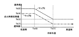
図4に示すように、マップD(図4の実線)とマップE(図4の破線)とを比較した場合、マップDは、マップEよりも同一の冷却水温Twに対して遅角側の点火時期になるように定められる。すなわち、車両1のシステムが起動してから最初に駆動力の要求に応じてエンジン10を始動させる場合において、EV優先モードの選択中にマップDによって決定される点火時期の初期値は、HV優先モードの選択中にマップEによって決定される点火時期の初期値よりも遅角側の点火時期が決定される。
As shown in FIG. 4, when the map D (solid line in FIG. 4) and the map E (broken line in FIG. 4) are compared, the map D is more retarded than the map E with respect to the same cooling water temperature Tw. It is determined to be the ignition timing. That is, when the
マップEでは、たとえば、冷却水温TwがTw(0)よりも低い場合、点火時期の初期値は、Tb(0)となる。一方、冷却水温TwがTw(1)よりも高い場合、点火時期の初期値は、Tb(0)よりも遅角側のTb(3)となる。さらに、冷却水温TwがTw(0)からTw(1)の間である場合には、冷却水温Twの増加に対してTb(0)とTb(3)との間で線形に変化した値が点火時期の初期値となる。 In the map E, for example, when the coolant temperature Tw is lower than Tw (0), the initial value of the ignition timing is Tb (0). On the other hand, when the coolant temperature Tw is higher than Tw (1), the initial value of the ignition timing is Tb (3) that is retarded from Tb (0). Further, when the cooling water temperature Tw is between Tw (0) and Tw (1), the value that linearly changes between Tb (0) and Tb (3) with respect to the increase in the cooling water temperature Tw. This is the initial value of the ignition timing.
マップDでは、たとえば、冷却水温TwがTw(0)よりも低い場合、点火時期の初期値は、Tb(0)よりも遅角側のTb(1)となる。一方、冷却水温TwがTw(1)よりも高い場合、点火時期の初期値は、Tb(1)およびTb(3)よりも遅角側のTb(2)となる。さらに、冷却水温TwがTw(0)からTw(1)の間である場合には、冷却水温Twの増加に対してTb(1)とTb(2)との間で線形に変化した値が点火時期の初期値となる。 In the map D, for example, when the coolant temperature Tw is lower than Tw (0), the initial value of the ignition timing is Tb (1) that is retarded from Tb (0). On the other hand, when the coolant temperature Tw is higher than Tw (1), the initial value of the ignition timing is Tb (2) that is retarded from Tb (1) and Tb (3). Further, when the cooling water temperature Tw is between Tw (0) and Tw (1), a value that linearly changes between Tb (1) and Tb (2) with respect to the increase in the cooling water temperature Tw. This is the initial value of the ignition timing.
本実施の形態においては、マップDは、少なくとも同一の冷却水温TwにおいてマップEよりも遅角側の点火時期になるように定められればよく、図4に示すように、マップDとマップEとが縦軸方向にオフセットした関係となることに限定されるものではない。また、マップDおよびマップEでは、冷却水温TwがTw(0)よりも低い場合およびTw(1)よりも高い場合に一定値となるとして説明したが、少なくともいずれか一方の場合に冷却水温Twの変化に対して線形あるいは非線形で変化してもよい。さらに、マップDおよびマップEにおいて、冷却水温TwがTw(0)とTw(1)との間である場合には、冷却水温Twの増加に対してTb(1)とTb(2)との間で非線形に変化した値が点火時期の初期値となるようにしてもよい。 In the present embodiment, the map D only needs to be determined so that the ignition timing is on the retard side with respect to the map E at least at the same cooling water temperature Tw. As shown in FIG. Is not limited to the relationship offset in the vertical axis direction. Further, in the map D and the map E, it has been described that the cooling water temperature Tw is constant when the cooling water temperature Tw is lower than Tw (0) and higher than Tw (1), but the cooling water temperature Tw is at least one of the cases. It may change linearly or non-linearly with respect to the change of. Furthermore, in the map D and the map E, when the cooling water temperature Tw is between Tw (0) and Tw (1), Tb (1) and Tb (2) are increased with respect to the increase in the cooling water temperature Tw. A value that changes in a non-linear manner may be the initial value of the ignition timing.
図5に示すように、マップB(図5の一点鎖線)とマップC(図5の実線)とを比較した場合、マップCは、マップBよりも同一の冷却水温Twに対して遅角側の点火時期になるように定められる。すなわち、車両1のシステムが起動してから停止するまでの間における最初のエンジン10の始動時の点火時期の初期値は、2回目以降のエンジン10の始動時(間欠始動時)の点火時期の初期値と異なるように決定される。具体的には、車両1のシステムが起動してから停止するまでの間における2回目以降のエンジンの始動時の点火時期の初期値が、最初のエンジン10の始動時の点火時期の初期値よりも遅角側になるように決定される。
As shown in FIG. 5, when the map B (the chain line in FIG. 5) and the map C (the solid line in FIG. 5) are compared, the map C is more retarded than the map B with respect to the same cooling water temperature Tw. It is determined to be the ignition timing. That is, the initial value of the ignition timing at the start of the
なお、図5のマップBとマップCとの関係は、Tb(0)−Tb(3)をTb(4)−Tb(7)にそれぞれ置き換えた点以外は、図4のマップDとマップEとの関係と同様の関係である。そのため、その詳細な説明は繰返されない。 The relationship between the map B and the map C in FIG. 5 is the same as the map D and the map E in FIG. 4 except that Tb (0) -Tb (3) is replaced with Tb (4) -Tb (7). It is the same relationship as the relationship. Therefore, detailed description thereof will not be repeated.
本実施の形態においては、マップCは、少なくとも同一の冷却水温TwにおいてマップBよりも遅角側の点火時期になるように定められればよく、図5に示すように、マップBとマップCとが縦軸方向に縦軸方向にオフセットした関係となることに限定されるものではない。 In the present embodiment, the map C only needs to be determined so that the ignition timing is retarded from the map B at least at the same cooling water temperature Tw. As shown in FIG. Is not limited to the relationship in which the vertical axis direction is offset in the vertical axis direction.
なお、マップEとマップFとの関係は、マップBとマップCとの関係と同様である。すなわち、マップEは、マップFよりも同一の冷却水温Twに対して遅角側の点火時期になるように定められる。 The relationship between the map E and the map F is the same as the relationship between the map B and the map C. That is, the map E is determined such that the ignition timing is retarded with respect to the same coolant temperature Tw as the map F.
図6に示すように、マップB(図6の一点鎖線)とマップE(図6の破線)とを比較した場合、マップBは、マップEよりも同一の冷却水温Twに対して遅角側の点火時期になるように定められる。すなわち、駆動力の要求に応じてエンジン10を始動させるとき(負荷要求始動時)の点火時期の初期値は、駆動力以外の要求に応じてエンジン10を始動させるとき(自立始動時)の点火時期の初期値と異なるように決定される。具体的には、HV優先モードが選択されている場合には、駆動力以外の要求に応じてエンジン10を始動させるときの点火時期の初期値は、駆動力の要求に応じてエンジン10を始動させるときの点火時期よりも遅角側になるように決定される。
As shown in FIG. 6, when comparing map B (dashed line in FIG. 6) and map E (broken line in FIG. 6), map B is more retarded than map E with respect to the same coolant temperature Tw. It is determined to be the ignition timing. That is, the initial value of the ignition timing when starting the
なお、図6のマップBとマップEとの関係は、マップDをマップBに置き換えた点以外は、図4のマップDとマップEとの関係と同様の関係である。そのため、その詳細な説明は繰返されない。 The relationship between the map B and the map E in FIG. 6 is the same as the relationship between the map D and the map E in FIG. 4 except that the map D is replaced with the map B. Therefore, detailed description thereof will not be repeated.
本実施の形態においては、マップBは、少なくとも同一の冷却水温TwにおいてマップEよりも遅角側の点火時期になるように定められればよく、図6に示すように、マップBとマップEとが縦軸方向にオフセットした関係となることに限定されるものではない。 In the present embodiment, the map B only needs to be determined so that the ignition timing is retarded from the map E at least at the same cooling water temperature Tw. As shown in FIG. Is not limited to the relationship offset in the vertical axis direction.
なお、EV優先モードが選択されている場合においても、駆動力の要求に応じてエンジン10を始動させるとき(負荷要求始動時)の点火時期の初期値と、駆動力以外の要求に応じてエンジン10を始動させるとき(自立始動時)の点火時期の初期値とが異なるように決定されてもよい。たとえば、マップAは、少なくとも同一の冷却水温TwにおいてマップEよりも遅角側の点火時期になるように定められてもよい。
Even when the EV priority mode is selected, the initial value of the ignition timing when the
また、本実施の形態においては、マップAは、少なくとも同一の冷却水温TwにおいてマップEよりも遅角側の点火時期になるように定められる。すなわち、EV優先モードが選択されている場合の自立始動時の点火時期の初期値は、HV優先モードが選択されている場合の負荷要求始動時の点火時期の初期値よりも遅角側の点火時期になるように定められる。 Further, in the present embodiment, the map A is determined so that the ignition timing is on the retard side with respect to the map E at least at the same cooling water temperature Tw. That is, the initial value of the ignition timing at the time of self-sustained start when the EV priority mode is selected is the retarded ignition side relative to the initial value of the ignition timing at the time of load request start when the HV priority mode is selected. It is determined to be time.
初回始動時に用いられるマップA、B、DおよびEは、少なくとも始動性および排気ガスのエミッションの向上の観点から定められる。また、2回目以降の始動時(間欠始動時)に用いられるマップCおよびFは、始動性および排気ガスのエミッションの向上に加えて、始動時のショックおよびノッキングの抑制の観点で定められる。また、マップA−Eの各々では、冷却水温Twが高いときは、冷却水温Twが低いときに比べて遅角側になるように点火時期の初期値が定められる。 Maps A, B, D, and E used at the initial start are determined at least from the viewpoint of improving startability and exhaust gas emission. The maps C and F used at the second and subsequent start-ups (intermittent start-up) are determined in terms of suppression of shock and knocking at start-up in addition to improvement of startability and exhaust gas emission. Further, in each of the maps A to E, the initial value of the ignition timing is determined such that when the cooling water temperature Tw is high, the ignition timing is on the retard side compared to when the cooling water temperature Tw is low.
なお、点火時期決定部256は、エンジン10が始動した後においては、エンジン10の状態に応じて点火時期を補正してもよい。エンジン10が始動したとは、各気筒に燃料噴射が行なわれ、かつ、エンジン10の回転数が自立回転可能な所定回転数以上となる状態をいう。エンジン10の状態とは、たとえば、ノッキングの発生状態、駆動力が要求された状態あるいはEGR(Exhaust Gas Recirculation)量をいう。
The ignition
始動制御部258は、エンジン10を始動させる場合に、第1MG20を用いて初爆可能な所定の回転数以上になるようにエンジン10をクランキングさせる。始動制御部258は、エンジン10の回転数がクランキングによって初爆可能な回転数以上となる場合に、燃料噴射制御とともに点火時期決定部256によって決定された点火時期のタイミングで点火制御を実行して、エンジン10を始動させる。始動制御部258は、制御信号S1を生成して、エンジン10に送信する。
When the
本実施の形態において、初回始動判定部250と、モード判定部252と、自立始動判定部254と、点火時期決定部256と、始動制御部258とは、いずれもECU200のCPUがメモリに記憶されたプログラムを実行することにより実現される、ソフトウェアとして機能するものとして説明するが、ハードウェアにより実現されるようにしてもよい。なお、このようなプログラムは記憶媒体に記録されて車両に搭載される。
In the present embodiment, the initial
図7を参照して、本実施の形態に係る車両1に搭載されたECU200で実行されるプログラムの制御構造について説明する。
With reference to FIG. 7, a control structure of a program executed by
ステップ(以下、ステップをSと記載する)100にて、ECU200は、エンジン10の初回始動を行なうか否かを判定する。エンジン10の初回始動を行なう場合(S100にてYES)、処理はS102に移される。もしそうでない場合(S100にてNO)、処理はS116に移される。
In step (hereinafter, step is referred to as S) 100,
S102にて、ECU200は、EV優先モードが選択されているか否かを判定する。EV優先モードが選択されている場合(S102にてYES)、処理はS104に移される。もしそうでない場合(S102にてNO)、処理はS110に移される。
In S102,
S104にて、ECU200は、エンジン10の始動が自立始動によるものであるか否かを判定する。エンジン10の始動が自立始動によるものである場合(S104にてYES)、処理はS106に移される。もしそうでない場合(S104にてNO)、処理はS108に移される。
In S104,
S106にて、ECU200は、マップAを用いて点火時期の初期値を決定する。すなわち、ECU200は、冷却水温TwとマップAとに基づいて点火時期の初期値を決定する。S108にて、ECU200は、マップDを用いて点火時期の初期値を決定する。
In S106,
S110にて、ECU200は、エンジン10の始動が自立始動によるものであるか否かを判定する。エンジン10の始動が自立始動によるものである場合(S110にてYES)、処理はS112に移される。もしそうでない場合(S110にてNO)、処理はS114に移される。
In S110,
S112にて、ECU200は、マップBを用いて点火時期の初期値を決定する。S114にて、ECU200は、マップEを用いて点火時期の初期値を決定する。S116にて、ECU200は、エンジン10の始動が自立始動によるものであるか否かを判定する。エンジン10の始動が自立始動によるものである場合(S116にてYES)、処理はS118に移される。もしそうでない場合(S116にてNO)、処理はS120に移される。
In S112,
S118にて、ECU200は、マップCを用いて点火時期の初期値を決定する。S120にて、ECU200は、マップFを用いて点火時期の初期値を決定する。S122にて、ECU200は、決定された点火時期の初期値を用いてエンジン10の始動制御を実行する。
In S118,
以上のような構造およびフローチャートに基づく本実施の形態に係る車両1に搭載されたECU200の動作について説明する。
An operation of
<EV優先モードが選択されている場合(その1)>
たとえば、外部電源302を用いてメインバッテリ70を満充電状態まで充電した後に、EV優先モードが選択された状態で車両1を走行させる場合を想定する。このとき、EV優先モードが選択された状態であって、かつ、メインバッテリ70のSOCがしきい値SOC(0)以上であるため、車両1は、エンジン10を停止させた状態で第2MG30を用いて走行する。
<When EV priority mode is selected (part 1)>
For example, it is assumed that the
運転者が車両1を加速させるためにアクセルペダルを踏み込む場合には、エンジン10による駆動力を発生させるためにエンジン10の初回始動が行なわれる(S100にてYES)。EV優先モードが選択されており(S102にてYES)、かつ、エンジン10の始動が負荷要求始動によるものであるため(S104にてNO)、エンジン10の冷却水温TwとマップDとに基づいてエンジン10の始動時における点火時期の初期値が決定される(S108)。ECU200は、決定された点火時期の初期値に基づいてエンジン10の始動制御を実行する(S122)。
When the driver depresses the accelerator pedal in order to accelerate
エンジン10の始動後に、アクセルペダルの踏み込みが解除されるなどして、エンジン10による駆動力が必要でない場合には、エンジン10は、停止状態となる。その後、再びアクセルペダルが踏み込まれ、エンジン10による駆動力が必要となる場合には、エンジン10の2回目の始動が行なわれる(S100にてNO)。このとき、エンジン10の始動が負荷要求始動によるものであるため(S116にてNO)、エンジン10の冷却水温TwとマップFとに基づいてエンジン10の始動時における点火時期の初期値が決定される(S120)。ECU200は、決定された点火時期の初期値に基づいてエンジン10の始動制御を実行する(S122)。
If the driving force of the
なお、エンジン10の2回目の始動が、たとえば、メインバッテリ70のSOCがしきい値SOC(0)よりも低下した場合の自立始動によるものである場合(S116にてYES)、エンジン10の冷却水温TwとマップCとに基づいてエンジン10の始動時における点火時期の初期値が決定される(S118)。
If the second start of
また、EV優先モードの選択中のエンジン10の初回始動が、たとえば、メインバッテリ70のSOCがしきい値SOC(0)よりも低下した場合の自立始動によるものである場合(S104にてYES)、エンジン10の冷却水温TwとマップAとに基づいてエンジン10の始動時における点火時期の初期値が決定される(S106)。
Further, when the initial start of
<HV優先モードが選択されている場合>
たとえば、外部電源302を用いてメインバッテリ70を満充電状態まで充電した後に、EV優先モードが選択された状態で車両1を走行させる場合を想定する。エンジン10を停止させた状態で第2MG30を用いて車両1が走行しているときに、運転者の操作によってEV優先モードからHV優先モードに切り換えら、運転者が車両1を加速させるためにアクセルペダルを踏み込む場合には、エンジン10の初回始動が行なわれる(S100にてYES)。HV優先モードが選択されており(S102にてNO)、かつ、エンジン10の始動が負荷要求始動によるものであるため(S110にてNO)、エンジン10の冷却水温TwとマップEとに基づいてエンジン10の始動時における点火時期の初期値が決定される(S114)。ECU200は、決定された点火時期の初期値に基づいてエンジン10の始動制御を実行して(S122)、エンジン10を始動させる。
<When HV priority mode is selected>
For example, it is assumed that the
なお、エンジン10の始動がたとえば、SOCがしきい値SOC(0)よりも低下した場合の自立始動によるものである場合(S110にてYES)、エンジン10の冷却水温TwとマップBとに基づいてエンジン10の始動時における点火時期の初期値が決定される(S112)。
When
本実施の形態に係る、外部電源302を用いた充電が可能な車両1においては、外部電源302を用いた充電後に車両1の発進時にEV優先モードが選択される場合には、運転者の加速の要求に応じてエンジン10を始動させる場合には、エンジン10の始動直後に出力を発生させる必要がある。特に、EV優先モードが選択されている場合には、HV優先モードよりもエンジン10の始動直前の放置時間が長い。そのため、EV優先モードが選択されている場合であって、かつ、負荷要求始動によるエンジン10の始動が行なわれる場合に選択されるマップDに基づいて決定される点火時期の初期値を、HV優先モードが選択されている場合であって、かつ、負荷要求始動によるエンジン10の始動が行なわれる場合に選択されるマップEに基づいて決定される点火時期の初期値よりも遅いタイミングとすることによって、エンジン10の始動性の向上と、排気ガスのエミッションの改善とが図られる。したがって、ハイブリッド車両に搭載された内燃機関の始動時に適切な点火時期を決定する車両および車両用制御方法を提供することができる。
In the
なお、図1では、駆動輪80を前輪とする車両1を一例として示したが、特にこのような駆動方式に限定されるものではない。たとえば、車両1は、後輪を駆動輪とするものであってもよい。または、車両1は、図1の第2MG30が前輪の駆動軸16に代えて、後輪を駆動するための駆動軸に連結される車両であってもよい。また、駆動軸16と減速機58との間あるいは駆動軸16と第2MG30との間に変速機構が設けられてもよい。あるいは、車両1は、エンジン10の出力軸に第1MG20が直結し、第2MG30が省略され、動力分割装置40に代えてクラッチを有する変速機構を含むものであってもよい。
In addition, in FIG. 1, although the
また、本実施の形態において、負荷要求始動によるエンジン10の初回始動時にEV優先モードが選択されている場合の点火時期の初期値が、HV優先モードが選択されているときの点火時期の初期値よりも遅角側の点火時期であるとして説明したが、たとえば、負荷要求始動による2回目以降のエンジン10の始動時にEV優先モードが選択されている場合の点火時期の初期値が、HV優先モードが選択されている場合の点火時期の初期値よりも遅角側の点火時期としてもよい。
In the present embodiment, the initial value of the ignition timing when the EV priority mode is selected when the
今回開示された実施の形態はすべての点で例示であって制限的なものではないと考えられるべきである。本発明の範囲は上記した説明ではなくて特許請求の範囲によって示され、特許請求の範囲と均等の意味および範囲内でのすべての変更が含まれることが意図される。 The embodiment disclosed this time should be considered as illustrative in all points and not restrictive. The scope of the present invention is defined by the terms of the claims, rather than the description above, and is intended to include any modifications within the scope and meaning equivalent to the terms of the claims.
1 車両、10 エンジン、11 エンジン回転速度センサ、12 第1レゾルバ、13 第2レゾルバ、14 車輪速センサ、16 駆動軸、20 第1MG、30 第2MG、40 動力分割装置、58 減速機、62 昇圧コンバータ、64 インバータ、70 メインバッテリ、78 充電装置、80 駆動輪、82 ドライブシャフト、84 ソケット、86 トランスミッション、102 気筒、104 点火装置、106 水温センサ、110 吸気温センサ、112 吸気通路、156 電池温度センサ、158 電流センサ、160 電圧センサ、162 アクセルポジションセンサ、200 ECU、250 初回始動判定部、252 モード判定部、254 自立始動判定部、256 点火時期決定部、258 始動制御部、300 充電プラグ、302 外部電源、304 充電ケーブル。
DESCRIPTION OF
Claims (9)
車両に駆動力を発生させるための回転電機と、
前記車両の状態に応じて前記内燃機関を制御するための制御部とを含み、
前記制御部は、前記駆動力の要求に応じて前記内燃機関を始動させる場合には、第1モードが選択されているときの前記内燃機関の点火時期が、第2モードが選択されているときの前記点火時期よりも遅くなるように前記内燃機関を制御し、
前記第1モードは、前記第2モードよりも、前記内燃機関を停止させた状態で前記回転電機によって前記車両が走行されやすいモードである、車両。 An internal combustion engine;
A rotating electric machine for generating driving force in the vehicle;
A control unit for controlling the internal combustion engine according to the state of the vehicle,
When the control unit starts the internal combustion engine in response to a request for the driving force, the ignition timing of the internal combustion engine when the first mode is selected, and when the second mode is selected Controlling the internal combustion engine to be later than the ignition timing of
The vehicle in which the first mode is a mode in which the vehicle is more easily traveled by the rotating electrical machine with the internal combustion engine stopped than in the second mode.
前記制御部は、前記第1モードが選択されている場合には、前記蓄電装置の残容量が第1しきい値よりも低下した場合に、前記内燃機関が始動するように前記内燃機関を制御し、前記第2モードが選択されている場合には、前記残容量が第2しきい値よりも高い状態を維持するように前記車両を制御する、請求項1〜6のいずれかに記載の車両。 The vehicle further includes a power storage device for supplying electric power to the rotating electrical machine,
When the first mode is selected, the control unit controls the internal combustion engine to start the internal combustion engine when the remaining capacity of the power storage device falls below a first threshold value. And when the said 2nd mode is selected, the said vehicle is controlled so that the said remaining capacity may maintain a state higher than a 2nd threshold value. vehicle.
前記車両は、
第2回転電機と、
前記駆動軸、前記内燃機関の出力軸および前記第2回転電機の回転軸の三要素の各々を機械的に連結し、前記三要素のうちのいずれか一つを反力要素とすることによって、他の2つの要素間での動力伝達が可能な動力伝達装置とをさらに含む、請求項1〜7のいずれかに記載の車両。 The rotating electrical machine is a first rotating electrical machine for driving the vehicle by rotating a drive shaft of the vehicle,
The vehicle is
A second rotating electrical machine;
By mechanically connecting each of the three elements of the drive shaft, the output shaft of the internal combustion engine, and the rotation shaft of the second rotating electrical machine, one of the three elements is a reaction force element The vehicle according to any one of claims 1 to 7, further comprising a power transmission device capable of transmitting power between the other two elements.
前記駆動力の要求を検出するステップと、
前記駆動力の要求に応じて前記内燃機関を始動させる場合に、第1モードが選択されているときの前記内燃機関の点火時期が、第2モードが選択されている場合の前記点火時期よりも遅くなるように前記内燃機関を制御するステップとを含み、
前記第1モードは、前記第2モードよりも、前記内燃機関を停止させた状態で前記回転電機によって前記車両が走行されやすいモードである、車両用制御方法。 A vehicle control method used in a vehicle equipped with an internal combustion engine, a rotating electrical machine for generating a driving force for the vehicle, and a power storage device for supplying electric power to the rotating electrical machine,
Detecting the request for the driving force;
When starting the internal combustion engine in response to a request for the driving force, the ignition timing of the internal combustion engine when the first mode is selected is greater than the ignition timing when the second mode is selected. Controlling the internal combustion engine to slow down,
The first mode is a vehicle control method in which the vehicle is more easily driven by the rotating electrical machine in a state where the internal combustion engine is stopped than in the second mode.
Priority Applications (3)
| Application Number | Priority Date | Filing Date | Title |
|---|---|---|---|
| JP2011039931A JP5617691B2 (en) | 2011-02-25 | 2011-02-25 | Vehicle and vehicle control method |
| CN201210043796.XA CN102649428B (en) | 2011-02-25 | 2012-02-23 | Vehicle and vehicle control method |
| US13/404,830 US9296384B2 (en) | 2011-02-25 | 2012-02-24 | Vehicle and vehicle control method |
Applications Claiming Priority (1)
| Application Number | Priority Date | Filing Date | Title |
|---|---|---|---|
| JP2011039931A JP5617691B2 (en) | 2011-02-25 | 2011-02-25 | Vehicle and vehicle control method |
Publications (2)
| Publication Number | Publication Date |
|---|---|
| JP2012176652A true JP2012176652A (en) | 2012-09-13 |
| JP5617691B2 JP5617691B2 (en) | 2014-11-05 |
Family
ID=46691575
Family Applications (1)
| Application Number | Title | Priority Date | Filing Date |
|---|---|---|---|
| JP2011039931A Active JP5617691B2 (en) | 2011-02-25 | 2011-02-25 | Vehicle and vehicle control method |
Country Status (3)
| Country | Link |
|---|---|
| US (1) | US9296384B2 (en) |
| JP (1) | JP5617691B2 (en) |
| CN (1) | CN102649428B (en) |
Families Citing this family (4)
| Publication number | Priority date | Publication date | Assignee | Title |
|---|---|---|---|---|
| JP5811287B2 (en) * | 2012-11-05 | 2015-11-11 | トヨタ自動車株式会社 | vehicle |
| KR101338463B1 (en) * | 2012-11-23 | 2013-12-10 | 기아자동차주식회사 | Method and system for controlling start of hybrid electric vehicle |
| JP6156431B2 (en) | 2015-04-09 | 2017-07-05 | トヨタ自動車株式会社 | Engine control device |
| JP6288006B2 (en) * | 2015-08-25 | 2018-03-07 | トヨタ自動車株式会社 | Engine control device |
Citations (5)
| Publication number | Priority date | Publication date | Assignee | Title |
|---|---|---|---|---|
| JP2001090581A (en) * | 1999-09-27 | 2001-04-03 | Toyota Motor Corp | Control device for internal combustion engine |
| JP2004346811A (en) * | 2003-05-21 | 2004-12-09 | Toyota Motor Corp | Hybrid vehicle and method for starting internal combustion engine mounted on the same |
| JP2005061234A (en) * | 2003-08-12 | 2005-03-10 | Toyota Motor Corp | Control device for internal combustion engine |
| JP2007126097A (en) * | 2005-11-07 | 2007-05-24 | Toyota Motor Corp | Hybrid vehicle and its control method |
| JP2010221897A (en) * | 2009-03-24 | 2010-10-07 | Toyota Motor Corp | Hybrid car, and misfire determination method for internal combustion engine |
Family Cites Families (15)
| Publication number | Priority date | Publication date | Assignee | Title |
|---|---|---|---|---|
| US6505594B1 (en) | 1999-08-23 | 2003-01-14 | Toyota Jidosha Kabushiki Kaisha | Control apparatus for internal combustion engine and method of controlling internal combustion engine |
| JP3653028B2 (en) * | 2001-10-17 | 2005-05-25 | 本田技研工業株式会社 | Power transmission control device for vehicle |
| JP2005009474A (en) * | 2003-05-26 | 2005-01-13 | Toyota Motor Corp | Power output apparatus and its control method |
| JP2009513402A (en) * | 2003-06-30 | 2009-04-02 | フオルクスワーゲン・アクチエンゲゼルシヤフト | Hybrid vehicle and method for driving a hybrid vehicle |
| JP4259527B2 (en) * | 2006-01-10 | 2009-04-30 | トヨタ自動車株式会社 | Vehicle control device |
| US7694760B2 (en) * | 2006-03-06 | 2010-04-13 | Ford Global Technologies, Llc | System and method for controlling vehicle operation |
| JP4678011B2 (en) * | 2007-06-01 | 2011-04-27 | トヨタ自動車株式会社 | Internal combustion engine ignition timing control device |
| JP2009047107A (en) * | 2007-08-21 | 2009-03-05 | Toyota Motor Corp | Engine rotation control device for vehicle |
| JP4655124B2 (en) * | 2008-08-25 | 2011-03-23 | トヨタ自動車株式会社 | Control device for hybrid vehicle |
| US8353265B2 (en) * | 2008-09-12 | 2013-01-15 | Ford Global Technologies, Llc | Efficient vehicle component heating |
| US20110276211A1 (en) * | 2009-01-09 | 2011-11-10 | Toyota Jidosha Kabushiki Kaisha | Control device for vehicle |
| JP5699520B2 (en) * | 2010-10-18 | 2015-04-15 | 日産自動車株式会社 | Vehicle idle control device |
| EP2639129B1 (en) * | 2010-11-08 | 2019-10-09 | Toyota Jidosha Kabushiki Kaisha | Hybrid automobile |
| US8972148B2 (en) * | 2011-03-30 | 2015-03-03 | Toyota Jidosha Kabushiki Kaisha | Vehicle, method and device for controlling engine |
| JP5807600B2 (en) * | 2012-03-28 | 2015-11-10 | トヨタ自動車株式会社 | Hybrid vehicle |
-
2011
- 2011-02-25 JP JP2011039931A patent/JP5617691B2/en active Active
-
2012
- 2012-02-23 CN CN201210043796.XA patent/CN102649428B/en not_active Expired - Fee Related
- 2012-02-24 US US13/404,830 patent/US9296384B2/en active Active
Patent Citations (5)
| Publication number | Priority date | Publication date | Assignee | Title |
|---|---|---|---|---|
| JP2001090581A (en) * | 1999-09-27 | 2001-04-03 | Toyota Motor Corp | Control device for internal combustion engine |
| JP2004346811A (en) * | 2003-05-21 | 2004-12-09 | Toyota Motor Corp | Hybrid vehicle and method for starting internal combustion engine mounted on the same |
| JP2005061234A (en) * | 2003-08-12 | 2005-03-10 | Toyota Motor Corp | Control device for internal combustion engine |
| JP2007126097A (en) * | 2005-11-07 | 2007-05-24 | Toyota Motor Corp | Hybrid vehicle and its control method |
| JP2010221897A (en) * | 2009-03-24 | 2010-10-07 | Toyota Motor Corp | Hybrid car, and misfire determination method for internal combustion engine |
Also Published As
| Publication number | Publication date |
|---|---|
| CN102649428A (en) | 2012-08-29 |
| CN102649428B (en) | 2015-05-06 |
| JP5617691B2 (en) | 2014-11-05 |
| US9296384B2 (en) | 2016-03-29 |
| US20120221185A1 (en) | 2012-08-30 |
Similar Documents
| Publication | Publication Date | Title |
|---|---|---|
| JP5716779B2 (en) | Hybrid car | |
| JP4910482B2 (en) | Variable valve operating device, control method thereof, and vehicle equipped with the same | |
| JP4519085B2 (en) | Control device for internal combustion engine | |
| JP5206819B2 (en) | Vehicle and vehicle control method | |
| JP4259527B2 (en) | Vehicle control device | |
| JP5598555B2 (en) | Vehicle and vehicle control method | |
| JP5928418B2 (en) | vehicle | |
| JP5892174B2 (en) | Vehicle control apparatus, vehicle including the same, and vehicle control method | |
| JP2008238965A (en) | Hybrid automobile and control method therefor | |
| CN102883933A (en) | Hybrid-vehicle control device and hybrid vehicle provided therewith | |
| WO2013042217A1 (en) | Vehicle and method for controlling vehicle | |
| EP2861442A1 (en) | Hybrid vehicle and control method for hybrid vehicle | |
| JPWO2012101802A1 (en) | Vehicle and vehicle control method | |
| JP2013141858A (en) | Controller for hybrid vehicle | |
| JP2016137784A (en) | Hybrid vehicle | |
| JP2019151305A (en) | Control device for hybrid vehicle | |
| JP5617691B2 (en) | Vehicle and vehicle control method | |
| JP2021138153A (en) | Control device of hybrid system | |
| JP5728447B2 (en) | Vehicle control device | |
| JP7418912B2 (en) | Hybrid system control device | |
| JP5673828B2 (en) | Hybrid vehicle | |
| JP2013132945A (en) | Control device of hybrid vehicle | |
| JPWO2013042217A1 (en) | Vehicle and vehicle control method | |
| JP2008149903A (en) | Power output device, its control method, and vehicle | |
| JP2019077299A (en) | Hybrid automobile |
Legal Events
| Date | Code | Title | Description |
|---|---|---|---|
| A131 | Notification of reasons for refusal |
Free format text: JAPANESE INTERMEDIATE CODE: A131 Effective date: 20121009 |
|
| A521 | Request for written amendment filed |
Free format text: JAPANESE INTERMEDIATE CODE: A523 Effective date: 20121207 |
|
| A131 | Notification of reasons for refusal |
Free format text: JAPANESE INTERMEDIATE CODE: A131 Effective date: 20130514 |
|
| A521 | Request for written amendment filed |
Free format text: JAPANESE INTERMEDIATE CODE: A523 Effective date: 20130711 |
|
| A131 | Notification of reasons for refusal |
Free format text: JAPANESE INTERMEDIATE CODE: A131 Effective date: 20140107 |
|
| TRDD | Decision of grant or rejection written | ||
| A01 | Written decision to grant a patent or to grant a registration (utility model) |
Free format text: JAPANESE INTERMEDIATE CODE: A01 Effective date: 20140819 |
|
| A61 | First payment of annual fees (during grant procedure) |
Free format text: JAPANESE INTERMEDIATE CODE: A61 Effective date: 20140901 |
|
| R151 | Written notification of patent or utility model registration |
Ref document number: 5617691 Country of ref document: JP Free format text: JAPANESE INTERMEDIATE CODE: R151 |