JP4519085B2 - Control device for internal combustion engine - Google Patents
Control device for internal combustion engine Download PDFInfo
- Publication number
- JP4519085B2 JP4519085B2 JP2006048908A JP2006048908A JP4519085B2 JP 4519085 B2 JP4519085 B2 JP 4519085B2 JP 2006048908 A JP2006048908 A JP 2006048908A JP 2006048908 A JP2006048908 A JP 2006048908A JP 4519085 B2 JP4519085 B2 JP 4519085B2
- Authority
- JP
- Japan
- Prior art keywords
- engine
- internal combustion
- combustion engine
- unit
- power
- Prior art date
- Legal status (The legal status is an assumption and is not a legal conclusion. Google has not performed a legal analysis and makes no representation as to the accuracy of the status listed.)
- Expired - Lifetime
Links
Images


Classifications
-
- B—PERFORMING OPERATIONS; TRANSPORTING
- B60—VEHICLES IN GENERAL
- B60L—PROPULSION OF ELECTRICALLY-PROPELLED VEHICLES; SUPPLYING ELECTRIC POWER FOR AUXILIARY EQUIPMENT OF ELECTRICALLY-PROPELLED VEHICLES; ELECTRODYNAMIC BRAKE SYSTEMS FOR VEHICLES IN GENERAL; MAGNETIC SUSPENSION OR LEVITATION FOR VEHICLES; MONITORING OPERATING VARIABLES OF ELECTRICALLY-PROPELLED VEHICLES; ELECTRIC SAFETY DEVICES FOR ELECTRICALLY-PROPELLED VEHICLES
- B60L58/00—Methods or circuit arrangements for monitoring or controlling batteries or fuel cells, specially adapted for electric vehicles
- B60L58/10—Methods or circuit arrangements for monitoring or controlling batteries or fuel cells, specially adapted for electric vehicles for monitoring or controlling batteries
- B60L58/12—Methods or circuit arrangements for monitoring or controlling batteries or fuel cells, specially adapted for electric vehicles for monitoring or controlling batteries responding to state of charge [SoC]
-
- B—PERFORMING OPERATIONS; TRANSPORTING
- B60—VEHICLES IN GENERAL
- B60K—ARRANGEMENT OR MOUNTING OF PROPULSION UNITS OR OF TRANSMISSIONS IN VEHICLES; ARRANGEMENT OR MOUNTING OF PLURAL DIVERSE PRIME-MOVERS IN VEHICLES; AUXILIARY DRIVES FOR VEHICLES; INSTRUMENTATION OR DASHBOARDS FOR VEHICLES; ARRANGEMENTS IN CONNECTION WITH COOLING, AIR INTAKE, GAS EXHAUST OR FUEL SUPPLY OF PROPULSION UNITS IN VEHICLES
- B60K6/00—Arrangement or mounting of plural diverse prime-movers for mutual or common propulsion, e.g. hybrid propulsion systems comprising electric motors and internal combustion engines
- B60K6/20—Arrangement or mounting of plural diverse prime-movers for mutual or common propulsion, e.g. hybrid propulsion systems comprising electric motors and internal combustion engines the prime-movers consisting of electric motors and internal combustion engines, e.g. HEVs
- B60K6/42—Arrangement or mounting of plural diverse prime-movers for mutual or common propulsion, e.g. hybrid propulsion systems comprising electric motors and internal combustion engines the prime-movers consisting of electric motors and internal combustion engines, e.g. HEVs characterised by the architecture of the hybrid electric vehicle
- B60K6/44—Series-parallel type
- B60K6/445—Differential gearing distribution type
-
- B—PERFORMING OPERATIONS; TRANSPORTING
- B60—VEHICLES IN GENERAL
- B60L—PROPULSION OF ELECTRICALLY-PROPELLED VEHICLES; SUPPLYING ELECTRIC POWER FOR AUXILIARY EQUIPMENT OF ELECTRICALLY-PROPELLED VEHICLES; ELECTRODYNAMIC BRAKE SYSTEMS FOR VEHICLES IN GENERAL; MAGNETIC SUSPENSION OR LEVITATION FOR VEHICLES; MONITORING OPERATING VARIABLES OF ELECTRICALLY-PROPELLED VEHICLES; ELECTRIC SAFETY DEVICES FOR ELECTRICALLY-PROPELLED VEHICLES
- B60L1/00—Supplying electric power to auxiliary equipment of vehicles
- B60L1/003—Supplying electric power to auxiliary equipment of vehicles to auxiliary motors, e.g. for pumps, compressors
-
- B—PERFORMING OPERATIONS; TRANSPORTING
- B60—VEHICLES IN GENERAL
- B60L—PROPULSION OF ELECTRICALLY-PROPELLED VEHICLES; SUPPLYING ELECTRIC POWER FOR AUXILIARY EQUIPMENT OF ELECTRICALLY-PROPELLED VEHICLES; ELECTRODYNAMIC BRAKE SYSTEMS FOR VEHICLES IN GENERAL; MAGNETIC SUSPENSION OR LEVITATION FOR VEHICLES; MONITORING OPERATING VARIABLES OF ELECTRICALLY-PROPELLED VEHICLES; ELECTRIC SAFETY DEVICES FOR ELECTRICALLY-PROPELLED VEHICLES
- B60L50/00—Electric propulsion with power supplied within the vehicle
- B60L50/10—Electric propulsion with power supplied within the vehicle using propulsion power supplied by engine-driven generators, e.g. generators driven by combustion engines
- B60L50/13—Electric propulsion with power supplied within the vehicle using propulsion power supplied by engine-driven generators, e.g. generators driven by combustion engines using AC generators and AC motors
-
- B—PERFORMING OPERATIONS; TRANSPORTING
- B60—VEHICLES IN GENERAL
- B60W—CONJOINT CONTROL OF VEHICLE SUB-UNITS OF DIFFERENT TYPE OR DIFFERENT FUNCTION; CONTROL SYSTEMS SPECIALLY ADAPTED FOR HYBRID VEHICLES; ROAD VEHICLE DRIVE CONTROL SYSTEMS FOR PURPOSES NOT RELATED TO THE CONTROL OF A PARTICULAR SUB-UNIT
- B60W10/00—Conjoint control of vehicle sub-units of different type or different function
- B60W10/04—Conjoint control of vehicle sub-units of different type or different function including control of propulsion units
- B60W10/06—Conjoint control of vehicle sub-units of different type or different function including control of propulsion units including control of combustion engines
-
- B—PERFORMING OPERATIONS; TRANSPORTING
- B60—VEHICLES IN GENERAL
- B60W—CONJOINT CONTROL OF VEHICLE SUB-UNITS OF DIFFERENT TYPE OR DIFFERENT FUNCTION; CONTROL SYSTEMS SPECIALLY ADAPTED FOR HYBRID VEHICLES; ROAD VEHICLE DRIVE CONTROL SYSTEMS FOR PURPOSES NOT RELATED TO THE CONTROL OF A PARTICULAR SUB-UNIT
- B60W20/00—Control systems specially adapted for hybrid vehicles
- B60W20/10—Controlling the power contribution of each of the prime movers to meet required power demand
- B60W20/15—Control strategies specially adapted for achieving a particular effect
-
- B—PERFORMING OPERATIONS; TRANSPORTING
- B60—VEHICLES IN GENERAL
- B60W—CONJOINT CONTROL OF VEHICLE SUB-UNITS OF DIFFERENT TYPE OR DIFFERENT FUNCTION; CONTROL SYSTEMS SPECIALLY ADAPTED FOR HYBRID VEHICLES; ROAD VEHICLE DRIVE CONTROL SYSTEMS FOR PURPOSES NOT RELATED TO THE CONTROL OF A PARTICULAR SUB-UNIT
- B60W30/00—Purposes of road vehicle drive control systems not related to the control of a particular sub-unit, e.g. of systems using conjoint control of vehicle sub-units
- B60W30/18—Propelling the vehicle
- B60W30/192—Mitigating problems related to power-up or power-down of the driveline, e.g. start-up of a cold engine
-
- F—MECHANICAL ENGINEERING; LIGHTING; HEATING; WEAPONS; BLASTING
- F02—COMBUSTION ENGINES; HOT-GAS OR COMBUSTION-PRODUCT ENGINE PLANTS
- F02D—CONTROLLING COMBUSTION ENGINES
- F02D11/00—Arrangements for, or adaptations to, non-automatic engine control initiation means, e.g. operator initiated
- F02D11/06—Arrangements for, or adaptations to, non-automatic engine control initiation means, e.g. operator initiated characterised by non-mechanical control linkages, e.g. fluid control linkages or by control linkages with power drive or assistance
- F02D11/10—Arrangements for, or adaptations to, non-automatic engine control initiation means, e.g. operator initiated characterised by non-mechanical control linkages, e.g. fluid control linkages or by control linkages with power drive or assistance of the electric type
- F02D11/105—Arrangements for, or adaptations to, non-automatic engine control initiation means, e.g. operator initiated characterised by non-mechanical control linkages, e.g. fluid control linkages or by control linkages with power drive or assistance of the electric type characterised by the function converting demand to actuation, e.g. a map indicating relations between an accelerator pedal position and throttle valve opening or target engine torque
-
- F—MECHANICAL ENGINEERING; LIGHTING; HEATING; WEAPONS; BLASTING
- F02—COMBUSTION ENGINES; HOT-GAS OR COMBUSTION-PRODUCT ENGINE PLANTS
- F02D—CONTROLLING COMBUSTION ENGINES
- F02D41/00—Electrical control of supply of combustible mixture or its constituents
- F02D41/0002—Controlling intake air
-
- F—MECHANICAL ENGINEERING; LIGHTING; HEATING; WEAPONS; BLASTING
- F02—COMBUSTION ENGINES; HOT-GAS OR COMBUSTION-PRODUCT ENGINE PLANTS
- F02D—CONTROLLING COMBUSTION ENGINES
- F02D41/00—Electrical control of supply of combustible mixture or its constituents
- F02D41/02—Circuit arrangements for generating control signals
- F02D41/04—Introducing corrections for particular operating conditions
- F02D41/06—Introducing corrections for particular operating conditions for engine starting or warming up
- F02D41/062—Introducing corrections for particular operating conditions for engine starting or warming up for starting
-
- B—PERFORMING OPERATIONS; TRANSPORTING
- B60—VEHICLES IN GENERAL
- B60L—PROPULSION OF ELECTRICALLY-PROPELLED VEHICLES; SUPPLYING ELECTRIC POWER FOR AUXILIARY EQUIPMENT OF ELECTRICALLY-PROPELLED VEHICLES; ELECTRODYNAMIC BRAKE SYSTEMS FOR VEHICLES IN GENERAL; MAGNETIC SUSPENSION OR LEVITATION FOR VEHICLES; MONITORING OPERATING VARIABLES OF ELECTRICALLY-PROPELLED VEHICLES; ELECTRIC SAFETY DEVICES FOR ELECTRICALLY-PROPELLED VEHICLES
- B60L2240/00—Control parameters of input or output; Target parameters
- B60L2240/40—Drive Train control parameters
- B60L2240/44—Drive Train control parameters related to combustion engines
- B60L2240/443—Torque
-
- B—PERFORMING OPERATIONS; TRANSPORTING
- B60—VEHICLES IN GENERAL
- B60L—PROPULSION OF ELECTRICALLY-PROPELLED VEHICLES; SUPPLYING ELECTRIC POWER FOR AUXILIARY EQUIPMENT OF ELECTRICALLY-PROPELLED VEHICLES; ELECTRODYNAMIC BRAKE SYSTEMS FOR VEHICLES IN GENERAL; MAGNETIC SUSPENSION OR LEVITATION FOR VEHICLES; MONITORING OPERATING VARIABLES OF ELECTRICALLY-PROPELLED VEHICLES; ELECTRIC SAFETY DEVICES FOR ELECTRICALLY-PROPELLED VEHICLES
- B60L2240/00—Control parameters of input or output; Target parameters
- B60L2240/80—Time limits
-
- B—PERFORMING OPERATIONS; TRANSPORTING
- B60—VEHICLES IN GENERAL
- B60L—PROPULSION OF ELECTRICALLY-PROPELLED VEHICLES; SUPPLYING ELECTRIC POWER FOR AUXILIARY EQUIPMENT OF ELECTRICALLY-PROPELLED VEHICLES; ELECTRODYNAMIC BRAKE SYSTEMS FOR VEHICLES IN GENERAL; MAGNETIC SUSPENSION OR LEVITATION FOR VEHICLES; MONITORING OPERATING VARIABLES OF ELECTRICALLY-PROPELLED VEHICLES; ELECTRIC SAFETY DEVICES FOR ELECTRICALLY-PROPELLED VEHICLES
- B60L2250/00—Driver interactions
- B60L2250/26—Driver interactions by pedal actuation
-
- B—PERFORMING OPERATIONS; TRANSPORTING
- B60—VEHICLES IN GENERAL
- B60L—PROPULSION OF ELECTRICALLY-PROPELLED VEHICLES; SUPPLYING ELECTRIC POWER FOR AUXILIARY EQUIPMENT OF ELECTRICALLY-PROPELLED VEHICLES; ELECTRODYNAMIC BRAKE SYSTEMS FOR VEHICLES IN GENERAL; MAGNETIC SUSPENSION OR LEVITATION FOR VEHICLES; MONITORING OPERATING VARIABLES OF ELECTRICALLY-PROPELLED VEHICLES; ELECTRIC SAFETY DEVICES FOR ELECTRICALLY-PROPELLED VEHICLES
- B60L2260/00—Operating Modes
- B60L2260/20—Drive modes; Transition between modes
- B60L2260/26—Transition between different drive modes
-
- B—PERFORMING OPERATIONS; TRANSPORTING
- B60—VEHICLES IN GENERAL
- B60L—PROPULSION OF ELECTRICALLY-PROPELLED VEHICLES; SUPPLYING ELECTRIC POWER FOR AUXILIARY EQUIPMENT OF ELECTRICALLY-PROPELLED VEHICLES; ELECTRODYNAMIC BRAKE SYSTEMS FOR VEHICLES IN GENERAL; MAGNETIC SUSPENSION OR LEVITATION FOR VEHICLES; MONITORING OPERATING VARIABLES OF ELECTRICALLY-PROPELLED VEHICLES; ELECTRIC SAFETY DEVICES FOR ELECTRICALLY-PROPELLED VEHICLES
- B60L2270/00—Problem solutions or means not otherwise provided for
- B60L2270/10—Emission reduction
- B60L2270/14—Emission reduction of noise
- B60L2270/145—Structure borne vibrations
-
- B—PERFORMING OPERATIONS; TRANSPORTING
- B60—VEHICLES IN GENERAL
- B60W—CONJOINT CONTROL OF VEHICLE SUB-UNITS OF DIFFERENT TYPE OR DIFFERENT FUNCTION; CONTROL SYSTEMS SPECIALLY ADAPTED FOR HYBRID VEHICLES; ROAD VEHICLE DRIVE CONTROL SYSTEMS FOR PURPOSES NOT RELATED TO THE CONTROL OF A PARTICULAR SUB-UNIT
- B60W20/00—Control systems specially adapted for hybrid vehicles
-
- B—PERFORMING OPERATIONS; TRANSPORTING
- B60—VEHICLES IN GENERAL
- B60W—CONJOINT CONTROL OF VEHICLE SUB-UNITS OF DIFFERENT TYPE OR DIFFERENT FUNCTION; CONTROL SYSTEMS SPECIALLY ADAPTED FOR HYBRID VEHICLES; ROAD VEHICLE DRIVE CONTROL SYSTEMS FOR PURPOSES NOT RELATED TO THE CONTROL OF A PARTICULAR SUB-UNIT
- B60W2710/00—Output or target parameters relating to a particular sub-units
- B60W2710/06—Combustion engines, Gas turbines
- B60W2710/0605—Throttle position
-
- B—PERFORMING OPERATIONS; TRANSPORTING
- B60—VEHICLES IN GENERAL
- B60W—CONJOINT CONTROL OF VEHICLE SUB-UNITS OF DIFFERENT TYPE OR DIFFERENT FUNCTION; CONTROL SYSTEMS SPECIALLY ADAPTED FOR HYBRID VEHICLES; ROAD VEHICLE DRIVE CONTROL SYSTEMS FOR PURPOSES NOT RELATED TO THE CONTROL OF A PARTICULAR SUB-UNIT
- B60W2710/00—Output or target parameters relating to a particular sub-units
- B60W2710/08—Electric propulsion units
- B60W2710/086—Power
- B60W2710/087—Power change rate
-
- B—PERFORMING OPERATIONS; TRANSPORTING
- B60—VEHICLES IN GENERAL
- B60W—CONJOINT CONTROL OF VEHICLE SUB-UNITS OF DIFFERENT TYPE OR DIFFERENT FUNCTION; CONTROL SYSTEMS SPECIALLY ADAPTED FOR HYBRID VEHICLES; ROAD VEHICLE DRIVE CONTROL SYSTEMS FOR PURPOSES NOT RELATED TO THE CONTROL OF A PARTICULAR SUB-UNIT
- B60W50/00—Details of control systems for road vehicle drive control not related to the control of a particular sub-unit, e.g. process diagnostic or vehicle driver interfaces
- B60W50/08—Interaction between the driver and the control system
- B60W50/12—Limiting control by the driver depending on vehicle state, e.g. interlocking means for the control input for preventing unsafe operation
-
- F—MECHANICAL ENGINEERING; LIGHTING; HEATING; WEAPONS; BLASTING
- F02—COMBUSTION ENGINES; HOT-GAS OR COMBUSTION-PRODUCT ENGINE PLANTS
- F02N—STARTING OF COMBUSTION ENGINES; STARTING AIDS FOR SUCH ENGINES, NOT OTHERWISE PROVIDED FOR
- F02N11/00—Starting of engines by means of electric motors
- F02N11/04—Starting of engines by means of electric motors the motors being associated with current generators
-
- F—MECHANICAL ENGINEERING; LIGHTING; HEATING; WEAPONS; BLASTING
- F02—COMBUSTION ENGINES; HOT-GAS OR COMBUSTION-PRODUCT ENGINE PLANTS
- F02N—STARTING OF COMBUSTION ENGINES; STARTING AIDS FOR SUCH ENGINES, NOT OTHERWISE PROVIDED FOR
- F02N2300/00—Control related aspects of engine starting
- F02N2300/10—Control related aspects of engine starting characterised by the control output, i.e. means or parameters used as a control output or target
- F02N2300/104—Control of the starter motor torque
-
- Y—GENERAL TAGGING OF NEW TECHNOLOGICAL DEVELOPMENTS; GENERAL TAGGING OF CROSS-SECTIONAL TECHNOLOGIES SPANNING OVER SEVERAL SECTIONS OF THE IPC; TECHNICAL SUBJECTS COVERED BY FORMER USPC CROSS-REFERENCE ART COLLECTIONS [XRACs] AND DIGESTS
- Y02—TECHNOLOGIES OR APPLICATIONS FOR MITIGATION OR ADAPTATION AGAINST CLIMATE CHANGE
- Y02T—CLIMATE CHANGE MITIGATION TECHNOLOGIES RELATED TO TRANSPORTATION
- Y02T10/00—Road transport of goods or passengers
- Y02T10/10—Internal combustion engine [ICE] based vehicles
- Y02T10/40—Engine management systems
-
- Y—GENERAL TAGGING OF NEW TECHNOLOGICAL DEVELOPMENTS; GENERAL TAGGING OF CROSS-SECTIONAL TECHNOLOGIES SPANNING OVER SEVERAL SECTIONS OF THE IPC; TECHNICAL SUBJECTS COVERED BY FORMER USPC CROSS-REFERENCE ART COLLECTIONS [XRACs] AND DIGESTS
- Y02—TECHNOLOGIES OR APPLICATIONS FOR MITIGATION OR ADAPTATION AGAINST CLIMATE CHANGE
- Y02T—CLIMATE CHANGE MITIGATION TECHNOLOGIES RELATED TO TRANSPORTATION
- Y02T10/00—Road transport of goods or passengers
- Y02T10/60—Other road transportation technologies with climate change mitigation effect
- Y02T10/62—Hybrid vehicles
-
- Y—GENERAL TAGGING OF NEW TECHNOLOGICAL DEVELOPMENTS; GENERAL TAGGING OF CROSS-SECTIONAL TECHNOLOGIES SPANNING OVER SEVERAL SECTIONS OF THE IPC; TECHNICAL SUBJECTS COVERED BY FORMER USPC CROSS-REFERENCE ART COLLECTIONS [XRACs] AND DIGESTS
- Y02—TECHNOLOGIES OR APPLICATIONS FOR MITIGATION OR ADAPTATION AGAINST CLIMATE CHANGE
- Y02T—CLIMATE CHANGE MITIGATION TECHNOLOGIES RELATED TO TRANSPORTATION
- Y02T10/00—Road transport of goods or passengers
- Y02T10/60—Other road transportation technologies with climate change mitigation effect
- Y02T10/70—Energy storage systems for electromobility, e.g. batteries
-
- Y—GENERAL TAGGING OF NEW TECHNOLOGICAL DEVELOPMENTS; GENERAL TAGGING OF CROSS-SECTIONAL TECHNOLOGIES SPANNING OVER SEVERAL SECTIONS OF THE IPC; TECHNICAL SUBJECTS COVERED BY FORMER USPC CROSS-REFERENCE ART COLLECTIONS [XRACs] AND DIGESTS
- Y02—TECHNOLOGIES OR APPLICATIONS FOR MITIGATION OR ADAPTATION AGAINST CLIMATE CHANGE
- Y02T—CLIMATE CHANGE MITIGATION TECHNOLOGIES RELATED TO TRANSPORTATION
- Y02T10/00—Road transport of goods or passengers
- Y02T10/60—Other road transportation technologies with climate change mitigation effect
- Y02T10/7072—Electromobility specific charging systems or methods for batteries, ultracapacitors, supercapacitors or double-layer capacitors
Landscapes
- Engineering & Computer Science (AREA)
- Mechanical Engineering (AREA)
- Chemical & Material Sciences (AREA)
- Combustion & Propulsion (AREA)
- Transportation (AREA)
- Power Engineering (AREA)
- General Engineering & Computer Science (AREA)
- Automation & Control Theory (AREA)
- Life Sciences & Earth Sciences (AREA)
- Sustainable Development (AREA)
- Sustainable Energy (AREA)
- Control Of Vehicle Engines Or Engines For Specific Uses (AREA)
- Hybrid Electric Vehicles (AREA)
- Control Of Throttle Valves Provided In The Intake System Or In The Exhaust System (AREA)
- Electrical Control Of Air Or Fuel Supplied To Internal-Combustion Engine (AREA)
- Combined Controls Of Internal Combustion Engines (AREA)
Description
本発明は内燃機関の制御装置に関し、特に、自動車に搭載される内燃機関を始動させる制御装置に関する。 The present invention relates to a control device for an internal combustion engine, and more particularly to a control device for starting an internal combustion engine mounted on an automobile.
エコノミーランニングシステムを搭載したエコラン車両や、モータ走行とエンジン走行とが切換えられるハイブリッド車両などにおいて、所定の停止条件が成立したときにエンジンを停止させ、所定の復帰条件が成立したときにエンジンを再始動させるといったエンジンの制御装置が知られている。 In an eco-run vehicle equipped with an economy running system or a hybrid vehicle in which motor driving and engine driving are switched, the engine is stopped when a predetermined stop condition is satisfied, and the engine is restarted when a predetermined return condition is satisfied. An engine control device for starting is known.
たとえば特開2002−339781号公報(特許文献1)は、エンジンの停止中にエンジン始動要求が発生した場合にエンジンの再始動を可能にする車両用エンジンの制御装置を開示する。この制御装置はエンジンの吸気管の圧力が小さいほどエンジン再始動時の吸入空気量を増大させる再始動制御手段を含む。この制御装置はエンジン停止中において筒内圧が残っているときに再始動要求がされた場合には、要求に見合うように吸入空気量を増大する。
上述の特開2002−339781号公報(特許文献1)に開示されるエンジンの再始動方法によれば、エンジン再始動時の吸入空気量が毎回異なることが起こり得る。このため以下のような問題が生じることが考えられる。 According to the engine restart method disclosed in the above-mentioned Japanese Patent Application Laid-Open No. 2002-339881 (Patent Document 1), it is possible that the intake air amount at the time of engine restart differs every time. For this reason, the following problems may occur.
たとえばハイブリッド車両では車両の走行状態がエンジンの効率が悪い領域であるとエンジンではなく電動機を作動させる。一方ハイブリッド車両では車両の走行状態がエンジンの効率が良い領域であると電動機ではなくエンジンを作動させる。このときエンジンは停止状態から再始動する。 For example, in a hybrid vehicle, an electric motor is operated instead of an engine if the vehicle running state is an area where the engine efficiency is poor. On the other hand, in the hybrid vehicle, the engine is operated instead of the electric motor when the running state of the vehicle is a region where the engine efficiency is good. At this time, the engine restarts from the stopped state.
再始動時の吸入空気量が毎回異なることにより、エンジン始動完爆直後のエンジンからのトルクがばらつくことが起こる。よって、たとえばエンジンの出力トルクが急激に立ち上がることが起こった場合には、運転者が体感するような振動が生じる可能性がある。 When the amount of intake air at the time of restarting is different each time, the torque from the engine immediately after the complete explosion of the engine starts varies. Therefore, for example, when the output torque of the engine suddenly rises, there is a possibility that vibration that the driver feels is generated.
また、エンジン始動時の吸入空気量がばらつくと燃焼空燃比がばらつく可能性がある。これによりエンジン始動時に排気エミッションがばらつく可能性がある。しかしながら特開2002−339781号公報(特許文献1)にはこれらの問題は開示されていない。 Further, if the intake air amount at the time of starting the engine varies, the combustion air-fuel ratio may vary. As a result, exhaust emissions may vary when the engine is started. However, these problems are not disclosed in Japanese Patent Application Laid-Open No. 2002-339881 (Patent Document 1).
本発明の目的は、車両に搭載される内燃機関を好適に始動させることが可能な内燃機関の制御装置を提供することである。 The objective of this invention is providing the control apparatus of the internal combustion engine which can start the internal combustion engine mounted in a vehicle suitably.
本発明は要約すれば、自動車に搭載される内燃機関の制御装置である。内燃機関は、内燃機関に吸入される空気の量を調整するスロットルバルブを有する。制御装置は、スロットル駆動部と、始動制御部とを備える。スロットル駆動部は、スロットルバルブを駆動してスロットルバルブの開度を変化させる。始動制御部は、内燃機関の始動開始時点からの所定期間において、開度が制限値を超えず、かつ、単位時間あたりの開度の上昇率が所定の開度上昇率以下となるように、スロットル駆動部を制御する。 In summary, the present invention is a control device for an internal combustion engine mounted on an automobile. The internal combustion engine has a throttle valve that adjusts the amount of air taken into the internal combustion engine. The control device includes a throttle drive unit and a start control unit. The throttle drive unit drives the throttle valve to change the opening of the throttle valve. The start control unit is configured so that the opening degree does not exceed the limit value in a predetermined period from the start of the start of the internal combustion engine, and the increase rate of the opening degree per unit time is equal to or less than the predetermined opening increase rate. Control the throttle drive.
好ましくは、始動制御部は、開度指令部と、出力制御部とを含む。開度指令部は、内燃機関の要求出力に応じて開度を求めて、スロットル駆動部に開度を指令する。出力制御部は、所定期間において、単位時間あたりの要求出力の上昇率が所定の出力上昇率以下となるように要求出力を変化させる制限処理を行なう。 Preferably, the start control unit includes an opening degree command unit and an output control unit. The opening degree command unit obtains the opening degree according to the required output of the internal combustion engine, and commands the opening degree to the throttle driving unit. The output control unit performs a limiting process of changing the required output so that the increase rate of the required output per unit time is equal to or less than the predetermined output increase rate during the predetermined period.
より好ましくは、出力制御部は、車両パワー算出部と、制限処理部とを含む。車両パワー算出部は、少なくともアクセル開度に基づいて、自動車の駆動に必要な車両パワーを算出する。制限処理部は、車両パワーが所定値を超えたことに応じて制限処理を開始して、所定期間が経過すると制限処理を終了して、制限処理の終了後は要求出力を車両パワーに追随させる。 More preferably, the output control unit includes a vehicle power calculation unit and a restriction processing unit. The vehicle power calculation unit calculates vehicle power necessary for driving the automobile based on at least the accelerator opening. The limit processing unit starts the limit process in response to the vehicle power exceeding a predetermined value, ends the limit process when a predetermined period elapses, and causes the requested output to follow the vehicle power after the limit process ends. .
さらに好ましくは、内燃機関は、自動車の車輪を駆動する駆動源である。自動車は、駆動源として用いられる電動機と、内燃機関および電動機の少なくとも一方からの駆動力を車輪に伝達する動力伝達部とをさらに備える。 More preferably, the internal combustion engine is a drive source that drives the wheels of the automobile. The automobile further includes an electric motor used as a drive source, and a power transmission unit that transmits a driving force from at least one of the internal combustion engine and the electric motor to the wheels.
本発明によれば、車両に搭載される内燃機関を好適に始動させることができる。 ADVANTAGE OF THE INVENTION According to this invention, the internal combustion engine mounted in a vehicle can be started suitably.
以下において、本発明の実施の形態について図面を参照して詳しく説明する。なお、図中同一符号は同一または相当部分を示す。 Hereinafter, embodiments of the present invention will be described in detail with reference to the drawings. In the drawings, the same reference numerals indicate the same or corresponding parts.
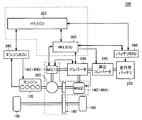
図1は、本発明の実施の形態に従う内燃機関の制御装置を搭載したハイブリッド車両のブロック図である。 FIG. 1 is a block diagram of a hybrid vehicle equipped with a control device for an internal combustion engine according to an embodiment of the present invention.
図1を参照して、ハイブリッド車両100は、駆動源として、たとえばガソリンエンジン等の内燃機関(以下単にエンジンという)120と、モータジェネレータ(MG)140とを備える。なお、以下においては、説明の便宜上、モータジェネレータ140をモータ140Aとジェネレータ140B(あるいはモータジェネレータ140B)と表現する。ただしハイブリッド車両100の走行状態に応じて、モータ140Aがジェネレータとして機能したり、ジェネレータ140Bがモータとして機能したりする。このモータジェネレータがジェネレータとして機能する場合に回生制動が行なわれる。モータジェネレータがジェネレータとして機能するときには、車両の運動エネルギが電気エネルギに変換されて車両が減速される。
Referring to FIG. 1,
ハイブリッド車両100は、さらに、減速機180と、動力分割機構(たとえば、遊星歯車機構)200とを備える。減速機180はエンジン120やモータジェネレータ140で発生した動力を駆動輪160に伝達したり、駆動輪160の駆動をエンジン120やモータジェネレータ140に伝達したりする。動力分割機構200は、エンジン120の発生する動力を駆動輪160とジェネレータ140Bとの2経路に分配する。
このように減速機180と動力分割機構200とは、内燃機関および電動機の少なくとも一方からの駆動力を車輪に伝達する。つまり、減速機180と動力分割機構200とは本発明の内燃機関の制御装置が搭載される車両における「動力伝達部」を構成する。
Thus,
ハイブリッド車両100は、さらに、走行用バッテリ220と、インバータ240とを備える。走行用バッテリ220は、モータジェネレータ140を駆動するための電力を充電する。インバータ240は、走行用バッテリ220の直流電圧とモータ140Aおよびジェネレータ140Bの交流電圧とを変換しながら電流制御を行なう。
ハイブリッド車両100は、さらに、バッテリ制御ユニット(以下、バッテリECU(Electronic Control Unit)という)260と、エンジンECU280と、MG_ECU300と、HV_ECU320とを含む。
バッテリECU260は、走行用バッテリ220の充放電状態を管理制御する。エンジンECU280は、エンジン120の動作状態を制御する。MG_ECU300は、ハイブリッド車両100の状態に応じてモータジェネレータ140と、バッテリECU260と、インバータ240とを制御する。HV_ECU320は、バッテリECU260と、エンジンECU280と、MG_ECU300とを相互に管理制御する。そしてHV_ECU320はハイブリッド車両100が最も効率よく運行できるようにハイブリッドシステム全体を制御する。
Battery ECU 260 manages and controls the charge / discharge state of battery for traveling 220. Engine ECU 280 controls the operating state of
本実施の形態において走行用バッテリ220とインバータ240との間には昇圧コンバータ242が設けられている。これは、走行用バッテリ220の定格電圧が、モータ140Aやモータジェネレータ140Bの定格電圧よりも低いためである。走行用バッテリ220からモータ140Aやモータジェネレータ140Bに電力を供給するときには、昇圧コンバータ242で電圧を昇圧する。
In the present embodiment,
なお、図1においては各ECUを別構成としているが、2個以上のECUを統合して1つのECUとして構成してもよい。たとえば図1において破線の枠で示されるようにMG_ECU300とHV_ECU320とを統合して1つのECUとして構成してもよい。別の例として、たとえばエンジンECU280とMG_ECU300とHV_ECU320とを統合して1つのECUとして構成してもよい。 In FIG. 1, each ECU is configured separately, but two or more ECUs may be integrated and configured as one ECU. For example, MG_ECU 300 and HV_ECU 320 may be integrated into a single ECU as indicated by a broken line frame in FIG. As another example, engine ECU 280, MG_ECU 300, and HV_ECU 320 may be integrated into a single ECU, for example.
動力分割機構200は、エンジン120の動力を駆動輪160とモータジェネレータ140Bとの両方に振分けるために遊星歯車機構(プラネタリギヤ)が使用される。モータジェネレータ140Bの回転数を制御することにより、動力分割機構200は無段変速機としても機能する。エンジン120の回転力はプラネタリキャリア(C)に入力され、それがサンギヤ(S)によってモータジェネレータ140Bに、リングギヤ(R)によってモータおよび出力軸(駆動輪160側)に伝えられる。回転中のエンジン120を停止させるときには、エンジン120が回転しているので、この回転の運動エネルギをモータジェネレータ140Bで電気エネルギに変換して、エンジン120の回転数を低下させる。
The
ハイブリッド車両100においてエンジン120の始動時には、ジェネレータ140Bによりエンジン120のクランクシャフトを回転させる動作(クランキング)が行なわれる。
In the
発進時や低速走行時等であってエンジン120の効率が悪い場合には、モータジェネレータ140のモータ140Aのみによりハイブリッド車両100の走行を行なう。通常走行時には、たとえば動力分割機構200によりエンジン120の動力が2経路に分けられる。2分割された動力の一方により駆動輪160の直接駆動が行なわれ、他方によりジェネレータ140Bが駆動されてジェネレータ140Bは発電する。このときに発生する電力でモータ140Aを駆動して駆動輪160の駆動補助を行なう。
When the
また、高速走行時には、さらに走行用バッテリ220からの電力をモータ140Aに供給して、モータ140Aの出力を増大させて駆動輪160に対して駆動力の追加を行なう。
Further, during high-speed traveling, electric power from the traveling
一方、減速時には駆動輪160により従動するモータ140Aがジェネレータとして機能して回生発電を行ない、回収した電力を走行用バッテリ220に蓄える。なお、走行用バッテリ220の充電量が低下して充電が特に必要な場合には、エンジン120の出力を増加してジェネレータ140Bによる発電量を増やし走行用バッテリ220に対する充電量を増加させる。
On the other hand, at the time of deceleration,
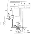
図2は、本実施の形態に従う内燃機関の制御装置により制御されるエンジンを示す概略構成図である。 FIG. 2 is a schematic configuration diagram showing an engine controlled by the control device for an internal combustion engine according to the present embodiment.
図2を参照して、エンジン120は、エアクリーナ102から吸入された空気とインジェクタ104から噴射される燃料との混合気を、燃焼室内で点火プラグ106により点火して燃焼させる内燃機関である。
Referring to FIG. 2,
混合気が燃焼すると、燃焼圧によりピストン108が押し下げられ、クランクシャフト110が回転する。燃焼後の混合気(排気ガス)は、三元触媒112により浄化された後、車外に排出される。エンジン120に吸入される空気の量は、スロットルバルブ114により調整される。
When the air-fuel mixture burns, the
クランクシャフト110が回転すると、チェーンあるいはベルト等で連結された吸気側および排気側のカムシャフト(図示せず)が回転させられる。そして、吸気側および排気側のカムシャフトの回転により、エンジン120の気筒の上部に設けられた吸気バルブ116および排気バルブ118の開閉が行なわれる。排気バルブ118が開くことにより、気筒内の燃焼後の排気ガスは、外部に排気される。そして、吸気バルブ116が開くことにより、気筒内に混合気が流入する。
When the
エンジン120の吸気側のカムシャフトには、さらにバルブタイミング可変機構122が設けられる。なお、排気側のカムシャフトにもバルブタイミング可変機構が設けられてもよい。バルブタイミング可変機構122は、吸気バルブ116の開閉のタイミングを可変とする機構である。
The cam timing on the intake side of the
エンジンECU280には、ノックセンサ294と、水温センサ302と、タイミングロータ290に対向して設けられたクランクポジションセンサ292と、スロットル開度センサ288と、車速センサ284と、イグニッションスイッチ286と、スロットルモータ296とが接続される。HV_ECU320には車速センサ284が接続される。
ノックセンサ294は、圧電素子により構成されている。ノックセンサ294は、エンジン120の振動により電圧を発生する。電圧の大きさは、振動の大きさと対応した大きさとなる。ノックセンサ294は、電圧を表す信号をエンジンECU280に送信する。
水温センサ302は、エンジン120のウォータージャケット内の冷却水の温度を検出し、検出結果を表す信号を、エンジンECU280に送信する。
タイミングロータ290は、クランクシャフト110に設けられており、クランクシャフト110と共に回転する。タイミングロータ290の外周には、予め定められた間隔で複数の突起が設けられている。クランクポジションセンサ292は、タイミングロータ290の突起に対向して設けられている。タイミングロータ290が回転すると、タイミングロータ290の突起と、クランクポジションセンサ292とのエアギャップが変化するため、クランクポジションセンサ292のコイル部を通過する磁束が増減し、コイル部に起電力が発生する。
The
クランクポジションセンサ292は、起電力を表す信号を、エンジンECU280に送信する。エンジンECU280は、クランクポジションセンサ292から送信された信号に基づいて、クランク角を検出する。
Crank position sensor 292 transmits a signal representing the electromotive force to
スロットル開度センサ288は、スロットル開度を検出し、検出結果を表す信号をエンジンECU280に送信する。車速センサ284は、車輪(図示せず)の回転数を検出し、検出結果を表す信号をエンジンECU280に送信する。エンジンECU280は、車輪の回転数から、車速を算出する。イグニッションスイッチ286は、エンジン120を始動させる際に、運転者によりオン操作される。
エンジンECU280は、各センサおよびイグニッションスイッチ286から送信された信号、エンジンECU280内のメモリ(図示せず)に記憶されたマップおよびプログラムに基づいて演算処理を行ない、エンジン120が所望の運転状態となるように、機器類を制御する。
制御装置310は本実施の形態に従う内燃機関の制御装置である。制御装置310はエンジンECU280と、HV_ECU320と、スロットルモータ296とを備える。スロットルモータ296はスロットルバルブ114を駆動してスロットルバルブ114の開度を変化させる。エンジンECU280およびHV_ECU320はスロットルモータ296にスロットル開度THを示す信号を送りスロットル開度を制御する。エンジンECU280およびHV_ECU320は本発明の内燃機関の制御装置における「始動制御部」に相当する。
エンジンECU280およびHV_ECU320はエンジン120の始動開始時点からの所定期間において、スロットル開度が制限値を超えず、かつ、単位時間あたりのスロットル開度の上昇率が所定の開度上昇率以下となるように、スロットルモータ296を制御する。これにより上記の所定期間内にはエンジンの出力パワーが大きく上昇しないよう制限される。
The
なお図1のハイブリッド車両100では、たとえば低速走行から通常走行に切換るときにエンジンが始動する。このときには運転者によるアクセルペダルの踏み込み量がある程度大きくなっている。しかし本実施の形態では、エンジン120の始動時におけるスロットル開度THはアクセルペダルの踏み込み量とは関係せずに制御されることになる。
In
このようにエンジン始動時におけるエンジン出力パワーが制限されることで、ハイブリッド車両100においてモータによる走行(以下「EV走行」とも称する)からエンジンによる走行(以下、「エンジン走行」とも称する)に切換る際に駆動力を滑らかに変化させることができる。よって本実施の形態によれば、たとえばエンジン始動時において運転者が体感するような振動を抑制することができる。また本実施の形態によればエンジンの始動時に吸入される空気量のばらつきを防ぐことができるので排気エミッションのばらつきを防ぐことができる。
By limiting the engine output power at the time of starting the engine in this way, the
なお、本実施の形態において「所定期間」とはクランキング時およびクランキング後にエンジン120が自立的に動作する期間を含むものとする。
In the present embodiment, the “predetermined period” includes a period during which
図3は、図1および図2のHV_ECU320の主要部の構成を示すブロック図である。
FIG. 3 is a block diagram showing a configuration of a main part of
図3を参照して、HV_ECU320は、要求トルク決定部321と、乗算部322と、加算部323と、レート制限処理部324と、エンジン回転数算出部325と、走行モード制御部326とを含む。
Referring to FIG. 3,
要求トルク決定部321はアクセル開度センサ298からアクセル開度Aに関する情報を受ける。アクセル開度センサ298は運転者のアクセルペダル(図示せず)の操作を検出するために設けられる。アクセル開度センサ298はアクセルペダルに対応して設けられ、運転者によるアクセルペダルの踏み込み量を検出する。アクセル開度センサ298はアクセルペダルの踏み込み量に応じた電圧を出力する。この出力電圧がアクセル開度Aの情報として要求トルク決定部321に送られる。
Requested
また、要求トルク決定部321は車速センサ284から図1のハイブリッド車両100の車速Vに関する情報を受ける。要求トルク決定部321はアクセル開度Aと車速Vと要求トルクTとが対応付けられたマップM1を予め記憶し、このマップM1を参照することで要求トルクTを決定する。
Requested
乗算部322は要求トルクTと車速Vとの積により走行パワーPを算出する(P=T×V)。加算部323は乗算部322から走行パワーPを受ける。また加算部323はバッテリECU260から走行用バッテリ220の充電状態を示す値SOCを受ける。加算部323はこれらの値を合わせて車両パワーPWを算出する。
The multiplying
要求トルク決定部321と、乗算部322と、加算部323とは、車両パワー算出部328を構成する。上述の説明を総括すれば、車両パワー算出部328は、少なくともアクセル開度に応じて、図1のハイブリッド車両100の駆動に必要な車両パワーPWを算出する。
The required
レート制限処理部324は車両パワーPWに応じて、図2のエンジン120への要求出力(エンジンパワーPe)を変化させる。レート制限処理部324は、エンジン120の始動開始時点から所定期間において、エンジンパワーPeの上昇を制限する制限処理を行なう。
The rate limiting
この「制限処理」をより詳細に説明すると、レート制限処理部324は単位時間あたりのエンジンパワーPeの上昇率が所定の出力上昇率以下となるようにエンジンパワーPeを変化させる。そしてレート制限処理部324は所定期間が経過するとこの制限処理を終了する。制限処理の終了後にはレート制限処理部324はエンジンパワーPeを車両パワーPWに追随させる。
The “limit process” will be described in more detail. The rate
なお、エンジンパワーPeを車両パワーPWに追随させる際にはエンジンパワーPeの増加に応じてモータのパワーは適切な変化率で減少する。これにより車両全体の駆動力に急激な変動を生じさせずにエンジンのトルクとモータのトルクとの分配比を滑らかに変化させてEV走行からエンジン走行に連続的に切換ることが可能になる。 When the engine power Pe is made to follow the vehicle power PW, the motor power decreases at an appropriate rate of change as the engine power Pe increases. As a result, it is possible to smoothly switch from EV traveling to engine traveling by smoothly changing the distribution ratio between the engine torque and the motor torque without causing rapid fluctuations in the driving force of the entire vehicle.
エンジン回転数算出部325は車両パワーPWとエンジン回転数Neとが対応付けられたマップM2を予め記憶し、このマップに基づいてエンジン回転数Neを算出する。エンジン回転数NeおよびエンジンパワーPeはエンジンECU280に送られる。
The engine
走行モード制御部326は車両パワーPWに応じてハイブリッド車両100の走行をエンジン走行とEV走行との間で切換える。これによりエンジンECU280またはMG_ECU300が制御される。
Traveling
このようにHV_ECU320は所定期間において、単位時間あたりのエンジンパワーPeの上昇率が所定の出力上昇率以下となるように、エンジンパワーPeを変化させる。すなわちHV_ECU320は本発明の内燃機関の制御装置における「出力制御部」に相当する。
Thus, the
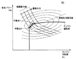
図4は、図3のマップM2の一例を示す図である。
図4を参照して、マップM2は横軸をエンジン回転数Neとし、縦軸を車両パワーPWとしたマップである。なおこのマップには等燃料消費率曲線と駆動力線とが併記される。エンジン120の駆動力が作動点Xにより表わされているときに、運転者がアクセルを踏んで駆動力を大きくしたい場合にはエンジン120の作動点はエンジン運転域上の作動点Xから作動点Yに移動する。これによりエンジン回転数Neが上昇するとともに車両パワーPW(すなわちエンジン120のトルク)が増大する。この状態で運転者がアクセルを戻すと作動点Yから作動点Xに戻る。
FIG. 4 is a diagram illustrating an example of the map M2 in FIG.
Referring to FIG. 4, a map M2 is a map in which the horizontal axis is the engine speed Ne and the vertical axis is the vehicle power PW. In this map, an equal fuel consumption rate curve and a driving force line are written together. When the driving force of the
図5は、図3のHV_ECU320で行なわれる処理を説明するフロー図である。
図5および図3を参照して、処理が開始されると、ステップS1において車両パワーPWが所定値以上であるか否かが判定される。ステップS1において車両パワーPWが所定値以上である場合(ステップS1においてYES)、処理はステップS2に移る。一方、ステップS1において車両パワーPWが所定値未満の場合(ステップS1においてNO)、処理はステップS5に移る。
FIG. 5 is a flowchart illustrating processing performed by
Referring to FIGS. 5 and 3, when the process is started, it is determined in step S1 whether vehicle power PW is equal to or greater than a predetermined value. If vehicle power PW is greater than or equal to a predetermined value in step S1 (YES in step S1), the process proceeds to step S2. On the other hand, when vehicle power PW is less than the predetermined value in step S1 (NO in step S1), the process proceeds to step S5.
ステップS5では走行モード制御部326によってハイブリッド車両100の走行はEV走行に設定される。
In step S5, the travel
一方、ステップS2の処理において、レート制限処理部324はエンジン始動中であるか否かを判定する。エンジン始動中である場合(ステップS2においてYES)、処理はステップS3に移る。一方、エンジン始動が完了している場合(ステップS2においてNO)、処理はステップS4に移る。
On the other hand, in the process of step S2, the rate limiting
たとえばレート制限処理部324はエンジン始動開始時点からの経過時間を計測する。経過時間が所定期間以内であればレート制限処理部324はエンジン始動中であると判定する。一方、経過時間が所定期間を超えればレート制限処理部324はエンジン始動完了であると判定する。
For example, the rate limiting
ステップS3においてレート制限処理部324は上述したエンジンパワーPeの上昇率を制限する。一方、ステップS4ではレート制限処理部324はエンジンパワーPeの上昇率を制限せず、エンジンパワーPeを車両パワーPWに追随させる。
In step S3, the rate limiting
ステップS3〜S5のいずれかの処理が終了すると、全体の処理は再びステップS1に戻る。 When any one of steps S3 to S5 is completed, the entire process returns to step S1 again.
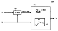
図6は、図1および図2のエンジンECU280の主要部の構成を示すブロック図である。
FIG. 6 is a block diagram showing a configuration of a main part of
図6を参照して、エンジンECU280は除算部281とスロットル開度算出部282とを含む。除算部281はHV_ECU320からエンジンパワーPeとエンジン回転数Neとを受ける。除算部281はエンジンパワーPeをエンジン回転数Neで割り算してエンジントルクTeを求める(Te=Pe/Ne)。
Referring to FIG. 6,
スロットル開度算出部282はエンジントルクTeとエンジン回転数Neとを受ける。スロットル開度算出部282はスロットル開度THとエンジントルクTeとエンジン回転数Neとが対応付けられたマップM3を予め記憶する。スロットル開度算出部282はマップM3に基づいてスロットル開度THを算出する。
The throttle
このようにエンジンECU280は、エンジンパワーPeに応じてスロットル開度THを求める。そしてエンジンECU280は、スロットルモータ296にスロットル開度THを指令する。つまり、エンジンECU280は本発明の内燃機関の制御装置における「開度指令部」に相当する。
Thus,
図7は、図2の制御装置310によるエンジン120の始動時の制御を説明する図である。
FIG. 7 is a diagram for explaining control at the time of starting the
図7を参照して、時刻t1以前では車両パワーPWは所定値P1以下である。よって図1のハイブリッド車両100は、時刻t1以前ではEV走行を行なう。また、時刻t1以前ではエンジンパワーPeは0である。
Referring to FIG. 7, vehicle power PW is equal to or less than predetermined value P1 before time t1. Therefore,
たとえばハイブリッド車両100を加速させることにより車両パワーPWが増加する。時刻t1において車両パワーPWが所定値P1に達すると図2の制御装置310によりエンジン120の始動が開始される。
For example, by accelerating
このとき、レート制限処理部324は所定期間(時刻t1から時刻t2までの期間)において、エンジンパワーPeの単位時間当たりの上昇率(Pa/t)を所定の出力上昇率(Pb/t)以下となるように制限する。
At this time, the rate limiting
エンジンECU280はエンジンパワーPeに応じてスロットル開度THを変化させる。よって、エンジンパワーPeの上昇率(Pa/t)を適切に設定することにより、スロットル開度THの単位時間あたりの上昇率(Ta/t)を所定の出力上昇率(Pb/t)に応じた所定の開度上昇率(Tb/t)以下に制限することができる。
また、本実施の形態では時刻t2の時点でスロットル開度THが制限値THlimを超えないように設定される。このようにスロットル開度THの上昇率(Ta/t)を制限することもエンジンパワーPeの上昇率(Pa/t)を適切に設定することにより可能となる。 In the present embodiment, the throttle opening TH is set so as not to exceed the limit value THlim at time t2. Thus, it is possible to limit the rate of increase (Ta / t) of the throttle opening TH by appropriately setting the rate of increase (Pa / t) of the engine power Pe.
時刻t2から図1のハイブリッド車両の走行はEV走行からエンジン走行に切換わる。時刻t2以後、レート制限処理部324はエンジンパワーPeを車両パワーPWに追随させる(Pe=PWとなる)ようエンジンパワーPeを上昇させる。これに応じてスロットル開度THも変化する。一方、モータのパワーはある適切な減少率で減少する。これにより、運転者が体感されるようなショックを生じさせずに、モータのパワーと車両パワーPWとが等しい状態からエンジンパワーPeと車両パワーPWとが等しい状態まで連続的にモータのパワーとエンジンパワーPeとを変化させることが可能になる。
The traveling of the hybrid vehicle in FIG. 1 is switched from EV traveling to engine traveling from time t2. After time t2, the rate limiting
図8は、エンジン始動時のアクセル開度およびエンジンパワーPeの変化を、本実施の形態と比較例とで比較する図である。なお比較例はエンジン始動期間におけるエンジンパワーの上昇を制限しない点で本実施の形態と異なる。比較例によればエンジン始動直後の応答性を高めること、すなわちエンジン始動から短期間で目標の車両パワーがエンジンから出力されることが期待される。 FIG. 8 is a diagram for comparing changes in the accelerator opening and the engine power Pe at the time of starting the engine between the present embodiment and the comparative example. The comparative example differs from the present embodiment in that the increase in engine power during the engine start period is not limited. According to the comparative example, it is expected that the responsiveness immediately after the engine is started, that is, the target vehicle power is output from the engine in a short period after the engine is started.
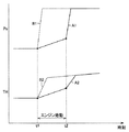
図8を参照して、時刻t1,t2は図7の時刻t1,t2にそれぞれ対応する。波形A1は本実施の形態によるエンジンパワーPeの変化を示す。波形B1は比較例によるエンジンパワーPeの変化を示す。波形A2は本実施の形態によるスロットル開度THの変化を示す。波形B2は比較例によるスロットル開度THの変化を示す。 Referring to FIG. 8, times t1 and t2 correspond to times t1 and t2 in FIG. A waveform A1 shows a change in the engine power Pe according to the present embodiment. A waveform B1 shows a change in the engine power Pe according to the comparative example. A waveform A2 shows a change in the throttle opening TH according to the present embodiment. A waveform B2 shows a change in the throttle opening TH according to the comparative example.
波形A1,B1を比較すると、時刻t1以後、比較例(波形B1)のほうが本実施の形態(波形A1)よりもエンジンパワーPeが急速に立ち上がる。このようなエンジンパワーの変化に応じて比較例のスロットル開度の上昇率(波形B2)は本実施の形態のスロットル開度の上昇率(波形A2)よりも大きくなる。 Comparing the waveforms A1 and B1, after time t1, the engine power Pe rises more rapidly in the comparative example (waveform B1) than in the present embodiment (waveform A1). In accordance with such a change in engine power, the rate of increase of the throttle opening (waveform B2) of the comparative example becomes larger than the rate of increase of the throttle opening (waveform A2) of the present embodiment.
しかしながら、比較例の場合には初回完爆時のエンジンの出力トルクは大きくなるものの、動力分割機構200や減速機180や駆動輪160の車軸(上述の「動力伝達部」)には、エンジンの出力トルクがいきなり伝達される。これにより動力伝達部にショックが生じるために運転者が振動等を感じることが起こり得る。しかしながらハイブリッド車両100の走行への効果は予想よりも小さいものとなる。
However, in the case of the comparative example, although the output torque of the engine at the time of the first complete explosion becomes large, the
さらに、比較例の場合、エンジン始動時のエンジンパワーPeは車両の走行状態等の条件によって異なる。その理由は、車両パワーPWがその時々の走行状態によって異なるためである。 Further, in the case of the comparative example, the engine power Pe at the time of starting the engine varies depending on conditions such as the running state of the vehicle. The reason is that the vehicle power PW differs depending on the running state at that time.
これにより比較例の場合にはエンジン始動時の吸気量が毎回異なる可能性がある。これにより比較例ではエンジン始動時における燃焼空燃比が毎回異なる可能性があるので排気エミッションがばらついたり、混合気の燃焼がうまくいかなかったりする。 As a result, in the case of the comparative example, there is a possibility that the intake amount at the time of starting the engine is different every time. As a result, in the comparative example, the combustion air-fuel ratio at the time of starting the engine may be different every time, so that the exhaust emission varies and the combustion of the air-fuel mixture fails.
本実施の形態では時刻t1から時刻t2の期間にはエンジンパワーPeの上昇が抑えられる。これにより、本実施の形態によれば動力伝達部に生じるショックを抑制できるので運転者が振動等を感じることを防ぐことができる。 In the present embodiment, an increase in engine power Pe is suppressed during the period from time t1 to time t2. Thereby, according to this Embodiment, since the shock which arises in a power transmission part can be suppressed, it can prevent that a driver | operator feels a vibration etc.
また、本実施の形態によれば、始動期間におけるスロットル開度THは制限値THlim以下であり、かつ、スロットル開度THの上昇率も制限される。このため本実施の形態ではエンジン始動時の吸気量のばらつきを低減できるので、燃焼空燃比のばらつきを低減できる。この結果、本実施の形態によれば、排気エミッションのばらつきを抑制できるとともに、エンジン始動時に混合気を確実に燃焼させることができる。 Further, according to the present embodiment, the throttle opening TH during the starting period is equal to or less than the limit value THlim, and the rate of increase of the throttle opening TH is also limited. For this reason, in the present embodiment, the variation in the intake air amount when starting the engine can be reduced, so that the variation in the combustion air-fuel ratio can be reduced. As a result, according to the present embodiment, variation in exhaust emission can be suppressed and the air-fuel mixture can be reliably burned when the engine is started.
なお、本実施の形態では車両の応答性が悪くなることが想定される。しかしながら本実施の形態では時刻t1から時刻t2の期間を最適に設定することで、たとえば運転者の違和感が生じないように車両の応答性を設定することが可能になる。 In this embodiment, it is assumed that the responsiveness of the vehicle is deteriorated. However, in the present embodiment, by setting the period from time t1 to time t2 optimally, it is possible to set the vehicle responsiveness so that, for example, the driver does not feel uncomfortable.
また本発明の内燃機関の制御装置を備える車両としては、本実施の形態に示されるようなハイブリッド車両100に限定されない。たとえば車両が一時的に停止した場合に、所定のエンジン停止条件の成立に応答してエンジンのアイドリングを強制的に止め、そのエンジン停止条件が成立しなくなった時点でエンジンを自動的にクランキングして再始動するエコラン車両にも本発明は適用可能である。
Further, the vehicle including the control device for an internal combustion engine of the present invention is not limited to the
今回開示された実施の形態はすべての点で例示であって制限的なものではないと考えられるべきである。本発明の範囲は上記した説明ではなくて特許請求の範囲によって示され、特許請求の範囲と均等の意味および範囲内でのすべての変更が含まれることが意図される。 The embodiment disclosed this time should be considered as illustrative in all points and not restrictive. The scope of the present invention is defined by the terms of the claims, rather than the description above, and is intended to include any modifications within the scope and meaning equivalent to the terms of the claims.
100 ハイブリッド車両、102 エアクリーナ、104 インジェクタ、106 点火プラグ、108 ピストン、110 クランクシャフト、112 三元触媒、114 スロットルバルブ、116 吸気バルブ、118 排気バルブ、120 エンジン、122 バルブタイミング可変機構、140 モータジェネレータ、160 駆動輪、180 減速機、200 動力分割機構、220 走行用バッテリ、240 インバータ、242 昇圧コンバータ、260 バッテリECU、280 エンジンECU、281 除算部、282 スロットル開度算出部、284 車速センサ、286 イグニッションスイッチ、288 スロットル開度センサ、290 タイミングロータ、292 クランクポジションセンサ、294 ノックセンサ、296 スロットルモータ、298 アクセル開度センサ、302 水温センサ、310 制御装置、320 HV_ECU、321 要求トルク決定部、322 乗算部、323 加算部、324 レート制限処理部、325 エンジン回転数算出部、326 走行モード制御部、328 車両パワー算出部、M1〜M3 マップ、S1〜S5 ステップ、X,Y 作動点。
DESCRIPTION OF
Claims (4)
前記自動車は、走行モードとして、前記電動機によって走行可能なEV走行モードと、前記内燃機関によって走行可能なエンジン走行モードとを有し、
前記内燃機関は、
前記内燃機関に吸入される空気の量を調整するスロットルバルブを有し、
前記制御装置は、
前記スロットルバルブを駆動して前記スロットルバルブの開度を変化させるスロットル駆動部と、
前記EV走行モードから前記エンジン走行モードへと前記走行モードが切換る場合に、前記内燃機関の始動開始時点から前記内燃機関が自立的に動作可能になるまでの期間において、前記開度が制限値を超えず、かつ、単位時間あたりの前記開度の上昇率が所定の開度上昇率以下となるように、前記スロットル駆動部を制御する始動制御部とを備え、
前記始動制御部は、前記内燃機関の前記始動開始時点から前記開度を上昇させる、内燃機関の制御装置。 A control device for an internal combustion engine mounted on an automobile together with an electric motor used as a drive source for driving wheels and operating as the drive source,
The automobile has, as a travel mode, an EV travel mode capable of traveling by the electric motor, and an engine travel mode capable of traveling by the internal combustion engine,
The internal combustion engine
A throttle valve for adjusting the amount of air sucked into the internal combustion engine;
The controller is
A throttle drive unit that drives the throttle valve to change the opening of the throttle valve;
When the travel mode is switched from the EV travel mode to the engine travel mode, the opening degree is a limit value during a period from the start of the start of the internal combustion engine until the internal combustion engine can operate independently. And a start control unit that controls the throttle drive unit so that the rate of increase of the opening per unit time is equal to or less than a predetermined rate of increase of the opening .
The start control unit is a control device for an internal combustion engine that increases the opening degree from the start start time of the internal combustion engine.
前記内燃機関の要求出力に応じて前記開度を求めて、前記スロットル駆動部に前記開度を指令する開度指令部と、
前記所定期間において、単位時間あたりの前記要求出力の上昇率が所定の出力上昇率以下となるように前記要求出力を変化させる制限処理を行なう出力制御部とを含む、請求項1に記載の内燃機関の制御装置。 The start control unit
An opening degree command unit for obtaining the opening degree according to a required output of the internal combustion engine and instructing the opening degree to the throttle drive unit;
2. The internal combustion engine according to claim 1, further comprising: an output control unit that performs a limiting process of changing the request output so that an increase rate of the request output per unit time is equal to or less than a predetermined output increase rate in the predetermined period. Engine control device.
少なくともアクセル開度に基づいて、前記自動車の駆動に必要な車両パワーを算出する車両パワー算出部と、
前記車両パワーが所定値を超えたことに応じて前記制限処理を開始して、前記所定期間が経過すると前記制限処理を終了して、前記制限処理の終了後は前記要求出力を前記車両パワーに追随させる制限処理部とを含む、請求項2に記載の内燃機関の制御装置。 The output control unit
A vehicle power calculation unit that calculates vehicle power required for driving the automobile based on at least an accelerator opening;
The limiting process is started in response to the vehicle power exceeding a predetermined value, and the limiting process is terminated when the predetermined period elapses, and the requested output is set to the vehicle power after the limiting process ends. The control device for an internal combustion engine according to claim 2, further comprising a restriction processing unit to be followed.
前記内燃機関および前記電動機の少なくとも一方からの駆動力を前記車輪に伝達する動力伝達部とをさらに備える、請求項1から請求項3のいずれか1項に記載の内燃機関の制御装置。 The car is
4. The control device for an internal combustion engine according to claim 1, further comprising a power transmission unit configured to transmit a driving force from at least one of the internal combustion engine and the electric motor to the wheels. 5.
Priority Applications (5)
| Application Number | Priority Date | Filing Date | Title |
|---|---|---|---|
| JP2006048908A JP4519085B2 (en) | 2006-02-24 | 2006-02-24 | Control device for internal combustion engine |
| PCT/IB2007/000440 WO2007096756A1 (en) | 2006-02-24 | 2007-02-23 | Control apparatus and method for internal combustion engine |
| US12/279,272 US7925417B2 (en) | 2006-02-24 | 2007-02-23 | Control apparatus and method for internal combustion engine |
| CN2007800065432A CN101389515B (en) | 2006-02-24 | 2007-02-23 | Control apparatus and method for internal combustion engine |
| EP07705645A EP1986902A1 (en) | 2006-02-24 | 2007-02-23 | Control apparatus and method for internal combustion engine |
Applications Claiming Priority (1)
| Application Number | Priority Date | Filing Date | Title |
|---|---|---|---|
| JP2006048908A JP4519085B2 (en) | 2006-02-24 | 2006-02-24 | Control device for internal combustion engine |
Publications (3)
| Publication Number | Publication Date |
|---|---|
| JP2007224848A JP2007224848A (en) | 2007-09-06 |
| JP2007224848A5 JP2007224848A5 (en) | 2008-05-29 |
| JP4519085B2 true JP4519085B2 (en) | 2010-08-04 |
Family
ID=38134933
Family Applications (1)
| Application Number | Title | Priority Date | Filing Date |
|---|---|---|---|
| JP2006048908A Expired - Lifetime JP4519085B2 (en) | 2006-02-24 | 2006-02-24 | Control device for internal combustion engine |
Country Status (5)
| Country | Link |
|---|---|
| US (1) | US7925417B2 (en) |
| EP (1) | EP1986902A1 (en) |
| JP (1) | JP4519085B2 (en) |
| CN (1) | CN101389515B (en) |
| WO (1) | WO2007096756A1 (en) |
Families Citing this family (17)
| Publication number | Priority date | Publication date | Assignee | Title |
|---|---|---|---|---|
| JP4229185B2 (en) * | 2007-01-12 | 2009-02-25 | トヨタ自動車株式会社 | Hybrid vehicle and control method thereof |
| JP4987551B2 (en) * | 2007-04-19 | 2012-07-25 | 富士通テン株式会社 | Eco-run system, control program, and eco-run status notification device |
| JP5530813B2 (en) * | 2010-06-04 | 2014-06-25 | トヨタ自動車株式会社 | Hybrid vehicle and control method thereof |
| JP5230709B2 (en) * | 2010-09-21 | 2013-07-10 | 日立オートモティブシステムズ株式会社 | Control device |
| JP2012091667A (en) * | 2010-10-27 | 2012-05-17 | Nissan Motor Co Ltd | Hybrid vehicle control device |
| JP5924003B2 (en) * | 2012-02-01 | 2016-05-25 | トヨタ自動車株式会社 | Vehicle throttle valve control device |
| EP2815945B1 (en) * | 2012-02-17 | 2019-10-09 | Toyota Jidosha Kabushiki Kaisha | Vehicle and vehicle control method |
| JP2014094627A (en) * | 2012-11-08 | 2014-05-22 | Toyota Motor Corp | Hybrid vehicle |
| US9611795B2 (en) * | 2012-12-04 | 2017-04-04 | Toyota Jidosha Kabushiki Kaisha | Control system of vehicle |
| KR101575536B1 (en) * | 2014-10-21 | 2015-12-07 | 현대자동차주식회사 | Method for controlling air control valve in diesel hybrid vehicle |
| CN105298712A (en) * | 2015-11-17 | 2016-02-03 | 奇瑞汽车股份有限公司 | Gasoline engine knock control method |
| JP7010068B2 (en) * | 2018-03-07 | 2022-01-26 | トヨタ自動車株式会社 | Hybrid car |
| CN110410221A (en) * | 2018-04-26 | 2019-11-05 | 陕西汽车集团有限责任公司 | The control method and device of vehicle accelerator slope |
| FR3104210B1 (en) * | 2019-12-09 | 2022-10-14 | Psa Automobiles Sa | METHOD FOR LIMITING THE QUANTITY OF POLLUTANTS DISCHARGED BY A HYBRID VEHICLE THERMAL ENGINE |
| JP7362227B2 (en) * | 2021-03-31 | 2023-10-17 | ダイハツ工業株式会社 | Hybrid vehicle control device |
| JP7657527B2 (en) | 2021-08-16 | 2025-04-07 | ダイハツ工業株式会社 | Control device for internal combustion engine |
| CN114909228B (en) * | 2022-05-27 | 2023-06-27 | 中国第一汽车股份有限公司 | Engine start control method and device, hybrid vehicle and storage medium |
Family Cites Families (17)
| Publication number | Priority date | Publication date | Assignee | Title |
|---|---|---|---|---|
| JPH08193531A (en) * | 1995-01-17 | 1996-07-30 | Nippondenso Co Ltd | Control system of hybrid vehicle |
| JP2000104599A (en) * | 1998-09-29 | 2000-04-11 | Nissan Motor Co Ltd | Hybrid vehicle control device |
| JP3577971B2 (en) | 1998-10-16 | 2004-10-20 | 日産自動車株式会社 | Vehicle start control device |
| JP2001010360A (en) | 1999-06-28 | 2001-01-16 | Suzuki Motor Corp | Hybrid powered vehicle |
| JP4304396B2 (en) | 2000-01-21 | 2009-07-29 | トヨタ自動車株式会社 | In-vehicle engine automatic stop / start device |
| JP4066616B2 (en) | 2000-08-02 | 2008-03-26 | トヨタ自動車株式会社 | Automatic start control device and power transmission state detection device for internal combustion engine |
| JP4075311B2 (en) | 2001-01-17 | 2008-04-16 | トヨタ自動車株式会社 | Start control device for internal combustion engine |
| JP4595242B2 (en) | 2001-05-17 | 2010-12-08 | トヨタ自動車株式会社 | Control device for vehicle engine |
| US6616569B2 (en) | 2001-06-04 | 2003-09-09 | General Motors Corporation | Torque control system for a hybrid vehicle with an automatic transmission |
| JP4480300B2 (en) * | 2001-06-22 | 2010-06-16 | 株式会社デンソー | Throttle control device for internal combustion engine |
| EP1375231B1 (en) * | 2002-06-19 | 2008-10-22 | Jtekt Corporation | Drive power distribution control method and device for four-wheel drive vehicle |
| JP3894159B2 (en) | 2003-05-20 | 2007-03-14 | トヨタ自動車株式会社 | POWER OUTPUT DEVICE, ITS CONTROL METHOD, AND AUTOMOBILE |
| US6868832B2 (en) * | 2003-07-09 | 2005-03-22 | Honda Motor Co., Ltd. | Electronic controlled fuel injection apparatus of internal combustion engine |
| JP3928624B2 (en) * | 2004-03-12 | 2007-06-13 | トヨタ自動車株式会社 | Control device for hybrid vehicle |
| JP4301066B2 (en) * | 2004-04-20 | 2009-07-22 | トヨタ自動車株式会社 | Automatic stop / start device for internal combustion engine and automobile equipped with the same |
| US7243011B2 (en) * | 2004-05-21 | 2007-07-10 | General Motors Corporation | Hybrid transmission launch algorithm |
| JP4155236B2 (en) * | 2004-07-09 | 2008-09-24 | トヨタ自動車株式会社 | Control device for vehicle drive device |
-
2006
- 2006-02-24 JP JP2006048908A patent/JP4519085B2/en not_active Expired - Lifetime
-
2007
- 2007-02-23 CN CN2007800065432A patent/CN101389515B/en not_active Expired - Fee Related
- 2007-02-23 EP EP07705645A patent/EP1986902A1/en not_active Withdrawn
- 2007-02-23 WO PCT/IB2007/000440 patent/WO2007096756A1/en not_active Ceased
- 2007-02-23 US US12/279,272 patent/US7925417B2/en active Active
Also Published As
| Publication number | Publication date |
|---|---|
| CN101389515B (en) | 2012-04-18 |
| US20090118980A1 (en) | 2009-05-07 |
| US7925417B2 (en) | 2011-04-12 |
| EP1986902A1 (en) | 2008-11-05 |
| CN101389515A (en) | 2009-03-18 |
| JP2007224848A (en) | 2007-09-06 |
| WO2007096756A1 (en) | 2007-08-30 |
Similar Documents
| Publication | Publication Date | Title |
|---|---|---|
| US7925417B2 (en) | Control apparatus and method for internal combustion engine | |
| JP4197038B2 (en) | Hybrid vehicle and control method thereof | |
| JP4175371B2 (en) | INTERNAL COMBUSTION ENGINE DEVICE, ITS CONTROL METHOD, AND POWER OUTPUT DEVICE | |
| JP5505509B2 (en) | Power train, control method and control apparatus for internal combustion engine | |
| JP4175361B2 (en) | Hybrid vehicle and control method thereof | |
| JP4301066B2 (en) | Automatic stop / start device for internal combustion engine and automobile equipped with the same | |
| JP4876953B2 (en) | Vehicle and control method thereof | |
| US7958868B2 (en) | Control device for vehicle | |
| WO2013042217A1 (en) | Vehicle and method for controlling vehicle | |
| JP2013154699A (en) | Control device for vehicle | |
| JP4100443B2 (en) | Control device for hybrid vehicle | |
| JP5617691B2 (en) | Vehicle and vehicle control method | |
| JP5331065B2 (en) | In-vehicle internal combustion engine controller | |
| JP2013112101A (en) | Hybrid vehicle | |
| JP3928597B2 (en) | DRIVE DEVICE, ITS CONTROL METHOD, AND AUTOMOBILE | |
| JP4069589B2 (en) | Control device for internal combustion engine | |
| JP2011235809A (en) | Device and method for controlling vehicles | |
| JP2005201197A (en) | Internal combustion engine control device, internal combustion engine control method, and automobile | |
| JP2004225623A (en) | Engine start control device and engine start control method | |
| JP2005273490A (en) | STARTING DEVICE AND STARTING METHOD FOR INTERNAL COMBUSTION ENGINE | |
| JP2007120382A (en) | POWER OUTPUT DEVICE, ITS CONTROL METHOD, AND VEHICLE | |
| JP2005110461A (en) | Control method of motor generator in parallel hybrid vehicle | |
| JP7814808B2 (en) | Control device | |
| JP2012153250A (en) | Vehicle control device | |
| JP6885292B2 (en) | Vehicle control device |
Legal Events
| Date | Code | Title | Description |
|---|---|---|---|
| A711 | Notification of change in applicant |
Free format text: JAPANESE INTERMEDIATE CODE: A711 Effective date: 20071115 |
|
| A521 | Request for written amendment filed |
Free format text: JAPANESE INTERMEDIATE CODE: A821 Effective date: 20071115 |
|
| A521 | Request for written amendment filed |
Free format text: JAPANESE INTERMEDIATE CODE: A523 Effective date: 20080416 |
|
| A621 | Written request for application examination |
Free format text: JAPANESE INTERMEDIATE CODE: A621 Effective date: 20080416 |
|
| A977 | Report on retrieval |
Free format text: JAPANESE INTERMEDIATE CODE: A971007 Effective date: 20090907 |
|
| A131 | Notification of reasons for refusal |
Free format text: JAPANESE INTERMEDIATE CODE: A131 Effective date: 20090915 |
|
| A521 | Request for written amendment filed |
Free format text: JAPANESE INTERMEDIATE CODE: A523 Effective date: 20091113 |
|
| TRDD | Decision of grant or rejection written | ||
| A01 | Written decision to grant a patent or to grant a registration (utility model) |
Free format text: JAPANESE INTERMEDIATE CODE: A01 Effective date: 20100511 |
|
| A01 | Written decision to grant a patent or to grant a registration (utility model) |
Free format text: JAPANESE INTERMEDIATE CODE: A01 |
|
| A61 | First payment of annual fees (during grant procedure) |
Free format text: JAPANESE INTERMEDIATE CODE: A61 Effective date: 20100518 |
|
| FPAY | Renewal fee payment (event date is renewal date of database) |
Free format text: PAYMENT UNTIL: 20130528 Year of fee payment: 3 |
|
| R151 | Written notification of patent or utility model registration |
Ref document number: 4519085 Country of ref document: JP Free format text: JAPANESE INTERMEDIATE CODE: R151 |
|
| FPAY | Renewal fee payment (event date is renewal date of database) |
Free format text: PAYMENT UNTIL: 20140528 Year of fee payment: 4 |
|
| R250 | Receipt of annual fees |
Free format text: JAPANESE INTERMEDIATE CODE: R250 |
|
| R250 | Receipt of annual fees |
Free format text: JAPANESE INTERMEDIATE CODE: R250 |
|
| R250 | Receipt of annual fees |
Free format text: JAPANESE INTERMEDIATE CODE: R250 |
|
| R250 | Receipt of annual fees |
Free format text: JAPANESE INTERMEDIATE CODE: R250 |
|
| R250 | Receipt of annual fees |
Free format text: JAPANESE INTERMEDIATE CODE: R250 |
|
| R250 | Receipt of annual fees |
Free format text: JAPANESE INTERMEDIATE CODE: R250 |
|
| R250 | Receipt of annual fees |
Free format text: JAPANESE INTERMEDIATE CODE: R250 |
|
| R250 | Receipt of annual fees |
Free format text: JAPANESE INTERMEDIATE CODE: R250 |
|
| R250 | Receipt of annual fees |
Free format text: JAPANESE INTERMEDIATE CODE: R250 |
|
| R250 | Receipt of annual fees |
Free format text: JAPANESE INTERMEDIATE CODE: R250 |
|
| R250 | Receipt of annual fees |
Free format text: JAPANESE INTERMEDIATE CODE: R250 |
|
| R250 | Receipt of annual fees |
Free format text: JAPANESE INTERMEDIATE CODE: R250 |
|
| R250 | Receipt of annual fees |
Free format text: JAPANESE INTERMEDIATE CODE: R250 |