JP2012153250A - Vehicle control device - Google Patents
Vehicle control device Download PDFInfo
- Publication number
- JP2012153250A JP2012153250A JP2011013948A JP2011013948A JP2012153250A JP 2012153250 A JP2012153250 A JP 2012153250A JP 2011013948 A JP2011013948 A JP 2011013948A JP 2011013948 A JP2011013948 A JP 2011013948A JP 2012153250 A JP2012153250 A JP 2012153250A
- Authority
- JP
- Japan
- Prior art keywords
- engine
- motor generator
- power
- torque
- output
- Prior art date
- Legal status (The legal status is an assumption and is not a legal conclusion. Google has not performed a legal analysis and makes no representation as to the accuracy of the status listed.)
- Withdrawn
Links
Images


Classifications
-
- Y—GENERAL TAGGING OF NEW TECHNOLOGICAL DEVELOPMENTS; GENERAL TAGGING OF CROSS-SECTIONAL TECHNOLOGIES SPANNING OVER SEVERAL SECTIONS OF THE IPC; TECHNICAL SUBJECTS COVERED BY FORMER USPC CROSS-REFERENCE ART COLLECTIONS [XRACs] AND DIGESTS
- Y02—TECHNOLOGIES OR APPLICATIONS FOR MITIGATION OR ADAPTATION AGAINST CLIMATE CHANGE
- Y02T—CLIMATE CHANGE MITIGATION TECHNOLOGIES RELATED TO TRANSPORTATION
- Y02T10/00—Road transport of goods or passengers
- Y02T10/60—Other road transportation technologies with climate change mitigation effect
- Y02T10/62—Hybrid vehicles
Abstract
Description
本発明は、車両の制御装置に関し、特に、ギヤを介してエンジンに連結された電動モータが搭載された車両の制御装置に関する。 The present invention relates to a vehicle control device, and more particularly, to a vehicle control device equipped with an electric motor connected to an engine via a gear.
エンジンおよび電動モータを駆動源として搭載したハイブリッド車が知られている。このようなハイブリッド車では、電動モータによってエンジンをアシストしたり、電動モータのみを駆動源として用いて走行することが可能である。エンジンと電動モータとは、たとえばプラネタリギヤセットを介して連結される。一例として、エンジンの出力軸がプラネタリキャリヤに接続され、電動モータの出力軸がリングギヤに接続される。サンギヤには発電機が接続される。 Hybrid vehicles equipped with an engine and an electric motor as drive sources are known. In such a hybrid vehicle, it is possible to assist the engine with an electric motor or to travel using only the electric motor as a drive source. The engine and the electric motor are connected through, for example, a planetary gear set. As an example, the output shaft of the engine is connected to the planetary carrier, and the output shaft of the electric motor is connected to the ring gear. A generator is connected to the sun gear.
プラネタリギヤセットを用いてエンジンと電動モータとを連結した場合、たとえば電動モータの出力トルクが零である状態では、エンジンと電動モータとを連結するギヤの間で隙間が生じ得る。ギヤの間に隙間がある状態でエンジンの出力トルクが変動すると、ギヤの歯同士が衝突することによって音が発生し得る。このような音の発生を抑制すべく、特開2009−173125号公報(特許文献1)は、第0041段落等において、モータのトルク指令の絶対値がしきい値以下のときには、燃費優先動作ラインに比べて回転数が大きくなるように設定された異音抑制動作ラインに基いてエンジンの運転ポイントとしての目標回転数と目標トルクとを設定することを開示する。 When the engine and the electric motor are connected using the planetary gear set, for example, when the output torque of the electric motor is zero, a gap may be generated between the gears connecting the engine and the electric motor. If the engine output torque fluctuates with a gap between the gears, the gear teeth may collide with each other to generate sound. In order to suppress the generation of such a sound, Japanese Patent Application Laid-Open No. 2009-173125 (Patent Document 1) describes a fuel consumption priority operation line when the absolute value of the motor torque command is equal to or less than a threshold value in the paragraph 0041 and the like. It is disclosed that the target rotational speed and the target torque are set as the engine operating point based on the abnormal noise suppression operation line set so that the rotational speed becomes larger than the above.
特開2009−173125号公報においては、電動モータのトルクが零付近となってから、すなわち音が発生し得る状況になってから、音の発生を抑制すべくエンジン回転数が増大される。したがって、エンジン回転数が増大するまでの間に音が発生し得る。運転者に与える不快感を考慮すると、音の発生を未然に防ぐことが好ましい。 In Japanese Patent Application Laid-Open No. 2009-173125, after the torque of the electric motor becomes close to zero, that is, after a situation where sound can be generated, the engine speed is increased to suppress the generation of sound. Therefore, sound can be generated before the engine speed increases. Considering the discomfort given to the driver, it is preferable to prevent the generation of sound.
本発明は、上述の課題を解決するためになされたものであって、その目的は、音の発生を未然に防ぐことである。 The present invention has been made to solve the above-described problems, and an object thereof is to prevent the generation of sound.
エンジンと、電動モータと、エンジンと電動モータとを連結するギヤと、エンジンによって駆動されて発電する発電機と、発電機が発電した電力を蓄える蓄電装置とが搭載された車両の制御装置は、蓄電装置の残存容量を検出するための手段と、蓄電装置の残存容量が予め定められたしきい値より大きいと、エンジンの出力軸回転数が増大するように制御するための制御手段とを備える。 A vehicle control device equipped with an engine, an electric motor, a gear that connects the engine and the electric motor, a generator that is driven by the engine to generate electric power, and a power storage device that stores electric power generated by the generator, Means for detecting the remaining capacity of the power storage device, and control means for controlling the output shaft speed of the engine to increase when the remaining capacity of the power storage device is greater than a predetermined threshold value. .
この構成によると、蓄電装置の残存容量が予め定められたしきい値より大きいと、エンジンの出力軸回転数が増大される。蓄電装置の残存容量が大きい状態では、必要な発電量が小さい。したがって、発電機による発電量を低減すべく、発電機を駆動するために用いられるトルク、すなわちエンジンの出力トルクが低減される。その結果、たとえば、エンジンの出力トルクを打ち消すために電動モータが出力すべきトルクが小さくなる(零に近づく)ことが予測される。そこで、蓄電装置の残存容量が予め定められたしきい値より大きいと、エンジンの出力軸回転数が増大される。これにより、電動モータの出力トルクが零に近づく前に、エンジンの出力軸回転数を増大することができる。そのため、ギヤから音が発生する前に、エンジンの出力軸回転数を増大することができる。エンジンの出力軸回転数が大きい場合は、小さい場合に比べてエンジンの出力トルクの変動が少ない。よって、エンジンと電動モータとの間に設けられたギヤの歯同士が衝突することが抑制される。その結果、音の発生を未然に防ぐことができる。 According to this configuration, when the remaining capacity of the power storage device is larger than a predetermined threshold value, the output shaft speed of the engine is increased. In a state where the remaining capacity of the power storage device is large, the required power generation amount is small. Therefore, in order to reduce the amount of power generated by the generator, the torque used to drive the generator, that is, the output torque of the engine is reduced. As a result, for example, it is predicted that the torque that should be output by the electric motor in order to cancel the output torque of the engine will be small (approaching zero). Therefore, when the remaining capacity of the power storage device is larger than a predetermined threshold value, the engine output shaft speed is increased. As a result, the output shaft speed of the engine can be increased before the output torque of the electric motor approaches zero. Therefore, it is possible to increase the engine output shaft speed before the sound is generated from the gear. When the engine output shaft speed is large, the engine output torque varies less than when the engine output shaft speed is small. Therefore, it is suppressed that the gear teeth provided between the engine and the electric motor collide with each other. As a result, generation of sound can be prevented beforehand.
以下、図面を参照しつつ、本発明の実施の形態について説明する。以下の説明では、同一の部品には同一の符号を付してある。それらの名称および機能も同一である。したがって、それらについての詳細な説明は繰返さない。 Hereinafter, embodiments of the present invention will be described with reference to the drawings. In the following description, the same parts are denoted by the same reference numerals. Their names and functions are also the same. Therefore, detailed description thereof will not be repeated.
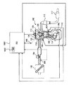
図1を参照して、本実施の形態に係る制御装置を搭載したハイブリッド車のパワートレーンについて説明する。なお、本実施の形態に係る制御装置は、たとえば、ECU(Electronic Control Unit)1000のROM(Read Only Memory)1002に記録されたプログラムをECU1000が実行することにより実現される。
With reference to FIG. 1, a power train of a hybrid vehicle equipped with the control device according to the present embodiment will be described. Note that the control device according to the present embodiment is realized, for example, when
図1に示すように、パワートレーンは、エンジン100と、第1モータジェネレータ(MG1)200と、これらエンジン100と第1モータジェネレータ200との間でトルクを合成もしくは分配する動力分割機構300と、第2モータジェネレータ(MG2)400と、変速機500とを主体として構成されている。
As shown in FIG. 1, the power train includes an
エンジン100は、燃料を燃焼させて動力を出力する公知の動力装置であって、スロットル開度(吸気量)や燃料供給量、点火時期などの運転状態を電気的に制御できるように構成されている。その制御は、例えば、マイクロコンピュータを主体とするECU1000によって行なわれる。
The
図2を参照して、エンジン100には、エアクリーナ102から空気が吸入される。吸入空気量は、スロットルバルブ104により調整される。スロットルバルブ104はモータにより駆動される電子スロットルバルブである。
Referring to FIG. 2,
空気は、シリンダ106(燃焼室)において燃料と混合される。シリンダ106には、インジェクタ108から燃料が直接噴射される。すなわち、インジェクタ108の噴射孔はシリンダ106内に設けられている。燃料は、シリンダ106の吸気側(空気が導入される側)から噴射される。
Air is mixed with fuel in the cylinder 106 (combustion chamber). Fuel is directly injected into the
燃料は吸気行程において噴射される。なお、燃料が噴射される時期は、吸気行程に限ら
ない。また、本実施の形態においては、インジェクタ108の噴射孔がシリンダ106内に設けられた直噴エンジンとしてエンジン100を説明するが、直噴用のインジェクタ108に加えて、ポート噴射用のインジェクタを設けてもよい。さらに、ポート噴射用のインジェクタのみを設けるようにしてもよい。
Fuel is injected during the intake stroke. Note that the timing of fuel injection is not limited to the intake stroke. In this embodiment, the
シリンダ106内の混合気は、点火プラグ110により着火され、燃焼する。燃焼後の混合気、すなわち排気ガスは、三元触媒112により浄化された後、車外に排出される。混合気の燃焼によりピストン114が押し下げられ、クランクシャフト116が回転する。
The air-fuel mixture in the
シリンダ106の頭頂部には、吸気バルブ118および排気バルブ120が設けられる。シリンダ106に導入される空気の量および時期は吸気バルブ118により制御される。シリンダ106から排出される排気ガスの量および時期は排気バルブ120により制御される。吸気バルブ118はカム122により駆動される。排気バルブ120はカム124により駆動される。
An
吸気バルブ118は、VVT(Variable Valve Timing)機構126により、開閉タイミング(位相)が変更される。なお、排気バルブ120の開閉タイミングを変更するようにしてもよい。
The
本実施の形態においては、カム122が設けられたカムシャフト(図示せず)がVVT機構126により回転されることにより、吸気バルブ118の開閉タイミングが制御される。なお、開閉タイミングを制御する方法はこれに限らない。
In the present embodiment, the camshaft (not shown) provided with the
エンジン100は、ECU1000により制御される。ECU1000は、エンジン100が所望の運転状態になるように、スロットル開度、点火時期、燃料噴射時期、燃料噴射量、吸気バルブ118の開閉タイミングを制御する。ECU1000には、カム角センサ800、クランク角センサ802、水温センサ804、エアフローメータ806から信号が入力される。
カム角センサ800は、カムの位置を表す信号を出力する。クランク角センサ802は、クランクシャフト116の回転数(エンジン回転数)NEおよびクランクシャフト116の回転角度を表す信号を出力する。水温センサ804は、エンジン100の冷却水の温度(以下、水温とも記載する)を表す信号を出力する。エアフローメータ806は、エンジン100に吸入される空気量KL表す信号を出力する。
The
ECU1000は、これらのセンサから入力された信号、ROM1002に記憶されたマップおよびプログラムに基づいて、エンジン100を制御する。
図1に戻って、第1モータジェネレータ200は、一例として三相交流回転電機である。第1モータジェネレータ200は、主に発電機として用いられる。第1モータジェネレータ200がモータとして用いられる場合もある。第1モータジェネレータ200は、インバータ210を介してバッテリなどの蓄電装置700に接続されている。蓄電装置700は、第1モータジェネレータ200により発電された電力を蓄える。インバータ210を制御することにより、第1モータジェネレータ200の出力トルクあるいは回生トルクを適宜に設定するようになっている。その制御は、ECU1000によって行なわれる。なお、第1モータジェネレータ200のステータ(図示せず)は固定されており、回転しないようになっている。
Returning to FIG. 1, the
一例として、第1モータジェネレータ200の回生トルク、すなわち発電電力は、蓄電装置700の残存容量(SOC: State Of Charge)に応じて定められる。たとえば、残存容量が大きいほど、発電電力が低下するように定められる。発電電力を低下するするために、第1モータジェネレータ200の回生トルクが低下される。
As an example, the regenerative torque of
動力分割機構300は、外歯歯車であるサンギヤ(S)301と、そのサンギヤ(S)301に対して同心円上に配置された内歯歯車であるリングギヤ(R)302と、これらサンギヤ(S)301とリングギヤ(R)302とに噛合しているピニオンギヤを自転かつ公転自在に保持しているキャリヤ(C)303とを三つの回転要素として差動作用を生じる公知の歯車機構である。エンジン100の出力軸がダンパを介して第1の回転要素であるキャリヤ(C)303に連結されている。言い換えれば、キャリヤ(C)303が入力要素となっている。
The
これに対して第2の回転要素であるサンギヤ(S)301に第1モータジェネレータ200のロータ(図示せず)が連結されている。したがってサンギヤ(S)301がいわゆる反力要素となっており、また第3の回転要素であるリングギヤ(R)302が出力要素となっている。そして、そのリングギヤ(R)302が、駆動輪(図示せず)に連結された出力軸600に連結されている。出力軸600の回転数は、出力軸回転数センサ602により検出され、出力軸回転数を表わす信号がECU1000に入力される。
On the other hand, the rotor (not shown) of the
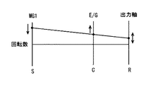
図3に、動力分割機構300の共線図を示す。図3に示すように、キャリヤ(C)303に入力されるエンジン100の出力するトルクに対して、第1モータジェネレータ200による反力トルクをサンギヤ(S)301に入力すると、これらのトルクを加減算した大きさのトルクが、出力要素となっているリングギヤ(R)302に現れる。その場合、第1モータジェネレータ200のロータがそのトルクによって回転し、第1モータジェネレータ200は発電機として機能する。また、リングギヤ(R)302の回転数(出力回転数)を一定とした場合、第1モータジェネレータ200の回転数を大小に変化させることにより、エンジン100の回転数を連続的に(無段階に)変化させることができる。すなわち、エンジン100の回転数を例えば燃費が最もよい回転数に設定する制御を、第1モータジェネレータ200を制御することによって行なうことができる。その制御は、ECU1000によって行なわれる。
FIG. 3 shows an alignment chart of the
走行中にエンジン100を停止させていれば、第1モータジェネレータ200が逆回転しており、その状態から第1モータジェネレータ200を電動機として機能させて正回転方向にトルクを出力させると、キャリヤ(C)303に連結されているエンジン100にこれを正回転させる方向のトルクが作用し、第1モータジェネレータ200によってエンジン100を始動(モータリングもしくはクランキング)することができる。その場合、出力軸600にはその回転を止める方向のトルクが作用する。したがって走行のための駆動トルクは、第2モータジェネレータ400の出力するトルクを制御することにより維持でき、同時にエンジン100の始動を円滑におこなうことができる。なお、この種のハイブリッド形式は、機械分配式あるいはスプリットタイプと称されている。
If the
図1に戻って、第2モータジェネレータ400は、一例として三相交流回転電機である。第2モータジェネレータ400は、主にモータとして用いられる。第2モータジェネレータ400が発電機として用いられる場合もある。第2モータジェネレータ400は、インバータ310を介してバッテリなどの蓄電装置700に接続されている。蓄電装置700は、回生制動時などにおいて第2モータジェネレータ400により発電された電力を蓄える。インバータ310を制御することにより、力行および回生ならびにそれぞれの場合におけるトルクを制御するように構成されている。なお、第2モータジェネレータ400のステータ(図示せず)は固定されており、回転しないようになっている。
Returning to FIG. 1, the
変速機500は、一組のラビニョ型遊星歯車機構によって構成されている。それぞれ外歯歯車である第1サンギヤ(S1)510と第2サンギヤ(S2)520とが設けられており、その第1サンギヤ(S1)510に第1のピニオンギヤ531が噛合するとともに、その第1のピニオンギヤ531が第2のピニオンギヤ532に噛合し、その第2のピニオンギヤ532が各サンギヤ510,520と同心円上に配置されたリングギヤ(R)540に噛合している。
The
なお、各ピニオンギヤ531,532は、キャリヤ(C)550によって自転かつ公転自在に保持されている。また、第2サンギヤ(S2)520が第2のピニオンギヤ532に噛合している。したがって第1サンギヤ(S1)510とリングギヤ(R)540とは、各ピニオンギヤ531,532と共にダブルピニオン型遊星歯車機構に相当する機構を構成し、また第2サンギヤ(S2)520とリングギヤ(R)540とは、第2のピニオンギヤ532と共にシングルピニオン型遊星歯車機構に相当する機構を構成している。 The pinion gears 531 and 532 are held by a carrier (C) 550 so as to rotate and revolve freely. Further, the second sun gear (S 2) 520 is engaged with the second pinion gear 532. Therefore, the first sun gear (S1) 510 and the ring gear (R) 540 constitute a mechanism corresponding to a double pinion type planetary gear mechanism together with the pinion gears 531 and 532, and the second sun gear (S2) 520 and the ring gear (R). 540 and the second pinion gear 532 constitute a mechanism corresponding to a single pinion type planetary gear mechanism.
さらに、変速機500には、第1サンギヤ(S1)510を選択的に固定するB1ブレーキ561と、リングギヤ(R)540を選択的に固定するB2ブレーキ562とが設けられている。これらのブレーキ561,562は摩擦力によって係合力を生じるいわゆる摩擦係合要素であり、多板形式の係合装置あるいはバンド形式の係合装置を採用することができる。そして、これらのブレーキ561,562は、油圧による係合力に応じてそのトルク容量が連続的に変化するように構成されている。さらに、第2サンギヤ(S2)520に前述した第2モータジェネレータ400が連結される。キャリヤ(C)550が出力軸600に連結される。
Further, the
したがって、上記の変速機500は、第2サンギヤ(S2)520がいわゆる入力要素であり、またキャリヤ(C)550が出力要素となっており、B1ブレーキ561を係合させることにより変速比が“1”より大きい高速段が設定される。B1ブレーキ561に替えてB2ブレーキ562を係合させることにより、高速段より変速比の大きい低速段が設定される。
Therefore, in the above-described
この各変速段の間での変速は、車速や要求駆動力(もしくはアクセル開度)などの走行状態に基づいて実行される。より具体的には、変速段領域を予めマップ(変速線図)として定めておき、検出された運転状態に応じていずれかの変速段を設定するように制御される。 The speed change between the respective speeds is executed based on a traveling state such as a vehicle speed and a required driving force (or accelerator opening). More specifically, the shift speed region is determined in advance as a map (shift diagram), and control is performed so as to set one of the shift speeds according to the detected driving state.
図4に、変速機500の共線図を示す。図4に示すように、B2ブレーキ562によってリングギヤ(R)540を固定すれば、低速段Lが設定され、第2モータジェネレータ400の出力したトルクが変速比に応じて増幅されて出力軸600に付加される。これに対してB1ブレーキ561によって第1サンギヤ(S1)510を固定すれば、低速段Lより変速比の小さい高速段Hが設定される。この高速段Hにおける変速比も“1”より大きいので、第2モータジェネレータ400の出力したトルクがその変速比に応じて増大させられて出力軸600に付加される。
FIG. 4 shows an alignment chart of the
なお、各変速段L,Hが定常的に設定されている状態では、出力軸600に付加されるトルクは、第2モータジェネレータ400の出力トルクを変速比に応じて増大させたトルクとなるが、変速過渡状態では各ブレーキ561,562でのトルク容量や回転数変化に伴う慣性トルクなどの影響を受けたトルクとなる。また、出力軸600に付加されるトルクは、第2モータジェネレータ400の駆動状態では、正トルクとなり、被駆動状態では負トルクとなる。
It should be noted that, in a state where the respective gear stages L and H are constantly set, the torque applied to the
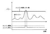
図5に示すように、ハイブリッド車の走行パワーがエンジン始動しきい値より小さいと、第2モータジェネレータ400の駆動力のみを用いてハイブリッド車が走行する。
As shown in FIG. 5, when the traveling power of the hybrid vehicle is smaller than the engine start threshold, the hybrid vehicle travels using only the driving force of
一方、ハイブリッド車の走行パワーがエンジン始動しきい値以上になると、エンジン100が駆動される。これにより、第2モータジェネレータ400の駆動力に加えて、もしくは代わりに、エンジン100の駆動力を用いてハイブリッド車が走行する。また、エンジン100の駆動力を用いて第1モータジェネレータ200が発電した電力が第2モータジェネレータ400に直接供給される。
On the other hand, when the traveling power of the hybrid vehicle exceeds the engine start threshold value,
走行パワーは、たとえば、ドライバにより操作されるアクセルペダルの開度(アクセル開度)および車速などをパラメータに有するマップに従ってECU1000により算出される。すなわち、本実施の形態において、ハイブリッド車の走行パワーは、運転者が要求するパワーを表わす。なお、走行パワーを算出する方法はこれに限らない。なお、本実施の形態において、パワーの単位はkW(キロワット)である。
The traveling power is calculated by
ハイブリッド車は、走行パワーを、エンジン100と第2モータジェネレータ400とで分担して実現するように制御される。たとえば、第1モータジェネレータ200が発電しない場合であれば、エンジン100の出力パワーと第2モータジェネレータ400の出力パワーとの和が、走行パワーと略同じになるように制御される。したがって、エンジン100の出力パワーが零であると、第2モータジェネレータ400の出力パワーが、走行パワーと略同じになるように制御される。第2モータジェネレータ400の出力パワーが零であると、エンジン100の出力パワーが走行パワーと略同じになるように制御される。
The hybrid vehicle is controlled so that traveling power is shared by
エンジン100を駆動する場合、たとえば、車速が高いほど、第2モータジェネレータ400の出力トルクが低下されて、走行パワーに対するエンジン100の出力パワーの比率が大きくされる。
When driving
一例として、車速が高い場合には、エンジン100が運転する一方で、第2モータジェネレータ400の出力トルクTMが零以下まで低下された状態で、ハイブリッド車が走行することもあり得る。すなわち、出力軸600に所望のトルクが伝達されるように、エンジン100から出力軸600に伝達されるトルクの一部を打ち消すように、第2モータジェネレータ400が負回転方向にトルクを出力して走行することもあり得る。
As an example, when the vehicle speed is high, the hybrid vehicle may travel while the
第1モータジェネレータ200が発電する場合、走行パワーに対してエンジン100が分担すべきパワーに、第1モータジェネレータ200によって発電される電力に相当するパワーを加算したパワーを出力するようにエンジン100が制御される。
When the
その他、蓄電装置700の残存容量が予め定められた下限値以下になった場合、第1モータジェネレータ200を駆動して発電し、蓄電装置700を充電するために、エンジン100が運転される。
In addition, when the remaining capacity of
エンジン100の出力パワーが第1モータジェネレータ200を駆動するためだけに用いられる場合は、発電される電力に相当するパワーとエンジン100の出力パワーと略同じである。なお、出力パワーの制御態様はこれらに限らない。
When the output power of
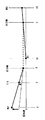
エンジン100の出力軸回転数(エンジン回転数)NEおよび出力トルクは、図6において燃費最適ラインまたは破線で示す異音抑制動作ラインに従って定められる。燃費最適ラインおよび異音抑制動作ラインは、エンジン回転数NEと出力トルクとの関係を示す。すなわち、燃費最適ラインおよび異音抑制動作ラインは、エンジン100の動作点を定める。燃費最適ラインおよび異音抑制動作ラインは、実験およびシミュレーションなどの結果に基づいて開発者により予め定められる。異音抑制動作ラインは、燃費最適ラインと比べて、同じ出力トルクを実現するときのエンジン回転数NEが高い。
The output shaft rotational speed (engine rotational speed) NE and output torque of
エンジン100のエンジン回転数NEおよび出力トルクTEは、燃費最適ラインまたは異音抑制動作ラインと、運転者の操作に応じて定められたエンジン100の出力パワーを示す等パワー線との交点として定められる。すなわち、エンジン100のエンジン回転数NEは、燃費最適ライン上または異音抑制動作ライン上において、運転者の操作に応じて定められたエンジン100の出力パワーを実現する回転数である。
The engine speed NE and the output torque TE of the
燃費最適ラインは、燃費が最適になるように、実験およびシミュレーション等に基いて開発者により予め定められる。異音抑制動作ラインは、たとえば第2モータジェネレータ400の出力トルクTMが零付近である状態において、動力分割機構300または変速機500のギヤの歯同士が衝突することによる音の発生を、エンジン100の出力トルクTEの変動を小さくすることによって抑制するために用いられる。
The fuel efficiency optimal line is predetermined by the developer based on experiments and simulations so that the fuel efficiency is optimal. The abnormal noise suppression operation line, for example, generates sound due to the collision of gear teeth of the
すなわち、異音抑制動作ラインによって定められるエンジン回転数NEおよび出力トルクTEでエンジン100を駆動すると、エンジン100の出力トルクTEの変動が小さくなる。したがって、ギヤの歯同士が衝突することにより発生する音が低減される。異音抑制動作ラインは、このような機能を実現し得るように定められる。異音抑制動作ラインは、実験およびシミュレーション等に基いて開発者により予め定められる。
That is, when
本実施の形態では、一例として、第2モータジェネレータ400の出力トルクTMが、「−γ」から「γ」(「γ」は所定の正の値)までの範囲内である状態において、異音抑制動作ラインに従って定められたエンジン回転数NEおよび出力トルクTEでエンジン100が駆動される。すなわち、第2モータジェネレータ400の出力トルクTMが、零を含む所定範囲内である状態において、異音抑制動作ラインに従って定められたエンジン回転数NEおよび出力トルクTEでエンジン100が駆動される。
In the present embodiment, as an example, in the state where the output torque TM of the
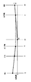
以下、図7に示すように、第1モータジェネレータ200により発電しながら、エンジン100を用いて車両が略一定の車速で走行する状態を想定する。さらに、そのような状態において、出力軸600に所望のトルクを伝達すべく、第2モータジェネレータ400の出力トルクTMが「−γ」よりも小さくなるように制御されていると想定する。すなわち、第2モータジェネレータ400が、図7において矢印で示す負回転方向に、絶対値が「γ」よりも大きいトルクを出力するように制御される。図7に示す状態では変速機500の変速段は高速段Hであると想定するが、低速段Lであってもよい。
Hereinafter, as shown in FIG. 7, a state is assumed in which a vehicle travels at a substantially constant vehicle
図7に示す運転状態におけるエンジン100の燃費最適ライン上の動作点を図8に示す。図8における「TE1」は、第2モータジェネレータ400の出力トルクが「−γ」と一致するときのエンジン100の出力トルクTEを示す。すなわち、エンジン100の出力トルクTEが「TE1」まで低下すると、出力軸600に伝達されるトルクを維持すべく、第2モータジェネレータ400の出力トルクTMの絶対値が「γ」まで低下される(出力トルクTMが「−γ」まで増大される)。
FIG. 8 shows operating points on the fuel efficiency optimum line of the
図8における「TE2」は、第2モータジェネレータ400の出力トルクTMが「γ」と一致するときのエンジン100の出力トルクTEを示す。すなわち、エンジン100の出力トルクTEが「TE2」まで低下すると、トルクの不足分を補い、所望のトルクを出力軸600に伝達すべく、第2モータジェネレータ400の出力トルクTMが正回転方向に「γ」まで増大される。
“TE2” in FIG. 8 indicates the output torque TE of the
図8に示す動作点にてエンジン100が運転している状態で、蓄電装置700の残存容量が増大すると、蓄電装置700の充電のために第1モータジェネレータ200が発電すべき電力は減少する。第1モータジェネレータ200が発電する電力を低減すべく、第1モータジェネレータ200のトルク(負回転方向のトルク)を低減すると、エンジン100の負荷が低減する。その結果、エンジン100が出力すべきパワーは、図9に示すように低減する。
If the remaining capacity of
低減後のパワーを実現すべく、エンジン100の出力トルクTEが「TE1」よりも小さくなると、第2モータジェネレータ400の出力トルクが「−γ」よりも零に近づき得る。この場合、動力分割機構300または変速機500のギヤの歯同士が衝突することによる音の発生を抑制すべく、エンジン100の動作点を燃費最適ラインから異音抑制動作ラインに移す必要がある。
If the output torque TE of the
図10に示すように、本実施の形態においては、エンジン100の出力トルクTEが「TE1」まで低下する前、すなわち第2モータジェネレータ400の出力トルクが「−γ」よりも大きくなる前に、エンジン100の動作点が燃費最適ラインから異音抑制動作ラインに移される。エンジン100の動作点が燃費最適ラインから異音抑制動作ラインに移った後、エンジン100の出力パワーが低下するように異音抑制動作ラインに沿ってエンジン100の動作点が変化される。
As shown in FIG. 10, in the present embodiment, before output torque TE of
以下、このような機能を実現するためのECU1000の構成について説明する。なお、ECU1000の機能はハードウェアにより実現してもよく、ソフトウェアにより実現してもよく、ハードウェアとソフトウェアとの協働により実現してもよい。
Hereinafter, a configuration of
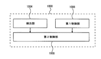
図11を参照して、ECU1000は、検出部1004と、第1制御部1006と、第2制御部1008とを備える。検出部1004は、蓄電装置700の残存容量を検出する。蓄電装置700の残存容量は、たとえば、蓄電装置700の電圧および電流に基いて算出される。残存容量を算出する方法には周知の一般的な技術を利用すればよいため、ここではその詳細な説明は繰り返さない。
Referring to FIG. 11,
第1制御部1006は、零を含む所定範囲(「−γ」から「γ」までの範囲)外のトルクを第2モータジェネレータ400が出力するように制御する。
The
第2制御部1008は、蓄電装置700の残存容量が予め定められたしきい値より大きいと、エンジン回転数NEが増大するように制御する。より具体的には、上記の所定範囲外のトルクを第2モータジェネレータ400が出力するように制御され、かつ蓄電装置700の残存容量がしきい値より大きいと、エンジン回転数NEが増大するように制御される。たとえば、図12に示すように、出力軸600の回転数(すなわち車速)を維持したまま、第1モータジェネレータ200の出力軸回転数を増大させることにより、エンジン回転数NEが増大するように制御される。
残存容量のしきい値は、実験およびシミュレーションなどの結果に基いて、開発者により予め設定される。たとえば、蓄電装置700の残存容量がしきい値まで増大したときのエンジン100の出力パワーと、燃費最適ラインとによって定まる出力トルクTEが、上述の「TE1」よりも大きくなるように、しきい値が定められる。しきい値を定める態様はこれに限定されない。
The threshold of the remaining capacity is set in advance by the developer based on results of experiments and simulations. For example, the threshold value is set so that output torque TE determined by the output power of
さらに、第2制御部1008は、エンジン回転数NEが増大した後、エンジン100のトルクTEが低下するように制御する。
Further,
図13を参照して、ECU1000が実行する処理について説明する。
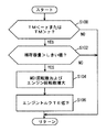
ステップ(以下、ステップをSと略す)100にて、「−γ」から「γ」までの範囲外のトルクを第2モータジェネレータ400が出力するように制御されているか否かが判断される。
Processing executed by
In step (hereinafter, step is abbreviated as S) 100, it is determined whether or not
「−γ」から「γ」までの範囲外のトルクを第2モータジェネレータ400が出力するように制御されていると(S100にてYES)、S102にて、蓄電装置700の残存容量がしきい値より大きいか否かが判断される。蓄電装置700の残存容量がしきい値より大きいと(S102にてYES)、S104にて、第1モータジェネレータ200の出力軸回転数を増大させることにより、エンジン回転数NEが増大される。エンジン100の動作点が異音抑制動作ライン上に位置するまでエンジン回転数NEが増大される。
If
その後、S106にて、異音抑制動作ラインに沿ってエンジン100の動作点が移動するように、エンジン100の出力トルクTEが低下される。しきい値まで増大した蓄電装置700の残存容量に基いて定められる出力パワーまでエンジン100の出力パワーが低下するように、出力トルクTEが低下される。
Thereafter, in S106, output torque TE of
以上のように、本実施の形態によれば、蓄電装置700の残存容量が予め定められたしきい値より大きいと、エンジン回転数NEが増大される。これにより、第2モータジェネレータ400の出力トルクTMが「−γ」よりも零に近づく前に、エンジン回転数NEを増大することができる。そのため、動力分割機構300または変速機500のギヤの歯同士が衝突することによる音が発生する前に、エンジン100の出力トルクTEの変動を小さくすべく、エンジン回転数NEを増大することができる。その結果、音の発生を未然に防ぐことができる。
As described above, according to the present embodiment, engine speed NE is increased when the remaining capacity of
今回開示された実施の形態は、すべての点で例示であって制限的なものではないと考えられるべきである。本発明の範囲は上記した説明ではなくて特許請求の範囲によって示され、特許請求の範囲と均等の意味および範囲内でのすべての変更が含まれることが意図される。 The embodiment disclosed this time should be considered as illustrative in all points and not restrictive. The scope of the present invention is defined by the terms of the claims, rather than the description above, and is intended to include any modifications within the scope and meaning equivalent to the terms of the claims.
100 エンジン、200 第1モータジェネレータ、300 動力分割機構、301 サンギヤ、302 リングギヤ、303 キャリヤ、400 第2モータジェネレータ、500 変速機、510,520 サンギヤ、531,532 ピニオンギヤ、540 リングギヤ、600 出力軸、700 蓄電装置、1000 ECU、1004 検出部、1006 第1制御部、1008 第2制御部。 100 engine, 200 first motor generator, 300 power split mechanism, 301 sun gear, 302 ring gear, 303 carrier, 400 second motor generator, 500 transmission, 510,520 sun gear, 531,532 pinion gear, 540 ring gear, 600 output shaft, 700 power storage device, 1000 ECU, 1004 detection unit, 1006 first control unit, 1008 second control unit.
Claims (4)
前記蓄電装置の残存容量を検出するための手段と、
前記蓄電装置の残存容量が予め定められたしきい値より大きいと、前記エンジンの出力軸回転数が増大するように制御するための制御手段とを備える、車両の制御装置。 An engine, an electric motor, a gear that connects the engine and the electric motor, a generator that is driven by the engine to generate electric power, and a power storage device that stores electric power generated by the generator are mounted on a vehicle. A control device,
Means for detecting a remaining capacity of the power storage device;
A control device for a vehicle, comprising: control means for controlling the output shaft speed of the engine to increase when the remaining capacity of the power storage device is greater than a predetermined threshold value.
前記制御手段は、前記所定範囲外のトルクを前記電動モータが出力するように制御され、かつ前記蓄電装置の残存容量が前記しきい値より大きいと、前記エンジンの出力軸回転数が増大するように制御する、請求項1に記載の車両の制御装置。 Means for controlling the electric motor to output a torque outside a predetermined range including zero,
The control means is controlled so that the electric motor outputs torque outside the predetermined range, and when the remaining capacity of the power storage device is larger than the threshold value, the output shaft rotational speed of the engine increases. The vehicle control device according to claim 1, wherein the control device controls the vehicle.
Priority Applications (1)
| Application Number | Priority Date | Filing Date | Title |
|---|---|---|---|
| JP2011013948A JP2012153250A (en) | 2011-01-26 | 2011-01-26 | Vehicle control device |
Applications Claiming Priority (1)
| Application Number | Priority Date | Filing Date | Title |
|---|---|---|---|
| JP2011013948A JP2012153250A (en) | 2011-01-26 | 2011-01-26 | Vehicle control device |
Publications (1)
| Publication Number | Publication Date |
|---|---|
| JP2012153250A true JP2012153250A (en) | 2012-08-16 |
Family
ID=46835447
Family Applications (1)
| Application Number | Title | Priority Date | Filing Date |
|---|---|---|---|
| JP2011013948A Withdrawn JP2012153250A (en) | 2011-01-26 | 2011-01-26 | Vehicle control device |
Country Status (1)
| Country | Link |
|---|---|
| JP (1) | JP2012153250A (en) |
Cited By (2)
| Publication number | Priority date | Publication date | Assignee | Title |
|---|---|---|---|---|
| JP2014213819A (en) * | 2013-04-30 | 2014-11-17 | トヨタ自動車株式会社 | Hybrid vehicle |
| JP2020104663A (en) * | 2018-12-27 | 2020-07-09 | トヨタ自動車株式会社 | Hybrid-vehicular drive power control apparatus |
-
2011
- 2011-01-26 JP JP2011013948A patent/JP2012153250A/en not_active Withdrawn
Cited By (3)
| Publication number | Priority date | Publication date | Assignee | Title |
|---|---|---|---|---|
| JP2014213819A (en) * | 2013-04-30 | 2014-11-17 | トヨタ自動車株式会社 | Hybrid vehicle |
| JP2020104663A (en) * | 2018-12-27 | 2020-07-09 | トヨタ自動車株式会社 | Hybrid-vehicular drive power control apparatus |
| JP7087999B2 (en) | 2018-12-27 | 2022-06-21 | トヨタ自動車株式会社 | Driving force control device for hybrid vehicles |
Similar Documents
| Publication | Publication Date | Title |
|---|---|---|
| JP4197038B2 (en) | Hybrid vehicle and control method thereof | |
| JP4474293B2 (en) | Hybrid vehicle and control method thereof | |
| JP4175371B2 (en) | INTERNAL COMBUSTION ENGINE DEVICE, ITS CONTROL METHOD, AND POWER OUTPUT DEVICE | |
| JP4552921B2 (en) | Hybrid vehicle and control method thereof | |
| JP4519085B2 (en) | Control device for internal combustion engine | |
| JP4779800B2 (en) | Vehicle and control method thereof | |
| JP2010179780A (en) | Hybrid vehicle and control method for the same | |
| JP4085996B2 (en) | Power output apparatus, automobile equipped with the same, and control method of power output apparatus | |
| JP4241674B2 (en) | Hybrid vehicle and control method thereof | |
| JP5395041B2 (en) | Vehicle, internal combustion engine abnormality determination method, and internal combustion engine abnormality determination device | |
| CN113276823A (en) | Control device for hybrid vehicle | |
| JP2010241386A (en) | Hybrid vehicle and method for controlling the same | |
| JP2010083319A (en) | Hybrid vehicle and method for controlling the same | |
| JP2007223403A (en) | Power output device, its control method, and vehicle | |
| JP2010274739A (en) | Internal combustion engine device and hybrid vehicle | |
| JP5655693B2 (en) | Hybrid car | |
| JP2012153250A (en) | Vehicle control device | |
| JP4438752B2 (en) | POWER OUTPUT DEVICE, ITS CONTROL METHOD, AND VEHICLE | |
| JP2018069779A (en) | Hybrid automobile | |
| JP2006070820A (en) | Drive device, automobile equipped with the same and method for controlling the drive device | |
| JP4311414B2 (en) | Vehicle and control method thereof | |
| JP4862687B2 (en) | Internal combustion engine device, power output device, and control method thereof | |
| JP2009248682A (en) | Hybrid vehicle and control method thereof | |
| JP6020281B2 (en) | vehicle | |
| JP2010024891A (en) | Automobile and its control method |
Legal Events
| Date | Code | Title | Description |
|---|---|---|---|
| A300 | Application deemed to be withdrawn because no request for examination was validly filed |
Free format text: JAPANESE INTERMEDIATE CODE: A300 Effective date: 20140401 |