JP2012174634A - Light source module and optical member - Google Patents
Light source module and optical member Download PDFInfo
- Publication number
- JP2012174634A JP2012174634A JP2011038050A JP2011038050A JP2012174634A JP 2012174634 A JP2012174634 A JP 2012174634A JP 2011038050 A JP2011038050 A JP 2011038050A JP 2011038050 A JP2011038050 A JP 2011038050A JP 2012174634 A JP2012174634 A JP 2012174634A
- Authority
- JP
- Japan
- Prior art keywords
- light source
- source module
- lighting curtain
- light
- reflective
- Prior art date
- Legal status (The legal status is an assumption and is not a legal conclusion. Google has not performed a legal analysis and makes no representation as to the accuracy of the status listed.)
- Pending
Links
Images


Classifications
-
- G—PHYSICS
- G02—OPTICS
- G02F—OPTICAL DEVICES OR ARRANGEMENTS FOR THE CONTROL OF LIGHT BY MODIFICATION OF THE OPTICAL PROPERTIES OF THE MEDIA OF THE ELEMENTS INVOLVED THEREIN; NON-LINEAR OPTICS; FREQUENCY-CHANGING OF LIGHT; OPTICAL LOGIC ELEMENTS; OPTICAL ANALOGUE/DIGITAL CONVERTERS
- G02F1/00—Devices or arrangements for the control of the intensity, colour, phase, polarisation or direction of light arriving from an independent light source, e.g. switching, gating or modulating; Non-linear optics
- G02F1/01—Devices or arrangements for the control of the intensity, colour, phase, polarisation or direction of light arriving from an independent light source, e.g. switching, gating or modulating; Non-linear optics for the control of the intensity, phase, polarisation or colour
- G02F1/13—Devices or arrangements for the control of the intensity, colour, phase, polarisation or direction of light arriving from an independent light source, e.g. switching, gating or modulating; Non-linear optics for the control of the intensity, phase, polarisation or colour based on liquid crystals, e.g. single liquid crystal display cells
- G02F1/133—Constructional arrangements; Operation of liquid crystal cells; Circuit arrangements
- G02F1/1333—Constructional arrangements; Manufacturing methods
- G02F1/1335—Structural association of cells with optical devices, e.g. polarisers or reflectors
- G02F1/1336—Illuminating devices
- G02F1/133602—Direct backlight
- G02F1/133605—Direct backlight including specially adapted reflectors
-
- F—MECHANICAL ENGINEERING; LIGHTING; HEATING; WEAPONS; BLASTING
- F21—LIGHTING
- F21K—NON-ELECTRIC LIGHT SOURCES USING LUMINESCENCE; LIGHT SOURCES USING ELECTROCHEMILUMINESCENCE; LIGHT SOURCES USING CHARGES OF COMBUSTIBLE MATERIAL; LIGHT SOURCES USING SEMICONDUCTOR DEVICES AS LIGHT-GENERATING ELEMENTS; LIGHT SOURCES NOT OTHERWISE PROVIDED FOR
- F21K9/00—Light sources using semiconductor devices as light-generating elements, e.g. using light-emitting diodes [LED] or lasers
- F21K9/60—Optical arrangements integrated in the light source, e.g. for improving the colour rendering index or the light extraction
- F21K9/62—Optical arrangements integrated in the light source, e.g. for improving the colour rendering index or the light extraction using mixing chambers, e.g. housings with reflective walls
-
- F—MECHANICAL ENGINEERING; LIGHTING; HEATING; WEAPONS; BLASTING
- F21—LIGHTING
- F21V—FUNCTIONAL FEATURES OR DETAILS OF LIGHTING DEVICES OR SYSTEMS THEREOF; STRUCTURAL COMBINATIONS OF LIGHTING DEVICES WITH OTHER ARTICLES, NOT OTHERWISE PROVIDED FOR
- F21V11/00—Screens not covered by groups F21V1/00, F21V3/00, F21V7/00 or F21V9/00
- F21V11/08—Screens not covered by groups F21V1/00, F21V3/00, F21V7/00 or F21V9/00 using diaphragms containing one or more apertures
- F21V11/14—Screens not covered by groups F21V1/00, F21V3/00, F21V7/00 or F21V9/00 using diaphragms containing one or more apertures with many small apertures
-
- F—MECHANICAL ENGINEERING; LIGHTING; HEATING; WEAPONS; BLASTING
- F21—LIGHTING
- F21Y—INDEXING SCHEME ASSOCIATED WITH SUBCLASSES F21K, F21L, F21S and F21V, RELATING TO THE FORM OR THE KIND OF THE LIGHT SOURCES OR OF THE COLOUR OF THE LIGHT EMITTED
- F21Y2115/00—Light-generating elements of semiconductor light sources
- F21Y2115/10—Light-emitting diodes [LED]
-
- G—PHYSICS
- G02—OPTICS
- G02F—OPTICAL DEVICES OR ARRANGEMENTS FOR THE CONTROL OF LIGHT BY MODIFICATION OF THE OPTICAL PROPERTIES OF THE MEDIA OF THE ELEMENTS INVOLVED THEREIN; NON-LINEAR OPTICS; FREQUENCY-CHANGING OF LIGHT; OPTICAL LOGIC ELEMENTS; OPTICAL ANALOGUE/DIGITAL CONVERTERS
- G02F1/00—Devices or arrangements for the control of the intensity, colour, phase, polarisation or direction of light arriving from an independent light source, e.g. switching, gating or modulating; Non-linear optics
- G02F1/01—Devices or arrangements for the control of the intensity, colour, phase, polarisation or direction of light arriving from an independent light source, e.g. switching, gating or modulating; Non-linear optics for the control of the intensity, phase, polarisation or colour
- G02F1/13—Devices or arrangements for the control of the intensity, colour, phase, polarisation or direction of light arriving from an independent light source, e.g. switching, gating or modulating; Non-linear optics for the control of the intensity, phase, polarisation or colour based on liquid crystals, e.g. single liquid crystal display cells
- G02F1/133—Constructional arrangements; Operation of liquid crystal cells; Circuit arrangements
- G02F1/1333—Constructional arrangements; Manufacturing methods
- G02F1/1335—Structural association of cells with optical devices, e.g. polarisers or reflectors
- G02F1/1336—Illuminating devices
- G02F1/133602—Direct backlight
- G02F1/133603—Direct backlight with LEDs
-
- G—PHYSICS
- G02—OPTICS
- G02F—OPTICAL DEVICES OR ARRANGEMENTS FOR THE CONTROL OF LIGHT BY MODIFICATION OF THE OPTICAL PROPERTIES OF THE MEDIA OF THE ELEMENTS INVOLVED THEREIN; NON-LINEAR OPTICS; FREQUENCY-CHANGING OF LIGHT; OPTICAL LOGIC ELEMENTS; OPTICAL ANALOGUE/DIGITAL CONVERTERS
- G02F1/00—Devices or arrangements for the control of the intensity, colour, phase, polarisation or direction of light arriving from an independent light source, e.g. switching, gating or modulating; Non-linear optics
- G02F1/01—Devices or arrangements for the control of the intensity, colour, phase, polarisation or direction of light arriving from an independent light source, e.g. switching, gating or modulating; Non-linear optics for the control of the intensity, phase, polarisation or colour
- G02F1/13—Devices or arrangements for the control of the intensity, colour, phase, polarisation or direction of light arriving from an independent light source, e.g. switching, gating or modulating; Non-linear optics for the control of the intensity, phase, polarisation or colour based on liquid crystals, e.g. single liquid crystal display cells
- G02F1/133—Constructional arrangements; Operation of liquid crystal cells; Circuit arrangements
- G02F1/1333—Constructional arrangements; Manufacturing methods
- G02F1/1335—Structural association of cells with optical devices, e.g. polarisers or reflectors
- G02F1/1336—Illuminating devices
- G02F1/133602—Direct backlight
- G02F1/133606—Direct backlight including a specially adapted diffusing, scattering or light controlling members
-
- G—PHYSICS
- G02—OPTICS
- G02F—OPTICAL DEVICES OR ARRANGEMENTS FOR THE CONTROL OF LIGHT BY MODIFICATION OF THE OPTICAL PROPERTIES OF THE MEDIA OF THE ELEMENTS INVOLVED THEREIN; NON-LINEAR OPTICS; FREQUENCY-CHANGING OF LIGHT; OPTICAL LOGIC ELEMENTS; OPTICAL ANALOGUE/DIGITAL CONVERTERS
- G02F1/00—Devices or arrangements for the control of the intensity, colour, phase, polarisation or direction of light arriving from an independent light source, e.g. switching, gating or modulating; Non-linear optics
- G02F1/01—Devices or arrangements for the control of the intensity, colour, phase, polarisation or direction of light arriving from an independent light source, e.g. switching, gating or modulating; Non-linear optics for the control of the intensity, phase, polarisation or colour
- G02F1/13—Devices or arrangements for the control of the intensity, colour, phase, polarisation or direction of light arriving from an independent light source, e.g. switching, gating or modulating; Non-linear optics for the control of the intensity, phase, polarisation or colour based on liquid crystals, e.g. single liquid crystal display cells
- G02F1/133—Constructional arrangements; Operation of liquid crystal cells; Circuit arrangements
- G02F1/1333—Constructional arrangements; Manufacturing methods
- G02F1/1335—Structural association of cells with optical devices, e.g. polarisers or reflectors
- G02F1/1336—Illuminating devices
- G02F1/133602—Direct backlight
- G02F1/133611—Direct backlight including means for improving the brightness uniformity
-
- G—PHYSICS
- G02—OPTICS
- G02F—OPTICAL DEVICES OR ARRANGEMENTS FOR THE CONTROL OF LIGHT BY MODIFICATION OF THE OPTICAL PROPERTIES OF THE MEDIA OF THE ELEMENTS INVOLVED THEREIN; NON-LINEAR OPTICS; FREQUENCY-CHANGING OF LIGHT; OPTICAL LOGIC ELEMENTS; OPTICAL ANALOGUE/DIGITAL CONVERTERS
- G02F2202/00—Materials and properties
- G02F2202/28—Adhesive materials or arrangements
Abstract
Description
本発明は、光源モジュールおよびその光源モジュールに用いられる光学部材に関する。 The present invention relates to a light source module and an optical member used for the light source module.
従来、面状の照明光を生成して被照明体を照明する光源モジュールが知られており、液晶表示装置に設置されるバックライトユニットなどとして使用されている(たとえば、特許文献1参照)。 Conventionally, a light source module that generates planar illumination light to illuminate an object to be illuminated is known, and is used as a backlight unit or the like installed in a liquid crystal display device (see, for example, Patent Document 1).
従来では、光源モジュールの光源として、水銀やキセノンを蛍光管の内部に封入したCCFL(冷陰極蛍光ランプ)などが主に使用されていた。しかし、CCFLを光源モジュールの光源とした場合、発光輝度や寿命が不十分であった。さらに、低圧側の輝度が低くなることで均整のとれた発光が得られ難くなるという不都合もあった。そこで、このような不都合を解消するために、CCFLに代えてLED(発光ダイオード)パッケージを光源とした光源モジュールが提案されている。 Conventionally, CCFL (cold cathode fluorescent lamp) in which mercury or xenon is enclosed in a fluorescent tube is mainly used as a light source of a light source module. However, when CCFL is used as the light source of the light source module, the light emission luminance and the lifetime are insufficient. Furthermore, there is a disadvantage that it is difficult to obtain a balanced light emission because the luminance on the low-pressure side is lowered. Therefore, in order to eliminate such inconvenience, a light source module using an LED (light emitting diode) package as a light source instead of the CCFL has been proposed.
以下に、図43を参照して、従来の提案された光源モジュールの構成の一例について簡単に説明する。 Hereinafter, an example of the configuration of a conventionally proposed light source module will be briefly described with reference to FIG.
従来の提案された光源モジュールでは、図43に示すように、光出射用の開口を持つ筐体710の内部に光源である複数のLEDパッケージ720が収容されている。また、筐体710の内部には、光の反射を行う反射シート730も収容されている。反射シート730には露出穴が形成されており、この露出穴からLEDパッケージ720が露出(突出)されている。
In the conventionally proposed light source module, as shown in FIG. 43, a plurality of
また、筐体710の開口にはライティングカーテン740が取り付けられており、このライティングカーテン740によって筐体710の開口が塞がれている。そして、ライティングカーテン740の所定面(LEDパッケージ720に向けられた面とは反対側の面)上には、光の拡散を行う拡散板750が配置されている。
A
ここで、LEDパッケージ720から出射されてライティングカーテン740に入射される光の強度は、ライティングカーテン740の部位により異なる。このため、ライティングカーテン740のうちの光の入射量が多い部分には、光の透過量が少なくなるような処理が施されている。その一方、ライティングカーテン740のうちの光の入射量が少ない部分には、光の透過量が多くなるような処理が施されている。これにより、ライティングカーテン740から出射される面状光には輝度ムラが発生し難くなる。そして、ライティングカーテン740の所定面から出射された光は、拡散板750によって拡散された後、照明光として被照明体を照明することになる。
Here, the intensity of the light emitted from the
なお、部位により透過率が異なるようにライティングカーテンを構成する方法としては、種々の方法が知られている。たとえば、特許文献2では、反射材が塗布された透明板からライティングカーテンを構成し、反射材の塗布パターンによって透過率を調整している。また、特許文献3では、開口を有する反射板からライティングカーテンを構成し、その開口によって透過率を調整している。さらに、特許文献2と類似の方法として、特許文献4には、特許文献2の透明板に代えて拡散板を用いた構成が開示されている。この特許文献4では、複数のライティングカーテンが積層されて用いられている。 Various methods are known as a method of configuring the lighting curtain so that the transmittance varies depending on the part. For example, in Patent Document 2, a lighting curtain is formed from a transparent plate coated with a reflective material, and the transmittance is adjusted by a coating pattern of the reflective material. Moreover, in patent document 3, a lighting curtain is comprised from the reflecting plate which has opening, and the transmittance | permeability is adjusted with the opening. Furthermore, as a method similar to Patent Document 2, Patent Document 4 discloses a configuration using a diffusion plate instead of the transparent plate of Patent Document 2. In Patent Document 4, a plurality of lighting curtains are stacked and used.
光源モジュールの光源としてLEDパッケージを用いた場合、光源としてのLEDパッケージはCCFLに比べて指向性が強いため、光源の直上付近により多くの光が集まる。この傾向は光源モジュールの厚みが減少するにしたがい顕著となる。すなわち、光源モジュールを薄型化することにより、光源の直上付近により強い光が照射される。このように、ライティングカーテンの特定部分に際だって多くの光が照射される場合、ライティングカーテンにはその光を十分に遮るための遮光能力が要求される。 When an LED package is used as the light source of the light source module, the LED package as the light source has higher directivity than the CCFL, and therefore, more light is collected in the vicinity immediately above the light source. This tendency becomes conspicuous as the thickness of the light source module decreases. That is, by reducing the thickness of the light source module, stronger light is irradiated near the light source. As described above, when a lot of light is radiated to a specific part of the lighting curtain, the lighting curtain is required to have a light shielding capability for sufficiently blocking the light.
しかしながら、特許文献1〜3に記載のライティングカーテンはその遮光能力が必ずしも十分なものではない。そのため、従来の光源モジュールに特許文献1〜3に記載のライティングカーテンを用いた場合、遮光能力が不十分となり、遮光されるべき部分から光が過剰に透過してしまう。そのため、光が過剰に透過することによってその部分が明るくなってしまうので、面状の照明光に輝度ムラが生じる。 However, the lighting curtains described in Patent Documents 1 to 3 do not necessarily have sufficient light shielding capability. For this reason, when the lighting curtains described in Patent Documents 1 to 3 are used in the conventional light source module, the light shielding capability becomes insufficient, and light is excessively transmitted from the portion to be shielded. For this reason, when the light is excessively transmitted, the portion becomes bright, and thus uneven brightness occurs in the planar illumination light.
なお、特許文献3に記載のライティングカーテンにおいて、ライティングカーテンを構成する反射板の厚みを大きくすれば高い遮光能力を得ることは可能である。しかしながら、この場合、ライティングカーテンの厚みが大きくなることに起因して、光源モジュールの厚みが増加するという不都合が生じる。また、反射板(ライティングカーテン)の厚みが大きくなると開口の加工も困難になるため、輝度ムラを効果的に抑制することが可能なライティングカーテン(光源モジュール)を得ることが困難になるという不都合も生じる。 In the lighting curtain described in Patent Document 3, it is possible to obtain a high light-shielding ability by increasing the thickness of the reflecting plate constituting the lighting curtain. However, in this case, there is a disadvantage that the thickness of the light source module increases due to the increase in the thickness of the lighting curtain. Further, when the thickness of the reflector (lighting curtain) is increased, it becomes difficult to process the opening, which makes it difficult to obtain a lighting curtain (light source module) that can effectively suppress uneven brightness. Arise.
また、特許文献4に記載のように、複数のライティングカーテンを積層した場合には、高い遮光能力を得ることができるものの、この場合も、ライティングカーテンの厚みが増加するため、光源モジュールの厚みが増加するという不都合が生じる。また、この場合、ライティングカーテン間の位置ズレや、組立工数が増加するなどの不都合が新たに生じる。このため、特許文献3および4に記載のライティングカーテンの構成では、十分な解決策とはならない。 Further, as described in Patent Document 4, when a plurality of lighting curtains are stacked, a high light shielding ability can be obtained. However, in this case as well, since the thickness of the lighting curtain increases, the thickness of the light source module is reduced. The inconvenience of increasing occurs. Further, in this case, inconveniences such as a positional deviation between the lighting curtains and an increase in the number of assembly steps are newly generated. For this reason, the configuration of the lighting curtain described in Patent Documents 3 and 4 is not a sufficient solution.
このように、従来の光源モジュールでは、指向性の強い光源を利用した場合あるいはモジュールを薄型化した場合に均一な照明光を得ることが困難であるという問題点がある。また、従来の光源モジュールでは、指向性の強い光源を利用した場合に均一な照明光を得ようとすると、モジュールの薄型化が困難になるという問題点もある。 As described above, the conventional light source module has a problem that it is difficult to obtain uniform illumination light when a light source with strong directivity is used or when the module is thinned. Further, the conventional light source module has a problem that it is difficult to reduce the thickness of the module if uniform illumination light is obtained when a light source with strong directivity is used.
特に、液晶テレビでは厚みが薄い商品が好まれるため、バックライトユニットとして使用する光源モジュールも薄く構成することが望まれる。しかしながら、光源モジュールを薄くすることにより輝度ムラの問題が深刻となる。 In particular, since products with a small thickness are preferred for liquid crystal televisions, it is desirable to make the light source module used as a backlight unit thin. However, the problem of uneven brightness becomes serious by making the light source module thinner.
この発明は、上記のような課題を解決するためになされたものであり、この発明の1つの目的は、指向性の強い光源を利用した場合あるいはモジュールを薄型化した場合でも、被照明体に対する照明をムラなく均一に行うことが可能な光源モジュールを提供することである。 The present invention has been made to solve the above-described problems, and one object of the present invention is to illuminate an object to be illuminated even when a light source with high directivity is used or the module is thinned. It is an object of the present invention to provide a light source module capable of performing illumination uniformly and uniformly.
この発明のもう1つの目的は、指向性の強い光源を用いた場合でも、モジュールの薄型化を図りつつ、輝度ムラの抑制された均一な照明光を発することが可能な光源モジュールを提供することである。 Another object of the present invention is to provide a light source module capable of emitting uniform illumination light with reduced luminance unevenness while reducing the thickness of the module even when a highly directional light source is used. It is.
この発明のさらにもう1つの目的は、十分な遮光能力を有し、光の均一性を向上させることが可能な光学部材を提供することである。 Still another object of the present invention is to provide an optical member that has a sufficient light shielding capability and can improve the uniformity of light.
上記目的を達成するために、本発明の第1の局面による光源モジュールは、光源と、その光源からの光を部分的に遮るライティングカーテンと、ライティングカーテンに設けられ、ライティングカーテンよりも小さい平面形状を有する反射層とを備えている。 In order to achieve the above object, a light source module according to a first aspect of the present invention is provided with a light source, a lighting curtain that partially blocks light from the light source, and a planar shape that is smaller than the lighting curtain. A reflective layer.
第1の局面による光源モジュールでは、上記のように、ライティングカーテンに反射層を設けることによって、ライティングカーテンの一部の領域に光源から多量の光が照射された場合に、その光を反射層とライティングカーテンとの両方で遮光することができる。このため、十分な遮光能力を得ることができるので、ライティングカーテンの特定部分に際だって多くの光が照射される場合でも、その光を十分に遮光することができる。そのため、指向性の強い光源を利用した場合あるいはモジュールを薄型化した場合でも、ライティングカーテンを通して出射される光(照明光)に輝度ムラを生じ難くすることができる。 In the light source module according to the first aspect, by providing the reflective layer on the lighting curtain as described above, when a large amount of light is irradiated from a light source to a partial area of the lighting curtain, the light is converted into the reflective layer. It can be shielded with both the lighting curtain. For this reason, since sufficient light-shielding capability can be obtained, even when a lot of light is irradiated to a specific part of the lighting curtain, the light can be sufficiently shielded. Therefore, even when a light source with strong directivity is used or the module is thinned, it is possible to make it difficult to cause uneven brightness in light (illumination light) emitted through the lighting curtain.
また、第1の局面では、反射層をライティングカーテンよりも小さい平面形状とすることによって、光源から多量の光が照射される一部の領域のみに反射層を設けることができる。これにより、ライティングカーテンの遮光能力を向上させるために、ライティングカーテンの厚みを大きくしたり、複数のライティングカーテンを積層したりする場合に比べて、素材コストの増加および重量の増加等を抑制することができる。また、ライティングカーテンに反射層を設けた場合には、ライティングカーテン自体の厚みは増加しないため、ライティングカーテンの厚みが増加することに起因して、光源モジュールの厚みが増加するという不都合が生じるのを抑制することもできる。 In the first aspect, the reflective layer can be provided only in a part of the region irradiated with a large amount of light from the light source by making the reflective layer a planar shape smaller than the lighting curtain. In this way, in order to improve the light shielding ability of the lighting curtain, the increase in the material cost and weight, etc. are suppressed compared to the case where the thickness of the lighting curtain is increased or multiple lighting curtains are stacked. Can do. In addition, when the reflective layer is provided on the lighting curtain, the thickness of the lighting curtain itself does not increase, so that the disadvantage that the thickness of the light source module increases due to the increase in the thickness of the lighting curtain. It can also be suppressed.
このように、第1の局面による光源モジュールでは、指向性の強い光源を利用した場合でも、モジュールの薄型化を図ることができる。また、そのように構成した場合でも、輝度ムラの抑制された均一な照明光を発することができる。 Thus, in the light source module according to the first aspect, the module can be thinned even when a light source with high directivity is used. Even in such a configuration, uniform illumination light with suppressed luminance unevenness can be emitted.
さらに、第1の局面では、上記のように構成することによって、複数のライティングカーテンを用いることなく遮光能力を向上させることができる。このため、複数のライティングカーテンを用いた場合に生じる不都合を回避することができる。たとえば、光源モジュールの組立時に複数のライティングカーテンを取り付けかつ各ライティングカーテンの位置合わせを考慮する必要がなくなる。そのため、ライティングカーテンの取り付け精度の向上、取り付け工程のコスト削減、取り付け工程のスループット向上等を実現することが可能となる。 Furthermore, in the first aspect, by configuring as described above, it is possible to improve the light shielding ability without using a plurality of lighting curtains. For this reason, the inconvenience which arises when using several lighting curtains can be avoided. For example, when assembling the light source module, it is not necessary to install a plurality of lighting curtains and consider the alignment of each lighting curtain. Therefore, it is possible to improve the lighting curtain mounting accuracy, reduce the cost of the mounting process, improve the throughput of the mounting process, and the like.
上記第1の局面による光源モジュールにおいて、ライティングカーテンには、開口によって透過部が設けられた反射板からなるライティングカーテンを用いることができる。このようなライティングカーテンに反射層を設けることによって、容易に、被照明体に対する照明をムラなく均一に行うことが可能な光源モジュールを得ることができる。 In the light source module according to the first aspect, the lighting curtain may be a lighting curtain made of a reflecting plate provided with a transmission part by an opening. By providing a reflective layer on such a lighting curtain, it is possible to easily obtain a light source module that can uniformly and uniformly illuminate an object to be illuminated.
この場合において、反射層には、ライティングカーテンの開口と重なる開口孔を設けることもできる。このように構成すれば、高い遮光能力を持つ部分を開口と隣接させることができるので、開口の周囲にわたって遮光能力を高めることができる。 In this case, the reflection layer can be provided with an opening hole overlapping the opening of the lighting curtain. If comprised in this way, since the part with high light-shielding capability can be made to adjoin with opening, light-shielding capability can be improved over the circumference | surroundings of an opening.
上記反射層は粘着層を介してライティングカーテンに固定することができる。また、反射層に開口孔が設けられる場合、粘着層は反射層の開口孔を避けた領域に設けられるのが好ましい。 The reflective layer can be fixed to the lighting curtain via an adhesive layer. Moreover, when an opening hole is provided in a reflection layer, it is preferable that an adhesion layer is provided in the area | region which avoided the opening hole of the reflection layer.
上記ライティングカーテンに、開口によって透過部が設けられた反射板からなるライティングカーテンを用いる場合、ライティングカーテンの開口の少なくとも一部が反射層と重なるように構成されていてもよい。このように構成すれば、たとえば、ライティングカーテンでは透過されるが反射層では反射される中間的な遮光能力を持つ領域を形成することができる。これにより、光源モジュールの設計自由度を向上させることができる。 In the case where a lighting curtain made of a reflector having a transmissive portion provided by an opening is used as the lighting curtain, at least a part of the opening of the lighting curtain may be configured to overlap the reflective layer. If comprised in this way, the area | region with the intermediate | middle light-shielding capability which is permeate | transmitted in a lighting curtain, for example, but is reflected in a reflection layer can be formed. Thereby, the freedom degree of design of a light source module can be improved.
上記第1の局面による光源モジュールにおいて、ライティングカーテンは、反射材の印刷により透過部と遮光部とが設けられた板状部材から構成することもできる。このようなライティングカーテンに反射層を設けることによっても、容易に、被照明体に対する照明をムラなく均一に行うことが可能な光源モジュールを得ることができる。 In the light source module according to the first aspect, the lighting curtain may be configured by a plate-like member provided with a transmissive portion and a light-shielding portion by printing a reflective material. By providing a reflective layer on such a lighting curtain, it is possible to easily obtain a light source module that can uniformly and uniformly illuminate an object to be illuminated.
この場合において、ライティングカーテンは、透明板と、この透明板の両面に反射材が印刷されることによって形成された印刷層とを含む構成とされているのが好ましい。このように構成すれば、透明板の両面に印刷層が形成されるので、ライティングカーテンの遮光能力を向上させることができる。この際、光源から出射される光のうち一定以上の強度となる角度へ出射される光が、透明板のいずれかの面に印刷された反射材(印刷層)または反射層に照射されるように各面の反射材の印刷パターンならびに反射層の位置および形状が設定されているとより好ましい。 In this case, the lighting curtain preferably includes a transparent plate and a printed layer formed by printing a reflective material on both surfaces of the transparent plate. If comprised in this way, since a printing layer is formed on both surfaces of a transparent board, the light-shielding capability of a lighting curtain can be improved. At this time, light emitted from the light source at an angle with a certain intensity or more is applied to the reflecting material (printing layer) or the reflecting layer printed on any surface of the transparent plate. More preferably, the printed pattern of the reflective material on each surface and the position and shape of the reflective layer are set.
上記第1の局面による光源モジュールにおいて、反射層が独立したシート状に形成されており、シート状の反射層が粘着層を介してライティングカーテンに固定されているのが好ましい。 In the light source module according to the first aspect, it is preferable that the reflective layer is formed in an independent sheet shape, and the sheet-like reflective layer is fixed to the lighting curtain via the adhesive layer.
この場合、粘着層はシート状の反射層に粘着材が印刷されることによって形成されていてもよいし、ライティングカーテンに粘着材が印刷されることによって形成されていてもよい。また、粘着層(粘着材)は耐紫外線性を有しているのが好ましい。さらに、粘着層(粘着材)は透明あるいは白色であるのが好ましい。 In this case, the adhesive layer may be formed by printing an adhesive material on the sheet-like reflective layer, or may be formed by printing an adhesive material on the lighting curtain. The adhesive layer (adhesive material) preferably has UV resistance. Furthermore, the adhesive layer (adhesive material) is preferably transparent or white.
また、シート状の反射層は粘着層を有する両面テープによってライティングカーテンに固定することもできる。この両面テープは、基材を有する両面テープであってもよいが、基材を有しない両面テープであればより好ましい。両面テープが基材を有する場合、その基材は透明あるいは白色であるのが好ましい。 The sheet-like reflective layer can also be fixed to the lighting curtain with a double-sided tape having an adhesive layer. The double-sided tape may be a double-sided tape having a base material, but is more preferably a double-sided tape having no base material. When the double-sided tape has a base material, the base material is preferably transparent or white.
また、上記第1の局面による光源モジュールにおいて、反射層は基材に反射材が印刷された第1反射部材から構成されているのが好ましい。このように構成すれば、光を反射させる領域(反射材が印刷された反射領域)を複雑なパターンや微細なパターンに形成することができる。このため、遮光性を高める必要のある領域に精度よく反射材を形成することができるので、その領域の遮光性を容易に高めることができる。 In the light source module according to the first aspect, it is preferable that the reflective layer is composed of a first reflective member in which a reflective material is printed on a base material. If comprised in this way, the area | region (reflective area | region where the reflecting material was printed) which reflects light can be formed in a complicated pattern or a fine pattern. For this reason, since a reflective material can be accurately formed in a region where the light shielding property needs to be improved, the light shielding property of that region can be easily enhanced.
上記第1の局面による光源モジュールにおいて、反射層は成形された反射シートに反射材が印刷された第2反射部材から構成されていてもよい。このように構成すれば、反射層が、反射シートとその上に印刷された反射材とによって構成されるので、反射層が複数の層から構成されることになる。このため、反射層の反射能力を容易に高めることができるので、反射層が設けられたライティングカーテンの遮光能力も容易に高めることができる。 In the light source module according to the first aspect, the reflective layer may be composed of a second reflective member in which a reflective material is printed on a molded reflective sheet. If comprised in this way, since a reflection layer is comprised by the reflection sheet and the reflecting material printed on it, a reflection layer will be comprised from several layers. For this reason, since the reflective capability of a reflective layer can be improved easily, the light-shielding capability of the lighting curtain provided with the reflective layer can also be improved easily.
上記第1の局面による光源モジュールにおいて、光源はライティングカーテンの一方の面側に配することができる。この場合、反射層はライティングカーテンにおける光源側の面に設けてもよいし、ライティングカーテンにおける光源とは反対側の面に設けてもよい。また、反射層はライティングカーテンにおける光源側の面および光源とは反対側の面のそれぞれに設けてもよい。 In the light source module according to the first aspect, the light source can be disposed on one surface side of the lighting curtain. In this case, the reflective layer may be provided on the light source side surface of the lighting curtain, or may be provided on the surface of the lighting curtain opposite to the light source. The reflective layer may be provided on each of the light source side surface and the light source side surface of the lighting curtain.
上記第1の局面による光源モジュールにおいて、好ましくは、反射層は、ライティングカーテンに固定される第1反射層と、第1反射層よりも小さい平面形状を有し、第1反射層に固定される第2反射層とを含む。このように構成すれば、遮光能力をさらに高めることができる。 In the light source module according to the first aspect, preferably, the reflective layer has a first reflective layer fixed to the lighting curtain and a planar shape smaller than the first reflective layer, and is fixed to the first reflective layer. And a second reflective layer. If comprised in this way, the light-shielding capability can further be improved.
上記第1の局面による光源モジュールにおいて、反射層は、平面的に見て、略円形状あるいは略四角形状であるのが好ましい。このように構成すれば、反射層の形状の設計において、反射層への照射の判定の計算を高速に行うことができるため、設計効率の向上が見込める。また、反射層の厚みが小さい場合、反射層の厚みを0(ゼロ)として効率的に上記計算を行うことができる。そのため、反射層の厚みはライティングカーテンよりも小さく構成されているのが好ましい。 In the light source module according to the first aspect, it is preferable that the reflective layer has a substantially circular shape or a substantially square shape when seen in a plan view. With such a configuration, in the design of the shape of the reflective layer, it is possible to calculate the determination of the irradiation to the reflective layer at high speed, so that the design efficiency can be improved. Further, when the thickness of the reflective layer is small, the above calculation can be performed efficiently with the thickness of the reflective layer being 0 (zero). Therefore, it is preferable that the thickness of the reflective layer is smaller than that of the lighting curtain.
また、上記ライティングカーテンが、開口によって透過部が設けられた反射板から構成されている場合、反射層は、ライティングカーテンに印刷にて形成および固定されているのが好ましい。このように構成すれば、簡易な手段にて局所的にライティングカーテンの遮光能力を高めることができる。 Further, when the lighting curtain is composed of a reflecting plate provided with a transmission portion by an opening, the reflecting layer is preferably formed and fixed on the lighting curtain by printing. If comprised in this way, the light-shielding capability of a lighting curtain can be locally improved with a simple means.
この場合において、ライティングカーテンに白色インクを印刷することにより反射層を形成および固定するのが好ましい。このように、印刷に白色インクを用いることにより、その後の光線の色の変化を抑制して遮光能力を高めることができる。また、白色インク以外にたとえば金属インクをライティングカーテンに印刷することにより反射層を形成および固定してもよい。印刷に金属インクを用いることにより、薄い印刷であっても(印刷層の厚みが小さい場合でも)、高い遮光能力を得ることができる。 In this case, it is preferable to form and fix the reflective layer by printing white ink on the lighting curtain. As described above, by using the white ink for printing, it is possible to suppress the subsequent change in the color of the light beam and enhance the light shielding ability. In addition to the white ink, the reflective layer may be formed and fixed by, for example, printing metal ink on the lighting curtain. By using a metal ink for printing, a high light-shielding ability can be obtained even with thin printing (even when the thickness of the printing layer is small).
上記第1の局面による光源モジュールにおいて、好ましくは、反射層の少なくとも一部が封止材により封止される。このように構成すれば、反射層の脱落を容易に防止することができる。 In the light source module according to the first aspect, preferably, at least a part of the reflective layer is sealed with a sealing material. If comprised in this way, drop-off | omission of a reflection layer can be prevented easily.
上記第1の局面による光源モジュールにおいて、上記光源は発光ダイオードから構成されているのが好ましい。 In the light source module according to the first aspect, the light source is preferably composed of a light emitting diode.
また、上記第1の局面による光源モジュールは、複数の光源を有しているのが好ましい。 The light source module according to the first aspect preferably includes a plurality of light sources.
本発明の第2の局面による光学部材は、光を部分的に遮るライティングカーテンと、このライティングカーテンに設けられ、ライティングカーテンよりも小さい平面形状を有する反射層とを備える。このように構成すれば、光学部材の一部の領域において、遮光能力を高めることができるので、一部の領域に多量の光が照射された場合でも、その光を十分に遮光することができる。そのため、このような光学部材を光源モジュールに用いた場合、光源モジュールから出射される光の均一性を向上させることができる。 An optical member according to a second aspect of the present invention includes a lighting curtain that partially blocks light, and a reflective layer that is provided on the lighting curtain and has a planar shape smaller than the lighting curtain. If comprised in this way, since the light-shielding capability can be improved in a partial region of the optical member, even when a large amount of light is irradiated to the partial region, the light can be sufficiently blocked. . Therefore, when such an optical member is used for a light source module, the uniformity of light emitted from the light source module can be improved.
以上のように、本発明によれば、指向性の強い光源を利用した場合あるいはモジュールを薄型化した場合でも、被照明体に対する照明をムラなく均一に行うことが可能な光源モジュールを容易に得ることができる。 As described above, according to the present invention, it is possible to easily obtain a light source module that can uniformly illuminate an illuminated object even when a highly directional light source is used or when the module is thinned. be able to.
また、本発明によれば、指向性の強い光源を用いた場合でも、モジュールの薄型化を図りつつ、輝度ムラの抑制された均一な照明光を発することが可能な光源モジュールを容易に得ることができる。 Further, according to the present invention, it is possible to easily obtain a light source module capable of emitting uniform illumination light with reduced luminance unevenness while reducing the thickness of the module even when a highly directional light source is used. Can do.
さらに、本発明によれば、十分な遮光能力を有し、光の均一性を向上させることが可能な光学部材を容易に得ることができる。 Furthermore, according to the present invention, it is possible to easily obtain an optical member that has a sufficient light shielding ability and can improve the uniformity of light.
以下、本発明を具体化した実施形態を図面に基づいて詳細に説明する。 DESCRIPTION OF EMBODIMENTS Hereinafter, embodiments embodying the present invention will be described in detail with reference to the drawings.
(第1実施形態)
図1は、本発明の第1実施形態による光源モジュールの断面図である。図2は、図1の一部を拡大して示した断面図である。図3は、本発明の第1実施形態による光源モジュールを模式的に示した斜視図である。図4〜図7は、本発明の第1実施形態による光源モジュールを説明するための図である。まず、図1〜図7を参照して、本発明の第1実施形態による光源モジュールについて説明する。
(First embodiment)
FIG. 1 is a cross-sectional view of a light source module according to a first embodiment of the present invention. FIG. 2 is an enlarged cross-sectional view of a part of FIG. FIG. 3 is a perspective view schematically showing the light source module according to the first embodiment of the present invention. 4 to 7 are views for explaining the light source module according to the first embodiment of the present invention. First, with reference to FIGS. 1-7, the light source module by 1st Embodiment of this invention is demonstrated.
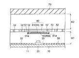
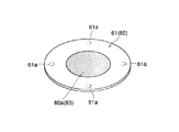
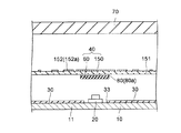
第1実施形態による光源モジュール100は、図1〜図3に示すように、筐体10、LEDパッケージ20、反射シート30および光学部材40を含んで構成されている。光学部材40は、ライティングカーテン50とこのライティングカーテン50に固定される複数の反射シート片60とを有している。また、ライティングカーテン50の上方には、光を拡散させる拡散板70が配されている。なお、LEDパッケージ20は、本発明の「光源」の一例であり、反射シート片60は、本発明の「反射層」の一例である。
The
筐体10は、光出射用の開口11を有する略箱状の部材であり、底部12とその底部12の外周に設けられた側部13とを含む。この筐体10は、たとえば、金属製の板状部材を加工することによって形成されている。そして、その底面にLEDパッケージ20および反射シート30を敷き詰めることで、これらを収容する。また、筐体10の側部13で囲まれた領域は略長方形形状(略矩形形状)となっており、その略長方形形状の領域がLEDパッケージ20および反射シート30を収容する収容領域とされている。
The
光源としてのLEDパッケージ20は、実装基板(図示せず)上に実装された状態で筐体10の内部に収容されている。実装基板は、板状かつ矩形状の基板であり、その実装面上に複数の電極が配列されている。そして、これらの電極上にLEDパッケージ20が取り付けられている。また、複数のLEDパッケージ20は同一の実装基板に実装されることでモジュール化されている。
The
LEDパッケージ20は、実装基板における実装面に形成された電極上に実装されることで電流の供給を受けて光を発する。また、図3に示すように、光源としてのLEDパッケージは、筐体10の収容領域に複数搭載されている。これら複数のLEDパッケージ20は、それぞれ、その発光面から白色の光が発せられる構造になっている。また、複数のLEDパッケージ20は、筐体10の収容領域(筐体10の底面12上)に、二次元状(たとえば、格子状)に配置されている。
The
LEDパッケージ20は、トップビュータイプである。このタイプのLEDパッケージは直上方向に強い指向性を有するものが多い。そのため、LEDパッケージ20の配光特性もこれに準ずるものとする。
The
なお、LEDパッケージ20の構造としては、特に限定されるものではないが、たとえば、青色光を黄色に変換する蛍光体と青色LED素子とを組み合わせたものとされている。あるいは、青色光を緑色および赤色にそれぞれ変換する蛍光体と青色LED素子とを組み合わせてもよいし、赤色LED素子、緑色LED素子および青色LED素子の3種類のLED素子を組み合わせてもよい。
The structure of the
反射シート30は、光を反射させる機能を有しており、たとえば、樹脂製のシート部材を加工することによって形成されている。また、反射シート30は、底部31とこの底部31の外周に設けられた側部32とを有している。反射シート30の底部31には、複数の露出穴33が設けられている。これら露出穴33は、二次元状に配置されたLEDパッケージ20と対応するように形成されている。
The
そして、図2〜図4に示すように、上記反射シート30は、LEDパッケージ20の一部が露出穴33から露出(突出)するようにして、複数のLEDパッケージ20とともに筐体10の収容領域に収容されている。これにより、筐体10の底面12および実装基板の実装面が反射シート30の底部31によって覆われ、筐体10の内側面が反射シート30の側部32によって覆われる。このように、上記反射シート30を筐体10の内部に設けることによって、反射シート30で光の反射が行われるため、被照明体側に進行する光が増大する。そのため、光の利用効率が向上する。
As shown in FIGS. 2 to 4, the
光学部材40を構成するライティングカーテン50は、筐体10の開口部分に、この開口11を塞ぐように取り付けられている。このライティングカーテン50は、LEDパッケージ20の上方に、筐体10の底部12と面するように取り付けられている。このため、LEDパッケージ20から光が発せられると、その光がライティングカーテン50に入射される。ライティングカーテン50は、LEDパッケージ20からの光を部分的に遮ることで、輝度ムラの発生を抑制する機能を有する。
The
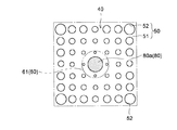
第1実施形態では、上記ライティングカーテン50は板状の反射材(反射板51)に円形状の開口52を複数設けることによって構成されている。開口52が設けられた部分は光を透過させる透過部となっており、開口52が設けられていない部分は光を反射させる反射部となっている。複数の開口52は互いに連結しないように分散配置されている。
In the first embodiment, the
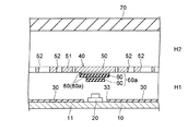
また、第1実施形態では、光源モジュール100の薄型化を図るために、ライティングカーテン50は、筐体10の底部12(底面)からの高さH1(図2参照)がたとえば約3mmの位置に取り付けられている。
In the first embodiment, in order to reduce the thickness of the
筐体10の内部に配置されたLEDパッケージ20は、その発光面の中心部が被照明体側(ライティングカーテン50側)に向けられている。LEDパッケージ20は直上方向に強い光を出射するため、ライティングカーテン50において、LEDパッケージ20の直上付近(直上部分を含む領域)に入射される光量が多く、直上付近から離れるにしたがって徐々に光量が少なくなる。このように、LEDパッケージ20から出射されてライティングカーテン50に入射される光の強度は、ライティングカーテン50の部位により異なる。そのため、ライティングカーテン50の開口52は、形成される部位によって開口率が変えられており、この開口52によって光の透過が調整されている。すなわち、複数の開口52の各大きさ(開口面積)は、均一にはなっておらず、配置位置によって異なっている。
As for the
具体的には、ライティングカーテン50は、直上付近から離れるにしたがってその開口率が徐々に高くなるように、複数の開口52の各大きさが設定されている。換言すると、ライティングカーテン50の複数の開口52の各大きさは、LEDパッケージ20の直上付近から離れるにしたがって徐々に大きくなっている。さらに、ライティングカーテン50は、LEDパッケージ20からの光の照射が強い部分(たとえば、LEDパッケージ20の直上付近)については開口52が設けられておらず、照射された光を反射する構成とされている。
Specifically, the size of each of the plurality of
なお、ライティングカーテン50に入射される光の強度の分布は、LEDパッケージ20の配光特性以外に、光源モジュールの形状、寸法、取り付け位置等(たとえば、LEDパッケージ20が並べられるピッチ、反射シート30とライティングカーテン50との間隔など)にも依存する。そのため、ライティングカーテン50のうちの光の入射量が多い部分には、光の透過量が少なくなるように開口52が形成されている。その一方、ライティングカーテン50のうちの光の入射量が少ない部分には、光の透過量が多くなるように開口52が形成されている。
In addition to the light distribution characteristics of the
また、ライティングカーテン50は、たとえば1mm程度の厚みを有する反射板51に、プレス打ち抜き加工により複数の開口52を形成することで作製される。プレス打ち抜き加工は、ランニングコストや生産性に優れるため、大量生産する場合に有効な製造方法である。開口52の加工は、プレス打ち抜き加工以外に、たとえば、ドリリング加工、レーザ加工などの手段を用いることもできる。また、ライティングカーテン50は、たとえば、反射率の高い樹脂を射出成形することによっても得ることができる。
The
ライティングカーテン50の開口52以外の部分における光反射が少ない(光吸収が多い)と、輝度ムラの発生が抑制されたとしても、輝度そのものが低くなる。そのため、ライティングカーテン50を構成する反射板51は、高い全光反射率を有する反射材から構成されているのが好ましい。これにより、輝度の低下が抑制される。このような材料としては、たとえば、微発泡PET(ポリエチレンテレフタレート)樹脂などが挙げられる。また、微発泡PET樹脂を用いた反射板として、たとえば、古河電工株式会社製の「MCPET」(登録商標)が挙げられる。古河電工株式会社製の「MCPET」(登録商標)は、厚みが1.0mmと厚く、高い全光反射率(約99%)を有している。
If the light reflection in the portion other than the
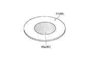
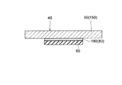
ここで、第1実施形態では、ライティングカーテン50の所定領域に、光を反射する上記反射シート片60が固定されている。この反射シート片60は、図1、図6および図7に示すように、ライティングカーテン50よりも小さい平面形状(平面積)を有している。
Here, in the first embodiment, the
反射シート片60は、反射シートを所定形状に加工した成形品である。この反射シート片60は、図2および図5に示すように、独立したシート状に形成されており、粘着層80を介して、ライティングカーテン50に固定されている。すなわち、反射シート片60は、粘着層80を構成する粘着材80aによって、ライティングカーテン50に固定されている。
The
また、反射シート片60は、ライティングカーテン50における光の入射量が多い部分に取り付けられている。そして、この反射シート片60がライティングカーテン50に取り付けられることにより、ライティングカーテン50の遮光能力が部分的に向上されている。
Further, the
図5〜図7に示すように、第1実施形態では、各反射シート片60は円形状に形成されている。そして、図1および図2に示すように、各反射シート片60は、それぞれ、LEDパッケージ20の直上付近(直上部分を含む領域)に取り付けられている。また、各反射シート片60は、ライティングカーテン50におけるLEDパッケージ20側の面上(一方の面上)に、ライティングカーテン50の開口52と重ならないように取り付けられている。具体的には、反射シート片60は、LEDパッケージ20の直上付近であって、開口52が設けられていない領域に取り付けられている。
As shown in FIGS. 5-7, in 1st Embodiment, each
反射シート片60の厚みは、たとえば、50μm〜400μmとされていると好ましく、100μm〜200μmとされているとより好ましい。ただし、反射シート片60の厚みは、反射シート片60の材質、LEDパッケージ20からの光の強度、LEDパッケージ20からライティングカーテン50までの距離等、種々の条件によって異なる。そのため、反射シート片60の厚みは、各種条件を考慮して所望の特性を有する厚みとするのが好ましい。
The thickness of the
また、反射シート片60の厚みは、ライティングカーテン50の厚みより小さく構成されていると好ましい。
Moreover, it is preferable that the thickness of the
反射シート片60を構成する反射シートは、特に制限されることはないが、たとえば、反射材を混入したPET製のシート、金属を蒸着したシート部材などを用いることができる。
The reflecting sheet constituting the reflecting
なお、反射シート片60は粘着材80aによってライティングカーテン50に固定されているため、反射シート片60とライティングカーテン50との間には粘着層80が介在された状態となっている。この場合、反射シート片60を透過した光線は粘着層80(粘着材80a)に到達し、粘着層80にて透過や反射が行われる。そのため、粘着層80(粘着材80a)の色がその後の光線の色に影響を与える場合があるので、粘着層80(粘着材80a)は白色または透明(無色透明)であるのが好ましい。粘着材80a(粘着層80)は、特に限定されることはないが、たとえば、乳白色のエマルジョン系接着剤や、透明なエポキシ系接着剤などを用いるのが好ましい。また、粘着材80a(粘着層80)は、紫外線による変色や粘着力の低下を抑制するために、耐紫外線性を有するのが好ましい。このような構成は、たとえば、紫外線吸収材が配合された粘着材を用いることで容易に実現される。粘着材80a(粘着層80)は、接着材(接着層)を含む概念である。
In addition, since the
拡散板70は、ライティングカーテン50に重なる光学シートであり、ライティングカーテン50を介して入射された光を拡散させる。拡散板70は、ライティングカーテン50の上方に、筐体10の開口11を塞ぐように取り付けられている。また、拡散板70は、ライティングカーテン50からの高さH2がたとえば約5mmの位置に取り付けられている。
The
このように構成された第1実施形態による光源モジュール100では、LEDパッケージ20から光が発せられると、ライティングカーテン50におけるLEDパッケージ20の直上付近に多くの光が入射されるが、ライティングカーテン50を透過せずに反射シート30に向かって反射される光も多くなる。一方、ライティングカーテン50におけるLEDパッケージ20の直上付近以外の部分においては、直上付近から離れるにしたがって入射する光は少なくなるが、ライティングカーテン50を透過する光(開口52を抜ける光)が直上付近から離れるにしたがって徐々に多くなる。このため、ライティングカーテン50におけるLEDパッケージ20の直上付近(直上部分および直上部分の近傍部分)から出射される光量と、ライティングカーテン50におけるLEDパッケージ20の直上付近に対して離間された部分から出射される光量との差が小さくなる。これにより、ライティングカーテン50の所定面(光出射面)から出射される面状の出射光に輝度ムラが発生し難くなる。
In the
そして、ライティングカーテン50の所定面(光出射面)から出射された面状光(輝度ムラが抑制された面状光)が、拡散板70に入射される。拡散板70に入射された面状光はさらに拡散されて、高品質な面状光として被照明体に出射される。
Then, planar light (planar light with suppressed luminance unevenness) emitted from a predetermined surface (light emitting surface) of the
上述のように、LEDパッケージ20は直上方向(垂直方向)への指向性が強いため、ライティングカーテン50におけるLEDパッケージ20の直上付近には多くの光が照射される。第1実施形態では、この領域に反射シート片60が取り付けられているため、この領域の遮光能力が向上されている。すなわち、第1実施形態では、ライティングカーテン50(光学部材40)において、多くの光が照射される領域の遮光能力が向上されている。そのため、ライティングカーテン50の遮光能力が不十分な場合でも、この領域からの光の透過が抑制されて、輝度ムラの発生が抑制される。
As described above, since the
反射シート片60が取り付けられた領域の遮光能力(全光透過率)の向上を簡単に計算する。計算を簡略化するために、粘着材80aの光学的な影響は無視する。また、光の反射は全て反射材表面で行われるものと仮定し、光の反射と透過以外は無視する。反射シート片60の全光透過率をたとえば5%、ライティングカーテン50の全光透過率をたとえば1%と仮定すると、反射シート片60とライティングカーテン50との両方を透過する光線は単純計算で0.05%となり、ライティングカーテン50のみの場合と比較して20分の1と全光透過率が極端に減少する。このように、反射シート片60を取り付けることにより、高い遮光能力が実現され、非常に多くの光が所定領域(小さい領域)に照射される場合でも輝度ムラを効果的に防ぐことが可能となる。
The improvement of the light shielding ability (total light transmittance) in the region where the
また、反射シート片60は反射シートから構成されるため、相応の反射率を有する。反射シート片60で反射された光線は反射シート30やライティングカーテン50等で何度かの反射を繰り返した後、ライティングカーテン50の開口52を介して拡散板70に到達する。したがって、LEDパッケージ20の直上付近で反射シート片60およびライティングカーテン50を透過できない光線は単純にロスすることはなく、多くの部分が最終的に照射光となる。そのため、輝度の低下は限定的となる。
Moreover, since the
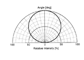
なお、光源としてLEDパッケージ20を用いた場合、CCFLを用いた場合に比べて、光源の直上付近に多くの光が集まる。この傾向は、光源モジュールの厚みが減少するにしたがい顕著となる。この点について、図8〜図11を参照して、より詳細に説明する。図8および図9は、CCFLを光源として用いた場合の配光特性を説明するための図である。図10および図11は、LEDパッケージを光源として用いた場合の配光特性を説明するための図である。なお、図9および図11の特性図は、ある角度への出射光の強度を、最大となる方向への出射の強度を100%としたときの相対強度で表している。
When the
従来に主流であった光源であるCCFLは一般に無指向性であるため、図9に示すように、その配光特性は出射角度に依存しない線光源である。無指向性の光源の場合、全角度に等しい強度で出射するため全ての角度で相対強度が100%となる。ここでは、説明を簡潔にするために光源からライティングカーテン側に照射される成分のみを考慮する。 The CCFL, which has been a mainstream light source in the past, is generally omnidirectional, and as shown in FIG. 9, its light distribution characteristic is a linear light source independent of the emission angle. In the case of an omnidirectional light source, since the light is emitted with an intensity equal to all angles, the relative intensity becomes 100% at all angles. Here, in order to simplify the explanation, only the component irradiated from the light source to the lighting curtain side is considered.
たとえば、図8に示すように、光源であるCCFL510から距離a(たとえば10mm)である照射面530において、光源(CCFL510)から図の水平方向に距離a(たとえば10mm)以内の位置に照射される(CCFL510が線光源であるため、この照射領域は帯状になる)光は、全照射のうち25%である。光源からの距離b(たとえば5mm)の照射面540では、これが35%となる。
For example, as shown in FIG. 8, the
次に、光源としてLEDパッケージを用いる場合について説明する。LEDパッケージは製品毎に特徴的な配光特性を有するが、ここではランバート分布にしたがった図11に示す配光特性を有する点光源である場合について述べる。 Next, the case where an LED package is used as the light source will be described. The LED package has a characteristic light distribution characteristic for each product. Here, a case where the LED package is a point light source having the light distribution characteristic shown in FIG. 11 according to the Lambert distribution will be described.
ランバート分布は、法線方向となす角度をθとすると角度θの方向へ照射される光の強度がcosθに比例する。このため、CCFLのような無指向性の光源と比較すると法線方向へ光が集まって照射される。すなわち、垂直方向への指向性の強い照射の分布である。 In the Lambertian distribution, when the angle formed with the normal direction is θ, the intensity of light irradiated in the direction of the angle θ is proportional to cos θ. For this reason, compared with a non-directional light source such as CCFL, light is collected and irradiated in the normal direction. That is, the distribution of irradiation with strong directivity in the vertical direction.
図10に示すように、CCFLの場合と同様、光源であるLEDパッケージ120から距離a(たとえば10mm)である照射面530において、光源(LEDパッケージ120)から図の水平方向に距離a(たとえば10mm)以内の位置に照射される(LEDパッケージ120が点光源であるため、この照射領域は円形になる)光は、全照射のうち50%である。光源からの距離b(たとえば5mm)の照射面540では、これが80%となる。
As shown in FIG. 10, as in the case of CCFL, on the
このように、LEDパッケージのような垂直方向(直上方向)への指向性が強い光源を使用する場合、光源の直上付近に多くの光が集まり、この傾向は光源モジュールの厚みが減少するにしたがい顕著になる。そのため、LEDパッケージを光源として用いた場合に、光源モジュールの薄型化を図ろうとすると、ライティングカーテンの特定部分に際だって多くの光が照射される。そのため、輝度ムラを抑制しながら、光源モジュールの薄型化を図ることが非常に困難となる。 Thus, when using a light source with strong directivity in the vertical direction (directly above), such as an LED package, a large amount of light gathers in the vicinity of the light source, and this tendency is accompanied by a decrease in the thickness of the light source module. Become prominent. Therefore, when an LED package is used as a light source, if a light source module is to be made thin, a large amount of light is irradiated to a specific portion of the lighting curtain. For this reason, it is very difficult to reduce the thickness of the light source module while suppressing luminance unevenness.
しかしながら、第1実施形態による光源モジュール100では、上記のように、反射シート片60がライティングカーテン50に取り付けられた光学部材40を備えることにより、十分な遮光能力を有するため、ライティングカーテン50の特定部分に際だって多くの光が照射される場合でも、輝度ムラが抑制される。このため、輝度ムラを抑制しながら、光源モジュール100の薄型化を図ることが可能となる。
However, in the
また、ライティングカーテン50は、反射シート片60が取り付けられた状態(光学部材40)で光源モジュール100の組立に供される。そのため、光源モジュール100の組立においては、従来と同様の工程でライティングカーテン50(光学部材40)を取り付けることができる。したがって、組立工程の工数、スループット、コスト等は従来と同等である。なお、反射シート片60の取り付けは、たとえば、複数一括貼り付けなどを行うことにより、容易に取り付けることが可能である。
The
第1実施形態では、上記のように、ライティングカーテン50に反射シート片60を取り付けることによって、ライティングカーテン50の一部の領域に光源(LEDパッケージ20)から多量の光が照射された場合に、その光を反射シート片60とライティングカーテン50との両方で遮光することができる。このため、十分な遮光能力を得ることができるので、ライティングカーテン50の特定部分に際だって多くの光が照射される場合でも、その光を十分に遮光することができる。そのため、LEDパッケージ20のような指向性の強い光源を利用した場合あるいはモジュールを薄型化した場合でも、ライティングカーテン50を通して出射される光(照明光)に輝度ムラを生じ難くすることができる。
In the first embodiment, as described above, by attaching the
また、第1実施形態では、反射シート片60をライティングカーテン50よりも小さい平面形状(平面積)とすることによって、光源(LEDパッケージ20)から多量の光が照射される一部の領域のみに反射シート片60を設けることができる。これにより、ライティングカーテン50の遮光能力を向上させるために、ライティングカーテンの厚みを大きくしたり、複数のライティングカーテンを積層したりする場合に比べて、素材コストの増加および重量の増加等を抑制することができる。また、ライティングカーテン50に反射シート片60を設けた場合には、ライティングカーテン自体の厚みは増加しないため、ライティングカーテン50の厚みが増加することに起因して、光源モジュール100の厚みが増加するという不都合が生じるのを抑制することもできる。
In the first embodiment, the
このように、第1実施形態では、指向性の強い光源を利用した場合でも、光源モジュール100の薄型化を図ることができる。また、そのように構成した場合でも、輝度ムラの抑制された均一な照明光を発することができる。
Thus, in the first embodiment, the
さらに、第1実施形態では、上記のように構成することによって、複数のライティングカーテンを用いることなく遮光能力を向上させることができる。このため、複数のライティングカーテンを用いた場合に生じる不都合を回避することができる。たとえば、光源モジュール100の組立時に複数のライティングカーテンを取り付けかつ各ライティングカーテンの位置合わせを考慮する必要がなくなる。そのため、ライティングカーテンの取り付け精度の向上、取り付け工程のコスト削減、取り付け工程のスループット向上等を実現することが可能となる。
Furthermore, in 1st Embodiment, the light shielding capability can be improved without using a some lighting curtain by comprising as mentioned above. For this reason, the inconvenience which arises when using several lighting curtains can be avoided. For example, when assembling the
また、第1実施形態では、ライティングカーテン50に、開口52によって透過部が設けられた反射板51からなるライティングカーテンを用いているため、このようなライティングカーテン50に反射シート片60を設けることによって、容易に、被照明体に対する照明をムラなく均一に行うことが可能な光源モジュール100を得ることができる。
In the first embodiment, the
上記した光源モジュール100は、図3に示すように、たとえば、液晶表示装置300のバックライトユニット100(直下型バックライトユニット)として用いることができる。
As shown in FIG. 3, the above-described
この液晶表示装置300は、液晶表示パネル200(被照明体)と、この液晶表示パネル200に対して光を供給する上記バックライトユニット100(光源モジュール100)とを備える。液晶表示パネル200は、たとえば、TFT(Thin Film Transistor)などのスイッチング素子を含むアクティブマトリックス基板201と、このアクティブマトリックス基板201に対向する対向基板202とをシール材(図示せず)で貼り合わせることによって構成されている。また、両基板201および202の隙間には、液晶(図示せず)が注入されている。そして、アクティブマトリックス基板201の受光面側および対向基板202の出射面側には、それぞれ、偏光フィルム203が取り付けられている。
The liquid
このように構成された液晶表示パネル200は、液晶分子の傾きに起因する透過率の変化を利用して、画像を表示する。また、液晶表示パネル200を照明するバックライトユニット100に上記光源モジュール100が用いられているため、表示機能の優れた薄型の液晶表示装置300を実現することができる。
The liquid
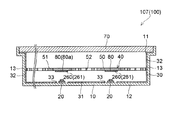
(第2実施形態)
図12は、本発明の第2実施形態による光源モジュールの断面図であり、図13は、図12の一部を拡大して示した断面図である。図14は、本発明の第2実施形態による光源モジュールにおける反射シート片の斜視図であり、図15は、本発明の第2実施形態による光源モジュールにおけるライティングカーテンの一部を示した平面図である。次に、図12〜図15を参照して、本発明の第2実施形態による光源モジュールについて説明する。なお、各図において、対応する構成要素には同一の符号を付すことにより、重複する説明は適宜省略する。
(Second Embodiment)
FIG. 12 is a cross-sectional view of a light source module according to a second embodiment of the present invention, and FIG. 13 is a cross-sectional view illustrating a part of FIG. FIG. 14 is a perspective view of a reflective sheet piece in the light source module according to the second embodiment of the present invention, and FIG. 15 is a plan view showing a part of the lighting curtain in the light source module according to the second embodiment of the present invention. is there. Next, with reference to FIGS. 12-15, the light source module by 2nd Embodiment of this invention is demonstrated. In addition, in each figure, the same code | symbol is attached | subjected to a corresponding component, and the overlapping description is abbreviate | omitted suitably.
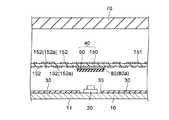
この第2実施形態による光源モジュール101(100)では、図12および図13に示すように、反射シート片61(60)がライティングカーテン50の開口52の少なくとも一部を覆うように構成されている。すなわち、第2実施形態では、反射シート片61が、ライティングカーテン50の開口52の少なくとも一部と重なるように、ライティングカーテン50に取り付けられている。
In the light source module 101 (100) according to the second embodiment, the reflection sheet piece 61 (60) is configured to cover at least a part of the
ライティングカーテン50に設けられた複数の開口52のうち反射シート片61に覆われた部分(反射シート片61と重なる部分)は、反射シート片61のみで遮光される。このため、この部分は、開口52部分と比べると全光透過率が低くなり、かつ、反射シート片61とライティングカーテン50との両方で遮光される部分(領域)に比べると全光透過率が高くなる。そのため、反射シート片61で開口52が覆われた部分は中間的な全光透過率となる。
Of the plurality of
なお、反射シート片61の全面に粘着材80a(図14参照)を塗布した場合、粘着材80a(粘着層80)によってライティングカーテン50の開口52が塞がれるおそれがある。そのため、第2実施形態においては、粘着材80a(粘着層80)は、ライティングカーテン50の開口52を避けた領域に塗布(形成)するのが好ましい。この場合、シルク印刷などの印刷法を用いて粘着材80aを塗布すれば、所定領域に精度よく、かつ、容易に粘着材80a(粘着層80)を塗布(形成)することが可能となる。
In addition, when the
また、印刷法を用いて粘着材80aを塗布する場合、図14に示すように、反射シート片61に粘着材80a(粘着層80)を塗布(形成)してもよいし、図15に示すように、ライティングカーテン50の所定領域に粘着材80a(粘着層80)を塗布(形成)してもよい。また、反射シート片61およびライティングカーテン50の両方に粘着材80a(粘着層80)を塗布(形成)してもよい。
Moreover, when apply | coating the
第2実施形態のその他の構成は、上記第1実施形態と同様である。 Other configurations of the second embodiment are the same as those of the first embodiment.
第2実施形態では、上記のように、ライティングカーテン50の開口52の少なくとも一部が反射シート片61と重なるように構成することによって、たとえば、ライティングカーテン50では透過されるが反射シート片61では反射される中間的な遮光能力を持つ領域を形成することができる。これにより、光源モジュールの設計自由度を向上させることができる。また、ライティングカーテン50における透過率のパターン(開口パターン)の設計自由度を向上させることもできる。
In the second embodiment, as described above, by configuring at least a part of the
また、本来であればライティングカーテン50に微細な開口52が要求される部分に、上記構成を利用することで、開口サイズを大きくすることができる。開口サイズを大きくした場合に、その開口52を反射シート片61で覆うことで、本来の開口サイズの遮光能力と同等の遮光能力とすることができる。これにより、ライティングカーテン50の製造工程において、開口52の形成を容易に低コストで実現することができる。
In addition, the opening size can be increased by using the above-described configuration in a portion where a
たとえば、開口52の一部の寸法が小さすぎてライティングカーテン50を射出成形で製造することが困難な場合でも、開口52の寸法を大きくすれば製造が可能となる場合もある。あるいは、プレス打ち抜き加工によって開口52を形成する場合においても、開口52の寸法が小さければ加工が困難となるおそれがあるものの、開口52の寸法を大きくすれば製造が可能となる場合もある。さらに、寸法が大きければ一般に寸法公差を大きくすることができるため、品質や歩留まりの向上にも貢献する。
For example, even if it is difficult to manufacture the
あるいは、たとえば、設計の不適合などにより、ライティングカーテン50の開口52が適正なものより大きくなっている場合や余計な開口52が設けられた場合に、修復目的で、開口52を反射シート片61で覆うこともできる。また、ライティングカーテン50に反射シート片61の位置合わせを目的とした開口を設け、反射シート片61の取り付け時に位置を合わせる、あるいは位置が合っていることを確認する目的で上記構成を用いることもできる。
Alternatively, for example, when the
第2実施形態のその他の効果は、上記第1実施形態と同様である。 Other effects of the second embodiment are the same as those of the first embodiment.
(第3実施形態)
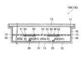
図16は、本発明の第3実施形態による光源モジュールの断面図であり、図17は、図16の一部を拡大して示した断面図である。図18は、本発明の第3実施形態による光源モジュールにおける反射シート片の斜視図であり、図19は、本発明の第3実施形態による光源モジュールにおけるライティングカーテンの一部を示した平面図である。次に、図16〜図19を参照して、本発明の第3実施形態による光源モジュールについて説明する。なお、各図において、対応する構成要素には同一の符号を付すことにより、重複する説明は適宜省略する。
(Third embodiment)
FIG. 16 is a cross-sectional view of a light source module according to a third embodiment of the present invention, and FIG. 17 is an enlarged cross-sectional view of a part of FIG. FIG. 18 is a perspective view of a reflective sheet piece in a light source module according to the third embodiment of the present invention, and FIG. 19 is a plan view showing a part of a lighting curtain in the light source module according to the third embodiment of the present invention. is there. Next, with reference to FIGS. 16-19, the light source module by 3rd Embodiment of this invention is demonstrated. In addition, in each figure, the same code | symbol is attached | subjected to a corresponding component, and the overlapping description is abbreviate | omitted suitably.
この第3実施形態による光源モジュール102(100)では、図16および図17に示すように、反射シート片61(60)の一部にライティングカーテン50と共通の開口孔61aが設けられている。すなわち、第3実施形態では、反射シート片61に、ライティングカーテン50の開口52と重なる開口孔61aが設けられている。これにより、反射シート片61が設けられた高い遮光能力を持つ部分(反射部)を開口52と隣接させることができる。その結果、開口52の周囲にわたって遮光能力を高めることができる。
In the light source module 102 (100) according to the third embodiment, as shown in FIGS. 16 and 17, an
ライティングカーテン50と反射シート片61とに同じ形状の開口を設けることは、たとえば、ライティングカーテン50に反射シート片61を貼り付けた後にプレス打ち抜き加工などを施すことにより、容易に、かつ高精度に実現できる。また、この加工をさらに容易にするため、開口される部分やその周辺部分は、図17に示すように、粘着材80a(粘着層80)が存在しないことが好ましい。これらの部分に粘着材80a(粘着層80)が存在すれば、プレス打ち抜き加工時の金型に粘着材が付着するという不都合が生じる。あるいは粘着材が開口の周囲に不定形に付着するという不都合が生じる。その一方、上記のように構成することにより、これらの不都合を解消することができる。
The opening of the same shape in the
また、開口される部分やその周辺部分を避けた領域(開口孔61aを避けた領域)に粘着層80(粘着材80a)を設ける場合、シルク印刷などの印刷法を用いて粘着材80aを塗布すれば、所定領域に精度よく、かつ、容易に粘着材80a(粘着層80)を塗布(形成)することが可能となる。
Further, when the adhesive layer 80 (
また、印刷法を用いて粘着材80aを塗布する場合、図18に示すように、反射シート片61に粘着材80a(粘着層80)を塗布(形成)してもよいし、図19に示すように、ライティングカーテン50の所定領域に粘着材80a(粘着層80)を塗布(形成)してもよい。また、反射シート片61およびライティングカーテン50の両方に粘着材80a(粘着層80)を塗布(形成)してもよい。
Moreover, when apply | coating the
なお、反射シート片61はライティングカーテン50の一部の領域に貼り付けられているため、ライティングカーテン50全体の厚みを大きくなることはない。すなわち、反射シート片61が設けられることで厚みが大きくなる領域は限定的である。そのため、プレス打ち抜き加工により、ライティングカーテン50と反射シート片61とに開口を設ける場合でも、厚みの大きいライティングカーテンに開口を設ける場合などと比べて、プレスに加える応力(荷重)が小さくてすむので、開口の加工が容易となる。
In addition, since the
第3実施形態のその他の構成および効果は、上記第1および第2実施形態と同様である。 Other configurations and effects of the third embodiment are the same as those of the first and second embodiments.
(第4実施形態)
図20は、本発明の第4実施形態による光源モジュールの断面図である。図21は、図20の一部を拡大して示した断面図である。図22は、本発明の第4実施形態による光源モジュールにおけるライティングカーテンの一部を示した平面図である。次に、図20〜図22を参照して、本発明の第4実施形態による光源モジュールについて説明する。なお、各図において、対応する構成要素には同一の符号を付すことにより、重複する説明は適宜省略する。
(Fourth embodiment)
FIG. 20 is a cross-sectional view of a light source module according to a fourth embodiment of the present invention. FIG. 21 is an enlarged cross-sectional view of a part of FIG. FIG. 22 is a plan view showing a part of the lighting curtain in the light source module according to the fourth embodiment of the present invention. Next, with reference to FIGS. 20-22, the light source module by 4th Embodiment of this invention is demonstrated. In addition, in each figure, the same code | symbol is attached | subjected to a corresponding component, and the overlapping description is abbreviate | omitted suitably.
第4実施形態による光源モジュール103(100)は、上記第1〜第3実施形態とはライティングカーテンの構成が異なる。すなわち、第4実施形態では、図20および図21に示すように、透明板151に反射材152が塗布されることによって形成されたライティングカーテン150を備えている。より具体的には、ライティングカーテン150は、たとえば、ポリカーボネート製の透明板151に、白色インクや金属インクなどの全光透過率の低いインク(反射材152)を塗布することで形成されている。なお、透明板151は、本発明の「板状部材」の一例である。
The light source module 103 (100) according to the fourth embodiment is different from the first to third embodiments in the configuration of the lighting curtain. That is, in the fourth embodiment, as shown in FIGS. 20 and 21, a
反射材152の塗布には、印刷法を用いることができる。このように、反射材152を印刷する方法は、単価や初期費用が安価で生産性が高いという長所を有する。また、印刷法を用いることで、微細なパターンや他の成形方法では実現が難しい形状(たとえば、多数のドットの集合など)を容易に実現できるため、設計自由度が高いという長所も有する。
A printing method can be used to apply the
反射材152の印刷は、シルク印刷が好ましい。ただし、シルク印刷以外に、たとえば、インクジェット法やオフセット印刷などであってもよい。
The printing of the
また、ライティングカーテン150のうちの光の入射量が多い部分には、光の透過量が少なくなるように反射材152が印刷されている。その一方、ライティングカーテン150のうちの光の入射量が少ない部分には、光の透過量が多くなるような反射材152が印刷されている。たとえば、透明板151に、図22に示すようなパターンで反射材152が印刷されている。図22において、反射材152が印刷された部分は、光を反射する反射部A(遮光部)とされており、反射材152が印刷されていない部分は、光を透過する透過部Bとされている。すなわち、透明板151は光を透過するが、反射材152に照射された光は大部分が反射される。そのため、反射材152の印刷によって、透過部Bと反射部A(遮光部)とが形成されている。これにより、第4実施形態によるライティングカーテン150も上記第1〜第3実施形態で示したライティングカーテンと同様の機能を備える。
A
また、図21に示すように、高い遮光能力が要求される領域(光源から多量の光が照射される領域)には、透明板151に反射材152が塗布され、かつ、反射シート片60が貼り付けられている。
In addition, as shown in FIG. 21, in a region where a high light shielding capability is required (a region where a large amount of light is irradiated from a light source), a
上記第1実施形態と同様に、反射シート片60が取り付けられた領域の遮光能力(全光透過率)の向上を簡単に計算する。計算を簡略化するために、粘着材80aの光学的な影響は無視する。また、光の反射は全て反射材表面で行われると仮定し、光の反射と透過以外は無視する。反射シート片60の全光透過率をたとえば5%、反射材152の全光透過率をたとえば10%と仮定すると、反射シート片60と反射材152との両方を透過する光線は単純計算で0.5%となり、反射材152のみ、あるいは反射シート片60のみの場合と比較して遮光能力が高い。
Similar to the first embodiment, the improvement of the light shielding ability (total light transmittance) in the region where the
一般に、印刷によってライティングカーテンを形成する手法は安価であるものの、全光透過率が高くなりがちである。しかしながら、遮光能力が不十分な部分に反射シート片60を設けることで、その部分の遮光能力を反射シート片60で補うことができる。これにより、印刷法によって作製されたライティングカーテン150を用いた場合でも、十分な遮光能力が得られる。
In general, although the method of forming a lighting curtain by printing is inexpensive, the total light transmittance tends to be high. However, by providing the
なお、第4実施形態では、一例として、透明板151の上面(反射シート片60が設けられている面と反対側の面)に反射材152を印刷した例を示している。また、反射材152の印刷によって、透明板151には反射材152からなる印刷層152aが形成されている。
In addition, in 4th Embodiment, the example which printed the reflecting
(第5実施形態)
図23は、本発明の第5実施形態による光源モジュールの断面図である。図24は、図20の一部を拡大して示した断面図である。図25は、本発明の第5実施形態による光源モジュールにおけるライティングカーテンの一部を拡大して示した断面図である。次に、図23〜図25を参照して、本発明の第5実施形態による光源モジュールについて説明する。なお、各図において、対応する構成要素には同一の符号を付すことにより、重複する説明は適宜省略する。
(Fifth embodiment)
FIG. 23 is a cross-sectional view of a light source module according to a fifth embodiment of the present invention. 24 is an enlarged cross-sectional view of a part of FIG. FIG. 25 is an enlarged sectional view showing a part of a lighting curtain in a light source module according to a fifth embodiment of the present invention. Next, with reference to FIGS. 23-25, the light source module by 5th Embodiment of this invention is demonstrated. In addition, in each figure, the same code | symbol is attached | subjected to a corresponding component, and the overlapping description is abbreviate | omitted suitably.
この第5実施形態による光源モジュール104(100)では、図23〜図25に示すように、ライティングカーテン150を構成する透明板151の両面に反射材152が塗布(印刷)されている。このため、透明板151の上面上および下面上のそれぞれに、反射材152の印刷による印刷層152aが形成されている。
In the light source module 104 (100) according to the fifth embodiment, as shown in FIGS. 23 to 25, the reflecting
ここで、ある程度以上の強度の光がライティングカーテン150によっても反射シート片60によっても反射されずに光出射面から直接的に出射されると輝度ムラの原因となる場合がある。そのため、ある程度以上の強度の光については、透明板151のいずれかの面に印刷された反射材152(印刷層152a)または反射シート片60により反射された後に出射されるように、反射材152(印刷層152a)の印刷パターンや反射シート片60の形状および位置が設定されているのが好ましい。
Here, when light of a certain intensity or more is directly reflected from the light exit surface without being reflected by the
具体的には、反射材152の各印刷パターンは、少なくともLEDパッケージ20の直上(直上付近)からの距離が比較的小さい領域(照射される光の強度がある程度大きな領域)においては、LEDパッケージ20からの光が少なくとも一方の面に印刷(塗布)された反射材152(印刷層152a)に照射されるように構成されているのが好ましい。すなわち、LEDパッケージ20からの光が反射材152(印刷層152a)に照射されることなくライティングカーテン150を透過することがないように、反射材152(印刷層152a)が形成されているのが好ましい。
Specifically, each printed pattern of the reflecting
たとえば、図25に示すように、各印刷パターンは、透明板151の一方の面(たとえば上面)における反射材152(印刷層152a)が形成されていない部分(領域)を、他方の面(たとえば下面)における反射材152(印刷層152a)で覆うように形成される。
For example, as shown in FIG. 25, each print pattern has a portion (area) where the reflective material 152 (
このように構成されていれば、光源(LEDパッケージ20)から発生する光は必ず反射材152あるいは周辺の反射シート30等の何らかに照射される。そして、反射や透過を経て初めて光出射面へと至る。これにより、強い光が直接的に出射されることに起因する輝度ムラが抑制される。また、直上付近の領域(遮光能力を高める必要がある領域)に反射シート片60を備えることで、その領域の遮光能力を十分に高めることができる。
If configured in this way, the light generated from the light source (LED package 20) is always applied to the reflecting
第5実施形態のその他の構成は、上記第4実施形態と同様である。また、第5実施形態のその他の効果は、上記第1〜第4実施形態と同様である。 Other configurations of the fifth embodiment are the same as those of the fourth embodiment. The remaining effects of the fifth embodiment are similar to those of the aforementioned first to fourth embodiments.
(第6実施形態)
図26は、本発明の第6実施形態による光源モジュールの断面図であり、図27は、図26の一部を拡大して示した断面図である。図28は、本発明の第6実施形態による光源モジュールにおける反射シート片を示した斜視図であり、図29は、本発明の第6実施形態による反射シート片の取り付け状態を示した断面図である。次に、図26〜図28を参照して、本発明の第6実施形態による光源モジュールについて説明する。なお、各図において、対応する構成要素には同一の符号を付すことにより、重複する説明は適宜省略する。
(Sixth embodiment)
FIG. 26 is a cross-sectional view of a light source module according to a sixth embodiment of the present invention, and FIG. 27 is an enlarged cross-sectional view of a part of FIG. FIG. 28 is a perspective view showing a reflective sheet piece in a light source module according to a sixth embodiment of the present invention, and FIG. 29 is a cross-sectional view showing an attached state of the reflective sheet piece according to the sixth embodiment of the present invention. is there. Next, with reference to FIGS. 26-28, the light source module by 6th Embodiment of this invention is demonstrated. In addition, in each figure, the same code | symbol is attached | subjected to a corresponding component, and the overlapping description is abbreviate | omitted suitably.
この第6実施形態による光源モジュール105(100)では、反射シート片の構成が上記第1実施形態と異なる。具体的には、第6実施形態では、図26〜図29に示すように、反射シート片160(60)が、基材161上に反射材162が印刷(塗布)されることによって形成されている。すなわち、第6実施形態の反射シート片160は、基材161上に反射材162が形成された反射部材(第1反射部材)からなる。
In the light source module 105 (100) according to the sixth embodiment, the configuration of the reflective sheet piece is different from that of the first embodiment. Specifically, in the sixth embodiment, as shown in FIGS. 26 to 29, the reflective sheet piece 160 (60) is formed by printing (applying) the
第1実施形態で示した反射シート片は、反射シートを特定の形状に加工することによって形成されるため、要求される形状が複雑であったり微細であったりする場合、反射シートを複雑・微細に加工する必要がある。これに対し、第6実施形態では、基材161に反射材162を印刷することで反射シート片160が形成されるため、遮光性を高める必要のある領域(形状)を印刷にて形成することができる。このため、形状の自由度が非常に高いため、複雑な形状や微細な形状であっても容易に形成することが可能となる。
Since the reflective sheet piece shown in the first embodiment is formed by processing the reflective sheet into a specific shape, if the required shape is complicated or fine, the reflective sheet is complicated and fine. Need to be processed. On the other hand, in the sixth embodiment, since the
第6実施形態のその他の構成は、上記第1実施形態と同様である。 Other configurations of the sixth embodiment are the same as those of the first embodiment.
第6実施形態では、上記のように、反射シート片160を、基材161に反射材162が印刷された反射部材から構成することによって、光を反射させる領域(反射材162が印刷された反射領域)を複雑なパターンや微細なパターンに形成することができる。このため、遮光性を高める必要のある領域に精度よく反射材162を塗布することができるので、その領域の遮光性を容易に高めることができる。
In the sixth embodiment, as described above, the
なお、反射シート片160を構成する基材161には、たとえば、透明のポリカーボネート板などを用いることができる。基材161にポリカーボネート板を用いることにより、透明部に十分な透過性を持たせることができる。また、反射材162には、たとえば、白色インクや金属インクなどを用いることができる。
For example, a transparent polycarbonate plate can be used as the
また、上記基材161を反射シートから構成することもできる。すなわち、上記反射シート片160を、反射シート(基材161)にさらに反射材162が印刷された反射部材(第2反射部材)から構成することもできる。このように構成すれば、反射シート片160が、反射シートとその上に印刷された反射材162とによって構成されるので、反射シート片160が複数の層から構成されることになる。このため、反射シート片160の反射能力をさらに高めることができるので、反射シート片160が設けられたライティングカーテン50の遮光能力もさらに高めることができる。
Moreover, the said
第6実施形態のその他の効果は、上記第1実施形態と同様である。 The other effects of the sixth embodiment are the same as those of the first embodiment.
(第7実施形態)
図30は、本発明の第7実施形態による光源モジュールの断面図である。図31は、図30の一部を拡大して示した断面図である。次に、図30および図31を参照して、本発明の第7実施形態による光源モジュールについて説明する。なお、各図において、対応する構成要素には同一の符号を付すことにより、重複する説明は適宜省略する。
(Seventh embodiment)
FIG. 30 is a cross-sectional view of a light source module according to a seventh embodiment of the present invention. FIG. 31 is an enlarged cross-sectional view of a part of FIG. Next, with reference to FIG. 30 and FIG. 31, the light source module by 7th Embodiment of this invention is demonstrated. In addition, in each figure, the same code | symbol is attached | subjected to a corresponding component, and the overlapping description is abbreviate | omitted suitably.
この第7実施形態による光源モジュール106(100)では、図30および図31に示すように、ライティングカーテン50に反射シート片60が粘着材80aにて取り付けられており、反射シート片60にさらに別の反射シート片60が粘着材80aにて取り付けられている。すなわち、第7実施形態では、複数の反射シート片が重ねて取り付けられている。このため、第7実施形態の反射シート片60aは、ライティングカーテン50に直接取り付けられる第1の反射シート片60(第1反射層)と、この反射シート片60に取り付けられる第2の反射シート片60(第2反射層)とを含んだ構成となっている。
In the light source module 106 (100) according to the seventh embodiment, as shown in FIGS. 30 and 31, a
第7実施形態のその他の構成は、上記第1実施形態と同様である。 Other configurations of the seventh embodiment are the same as those of the first embodiment.
第7実施形態では、反射シート片60aを上記のように構成することによって、極めて高い遮光能力が要求される場合、あるいは反射シート片60を遮光能力が比較的低い素材から構成する場合でも対応することができる。
In the seventh embodiment, the
第7実施形態のその他の効果は、上記第1実施形態と同様である。 The other effects of the seventh embodiment are the same as those of the first embodiment.
(第8実施形態)
図32は、本発明の第8実施形態による光源モジュールの光学部材の一部を示した断面図である。図33は、本発明の第8実施形態による光源モジュールの光学部材の一部(他の例)を示した断面図である。次に、図32および図33を参照して、本発明の第8実施形態による光源モジュールについて説明する。なお、各図において、対応する構成要素には同一の符号を付すことにより、重複する説明は適宜省略する。
(Eighth embodiment)
FIG. 32 is a cross-sectional view showing a part of an optical member of a light source module according to an eighth embodiment of the present invention. FIG. 33 is a sectional view showing a part (another example) of the optical member of the light source module according to the eighth embodiment of the present invention. Next, with reference to FIG. 32 and FIG. 33, the light source module by 8th Embodiment of this invention is demonstrated. In addition, in each figure, the same code | symbol is attached | subjected to a corresponding component, and the overlapping description is abbreviate | omitted suitably.
この第8実施形態では、上記第1〜第7実施形態とは異なり、反射シート片60が両面テープ180でライティングカーテン50(150)に取り付けられている。両面テープ180は、図32に示すように、基材181と、その両面に塗布された粘着層80(粘着材)とから構成されている。
In the eighth embodiment, unlike the first to seventh embodiments, the
このように、反射シート片60の取り付けに両面テープ180を用いることも可能である。しかしながら、両面テープ180を用いた場合、反射シート片60を透過した光は粘着層80(粘着材)に照射されるが、そこを透過した光はさらに基材181に照射される。そして、この光がさらに透過・反射を繰り返した後に外部に出射される。このため、両面テープ180を用いた場合には、その粘着層80(粘着材)のみならず、基材181も光学的に光源モジュールからの照射に影響を与えるおそれがある。したがって、反射シート片60の取り付けに両面テープ180を用いる場合、その粘着層80(粘着材)だけではなく、基材181についても白色または透明(無色透明)であるのが好ましい。このような両面テープの一例として、PETやPMMAを基材181とした両面テープが挙げられる。
Thus, it is possible to use the double-
また、図33に示すように、反射シート片60の取り付けに、基材レスの両面テープ180を用いることもできる。このような基材レスの両面テープ180を用いることにより、基材の影響を考慮する必要がなくなるのでより好ましい。なお、この場合、上記第1実施形態で示したように、粘着材にて反射シート片60を取り付ける場合と同様となる。
Further, as shown in FIG. 33, a baseless double-
また、両面テープを用いる場合であっても、その粘着層(粘着材)は光源からの光の影響を受ける。そのため、両面テープにおいても、その粘着層(粘着材)は耐紫外線性を有しているのが好ましい。これは、紫外線吸収剤が配合された粘着材を用いることで容易に実現できる。 Even when a double-sided tape is used, the adhesive layer (adhesive material) is affected by light from the light source. Therefore, also in the double-sided tape, the adhesive layer (adhesive material) preferably has UV resistance. This can be easily realized by using an adhesive material containing a UV absorber.
(第9実施形態)
図34は、本発明の第9実施形態による光源モジュールの断面図である。図35は、図34の一部を拡大して示した断面図である。次に、図34および図35を参照して、本発明の第9実施形態による光源モジュールについて説明する。なお、各図において、対応する構成要素には同一の符号を付すことにより、重複する説明は適宜省略する。
(Ninth embodiment)
FIG. 34 is a cross-sectional view of the light source module according to the ninth embodiment of the present invention. FIG. 35 is an enlarged cross-sectional view of a part of FIG. Next, with reference to FIG. 34 and FIG. 35, the light source module by 9th Embodiment of this invention is demonstrated. In addition, in each figure, the same code | symbol is attached | subjected to a corresponding component, and the overlapping description is abbreviate | omitted suitably.
この第9実施形態による光源モジュール107(100)では、図34および図35に示すように、反射シート片に代えて、反射層260がライティングカーテン50の所定領域に形成されている。この反射層260は、反射材261がライティングカーテン50に印刷されることで形成されている。すなわち、この第9実施形態は、反射層260がライティングカーテン50に印刷にて形成および固定されている点で、別体で形成された反射シート片が粘着材で固定された上記第1実施形態と異なる。
In the light source module 107 (100) according to the ninth embodiment, as shown in FIGS. 34 and 35, a
反射層260の形成は、シルク印刷、オフセット印刷、インクジェット法などの種々の印刷法を用いて行うことができるが、なかでも、シルク印刷が好ましい。また、反射層260の形成(反射材261の印刷)は、ライティングカーテン50に開口52を設ける加工を実施する前であってもよいし、加工を実施した後であってもよい。
The
反射材261としては、たとえば、白色インクや金属インクを用いることができる。金属インクは、白色インクと比較すると反射率が劣ることが多いため輝度のロスが増すものの、薄い厚みで高い遮光能力を実現することができる。また、印刷に白色インクを用いることにより、その後の光線の色の変化を抑制して遮光能力を高めることができる。
As the
また、反射材261が塗布された領域(反射層260が形成された領域)は、塗布されない領域(反射層260が形成されていない領域)と比較すると、反射材261(反射層260)によってより光を反射する構成となる。そのため、その領域の遮光能力が向上する。すなわち、上記構成によって、簡易な手段にて局所的にライティングカーテン50の遮光能力を高めることができる。反射層260の厚みは、どの程度、遮光能力を向上させる必要があるかにもよるが、たとえば、20μm〜100μmとすることができる。
In addition, the region where the
さらに、第9実施形態では、ライティングカーテン50に対して印刷を行うことで反射層260の形成(遮光能力の向上)が実現できるため、上記第1実施形態に比べて、さらにコストを低減できる可能性がある。
Further, in the ninth embodiment, since the
なお、図34および図35では、ライティングカーテン50のLEDパッケージ20側の面に反射層260を形成した例を示しているが、LEDパッケージ20と反対側の面に反射層260を形成してもよい。すなわち、反射層260の形成(反射材261の印刷)は、ライティングカーテン50のいずれか一方の面に行うことができる。また、ライティングカーテン50の両面に反射層260を形成してもよい。
34 and 35 show an example in which the
片面のみに反射層260を形成した場合に遮光能力が不足する場合、ライティングカーテン50の両面に反射層260を形成するのが好ましい。この場合、両面に必ずしも同一のパターンを印刷する必要はなく、異なるパターンを印刷することも可能である。このように、異なるパターンを印刷した場合、両面の反射層260(反射材261)にて反射させる領域と旗面の反射層260(反射材261)のみで反射させる領域とを設けることにより、中間的な反射率を有する領域を形成することができる。そのため、印刷パターンの設計自由度を高めることができる。
When the
第9実施形態のその他の構成および効果は、上記第1実施形態と同様である。 Other configurations and effects of the ninth embodiment are the same as those of the first embodiment.
(第10実施形態)
図36は、本発明の第10実施形態による光源モジュールの断面図である。図37は、図36の一部を拡大して示した断面図である。次に、図36および図37を参照して、本発明の第10実施形態による光源モジュールについて説明する。なお、各図において、対応する構成要素には同一の符号を付すことにより、重複する説明は適宜省略する。
(10th Embodiment)
FIG. 36 is a cross-sectional view of the light source module according to the tenth embodiment of the present invention. FIG. 37 is an enlarged sectional view of a part of FIG. Next, with reference to FIG. 36 and FIG. 37, the light source module by 10th Embodiment of this invention is demonstrated. In addition, in each figure, the same code | symbol is attached | subjected to a corresponding component, and the overlapping description is abbreviate | omitted suitably.
この第10実施形態による光源モジュール108(100)では、上記第9実施形態の構成において、反射層260の一部にライティングカーテン50の開口52と共通の開口孔260aが設けられている。すなわち、第10実施形態では、図36および図37に示すように、反射層260に、ライティングカーテン50の開口52と重なる開口孔260aが設けられている。
In the light source module 108 (100) according to the tenth embodiment, an
この構成により、開口52の周囲にわたって反射材261が塗布されていない場合と比較して、反射部(反射層260が形成された部分)の遮光能力を高めることができる。
With this configuration, the light shielding ability of the reflective portion (the portion where the
また、上記構成は、ライティングカーテン50に反射材261を印刷(反射層260を形成)した後、開口52を形成する加工を行うことで容易に実現することができる。
In addition, the above configuration can be easily realized by printing the
(第11実施形態)
図38〜図41は、本発明の第11実施形態による光学部材の一部を示した平面図である。次に、図38〜図41を参照して、この第11実施形態では反射シート片(反射層)の形状についてより具体的に説明する。
(Eleventh embodiment)
38 to 41 are plan views showing part of the optical member according to the eleventh embodiment of the present invention. Next, with reference to FIGS. 38 to 41, in the eleventh embodiment, the shape of the reflective sheet piece (reflective layer) will be described more specifically.
図38に示すように、光学部材40を構成する反射シート片60は、たとえば、円形とすることができる。反射シート片60は反射シートから構成されているためその全面が反射部となっている。このような反射シート片60は、たとえば、反射シートの片面の全面に粘着材を塗布した後、円形に切り抜き加工することで得られる。切り抜き加工された後の状態はシール状の形態となっているため、ライティングカーテン50に容易に貼り付けることが可能となる。
As shown in FIG. 38, the
印刷により反射層260とする場合は、反射材を円形に印刷することにより、上記形状が容易に実現できる。
When the
他の例として、図39に示すように、光学部材40を構成する反射シート片60を、たとえば、複数のリング状の反射部120を有する円形とすることができる。このような反射シート片60は、たとえば、透明板に反射材を同心円の反射部120のパターンに印刷し、透明板の反対面に粘着材を塗布することで実現できる。
As another example, as shown in FIG. 39, the reflecting
このような形状の反射層(反射シート片)を、反射シートの切り抜き加工で作製する場合、複数の反射シート片が必要となる。また、ライティングカーテンへの貼り付け加工も複数に分けて実施され、かつ各反射シート片の間で位置合わせが必要となる。このため、上記のように、印刷により反射部120を形成することで、図39に示したような複数の反射部120にて反射部のパターンが形成される場合も、容易に、かつ、低コストで実現できる。したがって、形状によっては加工が困難な微細または複雑な反射層の形状であっても実現できる。また、印刷により反射層260とする場合も、同様に、上記形状を容易に実現できる。
When the reflective layer (reflective sheet piece) having such a shape is produced by cutting the reflective sheet, a plurality of reflective sheet pieces are required. In addition, the pasting process to the lighting curtain is also performed in a plurality of parts, and alignment between the reflecting sheet pieces is required. For this reason, as described above, when the
さらに他の例として、図40に示すように、光学部材40を構成する反射シート片60を、たとえば、矩形状(正方形状)とすることもできる。この場合、たとえば、ライティングカーテン50の開口52を覆うように配することもできる。反射シート片60に覆われる開口部分は、ライティングカーテン50に開口52がなく反射シート片60に覆われる部分と比較して、透過率が高い。一方、ライティングカーテン50に開口52があり反射シート片60に覆われていない部分と比較するとその透過率が低い。すなわち、反射シート片60に覆われる開口部分は、中間的な透過率を有する部分として使用できる。これにより、透過率のパターンの設計自由度が増す。
As yet another example, as shown in FIG. 40, the
また、ライティングカーテン50に微細な開口が要求される部分に上記構成を利用することで、開口のサイズを大きくすることができる。したがって、ライティングカーテン50の開口52の加工を容易にすることでコストダウンや生産性の向上が見込める。あるいは、たとえば、設計や生産の不適合などにより、ライティングカーテンの開口が適正なものより大きくなっている場合、修復目的で反射シート片を用いることもできる。
Moreover, the size of the opening can be increased by using the above configuration in a portion where a fine opening is required in the
さらに他の例として、図41に示すように、光学部材40を構成する反射シート片60を、たとえば、その一部にライティングカーテン50の開口52と同一形状の開口孔が設けられた矩形状(正方形状)とすることもできる。
As still another example, as shown in FIG. 41, a
このような反射シート片60は、たとえば、反射シート片60を固定後にライティングカーテンをプレス打ち抜き加工にて形成することで同時に反射シート片60へも開口の加工がなされることで生産できる。この構成によれば、必要となる部分だけに反射シート片60を貼り付けることで、ライティングカーテンをより遮光能力の高い素材で作成したときと同様の効果を得ることが出来る。また、印刷により反射層260を形成する場合も、同様に、上記構成を容易に実現できる。
Such a
なお、図38〜図41に示した構成は、上記第1〜第10実施形態に適宜適用することができる。 The configurations shown in FIGS. 38 to 41 can be applied as appropriate to the first to tenth embodiments.
反射シート片の形状や反射材のパターンを円形、または円形の集合とすることで、光学的な計算を幾分か少ない計算量で実現できる。このように、反射シート片または反射層の形状を円形とすることで、入射の判定を簡単に行うことができる。 By making the shape of the reflecting sheet piece and the pattern of the reflecting material into a circle or a set of circles, optical calculation can be realized with a somewhat smaller calculation amount. Thus, the determination of incidence can be easily performed by making the shape of the reflective sheet piece or the reflective layer circular.
具体的には、入射を判定する円形のxy平面上の座標を(x0,y0)、半径をr、zが入射面と同一となるxy平面への光線の座標を(x1,y1)とする。この場合に、以下の(1)式を満たすと、光線は円の内部へ照射され、満たさないとき光線は円の外部に照射されないと判定できる。 Specifically, the coordinates on the circular xy plane for determining the incident are (x 0 , y 0 ), the radius is r, and the coordinates of the light ray to the xy plane where z is the same as the incident surface are (x 1 , y 1 ). In this case, if the following expression (1) is satisfied, it can be determined that the light beam is irradiated to the inside of the circle, and otherwise, the light beam is not irradiated to the outside of the circle.
(x0−x1)2+(y0−y1)2≦r2・・・・(1) (X 0 −x 1 ) 2 + (y 0 −y 1 ) 2 ≦ r 2 (1)
同じ理由で、反射シート片の形状や反射材のパターン(反射層の形状)が四角形(矩形状)であってもよい。この四角形がx軸とy軸に2辺が平行な長方形であり、x軸方向の辺の長さをL0、y軸方向の辺の長さをL1とする。また、入射を判定する四角形の中心のxy平面上の座標を(x0,y0)、zが入射面と同一となるxy平面への光線の座標を(x1,y1)とする。この場合に、以下の(2)式を満たすと、光線は四角形内へ入射され、満たさないとき光線は四角形外に照射されないと判定できる。 For the same reason, the shape of the reflective sheet piece and the pattern of the reflective material (the shape of the reflective layer) may be square (rectangular). This quadrangle is a rectangle having two sides parallel to the x-axis and the y-axis, the length of the side in the x-axis direction is L 0 , and the length of the side in the y-axis direction is L 1 . In addition, the coordinates on the xy plane at the center of the quadrangle for determining the incidence are (x 0 , y 0 ), and the coordinates of the light ray on the xy plane where z is the same as the incident plane are (x 1 , y 1 ). In this case, if the following expression (2) is satisfied, it can be determined that the light beam is incident on the square, and if not, the light beam is not irradiated outside the rectangle.
|x0−x1|≦L0/2 かつ |y0−y1|≦L1/2・・・・(2) | X 0 -x 1 | ≦ L 0/2 and | y 0 -y 1 | ≦ L 1/2 ···· (2)
その他の一般的な形状であれば、光線と反射シート片または印刷された反射材の入射の判定は複雑になり、したがって計算量が増加しがちである。しかし上述のように円形や四角形といった単純な形状であれば、検証の計算量を低減できる。検証の計算量を低減することで、設計の精度向上や期間短縮といった効果を得ることができる。したがって、反射シート片または反射層の形状は、円形または四角形(矩形状)であるのが好ましい。 For other common shapes, the determination of the incidence of light rays and reflective sheet pieces or printed reflectors is complicated and therefore tends to increase the amount of computation. However, if the shape is simple such as a circle or a rectangle as described above, the amount of calculation for verification can be reduced. By reducing the amount of calculation for verification, effects such as improvement in design accuracy and shortening of the period can be obtained. Therefore, the shape of the reflective sheet piece or the reflective layer is preferably circular or quadrangular (rectangular).
また、反射シート片は薄い形状であるほうが計算量の観点からは望ましい。十分に薄い場合、反射シート片の厚みを無視して計算することができる。このため、反射シート片側面への入射の計算を省略し、かつ、反射シート片の高さをライティングカーテンの一方の面の高さと同じとすることで、さらに計算を省略できる。すなわち、反射シート片の厚みを0(ゼロ)として効率的に計算することができる。このためには、反射シート片が少なくともライティングカーテンよりも薄いことが好ましい。反射材が印刷される場合、一般的には厚みが非常に薄いので、この好ましい特徴を得ることは容易である。したがって、反射シート片または反射層の厚みは、所望の光学特性が得られる範囲内において、できるだけ小さく構成されているのが好ましい。 Further, it is desirable from the viewpoint of calculation amount that the reflective sheet piece is thin. When it is sufficiently thin, it can be calculated by ignoring the thickness of the reflecting sheet piece. For this reason, the calculation of incidence on the side surface of the reflecting sheet piece is omitted, and the calculation can be further omitted by making the height of the reflecting sheet piece the same as the height of one surface of the lighting curtain. That is, it is possible to efficiently calculate the thickness of the reflective sheet piece as 0 (zero). For this purpose, it is preferable that the reflective sheet piece is at least thinner than the lighting curtain. When the reflective material is printed, it is generally easy to obtain this preferred feature because it is very thin. Therefore, it is preferable that the thickness of the reflective sheet piece or the reflective layer is made as small as possible within a range in which desired optical characteristics can be obtained.
(第12実施形態)
以上に説明した実施形態において、反射シート片や印刷されたインクなどにより形成される反射層は脱落の可能性がある。そのため、反射シート片や反射層の脱落を防止するために、図42に示すように、反射シート片60や反射層260を、封止材130で封止することもできる。封止材130としては光学的な影響を最小限に抑えるために透明なシリコーン製の封止材を使用するのが好ましい。ただし、たとえば、白色の封止材等を用いることにより、この封止材によって遮光能力を高めることも可能である。封止材による封止は、たとえば、ポッティングなどの手法を用いて、反射シート片または反射層を封止材で覆うようにすればよい。
(Twelfth embodiment)
In the embodiment described above, there is a possibility that the reflective layer formed by the reflective sheet piece, the printed ink, or the like will fall off. Therefore, in order to prevent the reflection sheet piece and the reflection layer from falling off, the
今回開示された実施形態は、すべての点で例示であって制限的なものではないと考えられるべきである。本発明の範囲は、上記した実施形態の説明ではなく特許請求の範囲によって示され、さらに、特許請求の範囲と均等の意味および範囲内でのすべての変更が含まれる。 It should be thought that embodiment disclosed this time is an illustration and restrictive at no points. The scope of the present invention is shown not by the above description of the embodiments but by the scope of claims for patent, and includes all modifications within the meaning and scope equivalent to the scope of claims for patent.
たとえば、上記した実施形態では、反射シート片または反射層をライティングカーテンの光源側(LEDパッケージ側)に設けた例について説明したが、光源とは反対側の面に設けることでも同様の効果が得られる。反射シート片または反射層を光源側に貼り付けた場合には、光源に近い部分に反射シート片または反射層を追加することになるため、遮光できる面積が大きくなる。また、ライティングカーテンの有する光の拡散機能により反射シート片または反射層の形状がぼやけて拡散板に至るため、反射シート片または反射層の影に起因する輝度ムラの発生が抑制される。一方、光源の反対側に反射シート片または反射層を設けた場合には、反射シート片等がライティングカーテンから剥離したとしても、LEDパッケージ側への脱落が防止される。このため、ライティングカーテンから剥離した反射シート片等がLEDの電極等に接する機会が少なくなる。また、この場合、反射シート片または反射層は、光源からの距離が遠くなるため、反射シート片または反射層の遮光能力を比較的低い遮光能力で済ませることができる。反射シート片または反射層は、機構上または光学的な理由から好ましい側に設ければよい。また、遮光能力を十分に確保したい場合は、両側に設けることも有効である。 For example, in the above-described embodiment, the example in which the reflective sheet piece or the reflective layer is provided on the light source side (LED package side) of the lighting curtain has been described, but the same effect can be obtained by providing the reflective sheet piece or the reflective layer on the surface opposite to the light source. It is done. When the reflective sheet piece or the reflective layer is attached to the light source side, the reflective sheet piece or the reflective layer is added to a portion close to the light source, so that the area that can be shielded is increased. In addition, the light diffusing function of the lighting curtain blurs the shape of the reflecting sheet piece or the reflecting layer and reaches the diffusing plate, so that the occurrence of uneven brightness due to the shadow of the reflecting sheet piece or the reflecting layer is suppressed. On the other hand, when the reflective sheet piece or the reflective layer is provided on the opposite side of the light source, even if the reflective sheet piece or the like is peeled off from the lighting curtain, it is prevented from falling off to the LED package side. For this reason, the opportunity for the reflective sheet piece and the like peeled off from the lighting curtain to come into contact with the LED electrode and the like is reduced. Further, in this case, since the reflection sheet piece or the reflection layer is far from the light source, the light shielding ability of the reflection sheet piece or the reflection layer can be made with a relatively low light shielding ability. The reflection sheet piece or the reflection layer may be provided on a preferable side for mechanical or optical reasons. In addition, when it is desired to sufficiently secure the light shielding ability, it is also effective to provide it on both sides.
また、上記実施形態では、ライティングカーテンに、開口によって透過部が設けられた反射板からなるライティングカーテンまたは透明板に反射材を印刷したライティングカーテンを用いた例を示したが、ライティングカーテンには、上記実施形態で示した以外のライティングカーテンを用いてもよい。また、ライティングカーテンが、反射板に開口が設けられることによって構成されている場合、その開口のパターンや開口の形状は適宜変更することができる。たとえば、開口の形状は円形以外の形状(たとえば、楕円形状や多角形状など)とすることができる。また、ライティングカーテンの複数の開口の各大きさが互いに同じにされ、直上部分の領域から離れるにしたがって、隣り合う開口同士の間隔が徐々に狭くされた構成とすることができる。さらに、ライティングカーテンが、透明板に反射材を印刷することによって構成されている場合、その印刷パターンは適宜変更することができる。また、透明板以外にたとえば拡散板に反射材を印刷することでライティングカーテンを構成することもできる。 In the above embodiment, the lighting curtain is an example using a lighting curtain made of a reflecting plate provided with a transmissive portion by an opening or a lighting curtain in which a reflective material is printed on a transparent plate. Lighting curtains other than those shown in the above embodiment may be used. Further, when the lighting curtain is configured by providing an opening in the reflecting plate, the pattern of the opening and the shape of the opening can be appropriately changed. For example, the shape of the opening can be a shape other than a circle (for example, an elliptical shape or a polygonal shape). Further, the size of the plurality of openings of the lighting curtain is made the same as each other, and the distance between the adjacent openings can be gradually narrowed as the distance from the region directly above is increased. Furthermore, when the lighting curtain is configured by printing a reflective material on a transparent plate, the printing pattern can be changed as appropriate. Moreover, a lighting curtain can also be comprised by printing a reflecting material on a diffuser plate other than a transparent plate, for example.
また、上記実施形態では、反射シート片(反射層)の形状を円形状または矩形状とした例を示したが、本発明はこれに限らず、反射シート片(反射層)の形状は上記以外の形状であってもよい。反射シート片(反射層)の形状は、光源から強い光が入射される領域(遮光能力が不足する領域)の遮光能力を向上させることが可能な形状であれば、たとえば、三角形や五角形以上の多角形形状、楕円形状、十字形状、星形形状等の種々の形状を採用することが可能である。ただし、複雑な形状であれば、入射の判定の計算が煩雑になるため、円形状や矩形状(正方形)などの計算し易い形状が好ましい。また、遮光能力が不足する領域は、ライティングカーテンの開口パターンや反射材の印刷パターン等によっても変わる場合がある。そのような場合、開口パターンや印刷パターン等に応じて、反射シート片(反射層)の形状や大きさ、取り付け位置等を適宜設定するのが好ましい。 Moreover, although the example which made the shape of the reflective sheet piece (reflective layer) circular or rectangular was shown in the said embodiment, this invention is not limited to this, The shape of a reflective sheet piece (reflective layer) is other than the above. The shape may also be The shape of the reflective sheet piece (reflective layer) may be, for example, a triangle or pentagon or more as long as it can improve the light shielding ability of a region where strong light is incident from the light source (a region where the light shielding capability is insufficient). Various shapes such as a polygonal shape, an elliptical shape, a cross shape, and a star shape can be employed. However, if the shape is complicated, the calculation of incident determination becomes complicated, and a shape that is easy to calculate, such as a circular shape or a rectangular shape (square), is preferable. In addition, the region where the light shielding ability is insufficient may vary depending on the opening pattern of the lighting curtain, the printing pattern of the reflecting material, and the like. In such a case, it is preferable to appropriately set the shape and size of the reflective sheet piece (reflective layer), the attachment position, and the like according to the opening pattern, the print pattern, and the like.
反射シート片(反射層)の大きさについても、光源から強い光が入射される領域(遮光能力が不足する領域)の遮光能力を向上させることが可能な大きさであればよい。通常、LEDパッケージの直上付近の領域に強い光が入射されるため、反射シート片(反射層)の大きさは、その領域を覆うことが可能な大きさであるのが好ましい。なお、直上付近の周辺領域であって、その領域の遮光能力が高すぎても問題がない場合は、反射シート片の大きさを意図的に大きくすることも可能である。このように、反射シート片の大きさを大きくすることにより、反射シート片を取り付け易くすることができる。 The size of the reflective sheet piece (reflective layer) may be any size as long as it can improve the light shielding ability of a region where strong light is incident from the light source (region where the light shielding capability is insufficient). Usually, since strong light is incident on a region immediately above the LED package, the size of the reflective sheet piece (reflective layer) is preferably a size that can cover the region. If there is no problem even if the light shielding ability in the peripheral area near the top is too high, it is possible to intentionally increase the size of the reflective sheet piece. Thus, by increasing the size of the reflective sheet piece, the reflective sheet piece can be easily attached.
また、上記実施形態では、反射シート片(反射層)をLEDパッケージの直上付近に取り付けた例を示したが、反射シート片(反射層)は、強い光が入射される領域(遮光能力が不足する領域)に取り付けられ、その領域はLEDパッケージの直上付近の領域に限られない。通常は、LEDパッケージの直上付近の領域に強い光が入射されるが、ライティングカーテンに入射される光の強度の分布は、LEDパッケージの配光特性以外に、光源モジュールの形状、寸法、LEDパッケージのピッチ、LEDパッケージの種類、反射シートからライティングカーテンまでの距離などにも依存する。そのため、強い光が入射される領域(遮光能力が不足する領域)に応じて、反射シート片(反射層)の取り付け位置等が設定される。 In the above embodiment, an example in which the reflective sheet piece (reflective layer) is mounted in the vicinity of the LED package is shown. However, the reflective sheet piece (reflective layer) is a region where strong light is incident (insufficient in light shielding ability). The area is not limited to the area immediately above the LED package. Normally, strong light is incident on a region immediately above the LED package, but the distribution of the intensity of light incident on the lighting curtain is not limited to the light distribution characteristics of the LED package, but the shape and size of the light source module, and the LED package. It depends on the pitch of the LED, the type of the LED package, the distance from the reflection sheet to the lighting curtain, and the like. Therefore, the attachment position of the reflective sheet piece (reflective layer) and the like are set according to the region where the strong light is incident (region where the light shielding ability is insufficient).
また、上記実施形態では、LEDパッケージを光源として用いた例を示したが、光源モジュールの光源はLEDパッケージ以外の光源(点光源)であってもよい。本発明によれば、LEDパッケージ以外の光源(点光源)を用いた場合でも、輝度ムラの発生を抑制することができる。 Moreover, although the example which used the LED package as a light source was shown in the said embodiment, the light source of a light source module may be light sources (point light source) other than an LED package. According to the present invention, even when a light source (point light source) other than an LED package is used, the occurrence of uneven brightness can be suppressed.
また、上記第11実施形態では、開口によって透過部が設けられた反射板からなるライティングカーテンを用いた例を示したが、本発明はこれに限らず、ライティングカーテンは、たとえば、透明板に反射材を印刷したライティングカーテン用いることもできる。 Further, in the eleventh embodiment, the example using the lighting curtain made of the reflecting plate provided with the transmissive portion by the opening is shown. However, the present invention is not limited to this, and the lighting curtain is reflected on the transparent plate, for example. It is also possible to use a lighting curtain printed with a material.
なお、上記実施形態において、たとえば、反射シート片をライティングカーテンの一方の面に貼り付け固定し、ライティングカーテンのもう一方の面に反射材を印刷するようにしてもよい。ライティングカーテンへ反射材を印刷し、その上から反射シート片を貼り付け固定してもよい。すなわち、複数の実施例の構成を組み合わせるようにしてもよい。 In the above embodiment, for example, the reflective sheet piece may be attached and fixed to one surface of the lighting curtain, and the reflective material may be printed on the other surface of the lighting curtain. A reflective material may be printed on the lighting curtain, and a reflective sheet piece may be stuck and fixed thereon. That is, you may make it combine the structure of a some Example.
また、上記第2〜第12実施形態の光源モジュールにおいても、上記第1実施形態と同様、液晶表示装置のバックライトユニットとして用いることができる。 Also, the light source modules of the second to twelfth embodiments can be used as a backlight unit of a liquid crystal display device, as in the first embodiment.
なお、上記で開示された技術を適宜組み合わせて得られる実施形態についても本発明の技術的範囲に含まれる。 Note that embodiments obtained by appropriately combining the techniques disclosed above are also included in the technical scope of the present invention.
10 筐体
20 LEDパッケージ(光源)
30 反射シート
40 光学部材
50、150 ライティングカーテン
51 反射板
52 開口
60、60a、61、160 反射シート片(反射層)
61a 開口孔
70 拡散板
80 粘着層
80a 粘着材
100 光源モジュール
130 封止材
151 透明板(板状部材)
152 反射材
152a 印刷層
161 基材
162 反射材
180 両面テープ
181 基材
260 反射層
260a 開口孔
261 反射材
10
30
152
Claims (33)
前記光源からの光を部分的に遮るライティングカーテンと、
前記ライティングカーテンに設けられ、前記ライティングカーテンよりも小さい平面形状を有する反射層とを備えることを特徴とする、光源モジュール。 A light source;
A lighting curtain that partially blocks light from the light source;
A light source module, comprising: a reflective layer provided on the lighting curtain and having a planar shape smaller than the lighting curtain.
前記粘着層が前記反射層の開口孔を避けた領域に設けられることを特徴とする、請求項3に記載の光源モジュール。 The reflective layer is fixed to the lighting curtain via an adhesive layer,
The light source module according to claim 3, wherein the adhesive layer is provided in a region avoiding an opening hole of the reflective layer.
透明板と、
前記透明板の両面に前記反射材が印刷されることによって形成された印刷層とを含むことを特徴とする、請求項6に記載の光源モジュール。 The lighting curtain
A transparent plate,
The light source module according to claim 6, further comprising: a printed layer formed by printing the reflective material on both surfaces of the transparent plate.
シート状の前記反射層が粘着層を介して前記ライティングカーテンに固定されていることを特徴とする、請求項1に記載の光源モジュール。 The reflective layer is formed into an independent sheet,
The light source module according to claim 1, wherein the sheet-like reflective layer is fixed to the lighting curtain via an adhesive layer.
前記反射層は前記ライティングカーテンにおける前記光源側の面に設けられていることを特徴とする、請求項1に記載の光源モジュール。 The light source is disposed on one side of the lighting curtain;
The light source module according to claim 1, wherein the reflective layer is provided on a surface on the light source side of the lighting curtain.
前記反射層は前記ライティングカーテンにおける前記光源とは反対側の面に設けられていることを特徴とする、請求項1に記載の光源モジュール。 The light source is disposed on one side of the lighting curtain;
The light source module according to claim 1, wherein the reflective layer is provided on a surface of the lighting curtain opposite to the light source.
前記反射層は前記ライティングカーテンにおける前記光源側の面および前記光源とは反対側の面にそれぞれ設けられていることを特徴とする、請求項1に記載の光源モジュール。 The light source is disposed on one side of the lighting curtain;
2. The light source module according to claim 1, wherein the reflection layer is provided on a surface on the light source side and a surface opposite to the light source in the lighting curtain.
前記ライティングカーテンに固定される第1反射層と、
前記第1反射層よりも小さい平面形状を有し、前記第1反射層に固定される第2反射層とを含むことを特徴とする、請求項1に記載の光源モジュール。 The reflective layer is
A first reflective layer fixed to the lighting curtain;
The light source module according to claim 1, further comprising: a second reflective layer having a planar shape smaller than the first reflective layer and fixed to the first reflective layer.
前記ライティングカーテンに設けられ、前記ライティングカーテンよりも小さい平面形状を有する反射層とを備えることを特徴とする、光学部材。 A lighting curtain that partially blocks the light,
An optical member comprising: a reflective layer provided on the lighting curtain and having a planar shape smaller than the lighting curtain.
Priority Applications (4)
| Application Number | Priority Date | Filing Date | Title |
|---|---|---|---|
| JP2011038050A JP2012174634A (en) | 2011-02-24 | 2011-02-24 | Light source module and optical member |
| US13/325,798 US20120218752A1 (en) | 2011-02-24 | 2011-12-14 | Light source module and optical member |
| TW101101130A TW201239239A (en) | 2011-02-24 | 2012-01-11 | Light source module and optical member |
| CN201210025663XA CN102650383A (en) | 2011-02-24 | 2012-01-29 | Light source module and optical member |
Applications Claiming Priority (1)
| Application Number | Priority Date | Filing Date | Title |
|---|---|---|---|
| JP2011038050A JP2012174634A (en) | 2011-02-24 | 2011-02-24 | Light source module and optical member |
Publications (1)
| Publication Number | Publication Date |
|---|---|
| JP2012174634A true JP2012174634A (en) | 2012-09-10 |
Family
ID=46692462
Family Applications (1)
| Application Number | Title | Priority Date | Filing Date |
|---|---|---|---|
| JP2011038050A Pending JP2012174634A (en) | 2011-02-24 | 2011-02-24 | Light source module and optical member |
Country Status (4)
| Country | Link |
|---|---|
| US (1) | US20120218752A1 (en) |
| JP (1) | JP2012174634A (en) |
| CN (1) | CN102650383A (en) |
| TW (1) | TW201239239A (en) |
Cited By (20)
| Publication number | Priority date | Publication date | Assignee | Title |
|---|---|---|---|---|
| JP2014086270A (en) * | 2012-10-24 | 2014-05-12 | Stanley Electric Co Ltd | Light-emitting device for plane illumination |
| JP2014146419A (en) * | 2013-01-25 | 2014-08-14 | Opto Design Inc | Surface lighting device |
| WO2015146959A1 (en) * | 2014-03-27 | 2015-10-01 | 東レ株式会社 | Reflecting sheet, reflection unit for surface light source device, and surface light source device |
| JP2016521910A (en) * | 2013-05-30 | 2016-07-25 | コーニンクレッカ フィリップス エヌ ヴェKoninklijke Philips N.V. | Optical element for obtaining appearance of skylight, and lighting apparatus |
| WO2017038084A1 (en) * | 2015-09-01 | 2017-03-09 | パナソニックIpマネジメント株式会社 | Video display device |
| JP2017069154A (en) * | 2015-10-02 | 2017-04-06 | シャープ株式会社 | Lighting apparatus, display, and television receiver |
| JP2017208205A (en) * | 2016-05-17 | 2017-11-24 | パナソニックIpマネジメント株式会社 | Lighting device |
| JP2018010728A (en) * | 2016-07-11 | 2018-01-18 | 富士フイルム株式会社 | Backlight film |
| JP2018022683A (en) * | 2016-07-20 | 2018-02-08 | 日亜化学工業株式会社 | Light emitting device |
| JP2018045972A (en) * | 2016-09-16 | 2018-03-22 | 日亜化学工業株式会社 | Light emitting device |
| WO2018147274A1 (en) * | 2017-02-09 | 2018-08-16 | パナソニックIpマネジメント株式会社 | Image display device |
| JP2018207047A (en) * | 2017-06-08 | 2018-12-27 | 大日本印刷株式会社 | Substrate for LED element and LED backlight using the same |
| JP2019083217A (en) * | 2019-03-07 | 2019-05-30 | 日亜化学工業株式会社 | Light emitting device |
| US10490143B2 (en) | 2015-09-01 | 2019-11-26 | Panasonic Intellectual Property Management Co., Ltd. | Video display device |
| US10642097B2 (en) | 2015-09-01 | 2020-05-05 | Panasonic Intellectual Property Management Co., Ltd. | Image display device including multiple light source substrates |
| US10643556B2 (en) | 2015-09-01 | 2020-05-05 | Panasonic Intellectual Property Management Co., Ltd. | Video display device |
| US10663793B2 (en) | 2015-09-01 | 2020-05-26 | Panasonic Intellectual Property Management Co., Ltd. | Image display device |
| US10809569B2 (en) | 2015-09-01 | 2020-10-20 | Panasonic Intellectual Property Management Co., Ltd. | Video display device |
| JP2021005569A (en) * | 2019-03-07 | 2021-01-14 | 日亜化学工業株式会社 | Light emitting device |
| JP2021101474A (en) * | 2016-09-29 | 2021-07-08 | 日亜化学工業株式会社 | Light emitting device |
Families Citing this family (57)
| Publication number | Priority date | Publication date | Assignee | Title |
|---|---|---|---|---|
| KR20130090328A (en) * | 2010-06-25 | 2013-08-13 | 가부시키가이샤 오푸토 디자인 | Illumination device |
| JP2012182023A (en) * | 2011-03-01 | 2012-09-20 | Panasonic Liquid Crystal Display Co Ltd | Planar light source device, liquid crystal display, and television set |
| US20150176810A1 (en) * | 2012-07-20 | 2015-06-25 | Sharp Kabushiki Kaisha | Lighting device and method for providing light |
| WO2014017347A1 (en) * | 2012-07-24 | 2014-01-30 | シャープ株式会社 | Display device, and television receiver |
| US9733408B2 (en) * | 2012-07-24 | 2017-08-15 | Sharp Kabushiki Kaisha | Display device and television device |
| KR101664422B1 (en) * | 2013-01-23 | 2016-10-10 | 엘지전자 주식회사 | Apparatus for planar lighting |
| US9714744B2 (en) | 2013-02-25 | 2017-07-25 | Philips Lighting Holding B.V. | Lighting device |
| KR102066614B1 (en) * | 2013-02-28 | 2020-01-15 | 엘지이노텍 주식회사 | An illuminating apparatus |
| CN103309088B (en) * | 2013-06-20 | 2015-07-15 | 京东方科技集团股份有限公司 | Backlight structure, as well as preparation method thereof, display device and display method thereof |
| CN103363403B (en) * | 2013-07-19 | 2016-04-27 | 青岛海信电器股份有限公司 | A kind of down straight aphototropism mode set and electronic equipment |
| TWI510841B (en) * | 2013-07-23 | 2015-12-01 | Au Optronics Corp | Display device |
| JP6265055B2 (en) * | 2014-01-14 | 2018-01-24 | ソニー株式会社 | LIGHT EMITTING DEVICE, DISPLAY DEVICE, AND LIGHTING DEVICE |
| JP6315179B2 (en) * | 2014-03-17 | 2018-04-25 | Tianma Japan株式会社 | Surface light emitting device and liquid crystal display device |
| DE102014106602A1 (en) * | 2014-05-12 | 2015-11-12 | Deutsche Institute Für Textil- Und Faserforschung Denkendorf | Arrangement for generating light effects with shading function |
| US20160230955A1 (en) * | 2014-05-27 | 2016-08-11 | El Lighting Co., LTD. | Optical module |
| CN204026538U (en) * | 2014-06-23 | 2014-12-17 | 北京京东方茶谷电子有限公司 | Fixed mechanism, backlight module and display unit |
| TWI574085B (en) * | 2014-09-11 | 2017-03-11 | 友達光電股份有限公司 | Backlight module with light uniform design |
| TWI526748B (en) * | 2014-09-16 | 2016-03-21 | 友達光電股份有限公司 | Backlight module with optiacal control film |
| CN104201989B (en) * | 2014-09-17 | 2016-08-17 | 中国电子科技集团公司第四十一研究所 | A kind of large area solar simulator dodging device and manufacture method |
| CN104501029B (en) * | 2014-11-19 | 2017-09-29 | 青岛歌尔声学科技有限公司 | LED backlight module and eliminate the method for its bright band lamp bead, liquid crystal display |
| TWI539209B (en) | 2015-04-09 | 2016-06-21 | 友達光電股份有限公司 | Backlight module |
| CN106940005A (en) * | 2015-05-07 | 2017-07-11 | 赵志强 | A kind of LED wall bricks |
| KR102282447B1 (en) * | 2015-05-18 | 2021-07-28 | 삼성디스플레이 주식회사 | Display device |
| TWI542929B (en) * | 2015-08-24 | 2016-07-21 | 友達光電股份有限公司 | Light source module |
| CN106094341B (en) * | 2016-08-19 | 2019-05-10 | 京东方科技集团股份有限公司 | A kind of backlight module and display device |
| CN108009467A (en) * | 2016-10-27 | 2018-05-08 | 金佶科技股份有限公司 | Image capturing device and manufacturing method thereof |
| CN107102473A (en) * | 2017-05-22 | 2017-08-29 | 青岛海信电器股份有限公司 | A kind of backlight module and liquid crystal display device |
| CN109212826B (en) * | 2017-06-29 | 2021-07-27 | 中强光电股份有限公司 | Light source module |
| CN107703678A (en) * | 2017-09-11 | 2018-02-16 | 青岛海信电器股份有限公司 | A kind of down straight aphototropism mode set and display device |
| WO2019134829A1 (en) * | 2018-01-02 | 2019-07-11 | Signify Holding B.V. | Lighting module, kit and panel |
| JP2019121547A (en) * | 2018-01-10 | 2019-07-22 | シャープ株式会社 | Luminaire and display unit |
| JP2019129065A (en) * | 2018-01-24 | 2019-08-01 | シャープ株式会社 | Illumination device and display device |
| EP3534064B1 (en) * | 2018-02-28 | 2020-10-07 | OSRAM GmbH | A cover member for lighting devices, corresponding device and method |
| JP7091802B2 (en) * | 2018-04-17 | 2022-06-28 | セイコーエプソン株式会社 | projector |
| KR102487248B1 (en) * | 2018-09-17 | 2023-01-11 | 엘지디스플레이 주식회사 | Stereoscopic reflection pattern, backlight unit, display device |
| CN108983499A (en) * | 2018-09-19 | 2018-12-11 | 武汉华星光电技术有限公司 | Backlight module |
| CN109407397A (en) * | 2018-10-30 | 2019-03-01 | 武汉华星光电技术有限公司 | Backlight module and display device |
| TWI680573B (en) * | 2018-11-02 | 2019-12-21 | 友達光電股份有限公司 | Display panel and pixel structure thereof |
| DE102018131135A1 (en) * | 2018-11-05 | 2020-05-07 | Neutex Home Deco Gmbh | Fabrics, in particular for use as privacy and / or glare protection, and methods for producing a fabric according to the invention |
| TWI686651B (en) * | 2018-11-23 | 2020-03-01 | 友達光電股份有限公司 | Backlight module |
| KR20200071651A (en) * | 2018-12-11 | 2020-06-19 | 엘지디스플레이 주식회사 | Back light unit and diplay including the same |
| JP7275428B2 (en) * | 2019-03-08 | 2023-05-18 | 船井電機・ホールディングス株式会社 | Backlight device and liquid crystal display device |
| CN110441957B (en) * | 2019-06-10 | 2021-06-11 | 惠科股份有限公司 | Display module assembly and display device |
| KR20200026672A (en) * | 2019-06-11 | 2020-03-11 | 엘지전자 주식회사 | Back light unit using semiconductor light emitting device |
| KR20210059408A (en) * | 2019-11-15 | 2021-05-25 | 엘지디스플레이 주식회사 | Back light unit and display device using the same |
| KR20210066224A (en) * | 2019-11-28 | 2021-06-07 | 엘지디스플레이 주식회사 | Optical path control member, backlight unit and display device |
| CN112996302B (en) * | 2019-12-13 | 2022-08-16 | 华硕电脑股份有限公司 | Electronic device |
| CN111045252B (en) * | 2019-12-20 | 2022-09-23 | 合肥泰沃达智能装备有限公司 | Direct type backlight module and manufacturing method of light homogenizing plate |
| CN115136067A (en) * | 2020-02-18 | 2022-09-30 | 富士胶片株式会社 | Light source unit, display device, and light source unit manufacturing apparatus |
| CN111308781A (en) * | 2020-03-18 | 2020-06-19 | 深圳市隆利科技股份有限公司 | Direct type backlight module and display equipment |
| WO2021190399A1 (en) | 2020-03-25 | 2021-09-30 | 海信视像科技股份有限公司 | Display device |
| CN113777826B (en) * | 2020-06-10 | 2022-08-19 | 海信视像科技股份有限公司 | Display device |
| WO2021218478A1 (en) | 2020-04-28 | 2021-11-04 | 海信视像科技股份有限公司 | Display apparatus |
| JP2021180066A (en) * | 2020-05-11 | 2021-11-18 | 船井電機株式会社 | Surface light source device, display device, and optical sheet manufacturing method |
| CN111781771B (en) * | 2020-07-14 | 2022-11-25 | 京东方科技集团股份有限公司 | Backlight module, design method thereof and display device |
| CN112987404A (en) * | 2021-03-12 | 2021-06-18 | 深圳康佳电子科技有限公司 | Backlight module |
| JP2022152904A (en) * | 2021-03-29 | 2022-10-12 | シャープディスプレイテクノロジー株式会社 | Luminaire and display device |
Citations (2)
| Publication number | Priority date | Publication date | Assignee | Title |
|---|---|---|---|---|
| JP2009231128A (en) * | 2008-03-24 | 2009-10-08 | Panasonic Electric Works Co Ltd | Led illuminating device |
| JP2010277982A (en) * | 2009-04-27 | 2010-12-09 | Toshiba Corp | Planar lighting device and liquid crystal display with the same |
Family Cites Families (6)
| Publication number | Priority date | Publication date | Assignee | Title |
|---|---|---|---|---|
| JP4280283B2 (en) * | 2006-01-27 | 2009-06-17 | 株式会社オプトデザイン | Surface illumination light source device and surface illumination device using the same |
| CN101460886B (en) * | 2006-05-30 | 2011-04-06 | 京瓷株式会社 | Liquid crystal display panel, liquid crystal display device and method for manufacturing liquid crystal display panel |
| WO2008050504A1 (en) * | 2006-10-27 | 2008-05-02 | Sharp Kabushiki Kaisha | Illuminating device and liquid crystal display |
| CN201069503Y (en) * | 2007-04-23 | 2008-06-04 | 深圳帝光电子有限公司 | LED back light module for heat radiation system with heat insulation and light penetration material |
| CN201246632Y (en) * | 2008-01-08 | 2009-05-27 | 深圳大学 | Large area uniform luminance LED backlight device |
| JP2010205515A (en) * | 2009-03-02 | 2010-09-16 | Opt Design:Kk | Plane lighting unit, and plane lighting system using this plane lighting unit |
-
2011
- 2011-02-24 JP JP2011038050A patent/JP2012174634A/en active Pending
- 2011-12-14 US US13/325,798 patent/US20120218752A1/en not_active Abandoned
-
2012
- 2012-01-11 TW TW101101130A patent/TW201239239A/en unknown
- 2012-01-29 CN CN201210025663XA patent/CN102650383A/en active Pending
Patent Citations (2)
| Publication number | Priority date | Publication date | Assignee | Title |
|---|---|---|---|---|
| JP2009231128A (en) * | 2008-03-24 | 2009-10-08 | Panasonic Electric Works Co Ltd | Led illuminating device |
| JP2010277982A (en) * | 2009-04-27 | 2010-12-09 | Toshiba Corp | Planar lighting device and liquid crystal display with the same |
Cited By (29)
| Publication number | Priority date | Publication date | Assignee | Title |
|---|---|---|---|---|
| JP2014086270A (en) * | 2012-10-24 | 2014-05-12 | Stanley Electric Co Ltd | Light-emitting device for plane illumination |
| JP2014146419A (en) * | 2013-01-25 | 2014-08-14 | Opto Design Inc | Surface lighting device |
| JP2016521910A (en) * | 2013-05-30 | 2016-07-25 | コーニンクレッカ フィリップス エヌ ヴェKoninklijke Philips N.V. | Optical element for obtaining appearance of skylight, and lighting apparatus |
| JPWO2015146959A1 (en) * | 2014-03-27 | 2017-04-13 | 東レ株式会社 | Reflective sheet, reflection unit for surface light source device, and surface light source device |
| WO2015146959A1 (en) * | 2014-03-27 | 2015-10-01 | 東レ株式会社 | Reflecting sheet, reflection unit for surface light source device, and surface light source device |
| WO2017038084A1 (en) * | 2015-09-01 | 2017-03-09 | パナソニックIpマネジメント株式会社 | Video display device |
| US10490143B2 (en) | 2015-09-01 | 2019-11-26 | Panasonic Intellectual Property Management Co., Ltd. | Video display device |
| US10976601B2 (en) | 2015-09-01 | 2021-04-13 | Panasonic Intellectual Property Management Co., Ltd. | Video display device |
| US10809569B2 (en) | 2015-09-01 | 2020-10-20 | Panasonic Intellectual Property Management Co., Ltd. | Video display device |
| US10663793B2 (en) | 2015-09-01 | 2020-05-26 | Panasonic Intellectual Property Management Co., Ltd. | Image display device |
| US10643556B2 (en) | 2015-09-01 | 2020-05-05 | Panasonic Intellectual Property Management Co., Ltd. | Video display device |
| JPWO2017038084A1 (en) * | 2015-09-01 | 2018-08-16 | パナソニックIpマネジメント株式会社 | Video display device |
| US10642097B2 (en) | 2015-09-01 | 2020-05-05 | Panasonic Intellectual Property Management Co., Ltd. | Image display device including multiple light source substrates |
| JP2017069154A (en) * | 2015-10-02 | 2017-04-06 | シャープ株式会社 | Lighting apparatus, display, and television receiver |
| JP2017208205A (en) * | 2016-05-17 | 2017-11-24 | パナソニックIpマネジメント株式会社 | Lighting device |
| JP2018010728A (en) * | 2016-07-11 | 2018-01-18 | 富士フイルム株式会社 | Backlight film |
| US10754189B2 (en) | 2016-07-11 | 2020-08-25 | Fujifilm Corporation | Backlight film |
| JP2018022683A (en) * | 2016-07-20 | 2018-02-08 | 日亜化学工業株式会社 | Light emitting device |
| US10527257B2 (en) | 2016-09-16 | 2020-01-07 | Nichia Corporation | Light emitting device |
| US11906156B2 (en) | 2016-09-16 | 2024-02-20 | Nichia Corporation | Light emitting device |
| US11585516B2 (en) | 2016-09-16 | 2023-02-21 | Nichia Corporation | Light emitting device |
| JP2018045972A (en) * | 2016-09-16 | 2018-03-22 | 日亜化学工業株式会社 | Light emitting device |
| US11118757B2 (en) | 2016-09-16 | 2021-09-14 | Nichia Corporation | Light emitting device |
| JP2021101474A (en) * | 2016-09-29 | 2021-07-08 | 日亜化学工業株式会社 | Light emitting device |
| JP7125636B2 (en) | 2016-09-29 | 2022-08-25 | 日亜化学工業株式会社 | light emitting device |
| WO2018147274A1 (en) * | 2017-02-09 | 2018-08-16 | パナソニックIpマネジメント株式会社 | Image display device |
| JP2018207047A (en) * | 2017-06-08 | 2018-12-27 | 大日本印刷株式会社 | Substrate for LED element and LED backlight using the same |
| JP2019083217A (en) * | 2019-03-07 | 2019-05-30 | 日亜化学工業株式会社 | Light emitting device |
| JP2021005569A (en) * | 2019-03-07 | 2021-01-14 | 日亜化学工業株式会社 | Light emitting device |
Also Published As
| Publication number | Publication date |
|---|---|
| CN102650383A (en) | 2012-08-29 |
| TW201239239A (en) | 2012-10-01 |
| US20120218752A1 (en) | 2012-08-30 |
Similar Documents
| Publication | Publication Date | Title |
|---|---|---|
| JP2012174634A (en) | Light source module and optical member | |
| US20230176420A1 (en) | Light guide plate, planar light source apparatus, display apparatus, and electronic device | |
| US11256017B2 (en) | Light guide plate, planar light source apparatus, display apparatus, and electronic device | |
| US10732459B2 (en) | Backlight unit and liquid crystal display device including the same | |
| JP6704967B2 (en) | Lighting equipment | |
| KR100987545B1 (en) | Reflector frame, flat light source device provided with the reflector frame, and display device using the flat light source device | |
| EP3467581B1 (en) | Light-emitting assembly for backlight module, backlight module and display device | |
| KR101168403B1 (en) | Back light umit within resin layer for light-guide and LCD using the same | |
| EP2690488B1 (en) | Backlight unit and display device | |
| CN109445180B (en) | Backlight module and display device | |
| US20220163850A1 (en) | Display And Lighting Apparatus Including A Light-Emitting Unit That Emits High Quality Illumination Through Arrangements Of Lenses And Light Emitting Devices | |
| CN116686103A (en) | Display device | |
| JP2018181630A (en) | Back light | |
| CN111308778A (en) | Backlight unit and display device including the same | |
| KR101829306B1 (en) | Light unit | |
| JP2012142098A (en) | Light source module, and surface light source device equipped with the same | |
| KR101829305B1 (en) | Light unit | |
| KR20180134825A (en) | Light unit | |
| KR101399039B1 (en) | Light umit within resin layer for light-guide and LCD using the same | |
| KR101947532B1 (en) | Light unit | |
| JP7019881B2 (en) | Planar lighting device | |
| KR101446917B1 (en) | Lamp device and Fabricating method of the same | |
| KR101930852B1 (en) | Light unit | |
| KR20190016050A (en) | Light unit | |
| KR101399048B1 (en) | Lamp device within resin layer for light-guide and LCD using the same |
Legal Events
| Date | Code | Title | Description |
|---|---|---|---|
| A977 | Report on retrieval |
Free format text: JAPANESE INTERMEDIATE CODE: A971007 Effective date: 20121128 |
|
| A131 | Notification of reasons for refusal |
Free format text: JAPANESE INTERMEDIATE CODE: A131 Effective date: 20121211 |
|
| A521 | Written amendment |
Free format text: JAPANESE INTERMEDIATE CODE: A523 Effective date: 20130208 |
|
| A131 | Notification of reasons for refusal |
Free format text: JAPANESE INTERMEDIATE CODE: A131 Effective date: 20130514 |
|
| A02 | Decision of refusal |
Free format text: JAPANESE INTERMEDIATE CODE: A02 Effective date: 20130917 |