JP2012172686A - Rotational speed detection device for wheel of motorcycle - Google Patents
Rotational speed detection device for wheel of motorcycle Download PDFInfo
- Publication number
- JP2012172686A JP2012172686A JP2011031849A JP2011031849A JP2012172686A JP 2012172686 A JP2012172686 A JP 2012172686A JP 2011031849 A JP2011031849 A JP 2011031849A JP 2011031849 A JP2011031849 A JP 2011031849A JP 2012172686 A JP2012172686 A JP 2012172686A
- Authority
- JP
- Japan
- Prior art keywords
- encoder
- ring
- peripheral surface
- wheel
- rotational speed
- Prior art date
- Legal status (The legal status is an assumption and is not a legal conclusion. Google has not performed a legal analysis and makes no representation as to the accuracy of the status listed.)
- Withdrawn
Links
Images


Abstract
Description
この発明は、自動二輪車(原動機付自転車を含む)の車輪の回転速度を求める為の、自動二輪車の車輪用回転速度検出装置の改良に関する。具体的には、回転速度検出の為のエンコーダと車輪との回転を完全に同期させる事で、この車輪の回転速度検出の信頼性の向上を図れる構造の実現を意図したものである。 The present invention relates to an improvement in a rotational speed detection device for a wheel of a motorcycle for obtaining a rotational speed of a wheel of a motorcycle (including a motorbike). Specifically, it is intended to realize a structure capable of improving the reliability of detecting the rotational speed of the wheel by completely synchronizing the rotation of the encoder and the wheel for detecting the rotational speed.
自動車用の走行状態を安定させる為の装置として、アンチロックブレーキシステム(ABS)が広く使用されている。この様なABSは、従来は四輪自動車を中心に普及していたが、近年、自動二輪車にも採用され始めている。周知の様に、ABSの制御には、車輪の回転速度を求める必要がある為、車輪を懸架装置に回転自在に支持する為の車輪支持用玉軸受ユニットに回転速度検出装置を組み込む事が、従来から広く実施されている。又、自動二輪車用のABSを制御する為、この自動二輪車の回転速度を検出する為のエンコーダ付玉軸受として従来から、例えば特許文献1〜5に記載されたものが知られている。 An anti-lock brake system (ABS) is widely used as a device for stabilizing the running state for automobiles. Conventionally, such ABS has been widely used mainly for four-wheeled vehicles, but in recent years, it has begun to be adopted for motorcycles. As is well known, since it is necessary to determine the rotational speed of the wheel in order to control the ABS, it is possible to incorporate a rotational speed detection device into the wheel bearing ball bearing unit for rotatably supporting the wheel on the suspension device. It has been widely practiced. Conventionally, for example, those described in Patent Documents 1 to 5 are known as ball bearings with an encoder for detecting the rotational speed of a motorcycle in order to control the ABS for the motorcycle.
このうちの特許文献4〜5の記載に基づき、自動二輪車の車輪支持部の構造、並びに、エンコーダ付玉軸受の構造に就いて、図5〜7を参照しつつ説明する。先ず、図5は、スクータの如き、比較的小型の自動二輪車の前輪を回転自在に支持する部分の構造を示している。この構造では、懸架装置を構成する左右1対のホーク1、1の下端部に1対の支持板2、2を、互いに平行な状態で固定している。そして、これら両支持板2、2同士の間に、特許請求の範囲に記載した中心軸部材である、支持軸3の両端部を支持固定している。又、この支持軸3の中間部2個所位置に、それぞれが単列深溝型である、1対の玉軸受4、4を設置している。具体的には、これら両玉軸受4、4を構成する内輪を前記支持軸3に外嵌すると共に、内輪間座5a、5b、5cにより、これら両内輪の軸方向位置を規制している。又、前記支持軸3の周囲に、特許請求の範囲に記載した外径側部材である円筒状のハブ6を、この支持軸3と同心に配置している。そして、前記両玉軸受4、4を構成する外輪を、前記ハブ6の内周面両端寄り部分に内嵌固定している。更に、前記ハブ6の外周面にホイール7を支持固定している。
Based on the description in Patent Documents 4 to 5, the structure of the wheel support portion of the motorcycle and the structure of the ball bearing with encoder will be described with reference to FIGS. First, FIG. 5 shows a structure of a portion such as a scooter that rotatably supports a front wheel of a relatively small motorcycle. In this structure, a pair of support plates 2 and 2 are fixed in parallel to each other at the lower ends of a pair of left and right forks 1 and 1 constituting the suspension device. And between both these support plates 2 and 2, the both ends of the
上述の様な、自動二輪車用車輪の回転支持部にABS制御用の回転速度検出装置を組み込むには、図6に示す様なエンコーダ付玉軸受8を使用する。このエンコーダ付玉軸受8は、外輪9と、内輪10と、複数個の玉11と、エンコーダ付シールリング12とを備える。この様なエンコーダ付玉軸受8を上述の図5に示した構造に組み付けるには、前記外輪9をこのハブ6に内嵌固定し、前記内輪10を前記支持軸3に外嵌固定する。そして、この支持軸3の周囲に前記ハブ6を回転自在に支持する。尚、前記図5に示した1対の玉軸受4、4のうちの一方の玉軸受のみを、前記エンコーダ付玉軸受8とする。他方の玉軸受は、エンコーダを備えない、一般的な玉軸受とする。
In order to incorporate the rotational speed detecting device for ABS control into the rotational support portion of the motorcycle wheel as described above, a ball bearing 8 with an encoder as shown in FIG. 6 is used. The ball bearing 8 with an encoder includes an
又、前記エンコーダ付玉軸受8と組み合わされて、前記回転速度検出装置を構成する回転検出センサ13は、図7に示す様に、前記支持軸3に支持する。即ち、この回転検出センサ13を環状のホルダ部材14により、前記支持軸3に支持する。そして、この回転検出センサ13の検出部を、前記エンコーダ付玉軸受8に組み込んだエンコーダ15の被検出面(軸方向外側面)に対向する部分に支持する。このエンコーダ15は、ゴム磁石、プラスチック磁石等の永久磁石製で、軸方向に着磁されており、着磁方向を、円周方向に関して、交互に、且つ、等間隔に変化させている。従って、被検出部である、前記エンコーダ15の軸方向外側面には、S極とN極とが、円周方向に関して、交互に、且つ、等間隔に配置されている。この様なエンコーダ15は、シールリング16を構成する芯金17の軸方向外側面に、この芯金17と同心に添着固定して、前記エンコーダ付シールリング12を構成している。又、前記ホルダ部材14に支持された、前記回転検出センサ13の検出部は、前記エンコーダ15の被検出面に、適切な検出隙間を介して、軸方向に対向している。
Further, a
自動二輪車の走行時、車輪を構成するホイール7が回転すると、前記ハブ6に内嵌固定した前記外輪9と共に、前記エンコーダ付シールリング12が回転する。すると、前記エンコーダ15の被検出面に存在するS極とN極とが、前記回転検出センサ13の検出部の直前部分を交互に通過し、この回転検出センサ13の出力信号が変化する。そして、この出力信号が変化する周期又は周波数により、前記車輪の回転速度が求められる。
When the wheel 7 constituting the wheel rotates during traveling of the motorcycle, the
上述した様に、自動二輪車の車輪用回転速度検出装置の場合、四輪車用の回転速度検出装置とは異なり、エンコーダ15をハブ6に対し直接固定せず、外輪9等の回転側軌道輪を介して支持している。この為、これらハブ6と外輪9等の回転側軌道輪との嵌合部が滑る、所謂クリープが発生すると、このハブ6の回転速度と前記エンコーダ15の回転速度とが一致しなくなり、車輪の回転速度検出の信頼性が損なわれる。転がり軸受の軌道輪が相手部材に対しクリープするのを防止する為、これら軌道輪と相手部材との間に回転防止の為の構造を設ける事が、特許文献6〜8に記載される等により従来から知られている。但し、これら各特許文献に記載された様なクリープ防止の為の構造を、二輪車用車輪の回転速度検出の信頼性向上の為に利用する事は、従来は考えられていなかった。
As described above, in the case of the rotational speed detection device for a motorcycle wheel, unlike the rotational speed detection device for a four-wheeled vehicle, the
本発明は、上述の様な事情に鑑み、エンコーダを装着した回転側軌道輪が、この回転側軌道輪を嵌合支持している相手部材に対し相対回転(クリープ)するのを防止して、自動二輪車の車輪の回転速度検出に関する信頼性の向上を図れる構造を実現すべく発明したものである。 In view of the circumstances as described above, the present invention prevents the rotation-side bearing ring equipped with the encoder from rotating relative to the mating member that supports the rotation-side raceway (creep), The invention was invented to realize a structure capable of improving the reliability related to the detection of the rotational speed of the wheel of a motorcycle.
本発明の自動二輪車の車輪用回転速度検出装置は、前述した従来構造と同様に、中心軸部材と、外径側部材と、転がり軸受と、エンコーダと、回転検出センサとを備える。
特に、本発明の自動二輪車の車輪用回転速度検出装置に於いては、前記転がり軸受を構成する回転側軌道輪の嵌合側周面に全周に亙って形成した係止凹溝に、自由状態での断面形状の直径がこの係止凹溝の深さよりも大きいOリングを装着している。そして、前記中心軸と前記外径側部材とのうち、車輪と共に回転する部材である回転側軌道輪を前記回転側部材に嵌合した状態でこのOリングを、前記係止凹溝の底面とこの回転側部材の周面との間で弾性的に押圧して、前記回転側軌道輪がこの回転側部材に対し回転する事を防止している。
The wheel rotational speed detection device for a motorcycle according to the present invention includes a center shaft member, an outer diameter side member, a rolling bearing, an encoder, and a rotation detection sensor, as in the conventional structure described above.
In particular, in the rotational speed detection device for a motorcycle wheel according to the present invention, in the engagement concave groove formed over the entire circumference on the fitting side peripheral surface of the rotating side race wheel constituting the rolling bearing, An O-ring whose cross-sectional diameter in a free state is larger than the depth of the locking groove is attached. And in the state which fitted the rotation side member which is a member rotated with a wheel among the central axis and the outside diameter side member to the rotation side member, this O ring is made into the bottom of the above-mentioned locking ditch. The rotation side race is prevented from rotating with respect to the rotation side member by elastically pressing between the rotation side member and the peripheral surface.
上述の様に構成する本発明の自動二輪車の車輪用回転速度検出装置によれば、エンコーダを装着した回転側軌道輪が、この回転側軌道輪を嵌合支持している相手部材に対し相対回転(クリープ)するのを防止して、自動二輪車の車輪の回転速度検出に関する信頼性の向上を図れる。 According to the rotational speed detection device for a motorcycle wheel of the present invention configured as described above, the rotation-side bearing ring on which the encoder is mounted rotates relative to the counterpart member that fits and supports the rotation-side bearing ring. (Creep) can be prevented, and the reliability related to detection of the rotational speed of the wheel of the motorcycle can be improved.
[実施の形態の第1例]
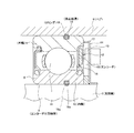
図1は、本発明の実施の形態の第1例を示している。回転側軌道輪である外輪9の外周面に係止凹溝18を、全周に亙って形成している。そして、この係止凹溝18に、Oリング19を装着している。このOリング19は、図1に示した自由状態での断面形状の直径が、前記係止凹溝18の深さよりも大きい。従って、前記外輪9をハブ6に内嵌する以前の状態で、前記Oリング19の外径側端部は、この外輪9の外周面よりも径方向外方に突出する。従って、このOリング19は、この外輪9を前記ハブ6に、締り嵌めで内嵌した状態で、前記係止凹溝18の底面とこのハブ6の内周面との間で弾性的に押圧される。この状態では、これら底面及び内周面と、前記Oリング19の内外両周面との間に大きな摩擦力が作用する。この結果、前記ハブ6と前記外輪9との嵌合部の締め代が低下乃至は消失しても、エンコーダ15を装着したこの外輪9が、車輪と共に回転する前記ハブ6に対し相対回転(クリープ)する事がなくなる。この結果、この車輪と前記エンコーダ15との回転速度を完全に一致させて、自動二輪車の車輪の回転速度検出に関する信頼性の向上を図れる。
[First example of embodiment]
FIG. 1 shows a first example of an embodiment of the present invention.
更に、本例の場合には、内輪10の内周面にも係止凹溝18aを形成し、この係止凹溝18aにもOリング19aを係止している。そして、前記内輪10を支持軸3に締り嵌めにより外嵌固定した状態で、このOリング19aを、この支持軸3の外周面と前記係止凹溝18aの底面との間で弾性的に押圧している。
本例の構造の場合には、前記Oリング19により、前記ハブ6に対する前記外輪9(及びこの外輪9に支持固定した前記エンコーダ15)の相対回転を防止すると共に、前記両Oリング19、19aにより、前記ハブ6の内周面と前記外輪9の外周面との間、並びに、前記内輪10の内周面と前記支持軸3の外周面との間のシール性確保を図っている。
その他の部分の構成及び作用は、前述の図5〜7に記載した従来構造とほぼ同様であるから、重複する説明は省略する。
Further, in the case of this example, a locking
In the case of the structure of this example, the O-
Since the configuration and operation of the other parts are almost the same as those of the conventional structure described in FIGS.
[実施の形態の第2例]
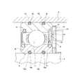
図2は、本発明の実施の形態の第2例を示している。本例の場合には、外輪9の外周面に2本の係止凹溝18、18を、内輪10の内周面に2本の係止凹溝18a、18aを、それぞれ形成し、これら各係止凹溝18、18aに、それぞれOリング19、19aを装着している。この様な本例の構造によれば、上述した実施の形態の第1例に比べて、ハブ6に対する外輪9のクリープ防止効果を向上させられると共に、このハブ6の内周面と前記外輪9の外周面との間、並びに、前記内輪10の内周面と支持軸3の外周面との間のシール性を、より十分に確保できる。
その他の部分の構成及び作用は、上述した実施の形態の第1例と同様であるから、重複する説明は省略する。
[Second Example of Embodiment]
FIG. 2 shows a second example of the embodiment of the present invention. In the case of this example, two locking
Since the configuration and operation of the other parts are the same as those in the first example of the above-described embodiment, redundant description is omitted.
[実施の形態の第3例]
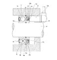
図3は、本発明の実施の形態の第3例を示している。本例の場合には、外輪9aと共に回転するエンコーダ15aを、組み合わせシールリング20を構成するスリンガ21の外側面に添着支持して、エンコーダ付玉軸受8aを構成している。又、支持軸3の中間部で、玉軸受4aを構成する内輪10aに隣接した部分にセンサホルダ22を外嵌固定し、このセンサホルダ22に保持した回転検出センサ13aの検出部を、前記エンコーダ15aの軸方向外側面に対向させている。
その他の部分の構成及び作用は、前述した実施の形態の第1例と同様であるから、重複する説明は省略する。
[Third example of embodiment]
FIG. 3 shows a third example of the embodiment of the present invention. In the case of this example, the
Since the configuration and operation of the other parts are the same as those in the first example of the above-described embodiment, redundant description is omitted.
[実施の形態の第4例]
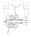
図4は、本発明の実施の形態の第4例を示している。本例の場合には、軸受ハウジング23の内径側に、特許請求の範囲に記載した中心軸部材である回転軸24を支持した、内輪回転型の構造に本発明を適用した場合に就いて示している。玉軸受4aの構成自体は、上述した実施の形態の第3例の場合と同様である。同様構成の玉軸受4aを使用して内輪回転型の構造を実現する為に本例の場合には、組み合わせシールリング20aを構成するスリンガ21aを内輪10aの端部外周面に、締り嵌めにより外嵌固定して、エンコーダ付玉軸受8bを構成している。又、シールリング16aを構成する芯金17aを外輪9aの端部内周面に、締り嵌めにより内嵌固定している。そして、エンコーダ15bを、前記スリンガ21aの外側面に、全周に亙って添着支持している。又、回転検出センサ13aは、前記軸受ハウジング23に設けた、保持フランジ25部分に支持している。更に、回り止め構造を、前記内輪10aの内周面と前記回転軸27の外周面との間に設けている。
その他の部分の構成及び作用は、前述した実施の形態の第1例と同様であるから、重複する説明は省略する。
[Fourth Example of Embodiment]
FIG. 4 shows a fourth example of the embodiment of the present invention. In the case of this example, the case where the present invention is applied to an inner ring rotating type structure in which the
Since the configuration and operation of the other parts are the same as those in the first example of the above-described embodiment, redundant description is omitted.
本発明を実施する場合に、エンコーダの材質は特に問わないが、プラスチック磁石製とする事が好ましい。この理由に就いて、以下に説明する。
一般的に永久磁石製のエンコーダを構成する為に、強磁性粉末であるストロンチウムフェライトを、バインダーであるニトリルゴム中に混入した磁性材料を使用する。又、この磁性材料を1対のロール間でシート状に成形する際に、前記強磁性粉末を配向した状態とする、所謂機械配向法を採用する。前記フェライト系の強磁性粉末の形状は、前記ロール同士の間で成形する際に配向され易い様に、面積に対して厚さ寸法を小さくしている。前記フェライト系の強磁性粉末は、この様な板状の形状とする為に、含有するバリウムの量が多く、残留磁束密度(Br)が磁場配向用ストロンチウムフェライト系の強磁性粉末に比べて低い反面、保磁力(bHc)及び固有保磁力(iHc)は、この磁場配向用ストロンチウムフェライト系の強磁性粉末に比べて高い。
When implementing the present invention, the material of the encoder is not particularly limited, but is preferably made of a plastic magnet. The reason will be described below.
In general, a magnetic material in which strontium ferrite, which is a ferromagnetic powder, is mixed in nitrile rubber, which is a binder, is used to construct an encoder made of a permanent magnet. In addition, when this magnetic material is formed into a sheet shape between a pair of rolls, a so-called mechanical orientation method is adopted in which the ferromagnetic powder is oriented. The ferrite-based ferromagnetic powder has a shape that is smaller in thickness than the area so that it can be easily oriented when formed between the rolls. Since the ferrite-based ferromagnetic powder has such a plate shape, it contains a large amount of barium, and the residual magnetic flux density (Br) is lower than that of the strontium ferrite-based ferromagnetic powder for magnetic field orientation. On the other hand, the coercive force (bHc) and the intrinsic coercive force (iHc) are higher than the strontium ferrite-based ferromagnetic powder for magnetic field orientation.
一方、本発明の対象となる、自動二輪車の車輪用回転速度検出装置は、小型の転がり軸受(玉軸受4、4a)にエンコーダ(15、15a、15b)を組み込む必要があり、使用可能なエンコーダの大きさが限られる。従って、上述の様な、機械配向法により強磁性粉末を配向させるフェライト含有ゴム磁石から成るエンコーダでは、被検出面から出入りする磁束の密度を十分に確保する事が難しい。この為、回転検出センサ(13、13a)の検出部に達する磁束の量を確保し、回転速度検出の信頼性を確保する為には、この回転検出センサの検出部と、前記エンコーダの被検出面との間の隙間(エアギャップ)を小さくするか、このエンコーダの円周方向の極数を少なくして、各極の面積を広くする必要があった。前記エアギャップを小さくする事は、走行時に加わるモーメント等により前記転がり軸受の構成部材等が弾性変形した場合に、前記回転検出センサの検出部と前記エンコーダの被検出面とが擦れ合う可能性が高くなる為、好ましくない。又、前記極数を少なくする事は、車輪が1回転する間に行える、前記回転速度検出の回数が少なくなり、ABS制御の迅速性確保の面から不利になる。
On the other hand, the rotational speed detection device for a motorcycle wheel, which is an object of the present invention, needs to incorporate an encoder (15, 15a, 15b) into a small rolling bearing (
これに対して、前記エンコーダを、強磁性粉末をバインダーである合成樹脂中に混入したプラスチック磁石製とすれば、ゴム磁石に比べて磁気特性の向上を図る事ができる。具体的には、エンコーダの被検出面から出入りする磁束の密度を高くして、このエンコーダの被検出面と回転検出センサの検出部との間の隙間大きくしたり、このエンコーダの円周方向の極数を多くしたりしても、この検出部に達する磁束の量を多くできる。そして、回転検出センサの検出部とエンコーダの被検出面とが擦れ合う事を防止し、しかも、ABS制御の迅速性確保を図れる。尚、プラスチック磁石製のエンコーダを添着支持する芯金(17、17a)或いはスリンガ(21、21a)の材質は、このエンコーダの磁気特性を低下させず、且つ、必要とする耐食性を有する磁性金属板を使用する。この様な条件を満たす磁性金属板としては、フェライト系ステンレス鋼(SUS430等)、マルテンサイト系ステンレス鋼(SUS410等)等が挙げられる。 On the other hand, if the encoder is made of a plastic magnet in which ferromagnetic powder is mixed in a synthetic resin as a binder, the magnetic characteristics can be improved as compared with a rubber magnet. Specifically, the density of the magnetic flux entering and exiting the detected surface of the encoder is increased to increase the gap between the detected surface of the encoder and the detection portion of the rotation detection sensor, or in the circumferential direction of the encoder. Even if the number of poles is increased, the amount of magnetic flux reaching the detection unit can be increased. And it can prevent that the detection part of a rotation detection sensor and the to-be-detected surface of an encoder rub against each other, and can aim at ensuring quickness of ABS control. The material of the metal core (17, 17a) or slinger (21, 21a) for attaching and supporting the plastic magnet encoder does not deteriorate the magnetic properties of the encoder and has the necessary corrosion resistance. Is used. Examples of the magnetic metal plate satisfying such conditions include ferritic stainless steel (SUS430 and the like), martensitic stainless steel (SUS410 and the like), and the like.
この様な芯金或いはスリンガに、プラスチック磁石製のエンコーダを添着固定するには、先ず、予め接着剤を塗布した芯金或いはスリンガをコアにして、磁性材料(強磁性粉末を混入した溶融合成樹脂)をインサート成形する。このインサート成形は、ディスクゲート方式の射出成形機により行なう事が好ましい。この理由は、溶融した磁性材料がディスク状に拡がってから、金型内に存在する、前記エンコーダを成形する為のキャビティ内に流入する際に、前記溶融した磁性材料中に含有する鱗片状の強磁性粉末が、得られるエンコーダの被検出面に対して平行に配向する為である。又、得られるエンコーダの周方向の一部に、異なる部分から送られて来る溶融樹脂同士がぶつかる事で生じるウェルドが発生する事を防止できて、優れた強度を有するエンコーダを得られる。 In order to attach and fix an encoder made of a plastic magnet to such a core metal or slinger, first, a core metal or slinger previously coated with an adhesive is used as a core, and a magnetic material (a molten synthetic resin mixed with ferromagnetic powder) is used. ) Is insert molded. This insert molding is preferably performed by a disk gate type injection molding machine. The reason for this is that when the molten magnetic material spreads in a disk shape and then flows into the cavity for molding the encoder, the scale-like material contained in the molten magnetic material is present in the mold. This is because the ferromagnetic powder is oriented parallel to the detected surface of the encoder obtained. In addition, it is possible to prevent the occurrence of welds caused by the molten resins sent from different parts colliding with each other in the circumferential direction of the obtained encoder, and an encoder having excellent strength can be obtained.
尚、上述の様にして行う、このエンコーダの射出成形時に、前記金型に、前記キャビティ(内で成形されるエンコーダ)の厚さ方向に磁場を加えれば(磁場成形すれば)、得られるエンコーダ中の強磁性粉末の異方性をより完全に近くできて、着磁後のエンコーダの被検出面から出入りする磁束の量を、より多くできる。
これに対して、サイドゲート方式の射出成形機を使用した場合には、前記ウェルドの発生が避けられない。このウェルド部分では、或る程度温度が低下して粘性が高くなった溶融樹脂同士がぶつかり合うので、機械的強度が低下するだけでなく、溶融樹脂中に混入した強磁性粉末の向きが変わる事に対する抵抗が大きくなる。この為、仮に磁場成形を行ったとしても、前記ウェルド部及びその近傍部分で、前記強磁性粉末の配向状態を十分に異方化する事は難しくなる。この結果、このウェルド部及びその近傍部分の磁場特性が低下し、得られるエンコーダにより構成した回転速度検出装置による、車輪の回転速度検出に関する信頼性確保の面から不利になる。
When the encoder is injection-molded as described above, a magnetic field is applied to the mold in the thickness direction of the cavity (encoder formed therein) (if the magnetic field is molded), the resulting encoder The anisotropy of the ferromagnetic powder therein can be made closer to perfection, and the amount of magnetic flux entering and exiting from the detected surface of the encoder after magnetization can be increased.
On the other hand, when a side gate type injection molding machine is used, the occurrence of the weld is inevitable. In this weld part, molten resins whose viscosity has been lowered to a certain extent collide with each other, so that not only the mechanical strength is lowered, but also the direction of the ferromagnetic powder mixed in the molten resin is changed. The resistance to increases. For this reason, even if magnetic field shaping is performed, it is difficult to sufficiently anisotropy the orientation state of the ferromagnetic powder in the weld and its vicinity. As a result, the magnetic field characteristics of the weld portion and the vicinity thereof are deteriorated, which is disadvantageous in terms of ensuring the reliability related to the detection of the rotational speed of the wheel by the rotational speed detection device configured by the obtained encoder.
前記エンコーダを、前記ディスクゲート方式の射出成形機により、磁場成形を併用しつつ射出成形する場合には、前記金型のキャビティ内に、前記強磁性粉末を混入した溶融樹脂を充填して前記エンコーダを成形した後、この金型から取り出す以前に、この金型内で冷却する過程で脱磁を行う。この脱磁は、この金型に、前記射出成形時と逆方向の磁界を加える事により行う。この脱磁を行いつつ、前記エンコーダを冷却させた後、ゲート部の外径側端部を切除して、このエンコーダを前記金型から取り出す。そして、接着剤を或る程度硬化させてから、前記エンコーダを更に脱磁する。この更なる脱磁は、オイルコンデンサ式等の脱磁機を用いて行い、このエンコーダの残留磁束密度を、2mT以下、より好ましくは1mT以下にまで低下させる。次いで、前記ゲート部に繋がっている余肉部を除去(トリミング)すると共に、恒温槽等で一定温度、一定時間加熱して、接着剤を完全に硬化させる。尚、この接着剤を硬化させる事は、前記芯金或いはスリンガを、高周波加熱等により短時間だけ加熱する事でも行える。そして、最後に、前記エンコーダを着磁ヨークと重ね合わせて、このエンコーダを軸方向に、且つ、着磁方向を円周方向に関して交互に且つ等間隔で反転させた状態で着磁し、前記エンコーダの被検出面である軸方向側面に、S極とN極とを、交互に、且つ、等間隔で配置する。 When the encoder is injection-molded by the disk gate type injection molding machine while using magnetic field molding together, the cavity of the mold is filled with a molten resin mixed with the ferromagnetic powder and the encoder After demolding, before removing from the mold, demagnetization is performed in the process of cooling in the mold. This demagnetization is performed by applying a magnetic field in the opposite direction to that during the injection molding to this mold. The encoder is cooled while performing the demagnetization, and then the outer diameter side end of the gate portion is cut out and the encoder is taken out from the mold. Then, after the adhesive is cured to some extent, the encoder is further demagnetized. This further demagnetization is performed by using a demagnetizer such as an oil capacitor type, and the residual magnetic flux density of this encoder is reduced to 2 mT or less, more preferably 1 mT or less. Next, the surplus portion connected to the gate portion is removed (trimmed), and the adhesive is completely cured by heating at a constant temperature for a predetermined time in a thermostatic bath or the like. The adhesive can be cured by heating the core bar or slinger for a short time by high frequency heating or the like. Finally, the encoder is superposed on the magnetizing yoke, and the encoder is magnetized in the axial direction and the magnetizing direction is alternately reversed at equal intervals with respect to the circumferential direction. S poles and N poles are alternately arranged at equal intervals on the side surface in the axial direction which is the detected surface.
尚、前記エンコーダを構成する磁性材料中の強磁性粉末としては、磁気特性や耐候性を考慮して、ストロンチウムフェライト、バリウムフェライト等のフェライト系強磁性粉末、サマリウム−鉄−窒素、サマリウム−コバルト、ネオジウム−鉄−ボロン等の希土類強磁性粉末が、好ましく使用できる。これらの強磁性粉末は、それぞれ単独で、或いは複数種類組み合わせて使用する。尚、高い磁気特性(BHmaxで2.0MGOe超)が必要な場合には希土類強磁性粉末を使用し、低い磁気特性(BHmaxで1.6〜2.0MGOe)で良い場合には、コストを考慮して、フェライト系強磁性粉末を主成分とする配合が好ましい。又、磁性材料中の強磁性粉末の含有量は、強磁性粉末の種類により異なるが、70〜92質量%の範囲であれば実用上問題はない。 As the ferromagnetic powder in the magnetic material constituting the encoder, in consideration of magnetic properties and weather resistance, ferrite ferromagnetic powder such as strontium ferrite and barium ferrite, samarium-iron-nitrogen, samarium-cobalt, Rare earth ferromagnetic powders such as neodymium-iron-boron can be preferably used. These ferromagnetic powders are used singly or in combination. When high magnetic properties (BHmax> 2.0 MGOe) are required, rare earth ferromagnetic powder is used. When low magnetic properties (BHmax 1.6 to 2.0 MGOe) are acceptable, the cost is considered. Thus, a blend containing ferrite-based ferromagnetic powder as a main component is preferable. The content of the ferromagnetic powder in the magnetic material varies depending on the type of the ferromagnetic powder, but there is no practical problem if it is in the range of 70 to 92% by mass.
バインダーである合成樹脂は、ポリアミド樹脂に耐衝撃性向上剤を添加したものが、好ましく使用できる。ポリアミド樹脂は、耐疲労性及び耐熱性に優れる合成樹脂であり、得られるエンコーダの耐熱衝撃性を向上させる効果がある。
又、前記耐衝撃性向上剤は、振動や衝撃を緩和する作用を有する弾性材料であり、以下に述べる合成樹脂やゴム材料が、好ましく使用できる。このうち、前記耐衝撃性向上剤として使用する合成樹脂は、変性ポリアミド樹脂が好ましい。
この変性ポリアミド樹脂は、ポリアミド樹脂から成るハードセグメントと、ポリエステル成分及びポリエーテル成分のうちの少なくとも一方から成るソフトセグメントとを有するブロック共重合体であり、市販品としてはポリアミド6、ポリアミド11、ポリアミド12等をハードセグメントとする変性ポリアミド樹脂が知られている。
又、前記耐衝撃性向上剤として使用するゴム材料としては、スチレンブタジエンゴム、アクリルゴム、アクリロニトリルブタジエンゴム、カルボキシル変性アクリロニトリルブタジエンゴム、シリコンゴム、クロロプレンゴム、水素添加ニトリルゴム、カルボシキル変性水素添加ニトリルゴム、カルボキシル変性スチレンブタジエンゴムから成る粒子が好ましく、それぞれ単独で、または複数種類を組み合わせて使用する。
更に、前記耐衝撃性向上剤として、エチレンプロピレン非共役ジエンゴム(EPDM)、無水マレイン酸変性エチレンプロピレン非共役ジエンゴム(EPDM)、エチレン/アクリレート共重合体、アイオノマー等も使用可能である。
これら耐衝撃性向上剤の添加量は、ポリアミド樹脂との合計量に対し、5〜50質量%が好ましく、10〜40質量%がより好ましい。添加量が5質量%未満では、少な過ぎて耐衝撃性の改善効果が不十分となる。これに対して添加量が50質量%を超えると、耐衝撃性は向上するものの、相対的にバインダとしての主体となる、通常のポリアミド樹脂の量が少なくなり、引張強度等が低下して、前記エンコーダとしての強度確保が難しくなる。
As the synthetic resin as a binder, a polyamide resin added with an impact resistance improver can be preferably used. The polyamide resin is a synthetic resin excellent in fatigue resistance and heat resistance, and has an effect of improving the thermal shock resistance of the encoder obtained.
The impact resistance improver is an elastic material having a function of relaxing vibrations and impacts, and synthetic resins and rubber materials described below can be preferably used. Of these, the synthetic resin used as the impact resistance improver is preferably a modified polyamide resin.
This modified polyamide resin is a block copolymer having a hard segment composed of a polyamide resin and a soft segment composed of at least one of a polyester component and a polyether component. As commercial products,
The rubber materials used as the impact resistance improver include styrene butadiene rubber, acrylic rubber, acrylonitrile butadiene rubber, carboxyl-modified acrylonitrile butadiene rubber, silicon rubber, chloroprene rubber, hydrogenated nitrile rubber, and carboxyl-modified hydrogenated nitrile rubber. Particles made of carboxyl-modified styrene butadiene rubber are preferable, and are used alone or in combination of a plurality of types.
Furthermore, ethylene propylene non-conjugated diene rubber (EPDM), maleic anhydride-modified ethylene propylene non-conjugated diene rubber (EPDM), ethylene / acrylate copolymer, ionomer, and the like can be used as the impact resistance improver.
5-50 mass% is preferable with respect to the total amount with a polyamide resin, and, as for the addition amount of these impact resistance improvers, 10-40 mass% is more preferable. If the addition amount is less than 5% by mass, the effect of improving the impact resistance becomes insufficient because of too little. On the other hand, when the addition amount exceeds 50% by mass, although the impact resistance is improved, the amount of a normal polyamide resin which is a main component as a binder is relatively reduced, and the tensile strength and the like are reduced. Ensuring strength as the encoder becomes difficult.
又、このエンコーダと、前記芯金或いはスリンガとを接着する為の接着剤としては、溶剤での稀釈が可能で、2段階に近い硬化反応が進む、フェノール樹脂系接着剤、エポキシ樹脂系接着剤等が好ましい。これらの接着剤は、耐熱性、耐薬品性、ハンドリング性等にも優れるという利点を有する。
尚、前記エンコーダと前記芯金或いはスリンガとを接着固定する作業は、必ずしも、前述の様に、このエンコーダを前記金型内で射出成形するのと同時に行う必要はない。単独で円輪状に射出成形したエンコーダを、金型から取り出してから、前記芯金或いはスリンガと接着固定した後、このエンコーダの被検出面を多極に着磁しても良い。
Moreover, as an adhesive for adhering the encoder to the core metal or slinger, it is possible to dilute with a solvent, and a phenol resin adhesive or an epoxy resin adhesive in which a curing reaction proceeds in two steps. Etc. are preferred. These adhesives have the advantage of being excellent in heat resistance, chemical resistance, handling properties and the like.
Note that the operation of bonding and fixing the encoder and the core metal or slinger is not necessarily performed simultaneously with the injection molding of the encoder in the mold as described above. An encoder that is independently injection-molded into an annular shape may be taken out of the mold, and after being bonded and fixed to the core metal or slinger, the detected surface of the encoder may be magnetized in multiple poles.
1 ホーク
2 支持板
3 支持軸
4、4a 玉軸受
5a、5b、5c 内輪間座
6 ハブ
7 ホイール
8、8a、8b エンコーダ付玉軸受
9、9a 外輪
10、10a 内輪
11 玉
12 エンコーダ付シールリング
13、13a 回転検出センサ
14 ホルダ部材
15、15a、15b エンコーダ
16、16a シールリング
17、17a 芯金
18、18a 係止凹溝
19、19a Oリング
20、20a 組み合わせシールリング
21、21a スリンガ
22 センサホルダ
23 軸受ハウジング
24 回転軸
25 保持フランジ
DESCRIPTION OF SYMBOLS 1 Hawk 2
Claims (1)
このうちの中心軸部材は車輪と同心に設けられており、
前記外径側部材は、この中心軸部材の周囲に、この中心軸部材と同心に設けられており、
前記転がり軸受は、前記外径側部材の内周面と前記中心軸部材の外周面との間に設けられており、
前記エンコーダは、被検出面の特性を円周方向に関して交互に変化させたものであり、
前記回転検出センサは、前記エンコーダの回転に伴って変化する信号を出力するものであり、
前記転がり軸受は、外周面に内輪軌道を有し、前記中心軸部材に外嵌固定された内輪と、内周面に外輪軌道を有し、前記外径側部材に内嵌固定された外輪と、この外輪軌道と前記内輪軌道との間に転動自在に設けられた複数個の転動体とを備えたものであり、
前記エンコーダは、前記内輪と前記外輪とのうちの一方で前記車輪と共に回転する軌道輪である回転側軌道輪の内外両周面のうち、前記中心軸と前記外径側部材とのうちの一方で前記車輪と共に回転する部材である、回転側部材と嵌合する嵌合側周面に対し逆側に存在する非嵌合側周面の端部に、この回転側軌道輪と同心に支持固定されており、
前記回転検出センサは、検出部を前記エンコーダの被検出面に対向させた状態で、前記中心軸部材と前記外径側部材とのうちの他方で回転しない部材である静止側部材の一部に支持固定している
自動二輪車の車輪用回転速度検出装置に於いて、
前記回転側軌道輪の嵌合側周面に全周に亙って形成した係止凹溝に、自由状態での断面形状の直径がこの係止凹溝の深さよりも大きいOリングを装着し、前記回転側軌道輪を前記回転側部材に嵌合した状態でこのOリングを、前記係止凹溝の底面とこの回転側部材の周面との間で弾性的に押圧して、前記回転側軌道輪がこの回転側部材に対し回転する事を防止した事を特徴とする自動二輪車の車輪用回転速度検出装置。 A center shaft member, an outer diameter side member, a rolling bearing, an encoder, and a rotation detection sensor;
Of these, the central shaft member is provided concentrically with the wheel,
The outer diameter side member is provided concentrically with the central shaft member around the central shaft member,
The rolling bearing is provided between an inner peripheral surface of the outer diameter side member and an outer peripheral surface of the central shaft member,
The encoder is obtained by alternately changing the characteristics of the surface to be detected with respect to the circumferential direction,
The rotation detection sensor outputs a signal that changes as the encoder rotates,
The rolling bearing has an inner ring raceway on an outer peripheral surface and is fitted and fixed to the central shaft member, and an outer ring has an outer ring raceway on an inner peripheral surface and is fitted and fixed to the outer diameter side member. And a plurality of rolling elements provided between the outer ring raceway and the inner ring raceway so as to be freely rollable.
The encoder is one of the central axis and the outer-diameter side member of both the inner and outer peripheral surfaces of a rotation-side raceway that is a raceway that rotates with the wheel on one of the inner race and the outer race. At the end of the non-fitting side peripheral surface that exists on the opposite side to the fitting side peripheral surface that fits with the rotation side member, which is a member that rotates together with the wheel, it is supported and fixed concentrically with the rotating side raceway. Has been
The rotation detection sensor is a part of the stationary side member that is a member that does not rotate on the other of the central shaft member and the outer diameter side member with the detection unit facing the detection surface of the encoder. In the rotational speed detection device for a motorcycle wheel that is supported and fixed,
An O-ring in which the diameter of the cross-sectional shape in the free state is larger than the depth of the locking groove is attached to the locking groove formed over the entire circumference on the fitting side peripheral surface of the rotating side race. The O-ring is elastically pressed between the bottom surface of the locking groove and the peripheral surface of the rotating side member in a state where the rotating side race is fitted to the rotating side member, and the rotation is performed. A rotational speed detecting device for a wheel of a motorcycle, wherein the side raceway is prevented from rotating relative to the rotating side member.
Priority Applications (9)
| Application Number | Priority Date | Filing Date | Title |
|---|---|---|---|
| JP2011031849A JP2012172686A (en) | 2011-02-17 | 2011-02-17 | Rotational speed detection device for wheel of motorcycle |
| PCT/JP2011/053830 WO2011105366A1 (en) | 2010-02-23 | 2011-02-22 | Ball bearing equipped with encoder for detecting rotational speed of wheel of two-wheeled motor vehicle, and device for detecting rotational speed of wheel of two-wheeled motor vehicle, the device using the ball bearing |
| EP11747327A EP2541088A1 (en) | 2010-02-23 | 2011-02-22 | Ball bearing equipped with encoder for detecting rotational speed of wheel of two-wheeled motor vehicle, and device for detecting rotational speed of wheel of two-wheeled motor vehicle, the device using the ball bearing |
| CN2011800034939A CN102483094A (en) | 2010-02-23 | 2011-02-22 | Ball bearing equipped with encoder for detecting rotational speed of wheel of two-wheeled motor vehicle, and device for detecting rotational speed of wheel of two-wheeled motor vehicle, the device using the ball bearing |
| US13/391,914 US20120204638A1 (en) | 2010-02-23 | 2011-02-22 | Ball bearing with a rotational speed detection encoder for a motorcycle and a rotational speed detection device for a motorcycle using this encoder |
| PCT/JP2011/065052 WO2012014622A1 (en) | 2010-07-28 | 2011-06-30 | Wheel support structure for two-wheeled vehicle |
| CN2011800034958A CN102483095A (en) | 2010-07-28 | 2011-06-30 | Wheel support structure for two-wheeled vehicle |
| EP11812215.9A EP2600017A1 (en) | 2010-07-28 | 2011-06-30 | Wheel support structure for two-wheeled vehicle |
| US13/391,957 US8636417B2 (en) | 2010-07-28 | 2011-06-30 | Wheel support structure for motorcycle |
Applications Claiming Priority (1)
| Application Number | Priority Date | Filing Date | Title |
|---|---|---|---|
| JP2011031849A JP2012172686A (en) | 2011-02-17 | 2011-02-17 | Rotational speed detection device for wheel of motorcycle |
Publications (1)
| Publication Number | Publication Date |
|---|---|
| JP2012172686A true JP2012172686A (en) | 2012-09-10 |
Family
ID=46975794
Family Applications (1)
| Application Number | Title | Priority Date | Filing Date |
|---|---|---|---|
| JP2011031849A Withdrawn JP2012172686A (en) | 2010-02-23 | 2011-02-17 | Rotational speed detection device for wheel of motorcycle |
Country Status (1)
| Country | Link |
|---|---|
| JP (1) | JP2012172686A (en) |
Cited By (3)
| Publication number | Priority date | Publication date | Assignee | Title |
|---|---|---|---|---|
| CN108317180A (en) * | 2018-01-15 | 2018-07-24 | 东南大学 | Rotor testbed bearing positioning and bearing pre-tightening device |
| WO2019124152A1 (en) * | 2017-12-18 | 2019-06-27 | 日本電産株式会社 | In-wheel motor |
| JP7281422B2 (en) | 2020-01-15 | 2023-05-25 | 株式会社シマノ | fishing reel |
-
2011
- 2011-02-17 JP JP2011031849A patent/JP2012172686A/en not_active Withdrawn
Cited By (4)
| Publication number | Priority date | Publication date | Assignee | Title |
|---|---|---|---|---|
| WO2019124152A1 (en) * | 2017-12-18 | 2019-06-27 | 日本電産株式会社 | In-wheel motor |
| CN108317180A (en) * | 2018-01-15 | 2018-07-24 | 东南大学 | Rotor testbed bearing positioning and bearing pre-tightening device |
| CN108317180B (en) * | 2018-01-15 | 2020-01-03 | 东南大学 | Rotor experiment table supporting position adjusting and bearing pre-tightening device |
| JP7281422B2 (en) | 2020-01-15 | 2023-05-25 | 株式会社シマノ | fishing reel |
Similar Documents
| Publication | Publication Date | Title |
|---|---|---|
| WO2011105366A1 (en) | Ball bearing equipped with encoder for detecting rotational speed of wheel of two-wheeled motor vehicle, and device for detecting rotational speed of wheel of two-wheeled motor vehicle, the device using the ball bearing | |
| WO2009098851A1 (en) | Wheel bearing device with rotation detector | |
| JP2006313117A (en) | Manufacturing method of encoder | |
| JP2012172686A (en) | Rotational speed detection device for wheel of motorcycle | |
| JP4899404B2 (en) | Rolling bearing with encoder | |
| JP2007316024A (en) | Rolling bearing | |
| JP4821123B2 (en) | Magnetic encoder and rolling bearing unit | |
| JP2007333142A (en) | Rolling bearing | |
| JP2012172692A (en) | Rotational speed detection device for wheel of two-wheeled motor vehicle | |
| JP4742796B2 (en) | Rolling bearing unit with rotation detector | |
| JP4952087B2 (en) | Rolling bearing unit | |
| JP2005214874A (en) | Encoder, and rolling bearing equipped with encoder | |
| JP2011247336A (en) | Ball bearing with wheel rotation speed detecting magnetic encoder for motorcycle | |
| JP2007101443A (en) | Rolling bearing unit with magnetic encoder, and manufacturing method therefor | |
| JP2007333184A (en) | Rolling bearing | |
| KR102233658B1 (en) | How to manufacture a hub unit | |
| JP2012137188A (en) | Rolling bearing with encoder | |
| JP2006177756A (en) | Manufacturing method of magnetic encoder | |
| JP5274042B2 (en) | Wheel bearing device with rotation detector | |
| JP5002992B2 (en) | Rolling bearing with encoder | |
| JP2007163397A (en) | Magnetized pulser ring | |
| JP2007198743A (en) | Magnetic encoder and rolling bearing unit | |
| JP2023029010A (en) | Encoder manufacturing method | |
| JP2005016990A (en) | Encoder for wheel rotation speed detection | |
| JP2013181859A (en) | Magnetized pulser ring and rolling bearing deice provided with the same |
Legal Events
| Date | Code | Title | Description |
|---|---|---|---|
| A300 | Withdrawal of application because of no request for examination |
Free format text: JAPANESE INTERMEDIATE CODE: A300 Effective date: 20140513 |