JP2012170706A - Electric kettle - Google Patents
Electric kettle Download PDFInfo
- Publication number
- JP2012170706A JP2012170706A JP2011036841A JP2011036841A JP2012170706A JP 2012170706 A JP2012170706 A JP 2012170706A JP 2011036841 A JP2011036841 A JP 2011036841A JP 2011036841 A JP2011036841 A JP 2011036841A JP 2012170706 A JP2012170706 A JP 2012170706A
- Authority
- JP
- Japan
- Prior art keywords
- steam
- kettle
- passage
- liquid
- lid
- Prior art date
- Legal status (The legal status is an assumption and is not a legal conclusion. Google has not performed a legal analysis and makes no representation as to the accuracy of the status listed.)
- Withdrawn
Links
Images


Abstract
Description
本発明は、電気ケトルに関し、詳しくはケトル内で発生した蒸気をケトルの注ぎ口側から排出させることができる安全性の高い電気ケトルに関する。 The present invention relates to an electric kettle, and more particularly to a highly safe electric kettle that can discharge steam generated in the kettle from the spout side of the kettle.
電気ケトルは、持ち運びが簡単で手軽にお湯を沸かすことができるものとして広く普及してきている。この電気ケトルは、例えば、所定量の水などを入れて加熱する電熱部を有するケトル本体と、このケトル本体の電熱部へ電力を供給する外部電源コードが接続された給電台とを有し、この給電台にケトル本体をセットして、電源スイッチをオンすることによって、湯などを沸かすことができる構成となっている。 Electric kettles have become widespread as being easy to carry and capable of boiling hot water easily. This electric kettle has, for example, a kettle body having an electric heating part for heating a predetermined amount of water and the like, and a power supply base connected to an external power cord for supplying electric power to the electric heating part of the kettle main body, By setting the kettle body on this power supply stand and turning on the power switch, hot water can be boiled.
また、蓋が本体から着脱可能であり、ケトル本体を蓋体によって密封してケトルが転倒した際に内容物が流失しないような構成のものも知られている。このような電気ケトルにおいては、沸騰時にケトル本体内で発生した蒸気を外部に排出するための構造が蓋体内に設けられ、蒸気は蓋体上部に設けられた蒸気口から排出されるようにされている。例えば、下記特許文献1に開示された電気ケトルの蓋体の上面には外部に蒸気を排出するための蒸気孔が形成され、蓋体の内部には、蒸気を蒸気孔に導くための蒸気通路が形成されている。 There is also known a configuration in which the lid is detachable from the main body, and the contents are not washed away when the kettle main body is sealed with the lid body and the kettle falls. In such an electric kettle, a structure for discharging the steam generated in the kettle body to the outside at the time of boiling is provided in the lid, and the steam is discharged from a steam port provided in the upper part of the lid. ing. For example, a steam hole for discharging steam to the outside is formed in the upper surface of the lid of the electric kettle disclosed in Patent Document 1 below, and a steam passage for guiding the steam to the steam hole in the lid Is formed.
下記特許文献1に開示された電気ケトルは、蒸気通路の蒸気がセンサ室に余裕を残して入り込んで更新性よくセンサに接触し、結露水の多量発生なくスムーズに気化発散されるようにするため、ヒータにより湯沸かしを行う器体と、この器体の蓋体と、器体の外まわりに設けたハンドルと、器体内で発生する蒸気を導入して蒸気センサに接触させるハンドル上部のセンサ室と、を備え、器体側からハンドル上部内に蒸気を導入し排出を図る蒸気通路の途中からセンサ室を分岐させて、蒸気通路よりセンサ室に分岐し流入する蒸気が蒸気センサに接触するようにし、前記蒸気通路とセンサ室との蒸気通路上流側の分岐点に、蒸気通路下流側に延びて蒸気通路からセンサ室への蒸気の流入域を規制するように蒸気通路側とセンサ室側とを部分的に仕切る仕切り壁が設けられている。 In the electric kettle disclosed in Patent Document 1 below, steam in the steam passage enters the sensor chamber leaving a margin and comes into contact with the sensor with good renewability so that it can be smoothly vaporized and diffused without generating a large amount of condensed water. , A container body that performs boiling with a heater, a lid body of the container body, a handle provided around the exterior of the container body, a sensor chamber at an upper part of the handle that introduces steam generated in the container body and contacts the steam sensor; The sensor chamber is branched from the middle of the steam passage for introducing and discharging steam into the upper part of the handle from the container side, so that the steam flowing from the steam passage into the sensor chamber contacts the steam sensor, The steam passage side and the sensor chamber side are partially connected to the branch point on the upstream side of the steam passage between the steam passage and the sensor chamber so as to restrict the inflow region of the steam from the steam passage to the sensor chamber. In Partition wall cut is provided.
このような構成をとることにより、蓋体により、湯沸かし時に器体から生じる蒸気を位置や範囲を制限して外部に放出させながら、外部への放出が制限されることにより生じる蒸気圧にて、器体で発生する蒸気の一部を器体側からハンドル側の蒸気通路に流入させて排出させる途中で、蒸気通路から分岐したセンサ室にも流入させて蒸気センサに接触させて沸騰を検知させるのに、蒸気通路とセンサ室との蒸気通路上流側の分岐点に蒸気通路下流側に向け延びる仕切り壁によりセンサ室への蒸気の流入域を規制し、センサ室には仕切り域を残した片寄った範囲から適量流入させるので、結露水が過剰にならずに流入蒸気との拮抗なくスムーズに蒸気通路に戻しながら、センサ室内に片寄って流入した蒸気に反片寄り側に回り込む流れを与えながら更新性よく蒸気センサに接触させることができる。 By taking such a configuration, with the vapor pressure generated by limiting the discharge to the outside while limiting the position and range of the steam generated from the container body when boiling the water by the lid body, While part of the steam generated in the container flows into the steam passage on the handle side from the container side and is discharged, it also flows into the sensor chamber branched from the steam passage and makes contact with the steam sensor to detect boiling. In addition, a partition wall extending toward the downstream side of the steam passage is regulated at a branch point upstream of the steam passage between the steam passage and the sensor chamber, and the inflow region of the steam into the sensor chamber is regulated, and the sensor chamber is left with a partition region left behind. Since an appropriate amount of water is allowed to flow in from the range, the flow of water flowing inwardly into the sensor chamber should not be given to the opposite side of the sensor chamber while smoothly returning to the steam passage without causing competition with the inflowing steam without excessive condensation. Et updated good can be brought into contact with the vapor sensor.
上記特許文献1に記載の電気ケトルにおいては、ケトル内部で発生した蒸気を蒸気通路を通じて効率よく蒸気センサに導くとともに、抽出口や蓋体の操作部から離れた蓋体後部から蒸気が放出されるので、人の手や顔が位置する機会の多い抽出口側から離れた安全な位置から蒸気を外部に放出し、使用上の安全を図るとされている。 In the electric kettle described in Patent Document 1, the steam generated inside the kettle is efficiently guided to the steam sensor through the steam passage, and the steam is discharged from the rear part of the lid body away from the extraction port and the operation part of the lid body. Therefore, it is said that steam is discharged to the outside from a safe position away from the extraction port side where human hands and face are often located, thereby ensuring safety in use.
しかし、上記特許文献1に記載の電気ケトルを含む従来のケトルは、蒸気を排出する蒸気孔が蓋体の上側に形成されていることから、沸騰中もしくは沸騰直後に蓋体に設けられた開閉スイッチを操作したり、注ぐために手を添えたりしてしまったとき、蓋体上部から噴出する蒸気によりやけどをするおそれがあった。特に、ケトル本体を蓋体によって密封する構成の電気ケトルは、蒸気口が設けられている蓋体の上面に、蓋体の着脱機構の操作部や抽出路の開閉機構の操作部も設けられることが多いため、誤って使用者が蒸気に触れてしまう危険性がある。一方で、抽出路側には操作部等が配置されていないため、使用者が誤って手を触れてしまう危険性が比較的低くなっている。 However, since the conventional kettle including the electric kettle described in Patent Document 1 has a steam hole for discharging steam formed on the upper side of the lid, the opening / closing provided in the lid during or immediately after boiling When operating the switch or putting a hand to pour it, there was a risk of burns from the steam that spouted from the top of the lid. In particular, an electric kettle configured to seal the kettle body with a lid body is provided with an operation portion of a lid attachment / detachment mechanism and an extraction path opening / closing mechanism operation portion on the upper surface of the lid body provided with a steam port. Therefore, there is a risk that the user may accidentally touch the steam. On the other hand, since no operation unit or the like is arranged on the extraction path side, there is a relatively low risk that the user will accidentally touch the hand.
本発明は、このような従来技術が抱える課題を解決するためになされたもので、ケトル内で発生した蒸気をケトルの注ぎ口側から排出させることにより、使用者が誤って蒸気に触れる可能性が低く、安全性の高い電気ケトルを提供することを目的とする。 The present invention was made in order to solve such problems of the conventional technology, and by discharging the steam generated in the kettle from the pouring side of the kettle, the user may accidentally touch the steam. The purpose is to provide an electric kettle that is low in safety and high in safety.
上記目的を達成するために、請求項1に記載の電気ケトルは、上方に開口を有すると共に前記開口の一部に外側に屈曲した注ぎ口が形成され、内部に所定量の液体が収容されるケトル本体と、前記ケトル本体に収容された前記液体を加熱する加熱手段と、前記ケトル本体の前記開口を覆う着脱自在な蓋体と、を有する電気ケトルにおいて、前記蓋体は、前記ケトル本体に収容された前記液体を前記ケトル本体の前記注ぎ口と対応する位置に形成された注水口を経て供給するための液体供給路と、前記液体供給路と前記ケトル本体との間に形成された、前記液体を前記液体供給路に導くための液体供給口と、前記液体供給口の開け閉めを行う開閉弁と、前記ケトル本体内で発生した蒸気を導通させる蒸気通路と、前記蒸気通路と前記ケトル本体との間に形成された、蒸気を蒸気通路に導くための蒸気導通口と、を有し、前記蒸気通路は前記液体供給路の前記開閉弁の下流側と連通され、前記蒸気通路を導通された蒸気は、前記液体供給路を通って、前記注水口から外部に排出されることを特徴とする。 In order to achieve the above object, the electric kettle according to claim 1 has an opening on the upper side, and a spout bent outward is formed in a part of the opening, and a predetermined amount of liquid is accommodated therein. An electric kettle having a kettle body, heating means for heating the liquid contained in the kettle body, and a detachable lid that covers the opening of the kettle body, wherein the lid is attached to the kettle body Formed between the liquid supply path and the kettle body, the liquid supply path for supplying the stored liquid through the water inlet formed at a position corresponding to the pouring opening of the kettle body, A liquid supply port for guiding the liquid to the liquid supply path; an on-off valve that opens and closes the liquid supply port; a vapor passage that conducts vapor generated in the kettle body; the vapor passage and the kettle Body A vapor conduction port formed between the two and connected to the downstream side of the on-off valve of the liquid supply passage and conducted through the vapor passage. Vapor is discharged from the water inlet through the liquid supply path.
請求項2の発明は、請求項1に記載の電気ケトルにおいて、前記ケトル本体には前記注ぎ口と対向する側に取っ手部が形成され、前記取っ手部の前記蓋体が取り付けられる側には前記取っ手部と連通する開孔が形成され、前記蓋体が装着される側の前記取っ手部の内部には蒸気センサーが設けられ、前記蓋体には前記蒸気センサーと対向する位置に蒸気口が形成され、前記蒸気通路は、前記ケトル本体の前記開孔及び前記蓋体の前記蒸気口と連通され、前記蒸気を前記蒸気センサーにも導通させるように形成されていることを特徴とする。 According to a second aspect of the present invention, in the electric kettle according to the first aspect, a handle portion is formed on the kettle main body on a side facing the pouring spout, and a side of the handle portion on which the lid body is attached is An opening communicating with the handle is formed, a steam sensor is provided inside the handle on the side where the lid is mounted, and a steam port is formed in the lid facing the steam sensor The steam passage is formed so as to communicate with the opening of the kettle body and the steam port of the lid, and to conduct the steam to the steam sensor.
また、請求項3の発明は、前記蒸気通路と前記蒸気導通口との間には液漏れ抑制機構を有する中空の箱状の蒸気弁室が設けられ、前記蒸気弁室の上面部には前記蒸気導通口が形成され、前記蒸気弁室の内部には前記蒸気導通口を閉塞可能な大きさの閉塞部材が載置され、前記蒸気弁室と前記閉塞部材との間には蒸気が通過可能な隙間通路が形成され、前記蒸気弁室の底面部には前記隙間通路と連通する蒸気開口が形成され、前記液漏れ抑制機構は、前記ケトル本体が傾いたとき、前記蒸気導通口が前記閉塞部材によって閉塞されることを特徴とする。 According to a third aspect of the present invention, a hollow box-shaped steam valve chamber having a liquid leakage suppression mechanism is provided between the steam passage and the steam conduction port, and the top surface of the steam valve chamber has the A steam conduction port is formed, and a blocking member having a size capable of closing the steam conduction port is placed inside the steam valve chamber, and steam can pass between the steam valve chamber and the blocking member. A gap opening is formed, and a steam opening communicating with the gap passage is formed in a bottom surface portion of the steam valve chamber, and the liquid leakage suppression mechanism is configured such that when the kettle body is tilted, the steam conduction port is closed. It is blocked by a member.
また、請求項5の発明は、請求項1〜4のいずれかに記載の電気ケトルにおいて、前記蒸気通路には負圧弁が設けられていることを特徴とする。 The invention according to claim 5 is the electric kettle according to any one of claims 1 to 4, wherein a negative pressure valve is provided in the steam passage.
従来のケトルは、蒸気を排出する蒸気孔が蓋体の上側に形成されていたので、沸騰中もしくは沸騰直後に蓋体に設けられた開閉スイッチを操作したり、注ぐために手を添えたりしてしまったとき、蒸気によりやけどをするおそれがあった。しかし、本発明の請求項1に係る電気ケトルにおいては、蓋体内に形成された蒸気通路により、ケトル内部で発生した蒸気はこの蒸気通路を通って液体供給路の開閉弁の下流側に導かれ、その後、蓋体の注水口からケトル本体の注ぎ口に向かって外部に排出される。そのため、請求項1に係る電気ケトルによれば、使用者が誤って蒸気にふれるおそれが少なくなり、安全性を高めることができ、また、開閉弁が設けられているため、ケトルが転倒等しても内部の液体が漏れることを抑制することができる。 In the conventional kettle, the steam hole for discharging steam was formed on the upper side of the lid, so that the open / close switch provided on the lid was operated during boiling or immediately after boiling, and the hands were attached to pour. There was a risk of scalding when steaming. However, in the electric kettle according to claim 1 of the present invention, the steam generated inside the kettle is guided to the downstream side of the on-off valve of the liquid supply path through the steam path by the steam path formed in the lid. Then, it is discharged outside from the water inlet of the lid toward the outlet of the kettle body. Therefore, according to the electric kettle according to the first aspect, there is less possibility that the user accidentally touches the steam, the safety can be improved, and the on / off valve is provided. However, leakage of the liquid inside can be suppressed.
請求項2に係る電気ケトルによれば、蒸気通路はケトル内の沸騰状態を判断する蒸気センサにも蒸気を導くように形成されているので、蒸気を液体供給路及び蒸気センサに導くための蒸気通路を一体に形成することができ、ケトル内の液体が沸騰したことを検出するための構造を簡単にすることができる。 According to the electric kettle of the second aspect, the steam passage is formed so as to guide the steam to the steam sensor for determining the boiling state in the kettle, so that the steam for guiding the steam to the liquid supply path and the steam sensor. The passage can be formed integrally, and the structure for detecting that the liquid in the kettle has boiled can be simplified.
請求項3に係る電気ケトルによれば、蒸気導通口は、取っ手部と近接した位置に形成されているので、取っ手部内に設けられた蒸気センサに近い位置の蒸気を蒸気センサによって検知させることができ、ケトル本体内の沸騰の状態を正確に得ることができる。また、正確な温度を得ることもできる。 According to the electric kettle according to the third aspect, since the steam conduction port is formed at a position close to the handle portion, the steam sensor can detect steam at a position close to the steam sensor provided in the handle portion. The boiling state in the kettle body can be obtained accurately. Also, an accurate temperature can be obtained.
請求項4に係る電気ケトルによれば、電気ケトルが転倒したような場合、液漏れ抑制機構により蒸気導通口からケトル本体の液体が溢れ、注水口から漏れることを抑制することができる。 According to the electric kettle which concerns on Claim 4, when the electric kettle falls down, it can suppress that the liquid of a kettle main body overflows from a vapor | steam conduction | electrical_connection opening by a liquid leak suppression mechanism, and leaks from a water injection opening.
請求項5に係る電気ケトルによれば、蒸気通路に蒸気が冷えて溜まった水や、注水しきれず蒸気通路まで戻ってきた液体を負圧弁を介してケトル本体内に戻すことができるので、不要な液漏れを抑制することができる。 According to the electric kettle according to claim 5, it is not necessary because the water that has been cooled and accumulated in the steam passage or the liquid that has not been injected and returned to the steam passage can be returned to the kettle body through the negative pressure valve. Liquid leakage can be suppressed.
以下、図面を参照して本発明の最良の実施形態を説明する。但し、以下に示す実施形態は、本発明の技術思想を具体化するための電気ケトルを例示するものであって、本発明をこの電気ケトルに特定することを意図するものではなく、特許請求の範囲に含まれるその他の実施形態のものも等しく適応し得るものである。 Hereinafter, the best embodiment of the present invention will be described with reference to the drawings. However, the embodiment described below exemplifies an electric kettle for embodying the technical idea of the present invention, and is not intended to specify the present invention as the electric kettle. Other embodiments within the scope are equally applicable.
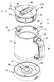
図1〜5を参照して、本発明の実施形態に係る電気ケトル(以下、ケトルという)を説明する。ケトル10は、図1及び図3に示すように、上方が開口し底部に加熱手段としての加熱ヒータ17が配置され、所定量の水などの液体が収容されるケトル本体11と、このケトル本体11が載置され、ケトル本体11の加熱ヒータ17に給電する給電台63と、ケトル本体11の上部開口12を覆う着脱自在な蓋体28と、ケトル本体11の側壁部に使用者が把持可能な取っ手部23とを設けた構成となっている。
With reference to FIGS. 1-5, the electric kettle (henceforth a kettle) which concerns on embodiment of this invention is demonstrated. As shown in FIGS. 1 and 3, the
図1〜図3に示すように、ケトル本体11は、上部開口12及び下部開口13を有し、所定の直径で形成された筒状体のフレーム14と、このフレーム14の外周側壁15面に外方へ突出し、把持可能な例えば「コの字」型の取っ手部23とを備え、耐熱性を有する樹脂成型体で形成されている。取っ手部23と対向する上部開口12の一部には、外側に屈曲した注ぎ口20が形成されている。このケトル本体11は、上部開口12側には蓋体28が着脱自在に装着され、下部開口13側には中央が開口された底蓋16により閉塞されている。この底蓋16には加熱ヒータ17が本体側給電器18とともに装着され、加熱ヒータ17上には液体が収容される容器19が設置されている。この容器19は、蓋体28が装着されることにより、液密になるように形成されている。
As shown in FIGS. 1 to 3, the kettle
図3に示すように、ケトル本体11には、上部開口12近傍の内壁にあって、取っ手部23が形成されている部分に取っ手部23に内蔵された蒸気センサ24に通じる蒸気導通孔21が形成されている。この取っ手部23は、ケトル本体11と一体に形成された取っ手部材27と、この取っ手部材27を覆う取っ手カバー25とで構成され、取っ手部23内は中空に形成されている。そして、この中空部内に、蒸気センサ24の検出値を入力して加熱ヒータ17を制御する不図示の制御手段が収納されており、蒸気センサ24と制御手段とは、図示しないリード線で接続されている。また、この取っ手部23には、取っ手カバー25の外側に加熱ヒータ17への通電をオン・オフする電源スイッチ26が配設されている。
As shown in FIG. 3, the kettle
取っ手部23に収容されている制御手段(図示省略)は、マイクロコンピュータ及びメモリなどを有し、メモリには、蒸気温度が所定値になったときに、加熱ヒータ17への通電を停止させる基準値(例えば85℃)が記憶されている。このように基準値を設定しておくことにより、制御手段は、検知された蒸気温度が基準値に達したときに、加熱ヒータ17への加熱を停止させる制御を行うので、液体を所望の温度(例えば沸騰温度)に加熱することができ、また、液体が沸騰し続けることを抑制することができる。
The control means (not shown) accommodated in the
図2に示すように、ケトル本体11が載置される給電台63は、中央に開口65を有し上面にケトル本体が設置される浅底の給電上台座64と、給電上台座64の下方を覆う不図示の給電下台座と、給電下台座に装着され、給電上台座64の中央の開口65から突出する給電器スタンド67と、電気コネクタとで構成されている。給電上台座64は、ケトル本体11の直径と略同じ直径の略円形状に形成された底部と、この底部の周囲から立設した背低の側壁部とを有し上方が開口した浅底の容器からなり、樹脂成型体で形成されている。電気コネクタは給電台63の略中心部に固定されている。この電気コネクタには、リード線が接続されて、このリード線の先端にプラグコネクタが接続されている。そして、給電台63の給電器スタンド67とケトル本体11の本体側給電器18とが電気的に接続され、通電されることで、ケトル本体11の加熱ヒータ17を加熱することができる。
As shown in FIG. 2, a
図2及び図4を参照して、蓋体28の構造について説明する。蓋体28は、中板29と、この中板29の周囲の上下方向にそれぞれ延在された所定高さを有する外周壁30と、外周壁30の上方に装着される上蓋31と、外周壁30の下方に装着される複数個の孔が形成された内蓋32とで形成されている。外周壁30には、ケトル本体11の容器19内の液体を注ぎ口20へと注水するための注水口33と、この注水口33の反対側に、ケトル本体11内で発生した蒸気を取っ手部23内の蒸気センサ24に導くための蒸気口36が形成されており、蒸気口36の周囲には蒸気パッキン34が装着されている。上蓋31には、開閉機構53のスイッチ54、着脱機構48の一対のつまみ部材37a、37b、及びケトル本体11に形成された注ぎ口20を覆う注口蓋38が形成されている。また、中板29と上蓋31との間には着脱機構48が収容される空間が形成されている。
With reference to FIG.2 and FIG.4, the structure of the
蓋体28の着脱機構48は、蓋体28の略中央に設けられている。着脱機構48は、蓋体28の上面に設けられた左右一対のつまみ部材37a、37b間に働かせたばね(図示省略)によって各つまみ部材37a、37bのそれぞれの係止片51a、51bが蓋体28の外周壁30に設けられた左右一対の開孔52a、52bから常時突出するようにしてある。これに対応するように、ケトル本体11の肩部に形成される左右一対の係合溝22a、22bに蓋体28の係止片51a、51bが係合するように形成されている。
The attaching /
中板29と外周壁30との間には、ケトル本体11の容器19内の液体を注水口33へと導く液体供給路49が形成されている。液体供給路49の開閉機構53は、着脱機構48と注水口33との間に形成されている。開閉機構53のスイッチ54を注ぎ口20側にスライドさせると、スイッチ54に連動した押圧部55が、中板29の液体供給口56を閉塞している開閉弁57を押すことで液体供給口56が開かれ、容器19内の液体が注水可能な状態となる。なお、このとき、開閉弁57と内蓋32との間に配置された開閉ばね58が押されて弾性変形することとなる。一方、この開状態のときスイッチ54を取っ手部側へスライドさせると、押圧部55の開閉弁57への押圧がなくなり、開閉弁57と内蓋32の間に配置された開閉ばね58の弾性力により、中板29の液体供給口56が開閉弁57により閉じられることとなる。
Between the
また、中板29と外周壁30との間には、容器19内で発生した蒸気の通り道となる蒸気弁室39が形成され、この蒸気弁室39と中板29との間には、蒸気センサ24及び液体供給路49の開閉弁57の下流側に連通する蒸気通路40が形成されている。図4A及び図4Bの矢印で示されるように、容器19の内部で液体が沸騰すると、発生した蒸気は蒸気弁室39を通過して蒸気導通口45から蒸気通路40に流入し、一部の蒸気は、液体供給路49の開閉弁57の下流側を通り、注水口33から注ぎ口20を通じて外部に排出される。このように、蒸気が、蒸気通路40を通って液体供給路49の開閉弁57の下流側に導かれ、蓋体28の上部ではなく注水口33を通じてケトル本体11の注ぎ口20から外部に排出されるため、本発明の実施形態に係る電気ケトルによれば、使用者が誤って蒸気にふれるおそれが少なくなり、安全性を高めることができる。また、開閉弁57が設けられているため、開閉弁57が閉じた状態でケトルが転倒等しても内部の液体が漏れる ことを抑制することができる。
Further, a
尚、本実施例装置では、容器19の内部で液体が沸騰すると、おもり44がその沸騰圧力により持ち上がり、蒸気が蒸気開口50から蒸気導通口45を通り蒸気通路40へと入るようになっているが、載置部46のすり鉢状の表面に複数の孔(図示せず)を形成し、容器19の内部で液体が沸騰すると、この複数の孔から蒸気が放出される構成としても良い。
In this embodiment, when the liquid boils inside the
蒸気の一部は蒸気通路40を導通した後、蒸気口36、蒸気導通孔21を通じて取っ手部23内の蒸気センサ24に接触する。このように、蒸気通路がケトル内の沸騰状態を判断する蒸気センサ24にも蒸気を導くように形成されていることから、蒸気を液体供給路及び蒸気センサに導くための蒸気通路を一体に形成することができ、ケトル内の液体が沸騰したことを検出するための構造を簡単にすることができる。
A part of the steam passes through the
また、本実施形態の電気ケトルにおいては、蒸気導通口45が取っ手部23と近接した位置に形成されているので、取っ手部23内に設けられた蒸気センサ24に近い位置の蒸気を蒸気センサ24によって検知させることができ、ケトル本体11内の沸騰の状態を正確に得ることができる。また、蒸気通路40内を通過する距離が短いため、蒸気温度が下がりにくく、より正確な蒸気温度を得ることもできる。
Further, in the electric kettle of the present embodiment, since the
さらに、蒸気通路40内には結露した液体を溜めておく液溜め部41が形成され、この液溜め部41には、溜まった液体を容器19内に戻す負圧弁42が形成されている。この負圧弁42は、液体を注ぐときに容器内が負圧になることで開放され、蒸気通路に蒸気が冷えたり、注水しきれず蒸気通路まで戻ってきたりして液溜め部41に溜まった液体をケトル本体11の容器19内に戻すことができるため、不要な液漏れを抑制することができる。
Further, a
また、蒸気弁室39には液漏れ抑制機構43が設けられている。この液漏れ抑制機構43は、ケトル本体11が転倒等したときに蒸気通路40を閉じるように構成されている。この蒸気弁室39は、蒸気弁室39内に収容された閉塞部材となるおもり44と、蒸気弁室39の出口部分におもり44の上面よりやや小さめの蒸気導通口45により形成されている。液漏れ抑制機構43は、おもり44の載置される表面がすり鉢状とされた載置部46と、底部を載置部46のすり鉢状の表面に嵌り合うように形成されたおもり44と、載置部46との隙間に形成される隙間通路47と、蒸気弁室39の底面部に設けられ、隙間通路と連通する蒸気開口50とで構成されている。
The
このように形成することで、液漏れ抑制機構43は、ケトル本体11が転倒等して傾いたとき、おもり44が載置部46の表面のすり鉢状の傾斜に沿って移動して蒸気導通口45を閉じ、液体が蒸気通路40を通じて注ぎ口20から外部に流出するのを抑制することができる。
By forming in this way, when the
10…ケトル
11…ケトル本体
14…フレーム
15…外周側壁
16…底蓋
17…加熱ヒータ
18…本体側給電器
19…容器
20…注ぎ口
21…蒸気導通孔
22a、22b…係合溝
23…取っ手部
28…蓋体
29…中板
30…外周壁
31…上蓋
32…内蓋
33…注水口
36…蒸気口
39…蒸気弁室
40…蒸気通路
42…負圧弁
43…液漏れ抑制機構
45…蒸気導通口
48…着脱機構
49…液体供給路
53…開閉機構
57…開閉弁
63…給電台
DESCRIPTION OF
Claims (5)
前記ケトル本体に収容された前記液体を加熱する加熱手段と、
前記ケトル本体の前記開口を覆う着脱自在な蓋体と、
を有する電気ケトルにおいて、
前記蓋体は、
前記ケトル本体に収容された前記液体を前記ケトル本体の前記注ぎ口と対応する位置に形成された注水口を経て供給するための液体供給路と、
前記液体供給路と前記ケトル本体との間に形成された、前記液体を前記液体供給路に導くための液体供給口と、
前記液体供給口の開け閉めを行う開閉弁と、
前記ケトル本体内で発生した蒸気を導通させる蒸気通路と、
前記蒸気通路と前記ケトル本体との間に形成された、蒸気を蒸気通路に導くための蒸気導通口と、を有し、
前記蒸気通路は前記液体供給路の前記開閉弁の下流側と連通され、
前記蒸気通路を導通された蒸気は、前記液体供給路を通って、前記注水口から外部に排出されることを特徴とする電気ケトル。 A kettle body having an opening above and a spout bent outwardly in a part of the opening is formed, and a predetermined amount of liquid is accommodated therein,
Heating means for heating the liquid contained in the kettle body;
A detachable lid that covers the opening of the kettle body;
In an electric kettle having
The lid is
A liquid supply path for supplying the liquid contained in the kettle body through a water inlet formed at a position corresponding to the pouring hole of the kettle body;
A liquid supply port formed between the liquid supply path and the kettle body for guiding the liquid to the liquid supply path;
An on-off valve for opening and closing the liquid supply port;
A steam passage for conducting steam generated in the kettle body;
A steam conduction port formed between the steam passage and the kettle body for guiding the steam to the steam passage;
The vapor passage communicates with the downstream side of the on-off valve of the liquid supply passage,
The electric kettle characterized in that the vapor conducted through the vapor passage is discharged to the outside from the water injection port through the liquid supply path.
前記蓋体が装着される側の前記取っ手部の内部には蒸気センサーが設けられ、
前記蓋体には前記蒸気センサーと対向する位置に蒸気口が形成され、
前記蒸気通路は、前記ケトル本体の前記開孔及び前記蓋体の前記蒸気口と連通され、前記蒸気を前記蒸気センサーにも導通させるように形成されていることを特徴とする請求項1に記載のケトル。 The kettle body is formed with a handle on the side facing the pouring spout, and an opening communicating with the handle is formed on the side of the handle where the lid is attached,
A steam sensor is provided inside the handle on the side where the lid is mounted,
In the lid body, a steam port is formed at a position facing the steam sensor,
2. The steam passage according to claim 1, wherein the steam passage communicates with the opening of the kettle main body and the steam port of the lid body, and is formed so as to conduct the steam to the steam sensor. Kettle.
前記蒸気弁室の上面部には前記蒸気導通口が形成され、
前記蒸気弁室の内部には前記蒸気導通口を閉塞可能な大きさの閉塞部材が載置され、
前記蒸気弁室と前記閉塞部材との間には蒸気が通過可能な隙間通路が形成され、
前記蒸気弁室の底面部には前記隙間通路と連通する蒸気開口が形成され、
前記液漏れ抑制機構は、前記ケトル本体が傾いたとき、前記蒸気導通口が前記閉塞部材によって閉塞されることを特徴とする請求項1〜3のいずれかに記載のケトル。 A hollow box-shaped steam valve chamber having a liquid leakage suppression mechanism is provided between the steam passage and the steam conduction port,
The steam conduction port is formed in the upper surface portion of the steam valve chamber,
A blocking member having a size capable of closing the steam conduction port is placed inside the steam valve chamber,
A gap passage through which steam can pass is formed between the steam valve chamber and the closing member,
A steam opening communicating with the gap passage is formed in the bottom portion of the steam valve chamber,
4. The kettle according to claim 1, wherein when the kettle main body is tilted, the liquid leakage suppressing mechanism is configured such that the steam conduction port is closed by the closing member.
Priority Applications (1)
| Application Number | Priority Date | Filing Date | Title |
|---|---|---|---|
| JP2011036841A JP2012170706A (en) | 2011-02-23 | 2011-02-23 | Electric kettle |
Applications Claiming Priority (1)
| Application Number | Priority Date | Filing Date | Title |
|---|---|---|---|
| JP2011036841A JP2012170706A (en) | 2011-02-23 | 2011-02-23 | Electric kettle |
Publications (1)
| Publication Number | Publication Date |
|---|---|
| JP2012170706A true JP2012170706A (en) | 2012-09-10 |
Family
ID=46974153
Family Applications (1)
| Application Number | Title | Priority Date | Filing Date |
|---|---|---|---|
| JP2011036841A Withdrawn JP2012170706A (en) | 2011-02-23 | 2011-02-23 | Electric kettle |
Country Status (1)
| Country | Link |
|---|---|
| JP (1) | JP2012170706A (en) |
Cited By (7)
| Publication number | Priority date | Publication date | Assignee | Title |
|---|---|---|---|---|
| JP2013141565A (en) * | 2012-01-12 | 2013-07-22 | Tiger Vacuum Bottle Co Ltd | Electric kettle |
| KR101454796B1 (en) * | 2013-05-29 | 2014-11-03 | (주) 대동에프앤디 | Sepetated pressure cooker from base housing |
| JP2014217558A (en) * | 2013-05-08 | 2014-11-20 | 象印マホービン株式会社 | Water heater |
| CN104257285A (en) * | 2014-10-21 | 2015-01-07 | 广东美的生活电器制造有限公司 | Electric kettle and kettle cover thereof |
| JP2018020288A (en) * | 2016-08-04 | 2018-02-08 | 株式会社 東亜産業 | Electric kettle with hydrogen generation function |
| CN112021930A (en) * | 2019-06-03 | 2020-12-04 | 中山市心好电器有限公司 | Water inlet funnel with good mosquito prevention effect for electric kettle |
| CN113040603A (en) * | 2021-03-12 | 2021-06-29 | 四川虹美智能科技有限公司 | Liquid heating device |
-
2011
- 2011-02-23 JP JP2011036841A patent/JP2012170706A/en not_active Withdrawn
Cited By (7)
| Publication number | Priority date | Publication date | Assignee | Title |
|---|---|---|---|---|
| JP2013141565A (en) * | 2012-01-12 | 2013-07-22 | Tiger Vacuum Bottle Co Ltd | Electric kettle |
| JP2014217558A (en) * | 2013-05-08 | 2014-11-20 | 象印マホービン株式会社 | Water heater |
| KR101454796B1 (en) * | 2013-05-29 | 2014-11-03 | (주) 대동에프앤디 | Sepetated pressure cooker from base housing |
| CN104257285A (en) * | 2014-10-21 | 2015-01-07 | 广东美的生活电器制造有限公司 | Electric kettle and kettle cover thereof |
| JP2018020288A (en) * | 2016-08-04 | 2018-02-08 | 株式会社 東亜産業 | Electric kettle with hydrogen generation function |
| CN112021930A (en) * | 2019-06-03 | 2020-12-04 | 中山市心好电器有限公司 | Water inlet funnel with good mosquito prevention effect for electric kettle |
| CN113040603A (en) * | 2021-03-12 | 2021-06-29 | 四川虹美智能科技有限公司 | Liquid heating device |
Similar Documents
| Publication | Publication Date | Title |
|---|---|---|
| JP2012170706A (en) | Electric kettle | |
| JP2012170707A (en) | Electric kettle | |
| JP2012081245A (en) | Electric kettle | |
| JP2011072722A (en) | Electric kettle | |
| JP5936053B2 (en) | Liquid heating container | |
| JP5936052B2 (en) | Liquid heating container | |
| JP6103101B2 (en) | Liquid heating container | |
| JP2016137286A (en) | Liquid heating vessel | |
| JP6372584B2 (en) | Liquid heating container | |
| CN213464719U (en) | Cooking device | |
| JP2016152986A (en) | Liquid heating container | |
| JP5321273B2 (en) | Electric kettle | |
| JP2012239710A (en) | Electric kettle | |
| JP5928174B2 (en) | Liquid heating container | |
| RU2730269C2 (en) | Steam boiler | |
| JP2016005609A (en) | Electric kettle | |
| JP7161106B2 (en) | electric kettle | |
| JP7189436B2 (en) | Double-walled container with water level indicator window | |
| JP7227489B2 (en) | Seal structure for electrical equipment | |
| JP2016152987A (en) | Liquid heating container | |
| JP7121265B2 (en) | kettle | |
| JPH05344930A (en) | Electric pot | |
| JP7303427B2 (en) | Steam detection mechanism for electrical equipment | |
| JP2013126591A (en) | Electric kettle | |
| JP2012192281A (en) | Electric kettle |
Legal Events
| Date | Code | Title | Description |
|---|---|---|---|
| RD01 | Notification of change of attorney |
Free format text: JAPANESE INTERMEDIATE CODE: A7421 Effective date: 20130628 |
|
| A300 | Withdrawal of application because of no request for examination |
Free format text: JAPANESE INTERMEDIATE CODE: A300 Effective date: 20140513 |