JP2012167659A - Compressor and refrigeration cycle device - Google Patents
Compressor and refrigeration cycle device Download PDFInfo
- Publication number
- JP2012167659A JP2012167659A JP2011031628A JP2011031628A JP2012167659A JP 2012167659 A JP2012167659 A JP 2012167659A JP 2011031628 A JP2011031628 A JP 2011031628A JP 2011031628 A JP2011031628 A JP 2011031628A JP 2012167659 A JP2012167659 A JP 2012167659A
- Authority
- JP
- Japan
- Prior art keywords
- blade
- cylinder chamber
- cylinder
- blade groove
- compressor
- Prior art date
- Legal status (The legal status is an assumption and is not a legal conclusion. Google has not performed a legal analysis and makes no representation as to the accuracy of the status listed.)
- Withdrawn
Links
Images
Landscapes
- Applications Or Details Of Rotary Compressors (AREA)
Abstract
【課題】ブレード溝の深さがシリンダ室の深さよりも深いと、圧縮機の運転時にブレードが摺動運動すると、シリンダ室底面とブレード溝底面の段差によってブレードの摺動運動が妨げられ、性能の低下やブレード先端の欠けによる圧縮機の故障の原因となる恐れがある。
【解決手段】圧縮機は、回転軸と、軸受部とシリンダ室4とシリンダ室に連通するブレード溝11とが形成された一体型シリンダを有している。シリンダ室内には偏心回転可能にローラが配されており、ブレード溝内にはシリンダ室内を二分するブレードが配されている。シリンダ室は閉塞部材により閉塞されている。そして、この一体型シリンダは、シリンダ室の深さ寸法よりも、ブレード溝の深さ寸法が小さく形成されている。
【選択図】図5When the blade groove depth is deeper than the cylinder chamber depth, when the blade slides during operation of the compressor, the blade sliding motion is hindered by the step between the cylinder chamber bottom surface and the blade groove bottom surface. There is a risk of causing a compressor failure due to lowering of the blade or chipping of the blade tip.
The compressor has an integral cylinder in which a rotating shaft, a bearing portion, a cylinder chamber 4 and a blade groove 11 communicating with the cylinder chamber are formed. A roller is arranged in the cylinder chamber so as to be eccentrically rotatable, and a blade that bisects the cylinder chamber is arranged in the blade groove. The cylinder chamber is closed by a closing member. The integrated cylinder is formed so that the depth dimension of the blade groove is smaller than the depth dimension of the cylinder chamber.
[Selection] Figure 5
Description
本発明の実施の形態は、圧縮機及びこの圧縮機を備えた冷凍サイクル装置に関する。 Embodiments described herein relate generally to a compressor and a refrigeration cycle apparatus including the compressor.
一般的な圧縮機として、圧縮機構部のシリンダ室内を、ローラが偏心回転することで、流体を圧縮するロータリ型の圧縮機が知られている。このような圧縮機の圧縮機構部は、内周面に囲まれたシリンダ室を有するシリンダ部と、回転軸を支持するとともに、シリンダ室を閉塞する閉塞部材と、ローラの外周面に当接しシリンダ室内を吸込み側と吐出側とに二分するブレードを有している。
更に、上記圧縮機には、シリンダ部と軸受部とが一体に形成された圧縮機構部を備えたものがある。
As a general compressor, there is known a rotary type compressor that compresses a fluid by rotating a roller eccentrically in a cylinder chamber of a compression mechanism section. The compression mechanism portion of such a compressor has a cylinder portion having a cylinder chamber surrounded by an inner peripheral surface, a closing member that supports the rotation shaft and closes the cylinder chamber, and an outer peripheral surface of the roller in contact with the cylinder. It has a blade that divides the room into a suction side and a discharge side.
Further, some of the compressors include a compression mechanism portion in which a cylinder portion and a bearing portion are integrally formed.
シリンダ部と軸受部とが一体に形成された一体型シリンダは、シリンダ室とブレードを配置するために設けられるブレード溝が、切削加工により、必要な寸法と表面性状に加工形成される。 In the integrated cylinder in which the cylinder portion and the bearing portion are integrally formed, a blade groove provided for disposing the cylinder chamber and the blade is processed and formed into necessary dimensions and surface properties by cutting.
ここで、シリンダ部と軸受部とが一体に形成された一体型シリンダは、シリンダ室とブレード溝が、別工程で加工される。シリンダ部と軸受部が別体に形成される場合、シリンダ室の底面とブレード溝の底面は、軸受部の端面であるため、同一平面上となる。しかし、別工程により加工される場合、シリンダ室の底面とブレード溝の底面とに段差を生じ同一平面上とならない。特に、ブレード溝の深さがシリンダ室の深さよりも深いと、圧縮機の運転時にブレードが摺動運動すると、シリンダ室底面とブレード溝底面の段差によってブレードの摺動運動が妨げられ、性能の低下やブレード先端の欠けによる圧縮機の故障の原因となる恐れがある。
本発明の実施形態は、シリンダ室底面とブレード溝の底面との段差によって、ブレードの摺動運動が妨げられず、信頼性の高い圧縮機を提供する。
Here, in the integrated cylinder in which the cylinder portion and the bearing portion are integrally formed, the cylinder chamber and the blade groove are processed in separate steps. When the cylinder portion and the bearing portion are formed separately, the bottom surface of the cylinder chamber and the bottom surface of the blade groove are on the same plane because they are end surfaces of the bearing portion. However, when processing is performed in a separate process, a step is generated between the bottom surface of the cylinder chamber and the bottom surface of the blade groove and is not flush with each other. In particular, if the depth of the blade groove is deeper than the depth of the cylinder chamber, when the blade slides during the operation of the compressor, the sliding movement of the blade is hindered by the step between the cylinder chamber bottom surface and the blade groove bottom surface. It may cause a compressor failure due to a drop or chipping of the blade tip.
The embodiment of the present invention provides a highly reliable compressor in which the sliding movement of the blade is not hindered by the step between the bottom surface of the cylinder chamber and the bottom surface of the blade groove.
本発明の実施形態の圧縮機は、回転軸と、軸受部とシリンダ室とシリンダ室に連通するブレード溝とが形成された一体型シリンダを有している。シリンダ室内には偏心回転可能にローラが配されており、ブレード溝内にはシリンダ室内を二分するブレードが配されている。シリンダ室は閉塞部材により閉塞されている。
そして、この一体型シリンダは、シリンダ室の深さ寸法よりも、ブレード溝の深さ寸法が小さく形成されている。
The compressor of the embodiment of the present invention has an integral cylinder in which a rotating shaft, a bearing portion, a cylinder chamber, and a blade groove communicating with the cylinder chamber are formed. A roller is arranged in the cylinder chamber so as to be eccentrically rotatable, and a blade that bisects the cylinder chamber is arranged in the blade groove. The cylinder chamber is closed by a closing member.
The integrated cylinder is formed so that the depth dimension of the blade groove is smaller than the depth dimension of the cylinder chamber.
以下、本発明の実施形態を図面に基づいて説明する。
(第1の実施形態)
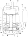
図1に本実施形態の圧縮機100の縦断面図を示す。
第1の実施形態の圧縮機100は冷媒を圧縮する密閉型のロータリ圧縮機であり、縦長円筒状の密閉ケース1の内部に、下方に配置された圧縮機構部2と上方に配置された電動機部3を備えている。圧縮機構部2と電動機部3は、回転軸9によって連結されており、電動機部3で発生した回転動力は回転軸9を介して圧縮機構部2に伝達される。
Hereinafter, embodiments of the present invention will be described with reference to the drawings.
(First embodiment)
FIG. 1 shows a longitudinal sectional view of a
The
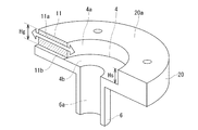
圧縮機構部2は、一体型シリンダ20を有している。一体型シリンダ20は、一端側に回転軸9を支持する軸受部である主軸受部6が形成されている。
一体型シリンダ20の他端側には、略円柱状の空洞部であるシリンダ室4と、シリンダ室4に連通したブレード溝11が設けられている。シリンダ室4内には回転軸9の中途部に設けられた軸偏心部8と、軸偏心部8に嵌合されるローラ10が偏心回転可能に配されている。また、ブレード溝11内には略矩形状のブレード12が往復移動自在に配されている。
The
On the other end side of the integrated
また、ローラ10は、シリンダ室4の内周面4aに対面し凹凸がなく滑らかに形成された外周面10aを有し、略円筒形状に形成されている。
ブレード12は基端がバネ30により押圧され、先端面12aがローラ10の外周面10aに当接されたまま、ローラ10の偏心回転に伴ってブレード溝11内を往復移動する。これにより、シリンダ室4内を低圧の吸込側と高圧の吐出側とに二分している。
The
The base end of the
そして、一体型シリンダ20の他端には、閉塞部材であり、回転軸9の支持部材でもある副軸受7が設けられており、シリンダ室4とブレード溝11を閉塞している。
The other end of the integrated
シリンダ室4の吸込み側には、密閉ケース1外部から冷媒を吸込むための図示しない吸込み口が設けられており、この吸込み口は密閉ケース1外部の気液分離器40に連通している。そして、主軸受部6には図示しない吐出通路が設けられており、この吐出通路は吐出方向にのみ開閉可能な吐出弁14によって閉塞されている。さらに、主軸受部6の上部には吐出マフラ15が設けられており、吐出通路を覆っている。
また、密閉ケース1内の下方には潤滑油31が貯留されており、圧縮機構部2内のシリンダ室4や主軸受部6及び副軸受7の摺動面に供給されるようになっている。
A suction port (not shown) for sucking refrigerant from the outside of the sealed
A lubricating
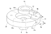
図2に、一体型シリンダ20に形成されたブレード溝11の深さ寸法Hg及び幅寸法Wgと、ブレード12の高さ寸法Hb及び幅寸法Wbを示す。なお、図2の一体型シリンダ20は図1と上下方向が逆転した状態で表示されている。
ブレード12の高さ寸法Hbは、一体型シリンダ20に設けられたブレード溝11の深さ寸法Hgと略同一に形成されており、ブレード12の幅寸法Wbは、ブレード溝11の幅寸法Wgと略同一に形成されている。ただし、ブレード12の高さ寸法Hbと幅寸法Wbは、ブレード溝11内を摺動運動するためブレード溝11の深さ寸法Hg及び幅寸法Wgよりも、数μm程度小さく形成されており、潤滑油31が流入する程度の間隙が設けられるようになっている。
一体型シリンダ20は、複合旋盤等の加工機に位置決め固定され、以下の一連の工程により、切削及び研磨され、軸受部6の内径面6aと、シリンダ室4の内周面4a及び一端側の底面4bと、ブレード溝11の側面11a及び一端側底面11bが必要な表面性状と寸法精度に加工形成される。
FIG. 2 shows the depth dimension Hg and width dimension Wg of the
The height dimension Hb of the
The integrated
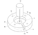
図3に、一体型シリンダ20を回転させ、切削工具50により旋削加工を行う様子を示す。この旋削加工は、図3中の破線矢印で示す方向に被削材である一体型シリンダ20を回転させつつ、実線矢印方向へ切削工具50を送りながら切削を行うもので、第1ないし第4工程で行う。
まず、第1工程として、被削材である一体型シリンダ20を回転させながらシリンダ室4の内周面4aが切削加工され、必要な表面性状と寸法精度に形成される。
次に、第2工程として、主軸受部6の内径面6aが切削加工され、必要な表面性状と寸法精度に形成される。
次に、第3工程として、シリンダ室4の底面4bが切削加工され必要な表面性状と寸法精度に形成される。その後、第4工程として一体型シリンダ20の他端面20aを旋削されることにより、必要な表面性状と寸法精度に形成される。
このときの、一体型シリンダ20の他端面20aからシリンダ室4の底面4bまでの深さ寸法を計測し、この深さ寸法をHsとする。
FIG. 3 shows a state in which the integrated
First, as the first step, the inner
Next, as a second step, the
Next, as a third step, the
At this time, the depth dimension from the
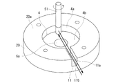
次に、図4に示すエンドミル加工による、第5工程の加工を行う。一体型シリンダ20の回転を停止させ、エンドミル工具51を図4の破線矢印の方向へ回転させ、実線矢印の方向へ工具送りを行う。そして、エンドミル工具51の側面と先端面をブレード溝11の底面11bと側面11aへ当接相対運動させ切削を行う。
エンドミル工具51の軸方向は一体型シリンダ20の軸方向に対して平行になっている。ブレード溝11の側面11aはエンドミル工具51の側面で切削され、ブレード溝11の底面11bはエンドミル工具51の先端面で切削される。
ここで、図5に示すように、ブレード溝11の深さ寸法Hgは、第4工程において計測されたシリンダ室4の深さ寸法Hsよりも数μmから十数μm程度小さくなるように切削される。
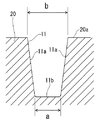
ここで、ブレード溝11の底面11bと側面11aとの境には、エンドミル工具51の先端形状が転写されるため、数μmから数十μmの曲率半径を有する凹曲面(図6参照)が形成される。そのため、ブレード溝11に配されるブレード12の、ブレード溝11の凹曲面に対向する角部には、凹曲面と略同一の曲率半径を有する凸曲面が形成されるのが好ましい。
Next, the 5th process is performed by the end mill process shown in FIG. The rotation of the integrated
The axial direction of the
Here, as shown in FIG. 5, the depth dimension Hg of the
Here, since the tip shape of the
ブレード溝11を切削するエンドミル工具の刃直径はブレード溝11よりも細くなければならないが、細すぎると切削時に工具のたわみ量が大きくなるため、ブレード溝11の幅寸法Wgに最も近い刃直径を有するエンドミル工具を使用するのが好ましい。
The blade diameter of the end mill tool that cuts the
図6に示すように、ブレード溝11の両側面11a、11a間の寸法は、エンドミル工具のたわみ変形の影響から、主軸受側の底部幅aよりも他端側の開口部幅bの方が数μmから数十μm程度大きく形成される。この底部幅aと開口部幅bの差はブレード溝11の幅寸法Wgと深さ寸法Hgの比(Hg/Wg)に応じて変化する。即ち、ブレード溝11の深さ寸法Hgが深く幅寸法Wgが狭いと、エンドミル工具51は必然的に細長いものを使用する必要があり、エンドミル工具51のたわみ量が大きくなる。これにより、ブレード溝11の側面11aが傾斜し、底部幅aよりも開口部幅bが大きくなる。
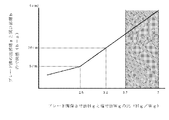
ブレード溝11の深さ寸法Hgと幅寸法Wgの比(Hg/Wg)と、ブレード溝11の底部幅aと開口部幅bの寸法差(b−a)の計測から求められた関係を図7に示す。
従来のシリンダと主軸受が別体に構成された圧縮機構部を有する圧縮機は、一般的にブレード溝の深さ寸法Hgと幅寸法Wgの比(Hg/Wg)が3.7〜7の範囲にある。
As shown in FIG. 6, the dimension between the side surfaces 11a and 11a of the
FIG. 6 shows the relationship obtained from the measurement of the ratio of the depth dimension Hg and the width dimension Wg (Hg / Wg) of the
In a compressor having a compression mechanism portion in which a conventional cylinder and a main bearing are configured separately, the ratio of the depth dimension Hg of the blade groove to the width dimension Wg (Hg / Wg) is generally 3.7-7. Is in range.
ブレード溝11の底部幅aと開口部幅bとの差が大きいと、ブレード溝11とブレード12との間隙が不均一となり、運転時のブレード12のズレが生じ、圧縮機100の信頼性低下の原因となる。また、開口部幅bが大きくなると、ブレード溝11とブレード12の間隙が大きくなり、圧縮機構部2の気密性が確保されなくなる。特に、底部幅aと開口部幅bの寸法差(b−a)が10μmを越えた場合、ブレード溝11とブレード12の間に設けられた間隙が潤滑油31による気密性を保持できなくなり、圧縮機100の性能が著しく低下する。
これに対して、ブレード溝の深さ寸法Hgと幅寸法Wgの比(Hg/Wg)を3.2以下とすると、エンドミル工具51のたわみが低減され、底部幅aと開口部幅bの寸法差(b−a)が10μm未満となり、ブレード溝11とブレード12間の気密性を高くすることができ、圧縮機100の著しい性能低下を抑えることができる。
If the difference between the bottom width a of the
On the other hand, when the ratio (Hg / Wg) of the depth dimension Hg and the width dimension Wg of the blade groove is 3.2 or less, the deflection of the
シリンダ室4の内周直径と深さ寸法Hsは、必要とされる圧縮機構部2の排除容積によって決定される値であり、このシリンダ室4の深さ寸法Hsによりブレード溝11の深さ寸法Hg及びブレード12の高さ寸法Hbが決定される。
ここで、ブレード12とブレード溝11間の間隙は気密性保持のため10μm以下であることが好ましい。
The inner peripheral diameter and depth dimension Hs of the
Here, the gap between the
ローラ10の外周面10aとシリンダ室4の内周面4aの間隙と、ローラ10の一端側の端面とシリンダ室4の底面4aとの間隙は、潤滑油31による油膜で満たされており、ローラ10の摺動回転が良好で、シリンダ室4内の気密性が保持されている。
The gap between the outer
更に、ローラ10の外周面10aには、ブレード12に常時当接する溝がなく、回転軸9が回転し、軸偏心部8とローラ10とが偏心回転すると、ローラ10は軸偏心部8の周囲で滑らかに自転するようになっている。これにより、ローラ10の外周面10aが局部的にブレード12の先端面12aに当接することがなく、外周面10aの一部分が摩耗し、摩耗粉が圧縮機構部2内へ飛散することがない。
Further, the outer
上記のように構成された圧縮機100の運転を以下に説明する。
圧縮機100外部から駆動電流が供給され、電動機部3が駆動すると、回転軸9が回転し、圧縮機構部2のシリンダ部5のシリンダ室4内で、軸偏心部8及びローラ10が偏心回転する。そして、圧縮機100の吸込口から吸込まれた低温低圧の冷媒が圧縮機構部2のシリンダ室4の吸込み側へ吸込まれる。シリンダ室4内へ吸込まれた冷媒は、ローラ10の偏心回転により圧縮されて高温高圧の冷媒となり、シリンダ室4の吐出側から吐出通路13と吐出マフラを介して密閉ケース1内へ吐出され、密閉ケース1の上部に設けられた吐出管32から密閉ケース1外部へ吐出される。
The operation of the
When a drive current is supplied from the outside of the
本実施形態のように、旋削加工によりシリンダ室4の底面を切削した後、シリンダ室4の深さ寸法Hsを計測し、ブレード溝11の深さ寸法Hgよりもシリンダ室4の深さ寸法Hsを深く形成することにより、ブレード12がシリンダ室4とブレード溝11との加工工程の差異によって形成される段差に当たることなく、滑らかに往復運動させる形状とすることができる。
これにより、摺動損失が小さく、ブレード12と一体型シリンダ20が摩耗することなく、信頼性の高い圧縮機100を提供することができる。
As in this embodiment, after the bottom surface of the
Thereby, the sliding loss is small, and the highly
Hg/Wg<3.2とすると、エンドミル工具51のたわみが低減され、底部幅aと開口部幅bの寸法差(b−a)が10μm未満となり、ブレード溝11とブレード12間の気密性を高くすることができ、性能の高い圧縮機100を提供することができる。
If Hg / Wg <3.2, the deflection of the
また、ローラ10の外周面10aに凹部を設けず滑らかに自転可能とすることで、ローラ10の外周面10aとブレード12の先端面12aの当接面が常に変化し、ローラ10の外周面10aが摩耗しない、更に頼性の高い圧縮機100を提供することができる。
(第2の実施形態)
Further, by allowing the outer
(Second Embodiment)
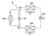
上記第1の実施形態の圧縮機100は、例えば空気調和機やヒートポンプ給湯機等の冷凍サイクル装置Aに設けられる。第2の実施形態は圧縮機100を用いた冷凍サイクル装置Aに関するもので、冷凍サイクル装置Aの概略を図8に示し説明する。
冷凍サイクル装置Aは、圧縮機100に接続された四方弁101と、第1熱交換器102と、膨張装置103と、第2熱交換器104とを備えており、順次冷媒配管で接続されている。この冷凍サイクル装置100内には作動流体である冷媒が封入されている。
The
The refrigeration cycle apparatus A includes a four-
圧縮機100で圧縮され吐出された冷媒は、四方弁101を介して実線矢印で示すように第1熱交換器102に供給される。このとき、第1熱交換器102は凝縮器として機能し、冷媒から凝縮熱を奪いつつ凝縮させる。
第1熱交換器102で凝縮された作動冷媒は、冷媒配管を介して膨張装置103で減圧されつつ第2熱交換器104に流動される。第2熱交換器104は蒸発器として機能し、冷媒から蒸発熱を奪いつつ蒸発させる。蒸発した作動冷媒は、冷媒配管と四方弁101を介して圧縮機100に吸い込まれ、冷媒は以上の経路を循環し、冷凍サイクル装置Aの運転は継続される。
The refrigerant compressed and discharged by the
The working refrigerant condensed in the
また、四方弁101により流路が切替えられることで、冷媒は図5の破線矢印で示される経路を循環する。即ち、圧縮機100から吐出された冷媒は、四方弁101から第2熱交換器104と、膨張装置103と、第1熱交換器102を順次流動し四方弁101を介して圧縮機100へ吸込まれる経路を循環する。このとき、第1熱交換器102は蒸発器として機能し、第2熱交換器104は凝縮器として機能する。
Further, the flow path is switched by the four-
上記のように、冷凍サイクル装置Aに、性能と信頼性の高い圧縮機100を用いることで、性能が高く信頼性の高い冷凍サイクル装置を提供することができる。
As described above, by using the
なお、上記第1乃至第3の実施形態は、圧縮機構部が1段の圧縮機について説明したが、圧縮機構部を複数用いても良い。例えば、2段の圧縮機構部を設けて、一体型シリンダのシリンダ室を閉塞する閉塞部材として、2段の圧縮機構部を仕切る仕切り板を用いても良い。
また、密閉ケース内に圧縮機構部と電動機部が設けられた密閉型の圧縮機について説明したが、開放型のケース内に圧縮機構部を設け、ケース外に電動機部やエンジン等の駆動要素を配置して用いても良い。
In the first to third embodiments, a compressor having a single-stage compression mechanism has been described. However, a plurality of compression mechanisms may be used. For example, a partition plate that partitions the two-stage compression mechanism portion may be used as a closing member that closes the cylinder chamber of the integrated cylinder by providing a two-stage compression mechanism portion.
In addition, although the closed type compressor in which the compression mechanism unit and the motor unit are provided in the sealed case has been described, the compression mechanism unit is provided in the open type case, and the driving elements such as the motor unit and the engine are provided outside the case. You may arrange and use.
また、この発明は、上記実施形態そのままに限定されるものではなく、実施段階ではその要旨を逸脱しない範囲で構成要素を変形して具体化できる。また、上記実施形態に開示されている複数の構成要素を適宜組み合わせることにより種々の発明を形成できる。全ての構成要素からいくつかの構成要素を削除してもよい。 Further, the present invention is not limited to the above-described embodiments as they are, and can be embodied by modifying the constituent elements without departing from the scope of the invention in the implementation stage. Further, various inventions can be formed by appropriately combining a plurality of constituent elements disclosed in the embodiment. Some components may be deleted from all the components.
1…密閉ケース、2…圧縮機構部、3…電動機部、4…シリンダ室、5…シリンダ部、6…主軸受部、7…副軸受、8…軸偏心部、9…回転軸、10…ローラ、10a…外周面、11…ブレード溝、12…ブレード、12a…先端面、14…吐出弁装置、20…一体型シリンダ、30…バネ、31…潤滑油、40…気液分離器、
100…圧縮機、101…四方弁、102…第1熱交換機、103…膨張装置、104…第2熱交換器、A…冷凍サイクル装置
DESCRIPTION OF
DESCRIPTION OF
Claims (3)
一端側に前記回転軸を支持する軸受部が形成されて、他端側に円柱状のシリンダ室と、前記シリンダ室に連通するブレード溝とが形成された一体型シリンダと、
前記一体型シリンダの他端側の端面に設けられ、前記シリンダ室を閉塞する閉塞部材と、
前記シリンダ室内に偏心回転可能に配置されたローラと、
前記ローラの外周面に常時当接する先端面を有し、前記シリンダ室内を二分し、前記ブレード溝内を往復移動可能に配されたブレードとを備え、
前記シリンダ室の深さ寸法よりも、前記ブレード溝の深さ寸法が、小さく形成されることを特徴とする圧縮機。 A rotation axis;
An integral cylinder in which a bearing portion supporting the rotating shaft is formed on one end side, a cylindrical cylinder chamber on the other end side, and a blade groove communicating with the cylinder chamber;
A closing member that is provided on an end surface of the other end of the integrated cylinder and closes the cylinder chamber;
A roller disposed eccentrically rotatable in the cylinder chamber;
A front end surface that is in constant contact with the outer peripheral surface of the roller, and bisects the cylinder chamber, and includes a blade disposed so as to be capable of reciprocating in the blade groove;
The compressor characterized in that the depth dimension of the blade groove is smaller than the depth dimension of the cylinder chamber.
Priority Applications (1)
| Application Number | Priority Date | Filing Date | Title |
|---|---|---|---|
| JP2011031628A JP2012167659A (en) | 2011-02-17 | 2011-02-17 | Compressor and refrigeration cycle device |
Applications Claiming Priority (1)
| Application Number | Priority Date | Filing Date | Title |
|---|---|---|---|
| JP2011031628A JP2012167659A (en) | 2011-02-17 | 2011-02-17 | Compressor and refrigeration cycle device |
Publications (1)
| Publication Number | Publication Date |
|---|---|
| JP2012167659A true JP2012167659A (en) | 2012-09-06 |
Family
ID=46972025
Family Applications (1)
| Application Number | Title | Priority Date | Filing Date |
|---|---|---|---|
| JP2011031628A Withdrawn JP2012167659A (en) | 2011-02-17 | 2011-02-17 | Compressor and refrigeration cycle device |
Country Status (1)
| Country | Link |
|---|---|
| JP (1) | JP2012167659A (en) |
-
2011
- 2011-02-17 JP JP2011031628A patent/JP2012167659A/en not_active Withdrawn
Similar Documents
| Publication | Publication Date | Title |
|---|---|---|
| US8635884B2 (en) | Multi-cylinder rotary compressor and refrigeration cycle apparatus | |
| JP2014034940A (en) | Rotary compressor and refrigeration cycle device | |
| JP4864572B2 (en) | Rotary compressor and refrigeration cycle apparatus using the same | |
| JP2007198319A (en) | Hermetic rotary compressor and refrigeration cycle apparatus | |
| JPWO2017061014A1 (en) | Rotary compressor | |
| JP2009062930A (en) | 2-cylinder rotary compressor and refrigeration cycle apparatus | |
| JP2013185523A (en) | Compressor and refrigerating cycle device | |
| JP5422658B2 (en) | Multi-cylinder rotary compressor and refrigeration cycle equipment | |
| JP2012154263A (en) | Compressor and refrigerating cycle system | |
| JP2012167659A (en) | Compressor and refrigeration cycle device | |
| JP6704555B1 (en) | Compressor and refrigeration cycle device | |
| JP5797450B2 (en) | Compressor manufacturing method. | |
| JP2009062929A (en) | Rotary compressor and refrigeration cycle apparatus | |
| JP5781355B2 (en) | Hermetic rotary compressor | |
| JP2009203862A (en) | Hermetic electric compressor and refrigerating cycle device | |
| EP3327289A1 (en) | Rotary compressor and refrigeration cycle device | |
| JP6758422B2 (en) | Rotating compressor | |
| JP5738030B2 (en) | Rotary compressor and refrigeration cycle apparatus | |
| JP2012225261A (en) | Rotary compressor | |
| JP5948209B2 (en) | Hermetic compressor and refrigeration cycle apparatus | |
| JP4910440B2 (en) | Compressor | |
| WO2023166554A1 (en) | Rotary compressor and refrigeration cycle device | |
| JP2017072070A (en) | Hermetic compressor | |
| JP2000009069A (en) | Rotary fluid machine | |
| JPH1182343A (en) | Rolling piston type rotary compressor |
Legal Events
| Date | Code | Title | Description |
|---|---|---|---|
| A300 | Withdrawal of application because of no request for examination |
Free format text: JAPANESE INTERMEDIATE CODE: A300 Effective date: 20140513 |