JP2012167478A - Toilet device - Google Patents
Toilet device Download PDFInfo
- Publication number
- JP2012167478A JP2012167478A JP2011028769A JP2011028769A JP2012167478A JP 2012167478 A JP2012167478 A JP 2012167478A JP 2011028769 A JP2011028769 A JP 2011028769A JP 2011028769 A JP2011028769 A JP 2011028769A JP 2012167478 A JP2012167478 A JP 2012167478A
- Authority
- JP
- Japan
- Prior art keywords
- toilet
- water supply
- supply pipe
- holding member
- toilet body
- Prior art date
- Legal status (The legal status is an assumption and is not a legal conclusion. Google has not performed a legal analysis and makes no representation as to the accuracy of the status listed.)
- Granted
Links
- XLYOFNOQVPJJNP-UHFFFAOYSA-N water Substances O XLYOFNOQVPJJNP-UHFFFAOYSA-N 0.000 claims abstract description 216
- 238000005406 washing Methods 0.000 claims abstract description 130
- 238000004140 cleaning Methods 0.000 claims description 36
- 230000002093 peripheral effect Effects 0.000 claims description 13
- 230000007704 transition Effects 0.000 description 10
- 238000000034 method Methods 0.000 description 6
- 238000012423 maintenance Methods 0.000 description 4
- 239000011347 resin Substances 0.000 description 4
- 229920005989 resin Polymers 0.000 description 4
- 238000005452 bending Methods 0.000 description 3
- 239000010410 layer Substances 0.000 description 3
- 239000000463 material Substances 0.000 description 3
- 238000002347 injection Methods 0.000 description 2
- 239000007924 injection Substances 0.000 description 2
- 230000009191 jumping Effects 0.000 description 2
- 239000002184 metal Substances 0.000 description 2
- 238000003825 pressing Methods 0.000 description 2
- 241000135309 Processus Species 0.000 description 1
- 235000001537 Ribes X gardonianum Nutrition 0.000 description 1
- 235000001535 Ribes X utile Nutrition 0.000 description 1
- 235000016919 Ribes petraeum Nutrition 0.000 description 1
- 244000281247 Ribes rubrum Species 0.000 description 1
- 235000002355 Ribes spicatum Nutrition 0.000 description 1
- 239000000919 ceramic Substances 0.000 description 1
- 239000011247 coating layer Substances 0.000 description 1
- 238000007599 discharging Methods 0.000 description 1
- 229910052571 earthenware Inorganic materials 0.000 description 1
- 230000005489 elastic deformation Effects 0.000 description 1
- 230000001771 impaired effect Effects 0.000 description 1
- 238000009413 insulation Methods 0.000 description 1
- 230000000717 retained effect Effects 0.000 description 1
- 125000006850 spacer group Chemical group 0.000 description 1
- 239000008399 tap water Substances 0.000 description 1
- 235000020679 tap water Nutrition 0.000 description 1
- 238000011144 upstream manufacturing Methods 0.000 description 1
Images


Landscapes
- Sanitary Device For Flush Toilet (AREA)
- Bidet-Like Cleaning Device And Other Flush Toilet Accessories (AREA)
Abstract
Description
本発明は、トイレ装置に係り、特に、用便後に使用者の局部を温水で洗浄できる衛生洗浄装置を備えたトイレ装置に関する。 The present invention relates to a toilet device, and more particularly, to a toilet device provided with a sanitary washing device that can wash a user's local area with warm water after stool.
洗浄水によって洗浄され、汚物を排出する従来のトイレ装置としては、例えば、特許文献1に記載されているように、用便後に使用者の局部を温水で洗浄できる衛生洗浄装置を備えているものが知られている。
このような衛生洗浄装置は、洗浄水を噴射する吐水ノズルを装置内部に進退自在に収容し、便器本体の上面の後方側よりに着脱可能に取り付けられている。そして、トイレ装置の便器本体と衛生洗浄装置との間の隙間等を清掃する際には、衛生洗浄装置を便器本体に対して前後方向に着脱することができるようになっている。
As a conventional toilet apparatus that is washed with washing water and discharges filth, for example, as described in Patent Document 1, a sanitary washing apparatus that can wash a user's local area with warm water after a toilet is used. It has been known.
Such a sanitary washing apparatus accommodates a water discharge nozzle for injecting washing water so as to be movable forward and backward, and is detachably attached from the rear side of the upper surface of the toilet body. And when cleaning the clearance gap etc. between the toilet bowl main body and sanitary washing apparatus of a toilet apparatus, a sanitary washing apparatus can be attached or detached with respect to the toilet bowl main body in the front-back direction.
また、このような従来のトイレ装置においては、衛生洗浄装置に給水するための給水管や衛生洗浄装置の電源コードが衛生洗浄装置の側部に接続されることによって給水管や電源コードがトイレ装置の側面に露出することを防ぐために、給水管や電源コードを衛生洗浄装置の後部に接続すると共に、これらの接続した給水管と電源コードについて、便器本体の後方側上端部に形成されている開口を経て下方に延ばすようにしている。そして、衛生洗浄装置を便器本体に対して前後方向に着脱した際には、給水管と電源コードが便器本体の後方側上端部の開口から前後方向に引き出されるようになっている。 Moreover, in such a conventional toilet device, the water supply pipe for supplying water to the sanitary washing device and the power cord of the sanitary washing device are connected to the side of the sanitary washing device, whereby the water supply pipe and the power cord are connected to the toilet device. In order to prevent exposure to the side of the toilet, a water supply pipe and a power cord are connected to the rear part of the sanitary washing device, and an opening formed in the rear upper end of the toilet body for these connected water supply pipe and power cord It is going to extend downward through. When the sanitary washing device is attached to or detached from the toilet body in the front-rear direction, the water supply pipe and the power cord are pulled out in the front-rear direction from the opening at the rear upper end of the toilet body.
しかしながら、上述した従来のトイレ装置においては、衛生洗浄装置の後部に接続された給水管は、樹脂やゴム製の防水層と金属製のメッシュの被覆層等を積層した材料で作られて比較的可撓性を備えており、通常のトイレ使用時の状態では、衛生洗浄装置の後部の接続部から下方に差し向けられ、便器本体の後方側上端部の開口を経て下方へ延びている。
また、衛生洗浄装置が取り付けられている便器本体の上面の清掃やその他のメンテナンスについては、衛生洗浄装置を便器本体に対して前方側に移動させてから行うようになっているが、衛生洗浄装置を便器本体に対して前方側に引き出した際には、給水管についても衛生洗浄装置に追従して便器本体の後方側上端部の開口から前方側の外部に引き出されるようになっている。
さらに、給水管は、衛生洗浄装置と共に引き出される前の下方向きに延びた状態から、引き出し後には便器本体の後方側上端部の開口に接触したまま斜めに延びた状態となるが、このような給水管と便器本体の後方側上端部の開口との接触状態が過度になると、給水管が座屈してしまう可能性もあり、給水管の信頼性を損ねてしまうという問題もある。
However, in the conventional toilet device described above, the water supply pipe connected to the rear part of the sanitary washing device is made of a material in which a resin or rubber waterproof layer and a metal mesh covering layer are laminated, and is relatively It has flexibility, and in the state at the time of normal use of the toilet, it is directed downward from the connection part at the rear part of the sanitary washing device, and extends downward through the opening at the rear upper end part of the toilet body.
In addition, cleaning and other maintenance of the upper surface of the toilet main body to which the sanitary washing device is attached is performed after the sanitary washing device is moved forward with respect to the toilet main body. When the toilet is pulled forward with respect to the toilet body, the water supply pipe is also drawn out of the front upper end of the toilet body following the sanitary washing device to the outside on the front side.
Further, the water supply pipe extends from a downward direction before being drawn out together with the sanitary washing device, and after being pulled out, it is in a state of extending obliquely while being in contact with the opening at the rear side upper end of the toilet body. If the contact state between the water supply pipe and the opening at the upper end on the rear side of the toilet body becomes excessive, the water supply pipe may be buckled, and there is a problem that the reliability of the water supply pipe is impaired.
そこで、本発明は、上述した従来技術の問題点を解決するためになされたものであり、衛生洗浄装置の給水管が便器本体の側部よりも外側に露出して外部から損傷を受けることを防ぐことができ、給水管の信頼性を向上させることができるトイレ装置を提供することを目的としている。 Therefore, the present invention has been made to solve the above-mentioned problems of the prior art, and the water supply pipe of the sanitary washing device is exposed to the outside of the side portion of the toilet body and is damaged from the outside. It aims at providing the toilet apparatus which can prevent and can improve the reliability of a water supply pipe.
上記の目的を達成するために、本発明は、洗浄水によって洗浄され、汚物を排出するトイレ装置であって、便器本体と、この便器本体の後方側上部に固定され、上記便器本体を洗浄する洗浄水を貯える洗浄水タンクと、使用者の人体局部を洗浄する吐水ノズルを備え、上記便器本体の上面に着脱可能に取り付けられた衛生洗浄装置と、この衛生洗浄装置の後部に接続され、上記衛生洗浄装置に給水する可撓性の給水管と、上記便器本体の後方側上部と上記洗浄水タンクの底部との間に取り付けられ、上記給水管を保持する保持部材と、を有し、この保持部材は、上記給水管が上記衛生洗浄装置の後部から上記便器本体の後方側上部と上記洗浄水タンクの底部との間の領域を経て後方側に延びて且つ上記便器本体の側部よりも内側に位置するように、上記給水管を外側から内側に向けて且つ上下方向に保持する保持部を備えていることを特徴としている。
このように構成された本発明においては、便器本体の後方側上部と洗浄水タンクの底部との間に取り付けられた保持部材により、給水管が衛生洗浄装置の後部から便器本体の後方側上部と洗浄水タンクの底部との間の領域を経て後方側に延びて且つ便器本体の側部よりも内側に位置するように保持されるため、可撓性の給水管が便器本体の側部よりも外側に跳び出すことを防ぐことができ、給水管が便器本体の側部よりも外側に露出して外部から損傷を受けることを防ぐと共に、美観を向上させることができる。また、衛生洗浄装置を便器本体から着脱する際には、衛生洗浄装置の後部から後方側に延びた給水管がほぼ水平な状態で維持されるため、可撓性の給水管が周囲に引っ掛かったり、座屈したりすることによって給水管に亀裂が入る等の給水管の損傷を防ぐことができ、給水管の信頼性を向上させることができる。
In order to achieve the above object, the present invention is a toilet apparatus that is washed with washing water and discharges filth, and is fixed to a toilet body and a rear upper part of the toilet body, and the toilet body is washed. A washing water tank for storing washing water and a water discharge nozzle for washing a human body part of the user, and a sanitary washing device detachably attached to the upper surface of the toilet body, and connected to the rear part of the sanitary washing device, A flexible water supply pipe for supplying water to the sanitary washing device, and a holding member attached between the rear upper part of the toilet body and the bottom of the wash water tank, and holding the water supply pipe. The holding member has a structure in which the water supply pipe extends from the rear part of the sanitary washing device to the rear side through a region between the rear upper part of the toilet bowl body and the bottom part of the washing water tank, and more than the side part of the toilet bowl body. It ’s inside To is characterized in that it comprises a holding portion for holding the and vertically toward the inside of the water feed pipe from the outside.
In the present invention configured as above, the water supply pipe is connected to the rear upper part of the toilet body from the rear part of the sanitary washing device by the holding member attached between the rear upper part of the toilet body and the bottom of the washing water tank. Since it is held so as to extend rearward through the region between the bottom of the flush water tank and to be located on the inner side of the side of the toilet body, the flexible water supply pipe is more than the side of the toilet body. It can be prevented from jumping to the outside, the water supply pipe is exposed to the outside of the side portion of the toilet body and is not damaged from the outside, and the aesthetics can be improved. Also, when the sanitary washing device is attached to or detached from the toilet body, the water supply pipe extending from the rear part of the sanitary washing device to the rear side is maintained in a substantially horizontal state, so that the flexible water supply tube may be caught around. By buckling, damage to the water supply pipe such as cracks in the water supply pipe can be prevented, and the reliability of the water supply pipe can be improved.
本発明において、好ましくは、更に、上記便器本体の後方側上部と上記洗浄水タンクの底部とを所定間隔を置いて固定する固定手段を有し、上記保持部が設けられた上記保持部材の一端部から長手方向に延びた他端部には、上記所定間隔に位置する上記固定手段に取り付けられる取付部が設けられている。
このように構成された本発明においては、保持部材を便器本体の後方側上部と洗浄水タンクの底部との間に取り付けて固定する際に、便器本体の後方側上部と洗浄水タンクの底部とを所定間隔を置いて固定する固定手段を利用し、この固定手段に保持部材の取付部を取り付けて固定することができるため、保持部材を便器本体及び洗浄水タンクに対して固定するための手段を新たに設ける必要がない。また、便器本体の後方側上部と洗浄水タンクの底部とを固定する固定手段さえあれば、この固定手段に保持部材の取付部を容易に取り付けることができるため、保持部材の取付方向等の制約を受けにくくすることができる。
In the present invention, it is preferable that the one end of the holding member further includes a fixing unit that fixes the rear upper part of the toilet body and the bottom of the washing water tank at a predetermined interval. The other end portion extending in the longitudinal direction from the portion is provided with an attachment portion attached to the fixing means located at the predetermined interval.
In the present invention configured as described above, when attaching and fixing the holding member between the rear upper part of the toilet body and the bottom of the flush water tank, the rear upper part of the toilet body and the bottom of the flush water tank The fixing means for fixing the holding member to the toilet body and the washing water tank can be fixed by attaching fixing portions of the holding member to the fixing means. There is no need to provide a new one. In addition, if there is only a fixing means for fixing the rear upper part of the toilet bowl main body and the bottom of the washing water tank, the attaching part of the holding member can be easily attached to this fixing means. It can be made difficult to receive.
本発明において、好ましくは、上記便器本体は、その後方側上面に形成され且つ衛生洗浄装置の後部から後方側に延びた給水管が上記便器本体の後方側上面と上記洗浄水タンクの底部との間でほぼ水平な状態で後方側に延びるようにガイドするためのガイド面を備えている。
このように構成された本発明においては、保持部材に加えて、便器本体の後方側上面に形成されたガイド面と洗浄水タンクの底部とにより、衛生洗浄装置の後部から後方側に延びた給水管がほぼ水平な状態になるようにガイドして維持することができるため、例えば、衛生洗浄装置を便器本体から着脱する際に、衛生洗浄装置を便器本体の上面に対して前後方向に移動させたとしても、給水管をほぼ水平な状態に維持することができる。したがって、給水管が周囲に引っ掛かったり、座屈したりして損傷するようなことがなく、給水管の信頼性をより向上させることができる。
In the present invention, preferably, the toilet body is formed on a rear upper surface thereof, and a water supply pipe extending rearward from the rear portion of the sanitary washing device is formed between the rear upper surface of the toilet body and the bottom of the cleaning water tank. A guide surface is provided for guiding to extend rearward in a substantially horizontal state.
In the present invention configured as described above, in addition to the holding member, the water supply extending from the rear part of the sanitary washing device to the rear side by the guide surface formed on the rear upper surface of the toilet body and the bottom part of the washing water tank. Since the tube can be guided and maintained so as to be in a substantially horizontal state, for example, when the sanitary washing device is detached from the toilet body, the sanitary washing device is moved in the front-rear direction with respect to the upper surface of the toilet body. Even so, the water supply pipe can be maintained in a substantially horizontal state. Therefore, the water supply pipe is not caught by the surroundings or buckled and damaged, and the reliability of the water supply pipe can be further improved.
本発明において、好ましくは、上記便器本体のガイド面は、その後端部が上記洗浄水タンクの前端部よりも後方側に延びている。
このように構成された本発明においては、便器本体のガイド面の後端部が洗浄水タンクの前端部よりも後方側に延びているため、衛生洗浄装置を便器本体から着脱する際に、衛生洗浄装置を便器本体の上面に対して前後方向に移動させたとしても、給水管をほぼ水平な状態により確実に維持することができるため、給水管が座屈したりすることがなく、給水管の信頼性をより向上させることができる。また、便器本体を上方から見た場合には、洗浄水タンクの前端部より前方側の便器本体部分と洗浄水タンクの前端部よりも後方側に延びるガイド面部分しか見えないため、便器本体のガイド面と洗浄水タンクの底部との間の隙間を目立たないようにすることができる。また、便器本体のガイド面よりも背面側の領域や便器本体の下方の床面等も見えないようにすることができるため、外観性を向上させることができる。
In the present invention, preferably, the guide surface of the toilet main body has a rear end portion extending rearward from a front end portion of the flush water tank.
In the present invention configured as described above, the rear end portion of the guide surface of the toilet main body extends rearward from the front end portion of the flush water tank. Even if the cleaning device is moved in the front-rear direction with respect to the upper surface of the toilet body, the water supply pipe can be reliably maintained in a substantially horizontal state, so that the water supply pipe does not buckle, Reliability can be further improved. In addition, when the toilet body is viewed from above, only the toilet body portion on the front side of the front end portion of the flush water tank and the guide surface portion extending rearward from the front end portion of the wash water tank are visible. The gap between the guide surface and the bottom of the washing water tank can be made inconspicuous. In addition, since it is possible to hide the region on the back side of the guide surface of the toilet body and the floor surface below the toilet body, the appearance can be improved.
本発明において、好ましくは、上記保持部材の取付部は、上記固定手段に係合可能な係合穴が形成された係合部と、この係合部の係合穴の周縁の一部から外側に向ってほぼテーパー状に拡張するガイド部と、を備えている。
このように構成された本発明においては、保持部材の取付部を固定手段に取り付ける際に、保持部材の取付部のガイド部内に固定手段を挿入させた後に、保持部材の取付部の係合部を固定手段に近づけることにより係合させて固定する。このとき、保持部材の取付部のテーパー状に拡張するガイド部により、固定手段に対する保持部材の取付部の取付方向にかかわらず、保持部材の取付部のガイド部内に固定手段を挿入しやすくすることができる。そして、保持部材の取付部のガイド部内に固定手段を挿入後、固定手段に保持部材の取付部のガイド部のいずれかの箇所を接触させながら、固定手段に保持部材の取付部を押し付けてテーパー状のガイド部に沿わせることにより、固定手段を保持部材の取付部の係合部に容易にガイドすることができ、固定手段に保持部材の取付部の係合部を確実に係合して固定することができる。
In the present invention, it is preferable that the attachment portion of the holding member is an outer side from a part of the periphery of the engagement hole of the engagement portion, and an engagement portion formed with an engagement hole engageable with the fixing means. And a guide portion that expands in a substantially tapered shape toward the head.
In the present invention configured as described above, when the attachment portion of the holding member is attached to the fixing means, after the fixing means is inserted into the guide portion of the attachment portion of the holding member, the engaging portion of the attachment portion of the holding member Are engaged and fixed by bringing them close to the fixing means. At this time, the guide portion that expands in a tapered shape of the mounting portion of the holding member makes it easy to insert the fixing means into the guide portion of the mounting portion of the holding member regardless of the mounting direction of the mounting portion of the holding member with respect to the fixing means. Can do. After the fixing means is inserted into the guide portion of the holding member mounting portion, the holding member mounting portion is pressed against the fixing means while contacting any portion of the guide portion of the holding member mounting portion with the fixing means. The fixing means can be easily guided to the engaging portion of the attaching portion of the holding member, and the engaging portion of the attaching portion of the holding member can be securely engaged with the fixing means. Can be fixed.
本発明において、好ましくは、上記保持部材の保持部は、その長手方向内側から外側に向って延びた外側端部が下方側に屈曲し、この屈曲した部分の下端から内側に屈曲することにより、その内周側で上記給水管を挿入可能とするリム部を備えている。
このように構成された本発明においては、保持部材の保持部のリム部により、給水管を外側から内側に向けて且つ上下方向に確実に保持することができる。
In the present invention, preferably, the holding portion of the holding member has an outer end portion extending from the inner side in the longitudinal direction to the outer side bent to the lower side, and bent from the lower end of the bent portion to the inner side. A rim portion that allows the water supply pipe to be inserted is provided on the inner peripheral side.
In this invention comprised in this way, a water supply pipe | tube can be reliably hold | maintained to the up-down direction toward the inner side from the outer side by the rim | limb part of the holding | maintenance part of a holding member.
本発明において、好ましくは、上記保持部材の保持部のリム部は、その内側端部が上方に突出する突起を備えている。
このように構成された本発明においては、保持部材の保持部のリム部の突起により、リム部に給水管を挿入するべき領域を画定することができるため、給水管をリム部に挿入しやすくすることができると共に、リム部に挿入した給水管が落下するのを防ぐことができる。
In this invention, Preferably, the rim | limb part of the holding part of the said holding member is provided with the processus | protrusion from which the inner side edge part protrudes upwards.
In the present invention configured as described above, since the region where the water supply pipe should be inserted into the rim portion can be defined by the protrusion of the rim portion of the holding portion of the holding member, it is easy to insert the water supply pipe into the rim portion. In addition, the water supply pipe inserted into the rim portion can be prevented from falling.
本発明のトイレ装置によれば、衛生洗浄装置の給水管が便器本体の側部よりも外側に露出して外部から損傷を受けることを防ぐことができ、給水管の信頼性を向上させることができると共に、美観を向上させることができるトイレ装置を提供することができる。 According to the toilet apparatus of the present invention, it is possible to prevent the water supply pipe of the sanitary washing apparatus from being exposed to the outside of the side portion of the toilet body and being damaged from the outside, and to improve the reliability of the water supply pipe. While being able to do, the toilet device which can improve aesthetics can be provided.
以下、添付図面により、本発明の一実施形態によるトイレ装置を説明する。
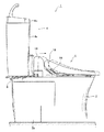
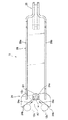
図1は本発明の一実施形態によるトイレ装置の側面図である。図1に示すように、符号1は本発明の一実施形態によるトイレ装置を示し、このトイレ装置1は、陶器等からなる便器本体2を備えている。また、便器本体2の側部には、中央から後方側にかけて外装カバー2aが取り付けられている。
つぎに、本実施形態のトイレ装置1は、便器本体2の後方側上部に固定され、この便器本体2を洗浄する洗浄水を貯える洗浄水タンク装置4と、洗浄水タンク装置4の前方側に配置され且つ便器本体2の上面に着脱可能に設けられた衛生洗浄装置6を備えている。
さらに、トイレ装置1は、便器本体2の後方側上部と洗浄水タンク装置4の底部との間に取り付けられ、衛生洗浄装置6に給水する衛生洗浄装置用給水管8を保持する保持部材10を備えている。
Hereinafter, a toilet apparatus according to an embodiment of the present invention will be described with reference to the accompanying drawings.
FIG. 1 is a side view of a toilet apparatus according to an embodiment of the present invention. As shown in FIG. 1, the code | symbol 1 shows the toilet device by one Embodiment of this invention, This toilet device 1 is provided with the
Next, the toilet apparatus 1 of the present embodiment is fixed to the upper rear side of the
Furthermore, the toilet device 1 is attached between the rear upper part of the
なお、本実施形態のトイレ装置1においては、一例として、便器本体2が床に設置された床置き式のトイレ装置ついて説明するが、便器本体2からトイレ装置1の外部への排水については、トイレ装置1が配置される室内の壁側(例えば、便器本体の背面側等)に向けて排水されるような形態であってもよいし、床下側に排水されるような形態でもよい。
さらに、トイレ装置1の便器本体2を洗浄する方式についても、特定の洗浄方式に限定されず、洗浄水の落差による流水作用で汚物を押し流す洗い落し式のような洗浄方式であってもよいし、サイホン作用を利用するような洗浄方式であってもよい。
In the toilet apparatus 1 of the present embodiment, as an example, a floor-standing toilet apparatus in which the
Furthermore, the method of cleaning the
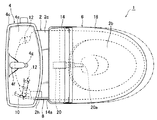
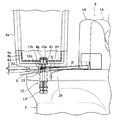
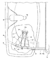
つぎに、図2は本発明の一実施形態によるトイレ装置の平面図であり、図3は本発明の一実施形態によるトイレ装置から洗浄水タンク装置及び衛生洗浄装置を取り外した状態の便器本体及び保持部材を示す平面図である。また、図4は本発明の一実施形態によるトイレ装置の便器本体の外装カバーを取り外した状態で洗浄水タンク装置の側面を一部破断して見た部分側面断面図である。さらに、図5は本発明の一実施形態によるトイレ装置における便器本体、洗浄水タンク装置、及び、保持部材を背面側から見た部分拡大断面図である。また、図6は、本発明の一実施形態によるトイレ装置における便器本体と洗浄水タンク装置との間に取り付けられた状態の保持部材を上方側から見た部分拡大平面図である。 Next, FIG. 2 is a plan view of a toilet device according to an embodiment of the present invention, and FIG. 3 is a toilet body with the cleaning water tank device and the sanitary cleaning device removed from the toilet device according to an embodiment of the present invention. It is a top view which shows a holding member. FIG. 4 is a partial cross-sectional side view of the flush water tank apparatus with the side surface partially broken away with the exterior cover of the toilet body of the toilet apparatus according to an embodiment of the present invention removed. Furthermore, FIG. 5 is the elements on larger scale which looked at the toilet bowl main body, the washing water tank apparatus, and the holding member in the toilet apparatus by one Embodiment of this invention from the back side. Moreover, FIG. 6 is the elements on larger scale which looked at the holding member of the state attached between the toilet bowl main body and the washing water tank apparatus in the toilet apparatus by one Embodiment of this invention from the upper side.
まず、図1、図2、図4及び図5に示すように、洗浄水タンク装置4は、陶器製の外装タンク4aと、この外装タンク4aの内方に配置され、洗浄水が貯水される樹脂製の貯水タンク4bと、外装タンク4aに載せられた蓋体4cと、外装タンク4aと貯水タンク4bとの間に設けられた断熱部材4dを備えている。
また、図2に示すように、蓋体4cには、手洗い鉢4eが形成され、この手洗い鉢4eの後方側には、手洗い用の水を吐水する手洗い用カラン4fが設けられている。手洗い用カラン4fから吐水された手洗い鉢4eの水は、手洗い鉢4eに形成された吐水口(流入口)4gにより、貯水タンク4bに流入されるようになっている。
First, as shown in FIGS. 1, 2, 4, and 5, the washing
As shown in FIG. 2, the
つぎに、図3及び図4に示すように、便器本体2のボウル部2bよりも後方側に位置する便器本体2の上面2cで且つ洗浄水タンク装置4の外装タンク4aの底部と上下方向に対向する領域A1には、同一の高さで上方に突出した複数の突起2dが設けられており、洗浄水タンク装置4の外装タンク4aの底部が便器本体2の突起2d上に配置されるようになっている。
また、洗浄水タンク装置4の外装タンク4aの底部が便器本体2の突起2d上に配置された状態では、外装タンク4aの底部とこれに対向する便器本体2の後方側の上面2cの領域A1の突起2d以外の領域との間に上下方向に所定間隔d(例えば、10mm)が形成されるようになっている。
Next, as shown in FIGS. 3 and 4, the
In the state where the bottom of the
さらに、図2〜図5に示すように、本実施形態のトイレ装置1は、洗浄水タンク装置4の外装タンク4aの底部が便器本体2の突起2d上に配置された状態で、洗浄水タンク装置4と便器本体2とを互いに上下方向に所定間隔d(例えば、10mm)を置いて固定する固定部材12を備えている。
この固定部材12は、外装タンク4aの底部とこれに対向する便器本体2の後方側の上面2cの領域A1に左右一対ずつ設けられている。
Furthermore, as shown in FIGS. 2 to 5, the toilet apparatus 1 of the present embodiment is configured such that the bottom of the
The fixing
また、図4及び図5に示すように、各固定部材12の頭部12aは、貯水タンク4bの底部に位置する所定の固定部材取付部4gに下側から取り付けられている。
さらに、固定部材12の首部12bは、貯水タンク4bの固定部材取付部4gの下方に位置する外装タンク4aの固定部材取付部4hに取り付けられた後、固定部材12の軸部12cが外装タンク4aの底部を下方に貫き、外装タンク4aの下側面でリングナット12dによって締結され、固定部材12が洗浄水タンク装置4に固定されている。
As shown in FIGS. 4 and 5, the
Further, after the
また、図3及び図5に示すように、便器本体2の後方側の領域A1は、上下方向に所定の厚みtを備え、この便器本体2の後方側の領域A1には、一対の取付穴2e,2fが便器本体2の後方側部分を上下方向に貫くように形成されている。
さらに、各固定部材12の軸部12cの先端部12eは、それぞれに対応する取付穴2e,2fを貫いて延びた後、便器本体2の後方側領域A1の下側部分2gでナットユニット12fが取り付けられ、各固定部材12が便器本体2の後方側領域A1に固定されている。
As shown in FIGS. 3 and 5, the rear area A1 of the
Further, the
図1及び図2に示すように、衛生洗浄装置6は、便器本体2のボウル部2bよりも後方側に位置する便器本体2の上面2cに着脱可能に取り付けられ且つ前後方向に摺動可能である衛生洗浄装置本体14と、この衛生洗浄装置本体14の前方側に衛生洗浄装置本体14を中心に上下方向に回動可能に取り付けられた便座16と、衛生洗浄装置本体14の前方側且つ便座16の上側に衛生洗浄装置本体14を中心に上下方向に回動可能に取り付けられ、便器本体2のボウル部2bの上方を開閉する便蓋18を備えている。
As shown in FIGS. 1 and 2, the
図2に示すように、衛生洗浄装置本体14は、複数の細長い円筒状部材が軸方向に入れ子状に伸長可能に設けられた吐水ノズル20を備えている。この衛生洗浄装置本体14の吐水ノズル20は、本実施形態では一例として3つの円筒状部材が入れ子状に重ねて設けられている。使用者が衛生洗浄装置6による局部洗浄を行う際、吐水ノズル20が前方へ伸長し、吐水ノズル20の先端部に位置する噴射部20aが前方のボウル部2b内の空間に向かって推進するようになっている。
As shown in FIG. 2, the sanitary washing device
また、衛生洗浄装置本体14の内部には、吐水ノズル20に供給するための水を貯水するサブタンク(図示せず)や、このサブタンク(図示せず)からの水を適温に温めて温水にする熱交換器(図示せず)、サブタンク(図示せず)から熱交換器(図示せず)を通過させて吐水ノズル20に供給するポンプ(図示せず)等の機器や、これらの機器の作動を制御する制御基板(図示せず)等が内蔵されている。
Further, inside the sanitary washing device
つぎに、図1、図2及び図4に示すように、衛生洗浄装置本体14の後端部には、衛生洗浄装置本体14内のサブタンク(図示せず)に給水するための衛生洗浄装置用の給水管8が接続されている。
また、この衛生洗浄装置用の給水管8は、樹脂やゴム製の防水層と金属製のメッシュの被覆層等を積層した材料で作られて比較的可撓性を備え、衛生洗浄装置本体14の後端部に位置する給水管接続部14aから後方側に延びている。この給水管8の上流側端部は、便器本体2の後方側に位置し且つ水道等の給水源(図示せず)と通ずる給水栓(図示せず)に接続されている。
Next, as shown in FIGS. 1, 2, and 4, the sanitary washing apparatus
The
さらに、図2及び図4〜図6に示すように、衛生洗浄装置用の給水管8は、衛生洗浄装置本体14の給水管接続部14aから便器本体2の後方側上部と洗浄水タンク装置4の底部との間の領域まで延び、この領域内で、便器本体2の側縁部2h及び外装カバー2aよりも内側に位置するように、保持部材10によって外側から内側に向けて且つ上下方向に保持されている。
Further, as shown in FIG. 2 and FIGS. 4 to 6, the
さらに、衛生洗浄装置本体14は、便器本体2のボウル部2bよりも後方側に位置する便器本体2の上面2cに固定されたベースプレート22(図3参照)に着脱可能に取り付けられている。
便器本体2の上面2cにおける洗浄水タンク装置4の外装タンク4aと衛生洗浄装置本体14との間の領域について清掃を行ったり、衛生洗浄装置6自体の清掃やメンテナンス等を行ったりする際には、衛生洗浄装置本体14について、図1、図2及び図4に実線で示す所定の取付位置から、図1、図2及び図4に鎖線で示す所定の移動位置まで前方側へ移動させることにより、便座16及び便蓋18も衛生洗浄装置本体14と共に移動させることができるようになっている。
Furthermore, the sanitary
When cleaning the area between the
また、図3〜図6に示すように、便器本体2は、その後方側上面2cの角部に形成されて給水管8をガイドするためのガイド面2iを備え、このガイド面2iにより、衛生洗浄装置本体14の給水管接続部14aから後方側に延びて保持部材10によって保持された給水管8が、便器本体2のガイド面2iと洗浄水タンク装置4の底部との間でほぼ水平な状態で後方側に延びるようにガイドされるようになっている。
Moreover, as shown in FIGS. 3-6, the
さらに、便器本体のガイド面2iは、前方側から後方側にかけて斜め下方に且つなだらかな曲面状に降下して延びており、ガイド面2iの後端部2jは、洗浄水タンク装置4の外装タンク4aの前端部よりも後方側に延びている。
このようなガイド面2iにより、例えば、衛生洗浄装置6を便器本体2から着脱する際に、衛生洗浄装置6を便器本体2の上面2cに対して前後方向に移動させたとしても、給水管8が便器本体2のガイド面2iによって下側から支持されてほぼ水平な状態に維持されるようになっている。さらに、便器本体2を上方から見た場合には、洗浄水タンク装置4の外装タンク4aの前端部よりも後方側は、ガイド面2iしか見えず、ガイド面2iと洗浄水タンク装置4の底部との間の隙間が目立たなくすることができると共に、ガイド面2iよりも背面側や便器本体2の下方の床面等も見えないようにすることができるようになっている。
Furthermore, the
Even if the
つぎに、本実施形態のトイレ装置1の保持部材10の詳細について説明する。
図7は本発明の一実施形態によるトイレ装置の保持部材の平面図であり、図8は本発明の一実施形態によるトイレ装置の保持部材の背面図である。
Below, the detail of the holding
FIG. 7 is a plan view of the holding member of the toilet apparatus according to the embodiment of the present invention, and FIG. 8 is a rear view of the holding member of the toilet apparatus according to the embodiment of the present invention.
図5〜図8に示すように、保持部材10は、その一端部に設けられ且つ固定部材12によって固定された洗浄水タンク装置4と便器本体2との上下方向の所定間隔dの部分に位置する固定部材12の軸部12cに着脱可能に取り付けられる取付部24と、この取付部24から長手方向に延びた保持部材10の他端部に設けられ且つ衛生洗浄装置用の給水管8を保持する保持部26と、この保持部26と取付部24との間でほぼ直線状に延びるように形成されている中間部28を備えている。これらの取付部24から中間部28を経て保持部26までの保持部材10の全体部分は、樹脂材料等により一体的に形成されている。
As shown in FIG. 5 to FIG. 8, the holding
また、図7に示すように、保持部材10の取付部24には、固定部材12の軸部12cに係合可能な係合穴24aが形成されており、この係合穴24aの外側周縁の一部が開放されている。ここで、係合穴24aは、固定部材12の丸棒形状の軸部12cの直径とほぼ等しい直径D1を備えている。
Further, as shown in FIG. 7, the
さらに、保持部材10の取付部24は、一対のガイド部24bを備え、この一対のガイド部24bは、係合穴24aの開放された外側周縁部を基端として、この基端から外側に向かう先端部にかけてほぼテーパー状に拡張するように形成されている。
Further, the mounting
また、保持部材10の取付部24を洗浄水タンク装置4と便器本体2との間の固定部材12の軸部12cに取り付ける際には、まず、保持部材10の取付部24の一対のガイド部24b同士で挟まれた所定の領域A2内に固定部材12の軸部12cが挿入されるように、保持部材10の取付部24を固定部材12の軸部12cに近づけることにより、保持部材10の取付部24の一対のガイド部24bのいずれかのガイド面24cに固定部材12の軸部12cを接触させるようになっている。
なお、図7の符号12c’と符号12c”については、保持部材10の取付部24を固定部材12の軸部12cに押し付けることにより、保持部材10の取付部24の一対のガイド部24bのいずれかのガイド面24cに接触した状態の固定部材12の軸部の例をそれぞれ示している。
When attaching the
In addition, about the code |
さらに、保持部材10の取付部24の一対のガイド部24bのいずれかのガイド面24cに固定部材12の軸部12c’又は12c”が接触した後、保持部材10の取付部24を固定部材12の軸部12c’又は12c”にさらに近づけることにより、固定部材12の軸部12c’又は12c”が、接触しているガイド面24cに沿ってガイド部24bの基端側へ移動して係合穴24aに向ってガイドされ(図7の軸部12c’及び12c”に関する矢印方向参照)、最終的には、係合穴24aに係合して嵌め込まれるようになっている。
Further, after the
また、図7に示すように、保持部材10の取付部24の一対のガイド部24bの基端部同士の間隔wは、固定部材12の軸部12c及び係合穴24aの直径D1よりも小さく設定されているため、固定部材12の軸部12cがガイド面24cとの接触状態から係合穴24aとの嵌合状態に移行する際には、一対のガイド部24bの基端部同士が固定部材12の軸部12cとの接触によって一時的に弾性変形し、ガイド部24bの基端部同士の間隔wが固定部材12の軸部12cが通過可能に拡張し、固定部材12の軸部12cが係合穴24aとの嵌合を完了した時点で元の弾性変形前の状態に戻るようになっている。
Moreover, as shown in FIG. 7, the space | interval w of the base end part of a pair of
保持部材10の保持部26は、その長手方向内側から外側に向って延びた外側端部が下方側に屈曲し、この屈曲した部分の下端から内側に屈曲することにより、ほぼ半円弧状に形成されたリム部26aを備え、このリム部26aの内周側の領域A3(図5及び図8参照)は、衛生洗浄装置用の給水管8が挿入可能な大きさとなっている。
なお、本実施形態では、リム部26aの形状については、図5及び図7に示すように、ほぼ半円弧状としているが、このようなリム部26aの形状に限定されず、コの字形等の矩形形状や半円弧以外の形状に設定してもよい。
The holding
In the present embodiment, the shape of the
また、リム部26aは、保持部材10の取付部24側から中間部28で長手方向にほぼ直線状に延びた状態からほぼ半円弧状に屈曲した状態に遷移する上端側遷移部26bと、この上端側遷移部26bから鉛直方向面内でほぼ半円弧状に延びた状態から再び保持部材10の取付部24側に向って直線状に延びた状態に遷移する下端側遷移部26cを備えている。
さらに、リム部26aは、下端側遷移部26cから保持部材10の取付部24側に向って中間部28とほぼ平行に所定距離直線状に延びる下端側直線部26dと、この下端側直線部26dの内側端部(取付部24側の端部)から上方に所定距離突出する突起部26eを備えている。なお、この突起部26eについては省略してもよい。
The
Further, the
また、図7に示すように、リム部26aの上端側遷移部26bと下端側遷移部26cとの上下方向の直線距離h1は、給水管8の断面の最大直径D2よりも大きく、リム部26aの鉛直方向面内の内周側領域A3の断面の大きさも給水管8の断面の大きさよりも大きくなるように設定されている。
Moreover, as shown in FIG. 7, the linear distance h1 of the up-down direction of the upper end
図5、図7及び図8に示すように、保持部材10の中間部28は、横幅方向に所定間隔を置いて形成され且つ長手方向に沿って所定距離上方に突出する一対のフランジ28a,28bを備えている。
また、両フランジ28a,28bの高さ寸法h2は、保持部材10が洗浄水タンク装置4と便器本体2との上下方向の所定間隔d内に取り付け可能となるように、洗浄水タンク装置4と便器本体2との所定間隔dよりもわずかに小さく設定されている。
As shown in FIGS. 5, 7, and 8, the
Further, the height h2 of the
さらに、これらのフランジ28a,28bは、保持部材10を洗浄水タンク装置4と便器本体2と間に挿入して取り付ける際に、保持部材10のガタツキを低減させて保持部材10の取り付けをスムーズに行うためのスペーサーとして機能すると共に、保持部材10自体の曲げ強度やねじり強度を高めることができるようになっている。
Furthermore, when the holding
つぎに、図6〜図8を参照して、本実施形態のトイレ装置1の保持部材10を洗浄水タンク装置4と便器本体2と間の固定部材12に取り付ける方法について説明する。
ここで、図6の保持部材10’及び10”は、保持部材10をトイレ装置1の外側から洗浄水タンク装置4と便器本体2と間に挿入して取り付ける際の取付方向とは異なるいくつかの方向から取り付けた場合のそれぞれの例を示している。
図6に示すように、保持部材10(10’又は10”)を洗浄水タンク装置4と便器本体2と間に挿入して取り付ける際には、まず、給水管8を保持部材10の保持部26のリム部26aの内周側領域A3(図8参照)内に挿入した上で、保持部材10の取付部24を固定部材12の軸部12cに近づけることにより、保持部材10の取付部24の一対のガイド部24bで挟まれた所定の領域A2(図7参照)内に固定部材12の軸部12cを挿入し、保持部材10の取付部24の一対のガイド部24bのいずれかのガイド面24cに固定部材12の軸部12cを接触させる。この際、保持部材10(10’又は10”)の取付部24の一対のガイド部24bにより、保持部材10(10’又は10”)の取付方向にかかわらず、固定部材12の軸部12cが保持部材10(10’又は10”)の取付部24の一対のガイド部24b内に挿入される。
Next, a method for attaching the holding
Here, the holding
As shown in FIG. 6, when the holding member 10 (10 ′ or 10 ″) is inserted and attached between the flush
つぎに、保持部材10の取付部24の一対のガイド部24bのいずれかのガイド面24cに固定部材12の軸部12c’又は12c”が接触した後、保持部材10の取付部24を固定部材12の軸部12c’又は12c”にさらに押し付けることにより、固定部材12の軸部12c’又は12c”をガイド面24cに沿って接触させながらガイド部24b基端側へ移動させ(図7の軸部12c’及び12c”に関する矢印方向参照)、係合穴24aに向ってガイドし、固定部材12の軸部12cが保持部材10の取付部24の係合穴24aに嵌め込まれる。
Next, after the
保持部材10の取り付け後、保持部材10の取付角度の調整が必要な場合には、固定部材12の軸部12cが保持部材10の取付部24の係合穴24aに嵌め込まれた状態で保持部材10を固定部材12の軸部12cを中心に回動させる。このとき、保持部材10の保持部26のリム部26aの内周側領域A3で保持された給水管8は、保持部材10の取付方向にかかわらず、リム部26aの内周側領域A3から外れることなく、便器本体2の側縁部2h及び外装カバー2aよりも内側に位置し、且つ便器本体2のガイド面2iと洗浄水タンク装置4の底部との間でほぼ水平な状態で後方側に延びた状態が維持される。
When it is necessary to adjust the mounting angle of the holding
つぎに、本発明の一実施形態によるトイレ装置の作用を説明する。
例えば、便器本体2の上面2cにおける洗浄水タンク装置4の外装タンク4aと衛生洗浄装置本体14との間の領域について清掃を行ったり、衛生洗浄装置6自体の清掃やメンテナンス等を行ったりする際、衛生洗浄装置6について、図1、図2及び図4に実線で示す所定の取付位置から、図1、図2及び図4に鎖線で示す所定の移動位置まで前方側へ移動させると、衛生洗浄装置本体14の給水管接続部14aに接続されている衛生洗浄装置用の給水管8が前方側へ引き出される。
この際、衛生洗浄装置本体14の給水管接続部14aから後方側へ延びる給水管8は、その一部が便器本体2のガイド面2iによって下側から支持されてほぼ水平な状態に維持され、便器本体2のガイド面2iよりも後方側の領域で、保持部材10の保持部26のリム部26aにより、便器本体2の側縁部2h及び外装カバー2aよりも内側に位置するように保持される。
Next, the operation of the toilet apparatus according to one embodiment of the present invention will be described.
For example, when cleaning the area between the
At this time, a part of the
上述した本発明の実施形態によるトイレ装置1によれば、便器本体2の上面2cにおける洗浄水タンク装置4の外装タンク4aと衛生洗浄装置本体14との間の領域について清掃を行ったり、衛生洗浄装置6自体の清掃やメンテナンス等を行ったりする際に、衛生洗浄装置6を前方側へ移動させて衛生洗浄装置用の給水管8を前方側へ引き出すと、給水管8の一部が便器本体2のガイド面2iによって下側から支持されてほぼ水平な状態に維持され、便器本体2のガイド面2iよりも後方側の領域で、保持部材10の保持部26のリム部26aにより、便器本体2の側縁部2h及び外装カバー2aよりも内側に位置するように保持される。この結果、可撓性の給水管8が便器本体2の側部よりも外側に跳び出すことを防ぐことができ、給水管8が便器本体2の側部よりも外側に露出して外部から損傷を受けることを防ぐと共に、美観を向上させることができる。また、衛生洗浄装置6を便器本体2から着脱するか否かにかかわらず、便器本体2のガイド面2iや保持部材10の保持部26により、衛生洗浄装置6の後部から後方側に延びた給水管8がほぼ水平な状態で維持されるため、可撓性の給水管が周囲に引っ掛かったり、座屈したりすることによって給水管8に亀裂が入る等の給水管の損傷を防ぐことができ、給水管8の信頼性を向上させることができる。
According to the toilet device 1 according to the above-described embodiment of the present invention, the region between the
また、本実施形態によるトイレ装置1によれば、保持部材10を便器本体2の後方側上面2cと洗浄水タンク装置4の底部との間に取り付けて固定する際に、便器本体2の後方側上部と洗浄水タンク装置4の底部とを所定間隔dを置いて固定する固定部材12を利用し、この固定部材12の軸部12cに保持部材10の取付部24を取り付けて固定することができる。したがって、保持部材10を便器本体2及び洗浄水タンク装置に対して固定するための手段を新たに設ける必要がない。また、便器本体2の後方側上部と洗浄水タンク装置4の底部とを固定する固定部材12さえあれば、この固定部材12の軸部12cに保持部材10の取付部24を容易に取り付けることができるため、保持部材10の取付方向等の制約を受けにくくすることができる。
Further, according to the toilet device 1 according to the present embodiment, when the holding
さらに、本実施形態によるトイレ装置1によれば、保持部材10に加えて、便器本体2の後方側上面2cの角部に形成されたガイド面2iと洗浄水タンク装置4の底部とにより、衛生洗浄装置6の後部から後方側に延びた給水管8がほぼ水平な状態になるようにガイドして維持することができるため、例えば、衛生洗浄装置6を便器本体2から着脱する際に、衛生洗浄装置6を便器本体2の上面2cに対して前後方向に移動させたとしても、給水管をほぼ水平な状態に維持することができる。したがって、給水管8が周囲に引っ掛かったり、座屈したりして損傷するようなことがなく、給水管8の信頼性をより向上させることができる。
Furthermore, according to the toilet apparatus 1 according to the present embodiment, in addition to the holding
また、本実施形態によるトイレ装置1によれば、便器本体2のガイド面2iの後端部2jが洗浄水タンク装置4の外装タンク4aの前端部よりも後方側に延びているため、衛生洗浄装置6を便器本体2から着脱する際に、衛生洗浄装置6を便器本体2の上面2cに対して前後方向に移動させたとしても、給水管8をほぼ水平な状態により確実に維持することができるため、給水管8が座屈したりして損傷するようなことがなく、給水管8の信頼性をより向上させることができる。また、便器本体8を上方から見た場合には、洗浄水タンク装置4の外装タンク4aの前端部より前方側の便器本体2の部分と、洗浄水タンク装置4の外装タンク4aの前端部よりも後方側に延びるガイド面2iの部分しか見えないため、便器本体2のガイド面2iと洗浄水タンク装置4の外装タンク4aの底部との間の隙間を目立たないようにすることができる。また、便器本体2のガイド面2iよりも背面側の領域や便器本体2の下方の床面等も見えないようにすることができるため、外観性を向上させることができる。
Further, according to the toilet apparatus 1 according to the present embodiment, the
さらに、本実施形態によるトイレ装置1によれば、保持部材10の取付部24を固定部材12の軸部12cに取り付ける際に、保持部材10の取付部24の一対のガイド部24bで挟まれた所定の領域A2内に固定部材12の軸部12cが挿入されるように、保持部材10の取付部24を固定部材12の軸部12cに近づけた後、保持部材10の取付部24の一対のガイド部24bのいずれかのガイド面24cに固定部材12の軸部12cを接触させた後、固定部材12の軸部12cを、保持部材10の取付部24のガイド部24bのガイド面24cに沿ってガイド部24bの基端側へ移動させて係合穴24aに向ってガイドして係合穴24aに嵌め込むことができる。
このとき、保持部材10の取付部24の一対のガイド部24bがテーパー状に拡張するしているため、固定部材12の軸部12cに対する保持部材10の取付部24の取付方向にかかわらず、保持部材10の取付部24のガイド部24bの所定の領域A2内に固定部材12の軸部12cを挿入しやすくすることができる。そして、保持部材10の取付部24のガイド部24bの所定の領域A2内に固定部材12の軸部12cを挿入後、固定部材12の軸部12cに保持部材10の取付部24のガイド部24bのいずれかの箇所を接触させながら、固定部材12の軸部12cに保持部材10の取付部24のガイド部24bを押し付けてテーパー状のガイド部24bのガイド面24cに沿わせることにより、保持部材10の取付部24の係合穴24aに固定部材12の軸部12cを容易にガイドすることができ、固定部材12の軸部12cに保持部材12の取付部24の係合穴24aを確実に係合して固定することができる。
Furthermore, according to the toilet apparatus 1 according to the present embodiment, when the
At this time, since the pair of
また、本実施形態によるトイレ装置1によれば、保持部材10の保持部26のリム部26aの内周側において、給水管8を外側から内側に向けて且つ上下方向に確実に保持することができるため、給水管8を便器本体2の側縁部2h及び外装カバー2aよりも内側に位置するように保持することができる。したがって、衛生洗浄装置6を便器本体2から着脱する際に、衛生洗浄装置6を便器本体2の上面2cに対して前後方向に移動させたとしても、給水管をほぼ水平な状態に維持することができる。したがって、給水管8が周囲に引っ掛かったり、座屈したりして損傷するようなことがなく、給水管8の信頼性をより向上させることができる。
Further, according to the toilet apparatus 1 according to the present embodiment, the
さらに、本実施形態によるトイレ装置1によれば、保持部材10の保持部26のリム部26aの突起部26eにより、リム部26aの所定の内周側領域A3に給水管8を挿入するべき領域を画定することができるため、給水管8をリム部26aの所定の内周側領域A3に挿入しやすくすることができると共に、このリム部26aの所定の内周側領域A3内に挿入した給水管8が落下するのを防ぐことができる。したがって、衛生洗浄装置6を便器本体2から着脱する際に、衛生洗浄装置6を便器本体2の上面2cに対して前後方向に移動させたとしても、給水管をほぼ水平な状態に維持することができる。
Furthermore, according to the toilet apparatus 1 according to the present embodiment, the region in which the
1 トイレ装置
2 便器本体
2a 外装カバー
2b ボウル部
2c 上面
2d 突起
2e 取付穴
2f 取付穴
2g 便器本体の後方側領域の下側部分
2h 便器本体の側縁部
2i 便器本体のガイド面
2j 便器本体のガイド面の後端部
4 洗浄水タンク装置
4a 外装タンク
4b 貯水タンク
4c 蓋体
4d 断熱部材
4e 手洗い鉢
4f 手洗い用カラン
4g 貯水タンクの固定部材取付部
4h 外装タンクの固定部材取付部
6 衛生洗浄装置
8 衛生洗浄装置用給水管
10 保持部材
12 固定部材(固定手段)
12a 固定部材の頭部
12b 固定部材の首部
12c 固定部材の軸部
12d リングナット
12e 固定部材の軸部の先端部
12f ナットユニット
14 衛生洗浄装置本体
14a 衛生洗浄装置本体の給水管接続部
16 便座
18 便蓋
20 吐水ノズル
20a 吐水ノズルの噴射部
22 ベースプレート
24 保持部材の取付部
24a 係合穴(係合部)
24b ガイド部
24c ガイド面
26 保持部材の保持部
26a リム部
26b リム部の上端側遷移部
26c リム部の下端側遷移部
26d リム部の下端側直線部
26e 突起部
28 保持部材の中間部
28a フランジ
28b フランジ
DESCRIPTION OF SYMBOLS 1
12a Head part of fixing
Claims (7)
便器本体と、
この便器本体の後方側上部に固定され、上記便器本体を洗浄する洗浄水を貯える洗浄水タンクと、
使用者の人体局部を洗浄する吐水ノズルを備え、上記便器本体の上面に着脱可能に取り付けられた衛生洗浄装置と、
この衛生洗浄装置の後部に接続され、上記衛生洗浄装置に給水する可撓性の給水管と、
上記便器本体の後方側上部と上記洗浄水タンクの底部との間に取り付けられ、上記給水管を保持する保持部材と、を有し、
この保持部材は、上記給水管が上記衛生洗浄装置の後部から上記便器本体の後方側上部と上記洗浄水タンクの底部との間の領域を経て後方側に延びて且つ上記便器本体の側部よりも内側に位置するように、上記給水管を外側から内側に向けて且つ上下方向に保持する保持部を備えていることを特徴とするトイレ装置。 A toilet device that is washed with washing water and discharges filth,
The toilet body,
A wash water tank fixed to the upper rear side of the toilet body and storing wash water for washing the toilet body;
A sanitary washing device comprising a water discharge nozzle for washing the user's body part, and detachably attached to the upper surface of the toilet body,
A flexible water supply pipe connected to the rear portion of the sanitary washing device and supplying water to the sanitary washing device;
A holding member that is attached between the rear upper part of the toilet body and the bottom of the flush water tank and holds the water supply pipe;
In this holding member, the water supply pipe extends from the rear part of the sanitary washing device to the rear side through a region between the rear upper part of the toilet body and the bottom part of the cleaning water tank, and from the side part of the toilet body. A toilet apparatus comprising a holding portion that holds the water supply pipe in the vertical direction from the outside to the inside so that the water supply pipe is also located inside.
Priority Applications (1)
| Application Number | Priority Date | Filing Date | Title |
|---|---|---|---|
| JP2011028769A JP5652751B2 (en) | 2011-02-14 | 2011-02-14 | Toilet equipment |
Applications Claiming Priority (1)
| Application Number | Priority Date | Filing Date | Title |
|---|---|---|---|
| JP2011028769A JP5652751B2 (en) | 2011-02-14 | 2011-02-14 | Toilet equipment |
Publications (2)
| Publication Number | Publication Date |
|---|---|
| JP2012167478A true JP2012167478A (en) | 2012-09-06 |
| JP5652751B2 JP5652751B2 (en) | 2015-01-14 |
Family
ID=46971874
Family Applications (1)
| Application Number | Title | Priority Date | Filing Date |
|---|---|---|---|
| JP2011028769A Active JP5652751B2 (en) | 2011-02-14 | 2011-02-14 | Toilet equipment |
Country Status (1)
| Country | Link |
|---|---|
| JP (1) | JP5652751B2 (en) |
Cited By (3)
| Publication number | Priority date | Publication date | Assignee | Title |
|---|---|---|---|---|
| JP2019138022A (en) * | 2018-02-08 | 2019-08-22 | Toto株式会社 | Toilet device |
| JP2020133337A (en) * | 2019-02-25 | 2020-08-31 | Toto株式会社 | Toilet device |
| JP2023034308A (en) * | 2021-08-30 | 2023-03-13 | Toto株式会社 | Flush toilet bowl |
Citations (1)
| Publication number | Priority date | Publication date | Assignee | Title |
|---|---|---|---|---|
| JP2008095396A (en) * | 2006-10-12 | 2008-04-24 | Toto Ltd | Toilet device |
-
2011
- 2011-02-14 JP JP2011028769A patent/JP5652751B2/en active Active
Patent Citations (1)
| Publication number | Priority date | Publication date | Assignee | Title |
|---|---|---|---|---|
| JP2008095396A (en) * | 2006-10-12 | 2008-04-24 | Toto Ltd | Toilet device |
Cited By (5)
| Publication number | Priority date | Publication date | Assignee | Title |
|---|---|---|---|---|
| JP2019138022A (en) * | 2018-02-08 | 2019-08-22 | Toto株式会社 | Toilet device |
| JP7072782B2 (en) | 2018-02-08 | 2022-05-23 | Toto株式会社 | Toilet device |
| JP2020133337A (en) * | 2019-02-25 | 2020-08-31 | Toto株式会社 | Toilet device |
| JP7276678B2 (en) | 2019-02-25 | 2023-05-18 | Toto株式会社 | toilet equipment |
| JP2023034308A (en) * | 2021-08-30 | 2023-03-13 | Toto株式会社 | Flush toilet bowl |
Also Published As
| Publication number | Publication date |
|---|---|
| JP5652751B2 (en) | 2015-01-14 |
Similar Documents
| Publication | Publication Date | Title |
|---|---|---|
| CN103874811B (en) | Flushing type sitting wc pan and coupling device thereof | |
| JP5652751B2 (en) | Toilet equipment | |
| JP5132371B2 (en) | Western style flush toilet | |
| JP5721049B2 (en) | Toilet equipment | |
| JP6593717B2 (en) | Wall-mounted toilet device and toilet system | |
| JP2011231472A (en) | Water closet | |
| KR101359284B1 (en) | A urinal for women only | |
| JP2009052337A (en) | Faucet device | |
| JP2012197565A (en) | Sanitary washing device and water supply piping structure and attaching method of sanitary washing device | |
| KR101088997B1 (en) | Air bubble supply device for toilet bowl | |
| JP4235199B2 (en) | Western style flush toilet | |
| JP2007308912A (en) | Flush toilet bowl | |
| KR100697254B1 (en) | Cleaning device mounted on the toilet lid | |
| JP5643953B2 (en) | Hand wash water discharge device | |
| KR20150145761A (en) | Bidet apparatus having nozzle cleaning element | |
| JP6183649B2 (en) | Toilet equipment | |
| WO2013190541A1 (en) | Combined toilet bowl | |
| KR101117488B1 (en) | a faucet | |
| JP2017179957A (en) | Toilet bowl washing equipment and toilet bowl device | |
| JP2004084473A (en) | Flush toilet bowl | |
| JP4771832B2 (en) | Warm water washing toilet seat | |
| DE202005000084U1 (en) | A method for ensuring hygienic cleansing of a toilet bowl has a pump and nozzle system to project a controlled water spray into the bowl | |
| KR20090057683A (en) | Toilet seat | |
| JP2007217914A (en) | Western style toilet bowl device and male urination member used therefor | |
| JP4645582B2 (en) | Toilet seat with hot water washing and toilet equipped with the same |
Legal Events
| Date | Code | Title | Description |
|---|---|---|---|
| A621 | Written request for application examination |
Free format text: JAPANESE INTERMEDIATE CODE: A621 Effective date: 20130327 |
|
| A977 | Report on retrieval |
Free format text: JAPANESE INTERMEDIATE CODE: A971007 Effective date: 20131225 |
|
| A131 | Notification of reasons for refusal |
Free format text: JAPANESE INTERMEDIATE CODE: A131 Effective date: 20140421 |
|
| A521 | Written amendment |
Free format text: JAPANESE INTERMEDIATE CODE: A523 Effective date: 20140618 |
|
| TRDD | Decision of grant or rejection written | ||
| A01 | Written decision to grant a patent or to grant a registration (utility model) |
Free format text: JAPANESE INTERMEDIATE CODE: A01 Effective date: 20141027 |
|
| R150 | Certificate of patent or registration of utility model |
Ref document number: 5652751 Country of ref document: JP Free format text: JAPANESE INTERMEDIATE CODE: R150 |
|
| A61 | First payment of annual fees (during grant procedure) |
Free format text: JAPANESE INTERMEDIATE CODE: A61 Effective date: 20141109 |