JP2012165497A - Non-contact power supply control device and non-contact power supply system - Google Patents
Non-contact power supply control device and non-contact power supply system Download PDFInfo
- Publication number
- JP2012165497A JP2012165497A JP2011022058A JP2011022058A JP2012165497A JP 2012165497 A JP2012165497 A JP 2012165497A JP 2011022058 A JP2011022058 A JP 2011022058A JP 2011022058 A JP2011022058 A JP 2011022058A JP 2012165497 A JP2012165497 A JP 2012165497A
- Authority
- JP
- Japan
- Prior art keywords
- vehicle
- power supply
- power
- living body
- contact
- Prior art date
- Legal status (The legal status is an assumption and is not a legal conclusion. Google has not performed a legal analysis and makes no representation as to the accuracy of the status listed.)
- Granted
Links
- 238000012840 feeding operation Methods 0.000 claims abstract description 25
- 238000001514 detection method Methods 0.000 claims description 99
- 230000005672 electromagnetic field Effects 0.000 abstract description 29
- 230000002411 adverse Effects 0.000 abstract description 9
- 230000000694 effects Effects 0.000 abstract description 6
- 241001465754 Metazoa Species 0.000 abstract description 5
- 238000000034 method Methods 0.000 description 24
- 230000008569 process Effects 0.000 description 17
- 238000012545 processing Methods 0.000 description 16
- 238000004891 communication Methods 0.000 description 10
- 238000002360 preparation method Methods 0.000 description 6
- 230000002035 prolonged effect Effects 0.000 description 6
- 230000007246 mechanism Effects 0.000 description 5
- 238000013459 approach Methods 0.000 description 4
- 238000010586 diagram Methods 0.000 description 4
- 238000005286 illumination Methods 0.000 description 4
- 238000003384 imaging method Methods 0.000 description 4
- 230000005540 biological transmission Effects 0.000 description 3
- 230000008859 change Effects 0.000 description 2
- 230000001133 acceleration Effects 0.000 description 1
- 238000004378 air conditioning Methods 0.000 description 1
- 238000004458 analytical method Methods 0.000 description 1
- 230000004397 blinking Effects 0.000 description 1
- 238000007796 conventional method Methods 0.000 description 1
- 238000001816 cooling Methods 0.000 description 1
- 230000008878 coupling Effects 0.000 description 1
- 238000010168 coupling process Methods 0.000 description 1
- 238000005859 coupling reaction Methods 0.000 description 1
- 238000007599 discharging Methods 0.000 description 1
- 230000005611 electricity Effects 0.000 description 1
- 230000005674 electromagnetic induction Effects 0.000 description 1
- 238000010191 image analysis Methods 0.000 description 1
- 239000004973 liquid crystal related substance Substances 0.000 description 1
- 230000007257 malfunction Effects 0.000 description 1
- 238000012986 modification Methods 0.000 description 1
- 230000004048 modification Effects 0.000 description 1
- 238000010248 power generation Methods 0.000 description 1
- 239000003507 refrigerant Substances 0.000 description 1
- 238000005057 refrigeration Methods 0.000 description 1
- 230000001172 regenerating effect Effects 0.000 description 1
- 238000012795 verification Methods 0.000 description 1
Images


Classifications
-
- B—PERFORMING OPERATIONS; TRANSPORTING
- B60—VEHICLES IN GENERAL
- B60L—PROPULSION OF ELECTRICALLY-PROPELLED VEHICLES; SUPPLYING ELECTRIC POWER FOR AUXILIARY EQUIPMENT OF ELECTRICALLY-PROPELLED VEHICLES; ELECTRODYNAMIC BRAKE SYSTEMS FOR VEHICLES IN GENERAL; MAGNETIC SUSPENSION OR LEVITATION FOR VEHICLES; MONITORING OPERATING VARIABLES OF ELECTRICALLY-PROPELLED VEHICLES; ELECTRIC SAFETY DEVICES FOR ELECTRICALLY-PROPELLED VEHICLES
- B60L15/00—Methods, circuits, or devices for controlling the traction-motor speed of electrically-propelled vehicles
- B60L15/20—Methods, circuits, or devices for controlling the traction-motor speed of electrically-propelled vehicles for control of the vehicle or its driving motor to achieve a desired performance, e.g. speed, torque, programmed variation of speed
- B60L15/2009—Methods, circuits, or devices for controlling the traction-motor speed of electrically-propelled vehicles for control of the vehicle or its driving motor to achieve a desired performance, e.g. speed, torque, programmed variation of speed for braking
-
- B—PERFORMING OPERATIONS; TRANSPORTING
- B60—VEHICLES IN GENERAL
- B60L—PROPULSION OF ELECTRICALLY-PROPELLED VEHICLES; SUPPLYING ELECTRIC POWER FOR AUXILIARY EQUIPMENT OF ELECTRICALLY-PROPELLED VEHICLES; ELECTRODYNAMIC BRAKE SYSTEMS FOR VEHICLES IN GENERAL; MAGNETIC SUSPENSION OR LEVITATION FOR VEHICLES; MONITORING OPERATING VARIABLES OF ELECTRICALLY-PROPELLED VEHICLES; ELECTRIC SAFETY DEVICES FOR ELECTRICALLY-PROPELLED VEHICLES
- B60L1/00—Supplying electric power to auxiliary equipment of vehicles
- B60L1/003—Supplying electric power to auxiliary equipment of vehicles to auxiliary motors, e.g. for pumps, compressors
-
- B—PERFORMING OPERATIONS; TRANSPORTING
- B60—VEHICLES IN GENERAL
- B60L—PROPULSION OF ELECTRICALLY-PROPELLED VEHICLES; SUPPLYING ELECTRIC POWER FOR AUXILIARY EQUIPMENT OF ELECTRICALLY-PROPELLED VEHICLES; ELECTRODYNAMIC BRAKE SYSTEMS FOR VEHICLES IN GENERAL; MAGNETIC SUSPENSION OR LEVITATION FOR VEHICLES; MONITORING OPERATING VARIABLES OF ELECTRICALLY-PROPELLED VEHICLES; ELECTRIC SAFETY DEVICES FOR ELECTRICALLY-PROPELLED VEHICLES
- B60L1/00—Supplying electric power to auxiliary equipment of vehicles
- B60L1/02—Supplying electric power to auxiliary equipment of vehicles to electric heating circuits
-
- B—PERFORMING OPERATIONS; TRANSPORTING
- B60—VEHICLES IN GENERAL
- B60L—PROPULSION OF ELECTRICALLY-PROPELLED VEHICLES; SUPPLYING ELECTRIC POWER FOR AUXILIARY EQUIPMENT OF ELECTRICALLY-PROPELLED VEHICLES; ELECTRODYNAMIC BRAKE SYSTEMS FOR VEHICLES IN GENERAL; MAGNETIC SUSPENSION OR LEVITATION FOR VEHICLES; MONITORING OPERATING VARIABLES OF ELECTRICALLY-PROPELLED VEHICLES; ELECTRIC SAFETY DEVICES FOR ELECTRICALLY-PROPELLED VEHICLES
- B60L3/00—Electric devices on electrically-propelled vehicles for safety purposes; Monitoring operating variables, e.g. speed, deceleration or energy consumption
- B60L3/0023—Detecting, eliminating, remedying or compensating for drive train abnormalities, e.g. failures within the drive train
-
- B—PERFORMING OPERATIONS; TRANSPORTING
- B60—VEHICLES IN GENERAL
- B60L—PROPULSION OF ELECTRICALLY-PROPELLED VEHICLES; SUPPLYING ELECTRIC POWER FOR AUXILIARY EQUIPMENT OF ELECTRICALLY-PROPELLED VEHICLES; ELECTRODYNAMIC BRAKE SYSTEMS FOR VEHICLES IN GENERAL; MAGNETIC SUSPENSION OR LEVITATION FOR VEHICLES; MONITORING OPERATING VARIABLES OF ELECTRICALLY-PROPELLED VEHICLES; ELECTRIC SAFETY DEVICES FOR ELECTRICALLY-PROPELLED VEHICLES
- B60L3/00—Electric devices on electrically-propelled vehicles for safety purposes; Monitoring operating variables, e.g. speed, deceleration or energy consumption
- B60L3/04—Cutting off the power supply under fault conditions
-
- B—PERFORMING OPERATIONS; TRANSPORTING
- B60—VEHICLES IN GENERAL
- B60L—PROPULSION OF ELECTRICALLY-PROPELLED VEHICLES; SUPPLYING ELECTRIC POWER FOR AUXILIARY EQUIPMENT OF ELECTRICALLY-PROPELLED VEHICLES; ELECTRODYNAMIC BRAKE SYSTEMS FOR VEHICLES IN GENERAL; MAGNETIC SUSPENSION OR LEVITATION FOR VEHICLES; MONITORING OPERATING VARIABLES OF ELECTRICALLY-PROPELLED VEHICLES; ELECTRIC SAFETY DEVICES FOR ELECTRICALLY-PROPELLED VEHICLES
- B60L50/00—Electric propulsion with power supplied within the vehicle
- B60L50/10—Electric propulsion with power supplied within the vehicle using propulsion power supplied by engine-driven generators, e.g. generators driven by combustion engines
- B60L50/16—Electric propulsion with power supplied within the vehicle using propulsion power supplied by engine-driven generators, e.g. generators driven by combustion engines with provision for separate direct mechanical propulsion
-
- B—PERFORMING OPERATIONS; TRANSPORTING
- B60—VEHICLES IN GENERAL
- B60L—PROPULSION OF ELECTRICALLY-PROPELLED VEHICLES; SUPPLYING ELECTRIC POWER FOR AUXILIARY EQUIPMENT OF ELECTRICALLY-PROPELLED VEHICLES; ELECTRODYNAMIC BRAKE SYSTEMS FOR VEHICLES IN GENERAL; MAGNETIC SUSPENSION OR LEVITATION FOR VEHICLES; MONITORING OPERATING VARIABLES OF ELECTRICALLY-PROPELLED VEHICLES; ELECTRIC SAFETY DEVICES FOR ELECTRICALLY-PROPELLED VEHICLES
- B60L53/00—Methods of charging batteries, specially adapted for electric vehicles; Charging stations or on-board charging equipment therefor; Exchange of energy storage elements in electric vehicles
- B60L53/10—Methods of charging batteries, specially adapted for electric vehicles; Charging stations or on-board charging equipment therefor; Exchange of energy storage elements in electric vehicles characterised by the energy transfer between the charging station and the vehicle
- B60L53/12—Inductive energy transfer
- B60L53/122—Circuits or methods for driving the primary coil, e.g. supplying electric power to the coil
-
- B—PERFORMING OPERATIONS; TRANSPORTING
- B60—VEHICLES IN GENERAL
- B60L—PROPULSION OF ELECTRICALLY-PROPELLED VEHICLES; SUPPLYING ELECTRIC POWER FOR AUXILIARY EQUIPMENT OF ELECTRICALLY-PROPELLED VEHICLES; ELECTRODYNAMIC BRAKE SYSTEMS FOR VEHICLES IN GENERAL; MAGNETIC SUSPENSION OR LEVITATION FOR VEHICLES; MONITORING OPERATING VARIABLES OF ELECTRICALLY-PROPELLED VEHICLES; ELECTRIC SAFETY DEVICES FOR ELECTRICALLY-PROPELLED VEHICLES
- B60L53/00—Methods of charging batteries, specially adapted for electric vehicles; Charging stations or on-board charging equipment therefor; Exchange of energy storage elements in electric vehicles
- B60L53/10—Methods of charging batteries, specially adapted for electric vehicles; Charging stations or on-board charging equipment therefor; Exchange of energy storage elements in electric vehicles characterised by the energy transfer between the charging station and the vehicle
- B60L53/12—Inductive energy transfer
- B60L53/126—Methods for pairing a vehicle and a charging station, e.g. establishing a one-to-one relation between a wireless power transmitter and a wireless power receiver
-
- B—PERFORMING OPERATIONS; TRANSPORTING
- B60—VEHICLES IN GENERAL
- B60L—PROPULSION OF ELECTRICALLY-PROPELLED VEHICLES; SUPPLYING ELECTRIC POWER FOR AUXILIARY EQUIPMENT OF ELECTRICALLY-PROPELLED VEHICLES; ELECTRODYNAMIC BRAKE SYSTEMS FOR VEHICLES IN GENERAL; MAGNETIC SUSPENSION OR LEVITATION FOR VEHICLES; MONITORING OPERATING VARIABLES OF ELECTRICALLY-PROPELLED VEHICLES; ELECTRIC SAFETY DEVICES FOR ELECTRICALLY-PROPELLED VEHICLES
- B60L53/00—Methods of charging batteries, specially adapted for electric vehicles; Charging stations or on-board charging equipment therefor; Exchange of energy storage elements in electric vehicles
- B60L53/30—Constructional details of charging stations
- B60L53/35—Means for automatic or assisted adjustment of the relative position of charging devices and vehicles
- B60L53/36—Means for automatic or assisted adjustment of the relative position of charging devices and vehicles by positioning the vehicle
-
- B—PERFORMING OPERATIONS; TRANSPORTING
- B60—VEHICLES IN GENERAL
- B60L—PROPULSION OF ELECTRICALLY-PROPELLED VEHICLES; SUPPLYING ELECTRIC POWER FOR AUXILIARY EQUIPMENT OF ELECTRICALLY-PROPELLED VEHICLES; ELECTRODYNAMIC BRAKE SYSTEMS FOR VEHICLES IN GENERAL; MAGNETIC SUSPENSION OR LEVITATION FOR VEHICLES; MONITORING OPERATING VARIABLES OF ELECTRICALLY-PROPELLED VEHICLES; ELECTRIC SAFETY DEVICES FOR ELECTRICALLY-PROPELLED VEHICLES
- B60L53/00—Methods of charging batteries, specially adapted for electric vehicles; Charging stations or on-board charging equipment therefor; Exchange of energy storage elements in electric vehicles
- B60L53/30—Constructional details of charging stations
- B60L53/35—Means for automatic or assisted adjustment of the relative position of charging devices and vehicles
- B60L53/37—Means for automatic or assisted adjustment of the relative position of charging devices and vehicles using optical position determination, e.g. using cameras
-
- B—PERFORMING OPERATIONS; TRANSPORTING
- B60—VEHICLES IN GENERAL
- B60L—PROPULSION OF ELECTRICALLY-PROPELLED VEHICLES; SUPPLYING ELECTRIC POWER FOR AUXILIARY EQUIPMENT OF ELECTRICALLY-PROPELLED VEHICLES; ELECTRODYNAMIC BRAKE SYSTEMS FOR VEHICLES IN GENERAL; MAGNETIC SUSPENSION OR LEVITATION FOR VEHICLES; MONITORING OPERATING VARIABLES OF ELECTRICALLY-PROPELLED VEHICLES; ELECTRIC SAFETY DEVICES FOR ELECTRICALLY-PROPELLED VEHICLES
- B60L58/00—Methods or circuit arrangements for monitoring or controlling batteries or fuel cells, specially adapted for electric vehicles
- B60L58/10—Methods or circuit arrangements for monitoring or controlling batteries or fuel cells, specially adapted for electric vehicles for monitoring or controlling batteries
- B60L58/12—Methods or circuit arrangements for monitoring or controlling batteries or fuel cells, specially adapted for electric vehicles for monitoring or controlling batteries responding to state of charge [SoC]
-
- B—PERFORMING OPERATIONS; TRANSPORTING
- B60—VEHICLES IN GENERAL
- B60L—PROPULSION OF ELECTRICALLY-PROPELLED VEHICLES; SUPPLYING ELECTRIC POWER FOR AUXILIARY EQUIPMENT OF ELECTRICALLY-PROPELLED VEHICLES; ELECTRODYNAMIC BRAKE SYSTEMS FOR VEHICLES IN GENERAL; MAGNETIC SUSPENSION OR LEVITATION FOR VEHICLES; MONITORING OPERATING VARIABLES OF ELECTRICALLY-PROPELLED VEHICLES; ELECTRIC SAFETY DEVICES FOR ELECTRICALLY-PROPELLED VEHICLES
- B60L7/00—Electrodynamic brake systems for vehicles in general
- B60L7/10—Dynamic electric regenerative braking
- B60L7/14—Dynamic electric regenerative braking for vehicles propelled by ac motors
-
- B—PERFORMING OPERATIONS; TRANSPORTING
- B60—VEHICLES IN GENERAL
- B60L—PROPULSION OF ELECTRICALLY-PROPELLED VEHICLES; SUPPLYING ELECTRIC POWER FOR AUXILIARY EQUIPMENT OF ELECTRICALLY-PROPELLED VEHICLES; ELECTRODYNAMIC BRAKE SYSTEMS FOR VEHICLES IN GENERAL; MAGNETIC SUSPENSION OR LEVITATION FOR VEHICLES; MONITORING OPERATING VARIABLES OF ELECTRICALLY-PROPELLED VEHICLES; ELECTRIC SAFETY DEVICES FOR ELECTRICALLY-PROPELLED VEHICLES
- B60L2210/00—Converter types
- B60L2210/10—DC to DC converters
- B60L2210/14—Boost converters
-
- B—PERFORMING OPERATIONS; TRANSPORTING
- B60—VEHICLES IN GENERAL
- B60L—PROPULSION OF ELECTRICALLY-PROPELLED VEHICLES; SUPPLYING ELECTRIC POWER FOR AUXILIARY EQUIPMENT OF ELECTRICALLY-PROPELLED VEHICLES; ELECTRODYNAMIC BRAKE SYSTEMS FOR VEHICLES IN GENERAL; MAGNETIC SUSPENSION OR LEVITATION FOR VEHICLES; MONITORING OPERATING VARIABLES OF ELECTRICALLY-PROPELLED VEHICLES; ELECTRIC SAFETY DEVICES FOR ELECTRICALLY-PROPELLED VEHICLES
- B60L2210/00—Converter types
- B60L2210/40—DC to AC converters
-
- B—PERFORMING OPERATIONS; TRANSPORTING
- B60—VEHICLES IN GENERAL
- B60L—PROPULSION OF ELECTRICALLY-PROPELLED VEHICLES; SUPPLYING ELECTRIC POWER FOR AUXILIARY EQUIPMENT OF ELECTRICALLY-PROPELLED VEHICLES; ELECTRODYNAMIC BRAKE SYSTEMS FOR VEHICLES IN GENERAL; MAGNETIC SUSPENSION OR LEVITATION FOR VEHICLES; MONITORING OPERATING VARIABLES OF ELECTRICALLY-PROPELLED VEHICLES; ELECTRIC SAFETY DEVICES FOR ELECTRICALLY-PROPELLED VEHICLES
- B60L2240/00—Control parameters of input or output; Target parameters
- B60L2240/10—Vehicle control parameters
- B60L2240/12—Speed
-
- B—PERFORMING OPERATIONS; TRANSPORTING
- B60—VEHICLES IN GENERAL
- B60L—PROPULSION OF ELECTRICALLY-PROPELLED VEHICLES; SUPPLYING ELECTRIC POWER FOR AUXILIARY EQUIPMENT OF ELECTRICALLY-PROPELLED VEHICLES; ELECTRODYNAMIC BRAKE SYSTEMS FOR VEHICLES IN GENERAL; MAGNETIC SUSPENSION OR LEVITATION FOR VEHICLES; MONITORING OPERATING VARIABLES OF ELECTRICALLY-PROPELLED VEHICLES; ELECTRIC SAFETY DEVICES FOR ELECTRICALLY-PROPELLED VEHICLES
- B60L2240/00—Control parameters of input or output; Target parameters
- B60L2240/10—Vehicle control parameters
- B60L2240/36—Temperature of vehicle components or parts
-
- B—PERFORMING OPERATIONS; TRANSPORTING
- B60—VEHICLES IN GENERAL
- B60L—PROPULSION OF ELECTRICALLY-PROPELLED VEHICLES; SUPPLYING ELECTRIC POWER FOR AUXILIARY EQUIPMENT OF ELECTRICALLY-PROPELLED VEHICLES; ELECTRODYNAMIC BRAKE SYSTEMS FOR VEHICLES IN GENERAL; MAGNETIC SUSPENSION OR LEVITATION FOR VEHICLES; MONITORING OPERATING VARIABLES OF ELECTRICALLY-PROPELLED VEHICLES; ELECTRIC SAFETY DEVICES FOR ELECTRICALLY-PROPELLED VEHICLES
- B60L2240/00—Control parameters of input or output; Target parameters
- B60L2240/40—Drive Train control parameters
- B60L2240/42—Drive Train control parameters related to electric machines
- B60L2240/421—Speed
-
- B—PERFORMING OPERATIONS; TRANSPORTING
- B60—VEHICLES IN GENERAL
- B60L—PROPULSION OF ELECTRICALLY-PROPELLED VEHICLES; SUPPLYING ELECTRIC POWER FOR AUXILIARY EQUIPMENT OF ELECTRICALLY-PROPELLED VEHICLES; ELECTRODYNAMIC BRAKE SYSTEMS FOR VEHICLES IN GENERAL; MAGNETIC SUSPENSION OR LEVITATION FOR VEHICLES; MONITORING OPERATING VARIABLES OF ELECTRICALLY-PROPELLED VEHICLES; ELECTRIC SAFETY DEVICES FOR ELECTRICALLY-PROPELLED VEHICLES
- B60L2240/00—Control parameters of input or output; Target parameters
- B60L2240/40—Drive Train control parameters
- B60L2240/42—Drive Train control parameters related to electric machines
- B60L2240/423—Torque
-
- B—PERFORMING OPERATIONS; TRANSPORTING
- B60—VEHICLES IN GENERAL
- B60L—PROPULSION OF ELECTRICALLY-PROPELLED VEHICLES; SUPPLYING ELECTRIC POWER FOR AUXILIARY EQUIPMENT OF ELECTRICALLY-PROPELLED VEHICLES; ELECTRODYNAMIC BRAKE SYSTEMS FOR VEHICLES IN GENERAL; MAGNETIC SUSPENSION OR LEVITATION FOR VEHICLES; MONITORING OPERATING VARIABLES OF ELECTRICALLY-PROPELLED VEHICLES; ELECTRIC SAFETY DEVICES FOR ELECTRICALLY-PROPELLED VEHICLES
- B60L2240/00—Control parameters of input or output; Target parameters
- B60L2240/40—Drive Train control parameters
- B60L2240/44—Drive Train control parameters related to combustion engines
- B60L2240/441—Speed
-
- B—PERFORMING OPERATIONS; TRANSPORTING
- B60—VEHICLES IN GENERAL
- B60L—PROPULSION OF ELECTRICALLY-PROPELLED VEHICLES; SUPPLYING ELECTRIC POWER FOR AUXILIARY EQUIPMENT OF ELECTRICALLY-PROPELLED VEHICLES; ELECTRODYNAMIC BRAKE SYSTEMS FOR VEHICLES IN GENERAL; MAGNETIC SUSPENSION OR LEVITATION FOR VEHICLES; MONITORING OPERATING VARIABLES OF ELECTRICALLY-PROPELLED VEHICLES; ELECTRIC SAFETY DEVICES FOR ELECTRICALLY-PROPELLED VEHICLES
- B60L2240/00—Control parameters of input or output; Target parameters
- B60L2240/40—Drive Train control parameters
- B60L2240/44—Drive Train control parameters related to combustion engines
- B60L2240/443—Torque
-
- B—PERFORMING OPERATIONS; TRANSPORTING
- B60—VEHICLES IN GENERAL
- B60L—PROPULSION OF ELECTRICALLY-PROPELLED VEHICLES; SUPPLYING ELECTRIC POWER FOR AUXILIARY EQUIPMENT OF ELECTRICALLY-PROPELLED VEHICLES; ELECTRODYNAMIC BRAKE SYSTEMS FOR VEHICLES IN GENERAL; MAGNETIC SUSPENSION OR LEVITATION FOR VEHICLES; MONITORING OPERATING VARIABLES OF ELECTRICALLY-PROPELLED VEHICLES; ELECTRIC SAFETY DEVICES FOR ELECTRICALLY-PROPELLED VEHICLES
- B60L2240/00—Control parameters of input or output; Target parameters
- B60L2240/80—Time limits
-
- B—PERFORMING OPERATIONS; TRANSPORTING
- B60—VEHICLES IN GENERAL
- B60L—PROPULSION OF ELECTRICALLY-PROPELLED VEHICLES; SUPPLYING ELECTRIC POWER FOR AUXILIARY EQUIPMENT OF ELECTRICALLY-PROPELLED VEHICLES; ELECTRODYNAMIC BRAKE SYSTEMS FOR VEHICLES IN GENERAL; MAGNETIC SUSPENSION OR LEVITATION FOR VEHICLES; MONITORING OPERATING VARIABLES OF ELECTRICALLY-PROPELLED VEHICLES; ELECTRIC SAFETY DEVICES FOR ELECTRICALLY-PROPELLED VEHICLES
- B60L2250/00—Driver interactions
- B60L2250/10—Driver interactions by alarm
-
- B—PERFORMING OPERATIONS; TRANSPORTING
- B60—VEHICLES IN GENERAL
- B60L—PROPULSION OF ELECTRICALLY-PROPELLED VEHICLES; SUPPLYING ELECTRIC POWER FOR AUXILIARY EQUIPMENT OF ELECTRICALLY-PROPELLED VEHICLES; ELECTRODYNAMIC BRAKE SYSTEMS FOR VEHICLES IN GENERAL; MAGNETIC SUSPENSION OR LEVITATION FOR VEHICLES; MONITORING OPERATING VARIABLES OF ELECTRICALLY-PROPELLED VEHICLES; ELECTRIC SAFETY DEVICES FOR ELECTRICALLY-PROPELLED VEHICLES
- B60L2250/00—Driver interactions
- B60L2250/16—Driver interactions by display
-
- B—PERFORMING OPERATIONS; TRANSPORTING
- B60—VEHICLES IN GENERAL
- B60L—PROPULSION OF ELECTRICALLY-PROPELLED VEHICLES; SUPPLYING ELECTRIC POWER FOR AUXILIARY EQUIPMENT OF ELECTRICALLY-PROPELLED VEHICLES; ELECTRODYNAMIC BRAKE SYSTEMS FOR VEHICLES IN GENERAL; MAGNETIC SUSPENSION OR LEVITATION FOR VEHICLES; MONITORING OPERATING VARIABLES OF ELECTRICALLY-PROPELLED VEHICLES; ELECTRIC SAFETY DEVICES FOR ELECTRICALLY-PROPELLED VEHICLES
- B60L2270/00—Problem solutions or means not otherwise provided for
- B60L2270/10—Emission reduction
- B60L2270/14—Emission reduction of noise
- B60L2270/147—Emission reduction of noise electro magnetic [EMI]
-
- Y—GENERAL TAGGING OF NEW TECHNOLOGICAL DEVELOPMENTS; GENERAL TAGGING OF CROSS-SECTIONAL TECHNOLOGIES SPANNING OVER SEVERAL SECTIONS OF THE IPC; TECHNICAL SUBJECTS COVERED BY FORMER USPC CROSS-REFERENCE ART COLLECTIONS [XRACs] AND DIGESTS
- Y02—TECHNOLOGIES OR APPLICATIONS FOR MITIGATION OR ADAPTATION AGAINST CLIMATE CHANGE
- Y02T—CLIMATE CHANGE MITIGATION TECHNOLOGIES RELATED TO TRANSPORTATION
- Y02T10/00—Road transport of goods or passengers
- Y02T10/60—Other road transportation technologies with climate change mitigation effect
- Y02T10/64—Electric machine technologies in electromobility
-
- Y—GENERAL TAGGING OF NEW TECHNOLOGICAL DEVELOPMENTS; GENERAL TAGGING OF CROSS-SECTIONAL TECHNOLOGIES SPANNING OVER SEVERAL SECTIONS OF THE IPC; TECHNICAL SUBJECTS COVERED BY FORMER USPC CROSS-REFERENCE ART COLLECTIONS [XRACs] AND DIGESTS
- Y02—TECHNOLOGIES OR APPLICATIONS FOR MITIGATION OR ADAPTATION AGAINST CLIMATE CHANGE
- Y02T—CLIMATE CHANGE MITIGATION TECHNOLOGIES RELATED TO TRANSPORTATION
- Y02T10/00—Road transport of goods or passengers
- Y02T10/60—Other road transportation technologies with climate change mitigation effect
- Y02T10/70—Energy storage systems for electromobility, e.g. batteries
-
- Y—GENERAL TAGGING OF NEW TECHNOLOGICAL DEVELOPMENTS; GENERAL TAGGING OF CROSS-SECTIONAL TECHNOLOGIES SPANNING OVER SEVERAL SECTIONS OF THE IPC; TECHNICAL SUBJECTS COVERED BY FORMER USPC CROSS-REFERENCE ART COLLECTIONS [XRACs] AND DIGESTS
- Y02—TECHNOLOGIES OR APPLICATIONS FOR MITIGATION OR ADAPTATION AGAINST CLIMATE CHANGE
- Y02T—CLIMATE CHANGE MITIGATION TECHNOLOGIES RELATED TO TRANSPORTATION
- Y02T10/00—Road transport of goods or passengers
- Y02T10/60—Other road transportation technologies with climate change mitigation effect
- Y02T10/7072—Electromobility specific charging systems or methods for batteries, ultracapacitors, supercapacitors or double-layer capacitors
-
- Y—GENERAL TAGGING OF NEW TECHNOLOGICAL DEVELOPMENTS; GENERAL TAGGING OF CROSS-SECTIONAL TECHNOLOGIES SPANNING OVER SEVERAL SECTIONS OF THE IPC; TECHNICAL SUBJECTS COVERED BY FORMER USPC CROSS-REFERENCE ART COLLECTIONS [XRACs] AND DIGESTS
- Y02—TECHNOLOGIES OR APPLICATIONS FOR MITIGATION OR ADAPTATION AGAINST CLIMATE CHANGE
- Y02T—CLIMATE CHANGE MITIGATION TECHNOLOGIES RELATED TO TRANSPORTATION
- Y02T10/00—Road transport of goods or passengers
- Y02T10/60—Other road transportation technologies with climate change mitigation effect
- Y02T10/72—Electric energy management in electromobility
-
- Y—GENERAL TAGGING OF NEW TECHNOLOGICAL DEVELOPMENTS; GENERAL TAGGING OF CROSS-SECTIONAL TECHNOLOGIES SPANNING OVER SEVERAL SECTIONS OF THE IPC; TECHNICAL SUBJECTS COVERED BY FORMER USPC CROSS-REFERENCE ART COLLECTIONS [XRACs] AND DIGESTS
- Y02—TECHNOLOGIES OR APPLICATIONS FOR MITIGATION OR ADAPTATION AGAINST CLIMATE CHANGE
- Y02T—CLIMATE CHANGE MITIGATION TECHNOLOGIES RELATED TO TRANSPORTATION
- Y02T90/00—Enabling technologies or technologies with a potential or indirect contribution to GHG emissions mitigation
- Y02T90/10—Technologies relating to charging of electric vehicles
- Y02T90/12—Electric charging stations
-
- Y—GENERAL TAGGING OF NEW TECHNOLOGICAL DEVELOPMENTS; GENERAL TAGGING OF CROSS-SECTIONAL TECHNOLOGIES SPANNING OVER SEVERAL SECTIONS OF THE IPC; TECHNICAL SUBJECTS COVERED BY FORMER USPC CROSS-REFERENCE ART COLLECTIONS [XRACs] AND DIGESTS
- Y02—TECHNOLOGIES OR APPLICATIONS FOR MITIGATION OR ADAPTATION AGAINST CLIMATE CHANGE
- Y02T—CLIMATE CHANGE MITIGATION TECHNOLOGIES RELATED TO TRANSPORTATION
- Y02T90/00—Enabling technologies or technologies with a potential or indirect contribution to GHG emissions mitigation
- Y02T90/10—Technologies relating to charging of electric vehicles
- Y02T90/14—Plug-in electric vehicles
Landscapes
- Engineering & Computer Science (AREA)
- Power Engineering (AREA)
- Transportation (AREA)
- Mechanical Engineering (AREA)
- Life Sciences & Earth Sciences (AREA)
- Sustainable Development (AREA)
- Sustainable Energy (AREA)
- Computer Networks & Wireless Communication (AREA)
- Current-Collector Devices For Electrically Propelled Vehicles (AREA)
- Electric Propulsion And Braking For Vehicles (AREA)
Abstract
Description
本発明は、外部の電源から車両の電池に非接触で電力を給電する非接触給電制御装置及び当該制御装置を備える非接触給電システムに関する。 The present invention relates to a non-contact power supply control device that supplies electric power to a battery of a vehicle from an external power source in a non-contact manner and a non-contact power supply system including the control device.
近年、環境に配慮した車両として、電気自動車、ハイブリッド車等の電動の車両が注目されている。これらの電動車両には、走行用の電力を外部電源からの充電を可能とする電池が装備されている。充電用の電力を給電する方法としては、給電側の電源口と車両の充電口とをケーブルで接続するプラグイン式の給電方法や、ケーブルを用いない非接触式の給電方法が知られている。 In recent years, electric vehicles such as electric vehicles and hybrid vehicles have attracted attention as environmentally friendly vehicles. These electric vehicles are equipped with a battery that enables charging of electric power for traveling from an external power source. As a method of supplying power for charging, a plug-in type power supply method in which a power supply port on the power supply side and a charging port of a vehicle are connected with a cable, and a non-contact type power supply method without using a cable are known. .
非接触式の給電方法に関する従来技術として、例えば、特許文献1に記載の非接触給電システムがある。この従来技術では、一次側コイルと二次側コイル間で電磁場を介して送電が行われる。特許文献1の非接触給電システムでは、外部の施設に装備された交流電源からの電力を高周波電力ドライバによって高周波の電力に変換した後、一次側コイルへ供給する。そして、車体下部に配設される二次側コイルは、電磁結合により電流が流れることによって、対向する一次側コイルからの給電を受ける。
As a conventional technique related to a non-contact power supply method, for example, there is a non-contact power supply system described in
上記従来技術では、上記のように地面近傍に配された一次側コイルと車体下部に配された二次側コイルとの間で電磁場を介して電力が伝送されるため、給電動作中に、一次側コイル付近や二次側コイル付近に人が存在すると、存在する人体が電磁界の影響を受けるという問題がある。 In the above prior art, power is transmitted through the electromagnetic field between the primary coil disposed near the ground as described above and the secondary coil disposed in the lower part of the vehicle body. When a person is present near the side coil or the secondary coil, there is a problem that the existing human body is affected by the electromagnetic field.
具体的には、上記従来技術では、車両のドアが施錠されると充電開始要求信号を車両外部装置に送信して充電運転を開始する。このようなタイミングで充電運転が開始すると、まだ車両近傍に人がいる可能性があり、人体は電磁界の影響を受け得る。 Specifically, in the above prior art, when the vehicle door is locked, a charging start request signal is transmitted to the vehicle external device to start the charging operation. When the charging operation starts at such timing, there is a possibility that a person is still in the vicinity of the vehicle, and the human body can be affected by the electromagnetic field.
そこで、本発明は上記問題に鑑みてなされたものであり、その目的は、車両への非接触給電を行う際に、人体、動物等への電磁界の影響を低減できるとともに、車両への充電時間の長期化を防止できる非接触給電制御装置及び当該非接触給電制御装置を備える非接触給電システムを提供することにある。 Therefore, the present invention has been made in view of the above problems, and its object is to reduce the influence of an electromagnetic field on a human body, an animal, etc. when performing non-contact power feeding to the vehicle, and to charge the vehicle. An object of the present invention is to provide a non-contact power supply control device capable of preventing the lengthening of time and a non-contact power supply system including the non-contact power supply control device.
本発明は上記目的を達成するために、以下の技術的手段を採用する。すなわち、請求項1は、蓄電された電力を用いて走行する車両(1)の外部に設けられる地上側給電部(111)から、車両(1)に設けられる車両側受電部(11)へ非接触で電力を送る給電を制御する非接触給電制御装置に係る発明であって、
車両側受電部(11)への給電運転中に、地上側給電部(111)の周辺において生体の存在を検知したときは、車両側受電部(11)へ給電する電力を生体の存在が検知されていないときの給電運転と比べて制限することを特徴とする。
In order to achieve the above object, the present invention employs the following technical means. That is, the first aspect of the present invention is not applied to the vehicle-side power receiving unit (11) provided in the vehicle (1) from the ground-side power supply unit (111) provided outside the vehicle (1) that travels using the stored electric power. It is an invention related to a non-contact power supply control device that controls power supply that sends power by contact,
When the presence of a living body is detected in the vicinity of the ground-side power feeding section (111) during the power feeding operation to the vehicle-side power receiving section (11), the presence of the living body is detected as the power supplied to the vehicle-side power receiving section (11). It is characterized in that it is limited compared to the power feeding operation when it is not performed.
この発明によれば、給電運転中に、電磁界が発生している地上側給電部の周辺に人体等の生体を検知した場合は、検知していない場合と比較して給電電力を制限する給電運転を実施する。これにより、電磁界による生体への悪影響が生じない程度に給電の電力を制限することにより、給電を停止することなく、生体への影響を抑制しつつ車両に走行用電力を充電することができる。したがって、車両への非接触給電を行う際に、人体、動物等への電磁界の影響を低減できるとともに、車両への充電時間の長期化を防止できる。 According to the present invention, when a living body such as a human body is detected in the vicinity of the ground-side power supply unit in which an electromagnetic field is generated during power supply operation, the power supply restricts the power supply compared to the case where it is not detected. Carry out driving. Thus, by limiting the power supply to such an extent that the electromagnetic field does not adversely affect the living body, it is possible to charge the vehicle with traveling power while suppressing the influence on the living body without stopping the power supply. . Therefore, when performing non-contact power feeding to the vehicle, it is possible to reduce the influence of the electromagnetic field on the human body, animals, etc., and to prevent the vehicle charging time from being prolonged.
請求項2によると、電力制限を伴う給電運転中に、再び、地上側給電部の周辺において生体の存在を検知したときは、当該給電電力の制限を継続することを特徴とする。この発明によれば、一旦、給電電力の制限を実施して生体への電磁界の影響を抑制する状態を、生体が検知され続けている間は維持する。この制御により、給電運転中に生体の電磁界の影響を受ける可能性がある場合には電力制限する給電を継続できるため、安全性に優れた給電運転を継続的に提供できる。 According to the second aspect of the present invention, when the presence of a living body is detected again in the vicinity of the ground-side power supply unit during the power supply operation with power limitation, the limitation of the power supply is continued. According to the present invention, the state where the power supply power is once limited to suppress the influence of the electromagnetic field on the living body is maintained while the living body is continuously detected. With this control, when there is a possibility of being affected by the electromagnetic field of the living body during the power feeding operation, the power feeding that limits the power can be continued.
請求項3によると、給電電力を制限している時間が設定された時間よりも長くなると、外部に向けて報知することを特徴とする。この発明によれば、電力制限の時間が長引いたときには報知することにより、生体の接近した状態を早急に解消することができる。このように解消した後は、通常の電力で給電運転を実施することも可能になるので、車両の蓄電装置等への充電に要する時間を短くすることができる。 According to a third aspect of the present invention, when the time during which the power supply power is limited becomes longer than the set time, a notification is given to the outside. According to this invention, when the time of power limitation is prolonged, the state in which the living body is approached can be quickly resolved by notifying. After canceling in this way, it is also possible to carry out a power feeding operation with normal power, so that the time required for charging the power storage device or the like of the vehicle can be shortened.
請求項4によると、外部へ報知する手段は、車両が有する音発生手段(13)、または車両が有する照明手段(13)であることを特徴とする。この発明によれば、車両が有する音発生手段や照明手段を活用した報知により、車両の乗員や周囲の人に、効果的、早急に電磁界の影響を受け得る生体を遠ざけるように促すことができる。 According to a fourth aspect of the present invention, the means for notifying to the outside is a sound generating means (13) possessed by the vehicle or an illumination means (13) possessed by the vehicle. According to the present invention, by utilizing the sound generation means and lighting means of the vehicle, the vehicle occupant and the surrounding people are urged to move away from the living body that can be affected by the electromagnetic field effectively and immediately. it can.
請求項5によると、請求項3または請求項4に記載の上記設定された時間は、車両に蓄電されている蓄電量と車両の充電終了時に必要とする蓄電量との差に基づいて決定されることを特徴とする。 According to claim 5, the set time according to claim 3 or claim 4 is determined based on a difference between a storage amount stored in the vehicle and a storage amount required at the end of charging of the vehicle. It is characterized by that.
この発明によれば、外部に報知するまでの設定時間を、車両に蓄電されている現在の蓄電量と、充電終了時に必要な蓄電量との差に基づいて決定する。このようにして当該設定時間を決定することにより、当該蓄電量の差の大きさに応じて、外部への報知を開始するまでの時間を早く行うことが可能で、給電制限を行わない給電運転時間を多く確保することもできる。したがって、生体への電磁界の影響を抑制し、かつ車両への充電終了を早期に実現する制御を実施できるのである。 According to the present invention, the set time until notification to the outside is determined based on the difference between the current power storage amount stored in the vehicle and the power storage amount required at the end of charging. By determining the set time in this way, it is possible to quickly perform the time until the start of notification to the outside according to the magnitude of the difference in the amount of stored electricity, and power supply operation without performing power supply limitation A lot of time can be secured. Therefore, it is possible to perform control for suppressing the influence of the electromagnetic field on the living body and realizing the end of charging the vehicle at an early stage.
請求項6によると、給電運転を実施する給電運転要求があり、かつ給電運転を実施する前に、地上側給電部の周辺において生体の存在を検知したときは、給電運転を開始しないことを特徴とする。この発明によれば、給電を行っていないときに、例えば給電停止中に生体を検知すると、給電運転要求があった場合でも給電運転を開始しない。これにより、給電要求に反して給電停止状態を維持するので、電磁界の影響を低減できる。 According to claim 6, there is a power feeding operation request for performing the power feeding operation, and when the presence of a living body is detected in the vicinity of the ground-side power feeding unit before the power feeding operation is performed, the power feeding operation is not started. And According to the present invention, when power supply is not performed, for example, when a living body is detected while power supply is stopped, the power supply operation is not started even when a power supply operation request is made. Thereby, since the power supply stop state is maintained against the power supply request, the influence of the electromagnetic field can be reduced.
請求項7に係る非接触給電システムの発明は、請求項1から請求項6のいずれか一項に記載の非接触給電制御装置(9)と、地上側給電部の周辺において生体の存在を検知する生体検知手段(6,8,7)と、を備えることを特徴とする。
The invention of the non-contact power supply system according to claim 7 detects the presence of a living body in the vicinity of the non-contact power supply control device (9) according to any one of
この発明によれば、給電運転中に、磁界が発生している地上側給電部の周辺に人体等の生体を検知した場合は、検知していない場合と比較して給電電力を制限する給電運転を実施する非接触給電システムを提供できる。したがって、車両への非接触給電を行う際に、生体への悪影響を抑制しつつ車両への走行用電力を充電することができるため、人体、動物等に対する電磁界の影響を低減できるとともに、車両の充電時間の長期化防止を実現できる。 According to the present invention, during a power feeding operation, when a living body such as a human body is detected around the ground-side power feeding unit in which a magnetic field is generated, the power feeding operation is performed to limit the power feeding power compared to the case where it is not detected. Can be provided. Therefore, when performing non-contact power feeding to the vehicle, it is possible to charge traveling power to the vehicle while suppressing adverse effects on the living body, so that the influence of the electromagnetic field on the human body, animals, etc. can be reduced, and the vehicle It is possible to prevent prolonged charging time.
請求項8によると、生体検知手段は、車両に搭載されて、車両の周辺を撮影するカメラ(61)を含むことを特徴とする。この発明によれば、車両が有する車載カメラを活用した生体検知により、撮像による直接的かつ効果的な生体検知を可能とし、カメラを搭載する車両に対しては部品点数の増加を低減できる非接触給電システムを提供できる。 According to an eighth aspect of the present invention, the living body detecting means includes a camera (61) that is mounted on a vehicle and photographs the periphery of the vehicle. According to the present invention, the living body detection utilizing the in-vehicle camera of the vehicle enables direct and effective living body detection by imaging, and non-contact that can reduce the increase in the number of parts for the vehicle equipped with the camera. A power supply system can be provided.
請求項9によると、生体検知手段は、車両に搭載されて、車両の周辺に存在する障害物を検知するセンサ(71〜74)を含むことを特徴とする。この発明によれば、車両が有するセンサを活用した生体検知により、センサが有する検知範囲に応じた生体検知を可能とし、センサを搭載する車両に対しては部品点数の増加を低減できる非接触給電システムを提供できる。 According to a ninth aspect of the present invention, the living body detecting means includes sensors (71 to 74) mounted on the vehicle and detecting obstacles existing around the vehicle. According to the present invention, the living body detection using the sensor of the vehicle enables the living body detection according to the detection range of the sensor, and the contactless power feeding that can reduce the increase in the number of parts for the vehicle equipped with the sensor. Can provide a system.
請求項10によると、生体検知手段は、車両のドアを開閉できる固有管理番号を有する携帯送信機(112)と無線通信する受信機(81)であって、携帯送信機(112)が予め設定された車両のドアからの検知範囲内に存在するときに、固有管理番号を受信する受信機(81)を含むことを特徴とする。 According to the tenth aspect, the living body detecting means is a receiver (81) that wirelessly communicates with a portable transmitter (112) having a unique management number that can open and close the door of the vehicle, and the portable transmitter (112) is preset. And a receiver (81) for receiving a unique management number when it is within a detection range from the door of the vehicle.
この発明によれば、スマートエントリーキーを所持する人がドア等に触れてドアの開錠または施錠の動作をする前に、車両周辺に人が存在することを検知して車両に人が近づいたことを検出できる。したがって、生体が車両の傍からある程度離れた状態で電力制限を伴う給電運転を実施することが可能である。また、車両が有する、例えばスマートエントリーキー等の携帯送信機を活用した生体検知により、受信機側の検知範囲に応じた生体検知を可能とし、このような携帯送信機によるドア開閉指令手段を採用する車両に対しては部品点数の増加を低減できる非接触給電システムを提供できる。 According to the present invention, before the person holding the smart entry key touches the door or the like to unlock or lock the door, the person approaches the vehicle by detecting the presence of the person around the vehicle. Can be detected. Therefore, it is possible to carry out a power feeding operation with power limitation in a state where the living body is away from the side of the vehicle to some extent. In addition, biometric detection using a portable transmitter such as a smart entry key that the vehicle has enables biometric detection according to the detection range on the receiver side, and adopts door opening / closing command means by such portable transmitter A non-contact power feeding system that can reduce an increase in the number of parts can be provided for a vehicle that performs the above operation.
請求項11によると、生体検知手段は、車両の位置を検出する車両位置検出手段(9)と、車外に存在しているときに、車両に対する位置が検出される携帯機器(120)と、を含んで構成されることを特徴とする。この発明によれば、携帯電話機等の携帯機器が備える位置検出機能と車両位置を検出する位置検出機能とを活用した生体検知により、携帯機器を所持する人が車両周辺に存在することを検知して、車両に当該人が近づいたことを検出できる。したがって、生体が車両の傍からある程度離れた状態で電力制限を伴う給電運転を実施することが可能である。 According to the eleventh aspect, the living body detecting means includes: a vehicle position detecting means (9) for detecting the position of the vehicle; and a portable device (120) for detecting the position relative to the vehicle when present outside the vehicle. It is characterized by comprising. According to the present invention, it is detected that a person carrying a mobile device is present around the vehicle by biometric detection utilizing a position detection function provided in a mobile device such as a mobile phone and a position detection function that detects a vehicle position. Thus, it is possible to detect that the person has approached the vehicle. Therefore, it is possible to carry out a power feeding operation with power limitation in a state where the living body is away from the side of the vehicle to some extent.
なお、上記各手段の括弧内の符号は、後述する実施形態記載の具体的手段との対応関係を示すものであり、本発明の技術的範囲を限定するものではない。 In addition, the code | symbol in the bracket | parenthesis of each said means shows the correspondence with the specific means of embodiment mentioned later, and does not limit the technical scope of this invention.
以下に、図面を参照しながら本発明を実施するための複数の形態を説明する。各形態において先行する形態で説明した事項に対応する部分には同一の参照符号を付して重複する説明を省略する場合がある。各形態において構成の一部のみを説明している場合は、構成の他の部分については先行して説明した他の形態を適用することができる。各実施形態で具体的に組み合わせが可能であることを明示している部分同士の組み合わせばかりではなく、特に組み合わせに支障が生じなければ、明示していなくても実施形態同士を部分的に組み合わせることも可能である。 A plurality of modes for carrying out the present invention will be described below with reference to the drawings. In each embodiment, parts corresponding to the matters described in the preceding embodiment may be denoted by the same reference numerals, and redundant description may be omitted. When only a part of the configuration is described in each mode, the other modes described above can be applied to the other parts of the configuration. Not only combinations of parts that clearly show that combinations are possible in each embodiment, but also combinations of the embodiments even if they are not specified, unless there is a particular problem with the combination. Is also possible.
(第1実施形態)
本発明に係る非接触給電制御装置は、例えば電気自動車(EV)、プラグインハイブリッド自動車(PHV)等の車載バッテリに充電する場合に適用することができる。図1は、本発明を適用した第1実施形態に係る非接触給電システムの構成図である。図2は、車両1における非接触給電システムに関わる構成を示す構成図である。第1実施形態では、非接触給電制御装置が、車両1に設けられる車両制御ECU9が他のECUと協働して統合ECUとしてその機能を果たす例を説明する。
(First embodiment)
The non-contact power supply control device according to the present invention can be applied when charging an in-vehicle battery such as an electric vehicle (EV) or a plug-in hybrid vehicle (PHV). FIG. 1 is a configuration diagram of a non-contact power feeding system according to a first embodiment to which the present invention is applied. FIG. 2 is a configuration diagram showing a configuration related to the non-contact power feeding system in the
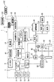
図1に示すように、第1実施形態のシステムは、主に住宅100等の配電盤102を通して供給される系統電源と電気的に接続されて送電される地上側給電設備に含まれる設備側の給電器と、車両1に搭載される車両側充電装置と、非接触で電力を送電する送電コイルからなる地上側給電部111と、非接触で地上側給電部111からの電力を受電する受電コイルからなる車両側受電部11と、を備えて構成されている。
As shown in FIG. 1, the system of the first embodiment is a facility-side power supply included in a ground-side power supply facility that is electrically connected to a system power supply supplied mainly through a
給電器は、整流回路、高周波インバータ等を含む制御回路110、通信機112等から構成され、車両側受電部11に給電する際に動作する。車両側充電装置は、車両1の制御回路10、蓄電装置30、充電器ECU5、通信機12等から構成されている。地上側給電部111は、駐車設備に画成された駐車スペース内に設置または埋設され、所定の通電によって磁界を発生するように構成されている。この地上側給電部111は、駐車スペースへの車両の進入を検知するとともに、車両側に設けられた車両側受電部11との間で非接触による電力の受け渡しを行う。非接触給電システムは、二次電池からなる蓄電装置30と車両の外部の系統電源との間で磁気的に結合された状態、例えば電磁誘導あるいは磁気共鳴によって電力の授受を行う非接触の電力授受システムである。
The power feeder includes a
図2に示すように、第1実施形態は、本発明に係る非接触給電制御装置をパラレルシリーズハイブリッド車に適用した例である。図1に二点鎖線で図示されている内側の部分は、車両1に設けられる構成要素であり、車両制御ECU9または充電器ECU5が制御回路10、蓄電装置ECU3等を介して蓄電装置30への充電を制御する。また、給電器に繋がっているプラグ113に接続される住宅100側のコンセント101には、系統電源(商用電源)等からの電力が供給されるようになっている。
As shown in FIG. 2, 1st Embodiment is an example which applied the non-contact electric power feeding control apparatus which concerns on this invention to a parallel series hybrid vehicle. 1 is a component provided in the
また、コンセント101には、両端にプラグを備えた給電用ケーブルの一端のプラグを接続し、他端のプラグを車両1に設けた受電口に接続することもできる。これによれば、車両1は、非接触給電方式に加え、有線による接触給電方式も実施することが可能な車両である。
Further, the
蓄電装置30は、複数の二次電池からなり、端子電圧を所定の高電圧にする高電圧バッテリであり、昇圧コンバータ31、各インバータ43,44を介して各モータジェネレータ41,42に接続され、蓄電装置ECU3により制御される。蓄電装置30は、発進時、加速時等にモータに電力を供給し、減速時には回生発電した電力を蓄電する。
The
蓄電装置30には、昇圧コンバータ31、降圧コンバータ32、各種補機類からなる負荷33,34(空調用冷凍サイクルの冷媒を駆動する圧縮機等)、制御回路10が接続されている。昇圧コンバータ31は、蓄電装置30の電圧を所定電圧まで(例えばDC288Vを最大650Vまで)昇圧する。この昇圧された電圧は、第1モータジェネレータ41、第2モータジェネレータ42の駆動に用いられ、高出力化と低電力損失の両立が図られる。降圧コンバータ32は、蓄電装置30の電圧を所定電圧まで(例えばDC288Vを12Vまで)降圧して補機バッテリ等の負荷33、ナビゲーション装置等に印加する。
The
第1インバータ43及び第2インバータ44は、昇圧コンバータ31で昇圧された高電圧直流電流を第1モータジェネレータ41、第2モータジェネレータ42へそれぞれ供給するために交流電流に変換する。また、各インバータ43,44は、各モータジェネレータ41,42が発電する交流電流を直流電流に変換する機能も果たす。
The
車両制御ECU9は、エンジンECU2、モータジェネレータECU4、蓄電装置ECU3、充電器ECU5、画像処理ECU6、コーナーセンサECU7、スマートECU8等と通信可能に構成されている。
The vehicle control ECU 9 is configured to be able to communicate with an
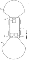
画像処理ECU6は、車両1の周辺の画像を撮像するCCDカメラ等のカメラ61からデータが入力されるようになっている。カメラ61の動作は、画像処理ECU6によって制御される。車載のカメラ61で撮像された画像は、光の明暗を電流の強弱に変換する撮像素子であるCCDに送信され、CCDは、画像を電気信号に変換して画像処理ECU6に入力する。画像処理ECU6は、入力された電気信号を解析することにより画像解析を実施し、その解析結果に基づいて生体の存否を判定する。図3は第1の生体検知手段として用いられる車載のカメラ61の撮影範囲を説明するための車両平面図であり、カメラ61は、図示するように車両1の前方及び後方のそれぞれに撮影範囲D1を有する。なお、カメラ61には、車両1に搭載されているリアビューカメラ、フロントビューカメラ、サイドビューカメラ等を用いることもできる。
Data is input to the image processing ECU 6 from a
この第1の生体検知手段によれば、車載のカメラ61を活用した生体検知により、撮像による直接的かつ効果的な生体検知を可能とし、カメラ61を搭載する車両1に対しては部品点数増加の低減が図れる非接触給電システムを提供できる。
According to the first living body detection means, the living body detection using the in-
コーナーセンサECU7は、車両1のバンパ等の数箇所に埋設されるセンサ71,72,73,74から入力される反射波の電気信号を用いて車両1周辺に生体が存在するか否かを判定する。図7は第2の生体検知手段として用いられるコーナーセンサの検知範囲を説明するための車両平面図であり、各センサ71〜74は、図示するように車両1の周辺にそれぞれ検知範囲D2を有する。各センサ71〜74は、車両1周辺に向けて所定の光または音波を発信する発信部と、その反射波を受信する受信部と、を含む手段であり、例えば超音波を発信及び受信可能な超音波センサで構成することができる。各センサ71〜74の動作は、コーナーセンサECU7によって制御される。
The corner sensor ECU 7 determines whether or not a living body is present around the
つまり、各センサ71〜74は、所定の検知範囲D2に生体が入った場合に、生体からの反射波を受信する。コーナーセンサECU7は、生体が入る前に受信した反射波に対応する電気信号と生体からの反射波に対応する電気信号との違いに基づいて、生体の存否を判定する。
That is, each
この第2の生体検知手段によれば、車両1が有するセンサ71〜74を活用した生体検知により、各センサ71〜74が有する検知範囲に応じた生体検知を可能とし、センサを搭載する車両1に対しては部品点数の増加の低減が図れる非接触給電システムを提供できる。
According to the second living body detection means, the living body detection utilizing the
スマートECU8は、車両1のドア部等の数箇所に埋設される送受信機81から入力される所定の電気信号を用いて車両1周辺に生体が存在するか否かを判定する。図9は第3の生体検知手段として用いられるスマートエントリーの車両側送受信機の検知範囲を説明するための車両平面図であり、各送受信機81は、図示するように車両1の周辺にそれぞれ検知範囲D3を有する。送受信機81が受信する所定の電気信号は、本車両1に固有に設定されたスマートエントリーキーが有する固有管理番号(ID番号ともいう)に対応する電気信号である。
The
つまり、送受信機81は、車両1のユーザーが当該固有管理番号を有するスマートエントリーキーを所持している場合に、ユーザーが所定の検知範囲D3に入ったときに、当該固有管理番号に対応する電気信号を受信する。スマートECU8は、送受信機81によって受信された固有管理番号が本車両1に固有に設定された固有管理番号であるか否かを判定し、一致するときはキー照合がなされたとして当該スマートエントリーキーを所持する者が車両1の周辺に存在すると判定する。スマートECU8は、このようにして生体の存否を判定する。
That is, when the user of the
この第3の生体検知手段によれば、スマートエントリーキーを所持する人がドア等に触れてドアの開錠または施錠の動作をする前に、車両周辺に人が存在することを検知して車両1に人が近づいたことを検出できる。したがって、生体が車両1の傍からある程度離れた状態で電力制限を伴う給電運転を実施することが可能である。また、車両が有する、例えばスマートエントリーキー(携帯送信機)を活用した生体検知により、受信機側の検知範囲に応じた生体検知を可能とし、このような携帯送信機によるドア開閉指令手段を採用する車両1に対しては部品点数増加の低減が図れる非接触給電システムを提供できる。
According to the third living body detection means, the person who has the smart entry key touches the door or the like to detect the presence of a person around the vehicle before unlocking or locking the door. It is possible to detect that a person has approached 1. Therefore, it is possible to carry out a power feeding operation with power limitation in a state where the living body is separated from the side of the
車両制御ECU9は、第4の生体検知手段として、位置検出機能を有する携帯電話機等の携帯機器120が車両1に近づいた場合に、当該機能を用いた携帯機器120の端末位置情報と車両1の位置情報とを照合する。車両制御ECU9は、この位置情報の照合によって、端末位置が車両1周辺の所定の範囲内にあるか否かを判定する。車両制御ECU9は、取得した端末位置が車両1周辺の所定の範囲内にあると判定したときは、位置検出機能を有する携帯機器120を所持する者が車両1の周辺に存在すると判定する。車両制御ECU9は、このようにして生体の存否を判定する。
When the mobile device 120 such as a mobile phone having a position detection function approaches the
なお、車両1の位置検出機能及び携帯機器120の位置検出機能としては、例えば、衛生測位システムであるグローバル・ポジショニング・システム(Global Positioning System)を使用することができる。当該衛生測位システムと車両制御ECU9は、車両位置検出手段及び携帯機器120の端末位置検出手段を構成する。
In addition, as a position detection function of the
この第4の生体検知手段によれば、携帯電話機等の携帯機器120が備える位置検出機能と車両1の位置を検出する位置検出機能とを活用した生体検知により、携帯機器120を所持する人が車両周辺に存在することを検知して、車両1に当該人が近づいたことを検出できる。したがって、生体が車両1の傍からある程度離れた状態で電力制限を伴う給電運転を実施することが可能である。
According to the fourth living body detection means, a person who holds the portable device 120 can detect a living body using the position detection function of the portable device 120 such as a mobile phone and the position detection function of detecting the position of the
車両制御ECU9は、各種センサからの信号によって運転状態に応じたエンジン出力及びモータのトルクを算出し、各ECUに要求値を出力して駆動輪23の駆動力を制御する。エンジンECU2は、車両制御ECU9からのエンジン出力要求に従い、電子スロットルを制御してエンジン20の動力を制御する。モータジェネレータECU4は、車両制御ECU9からの信号により、第1モータジェネレータ41、第2モータジェネレータ42、第1インバータ43、第2インバータ44、及び昇圧コンバータ31を制御する。
The vehicle control ECU 9 calculates engine output and motor torque according to the driving state based on signals from various sensors, and outputs required values to each ECU to control the driving force of the
制御回路10は、整流回路、インバータを含んで構成されており、地上側給電部111を介して外部の系統電源等から得られる交流電力を変換して蓄電装置30に供給する。充電器ECU5は、車両側受電部11への給電要求の有無を判定する手段であり、また蓄電装置30の充放電を制御する電子制御装置である。
The
当該給電要求は、停車中にユーザー等の操作に基づいた蓄電装置30への充電要求や、補機類の駆動要求があり、非接触給電の場合には地上側給電部111に対して車両側受電部11が給電可能な範囲に位置することを充電器ECU5が判断したときに満たされる。有線による接触給電の場合は、給電器側の給電口と車両1の受電口とがプラグ接続等によってケーブルで接続されており、給電実施に必要なその他の条件が成立していると充電器ECU5が判断したときに満たされる。
The power supply request includes a request for charging the
充電器ECU5は、車両制御ECU9、制御回路10を介して各種の負荷33,34等と通信可能に構成され、車両側の通信機12を通じて、地上側給電部111側の制御回路110に設けられた通信機112を介して、給電器側の制御回路110等と通信する。車両側の通信機12は、給電器側の通信機112や、携帯電話機等の携帯機器120と通信可能に構成されている。車両制御ECU9は、充電器ECU5等を介して制御回路10を制御することで、蓄電装置30の充電制御を行い、ナビゲーション装置、エアコン装置、圧縮機等の各種の負荷33,34に対して給電処理も行う。
The charger ECU 5 is configured to be able to communicate with
住宅内の配電盤102は、外部の系統電源等の電力を住宅側で使用される機器の負荷103,104,105等に割り振る機能を果たす。この割り振り機能は、住宅用制御装置100が配電盤102を制御することにより行われる。給電器は、通信機112を介して住宅外部の車両1における通信機12と各種情報を通信することができる。
The
車両1は、遊星歯車機構からなる動力分割機構21を備えている。この動力分割機構21によって第1モータジェネレータ41、第2モータジェネレータ42、及びエンジン20の動力が分割されるようになっている。
The
第1モータジェネレータ41、エンジン20、及び第2モータジェネレータ42は、それぞれ、動力分割機構21のサンギア、キャリア、リングギアに機械的に連結されている。第2モータジェネレータ42には、車軸22を解して駆動輪23が機械的に連結されている。車軸22は、エンジン20及び第2モータジェネレータ42から出力された動力を駆動輪23に伝達するための軸である。また、第1モータジェネレータ41及び第2モータジェネレータ42のそれぞれには、第1インバータ43、第2インバータ44が接続されている。
The
上記構成において、車両1の各部の作動状態について説明する。車両1は蓄電装置30が所定のSOC(state of charge)以下となるまでは蓄電装置30からの電力供給で動作する第2モータジェネレータ42のみで走行する。車両1はその後、発進時、ごく低速時、ゆるやかな下り坂走行時等、エンジン効率のよくない場合には、エンジン20を停止させたまま、蓄電装置30からの電力供給で動作する第2モータジェネレータ42のみで走行する。通常走行時には、エンジン20の動力は2経路に分割し、一方は車軸22を介して駆動輪23を駆動し、もう一方は第1モータジェネレータ41を駆動して発電する。この発電した電力で第1モータジェネレータ41を駆動することにより、エンジン20の駆動力をアシストする。車両制御ECU9は、最大効率が得られるように動力分割機構21の分割の割合を制御する。さらに加速時には、蓄電装置30から電力が供給されて、さらに第2モータジェネレータ42による駆動力が追加される。
The operation state of each part of the
減速時、制動時には、駆動輪23が第2モータジェネレータ42を駆動し、発電機として作動させて回生発電を実施する。この回生した電力は、蓄電装置30に蓄電される。停車時には、冷房時、エンジン暖機中、充電時を除き、エンジン20及びモータジェネレータ41,42は停止している。蓄電装置30への充電が必要な場合の走行時には、通常走行時よりも多めにモータジェネレータ41,42を駆動させて余剰電力を蓄電装置30に充電する。
During deceleration and braking, the
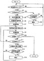
次に、非接触給電制御装置が実施する給電に係る動作について、図4を参照して説明する。図4は、第1実施形態に係るシステムにおいて、車両への充電運転の際に実行する処理手順を示したメインフローチャートである。 Next, operations related to power feeding performed by the non-contact power feeding control device will be described with reference to FIG. FIG. 4 is a main flowchart showing a processing procedure executed in the charging operation of the vehicle in the system according to the first embodiment.
図4に示すように、まずステップ1で、充電のための給電要求があるか否かを判定する。給電要求は、例えば、ユーザー等の操作に基づいた蓄電装置30への充電要求や補機類の駆動要求があると満たされる。
As shown in FIG. 4, first, in
給電要求が満たされたと判定すると、ステップ2で車両1の周辺に生体が検知されたか否かを判定する。この生体検知は、例えば、上記の第1の生体検知〜第4の生体検知のいずれか、または2つ以上を組み合わせて実施することができる。
If it is determined that the power supply request is satisfied, it is determined in
ステップ2で生体が検知されたと判定すると、ステップ5以降の給電運転に移行せずに、次にステップ3で生体の検知後、設定されたα分が経過したか否かを判定する。この設定時間α分は、例えば現在の蓄電装置30のSOCと充電を終了する条件である終了SOCとの差に応じて決定される。設定時間α分は、当該SOCの差が小さいほど長く設定され、大きいほど短く設定される値である。つまり、設定時間α分は、デフォルト値は所定時間、例えば15分に設定されているが、充電運転毎に更新される値である。
If it is determined in
まだ、ステップ3でα分が経過していないと判定した場合はステップ1に戻るが、α分が経過したと判定すると、車両制御ECU9は、車両1の乗員や車両1の周辺に給電が開始できない状況であることを知らせるように報知部13を制御する。報知部13による報知後は、ステップ1に戻る。
If it is determined in step 3 that the α minute has not yet elapsed, the process returns to step 1; however, if it is determined that the α minute has elapsed, the vehicle control ECU 9 starts supplying power to the passengers in the
報知部13は、車両1の乗員や車両1の周辺に対し、音声手段、照明手段、または表示手段によって生体検知情報、給電電力の制限情報を知らせる。音声の場合はホーンやドア開閉時の電子音、照明の場合はヘッドライト、ルームランプ、テールランプ等の点灯やハザード点滅、表示の場合はハンドルの前方またはダッシュボードの中央部に配された計器表示盤の一部に配置される液晶ディスプレイで表示等を実施する。これは、α分経過しても給電が開始できない状態であることを解消し、早期に充電を開始して充電時間を確保するための手段である。このように、車両1が有する音発生手段、照明手段、または表示手段を活用した報知を行うことにより、車両1の乗員や周囲の人に、効果的、早急に電磁界からの影響を受け得る生体を遠ざけるように促すことができる。
The
ステップ2で生体が検知されないと判定すると、給電を開始するための障害となる生体や通信機器の誤作動等の問題が生じていないと判断でき、以降の給電運転に向けての準備を整える。ステップ5で車両1側の給電準備を実施し、ステップ6で給電器側の給電準備を実施する。
If it is determined in
車両1側の給電準備は、車両1側の給電制御用スイッチをONし、システムメインリレーを蓄電装置30側に接続する。さらに、各種ECUへの電源供給のため、降圧コンバータ32を駆動するとともに、充電を終了する条件である終了SOCを所定のマップを用いて算出して設定する。給電器側の給電準備は、給電器側の給電制御用スイッチをONし、システムメインリレーを給電器の二次側に接続する。
For power supply preparation on the
車両1側及び給電器側の給電準備が整うと、ステップ7で給電を開始し、ステップ8で給電指令電力を読み込み、これに応じて給電を制御する(ステップ9)。給電制御後は、蓄電装置30の蓄電量が充電終了SOCの条件が成立するまで給電を継続する。ステップ10で充電終了SOCの条件が成立したと判定すると給電を終了し、本フローチャートは終了する。ステップ10で充電終了SOCの条件がまだ成立していないと判定すると、ステップ11で先のステップ2と同様の生体検知の判定を実施する。ステップ11で生体が検知されていないと判定すると、ステップ9に戻り、給電制御を継続する。
When power supply preparation on the
ステップ11における生体検知判定は、地上側給電部111からの給電中、すなわち、充電運転中に実施される生体検知判定である。この生体検知判定は、充電運転中に生体が検知された場合に、電磁界からの影響を憂慮して給電を制限する処理を実施するためのトリガーとなる。また、この生体検知判定では、後述する第1〜第4の生体検知フローによって生体の有無を判定することができる。 The living body detection determination in step 11 is a living body detection determination performed during power feeding from the ground-side power feeding unit 111, that is, during a charging operation. This living body detection determination serves as a trigger for performing processing for restricting power feeding in consideration of the influence from the electromagnetic field when a living body is detected during the charging operation. In this living body detection determination, the presence or absence of a living body can be determined by first to fourth living body detection flows described later.
ステップ11で生体が検知されたと判定すると、ステップ12で給電指令電力制限を実施する。この給電指令電力制限における電力の制限値は例えば通常の1/2の出力である。この処理により、給電を中断しないで充電終了へ近づくように制御しつつ、生体への悪影響を抑制した給電も実施できるのである。
If it is determined in step 11 that a living body has been detected, power supply command power limitation is performed in
次にステップ13で、給電電力の制限実施後、設定されたβ分が経過したか否かを判定する。この設定時間β分は、先のα分と同様に、現在の蓄電装置30のSOCと充電を終了する条件である終了SOCとの差に応じて決定される。設定時間β分は、当該SOCの差が小さいほど長く設定され、大きいほど短く設定される値である。つまり、設定時間β分は、デフォルト値は所定時間、例えば15分に設定されているが、充電運転毎に更新される値である。
Next, in
まだ、ステップ13でβ分が経過していないと判定した場合はステップ9に戻り、給電制御を継続するが、β分が経過したと判定すると、車両制御ECU9は、車両1の乗員や車両1の周辺に給電を制限している状況であることを知らせるように報知部13を制御する。報知部13による報知後は、再びステップ9に戻り、給電制御を継続する。
If it is determined in
次に、上記のステップ2及びステップ11で実施する生体検知判定の処理について、図5、図8、図10及び図11を参照して説明する。
Next, the biometric detection determination process performed in
(第1の生体検知に係るフロー)
まず、図5を参照して第1の生体検知フローを説明する。この第1の生体検知フローの実行により、車両1の周辺における生体の有無を判定し、その判定結果に対応する以降の適切な処理を実行することができるのである。図5に示すように、ステップ20で、駐車完了状態であるか否かを判定する。このステップ20では、例えば車両1が停車し、車両1の車両側受電部11が地上側給電部111に給電可能な所定範囲内に位置しているか否かを判定する。この判定は駐車完了状態になるまで継続される。
(Flow related to first living body detection)
First, the first living body detection flow will be described with reference to FIG. By executing this first living body detection flow, it is possible to determine the presence or absence of a living body in the vicinity of the
ステップ20で駐車完了状態であると判定すると、次にステップ21で、画像処理ECU6は、車両1に搭載されたカメラ61で撮影した車両周辺の画像を電気信号として取得する。そして、画像処理ECU6は、ステップ22で電気信号として取得した画像データを解析して画像処理を実行し、画像処理の結果を用いて画像データに含まれる撮像範囲で生体が存在するか否かを判定する。
If it is determined in step 20 that the parking is complete, then in step 21, the image processing ECU 6 acquires an image around the vehicle taken by the
ステップ22の判定が「生体の存在なし」の場合は、ステップ24で「生体なし」のフラグを立て、ステップ5やステップ8に進み、本フローを終了する。ステップ22の判定が「生体の存在有り」の場合は、ステップ23で「生体有り」のフラグを立て、ステップ3やステップ12に進み、本フローを終了する。
If the determination in
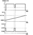
以上の図4を参照して説明した充電運転における、生体検知、給電電力、蓄電装置30のSOCの関係について、図6にしたがって説明する。図6は、充電運転における生体判定の結果に応じた車両1への給電電力の変化とSOCの変化を示したタイムチャートである。
The relationship between the living body detection, the feed power, and the SOC of the
図6に示すように、給電開始時に、生体判定が生体を検知している間は、給電は0[kW]であり、給電を行っていない。そして、生体が検知されなくなると、給電の電力が2[kW]に増加するため、その間の現SOCは終了SOCに向けて順調に増加し続ける。しかし、給電中に、再び生体が検知されると、給電の電力が再び1[kW]に制限されているため、その間のSOCは微増状態に戻る。また生体が検知されなくなると、給電の電力が2[kW]に増加するため、その間の現SOCは終了SOCに向けて順調に増加し続け、終了SOCに達すると、給電が停止し、充電運転を終了する。もちろん、給電の電力制限は1[kW]よりも低い0.5[kW]や、0.5[kW]未満で0[kW]以上の範囲に含まれる所定の値で実施してもよい。 As shown in FIG. 6, while the biometric determination is detecting a living body at the start of power feeding, the power feeding is 0 [kW], and power feeding is not performed. When the living body is no longer detected, the power supplied is increased to 2 [kW], and the current SOC during that time continues to increase smoothly toward the end SOC. However, if a living body is detected again during power feeding, the power supplied is limited to 1 [kW] again, so the SOC during that time returns to a slightly increased state. When the living body is no longer detected, the power supplied to the power supply increases to 2 [kW]. Therefore, the current SOC during that time continues to increase smoothly toward the end SOC, and when the end SOC is reached, the power supply stops and the charging operation is performed. Exit. Of course, the power limitation of the power supply may be performed with a predetermined value included in a range of 0.5 [kW] lower than 1 [kW], or less than 0.5 [kW] and 0 [kW] or more.
(第2の生体検知に係るフロー)
次に、図8を参照して第2の生体検知フローを説明する。この第2の生体検知フローの実行により、車両1の周辺における生体の有無を判定し、その判定結果に対応する以降の適切な処理を実行することができるのである。図8に示すように、ステップ20で、駐車完了状態であるか否かを判定する。このステップ20では、例えば車両1が停車した状態で、車両1の車両側受電部11が地上側給電部111に給電可能な所定範囲内に位置しているか否かを判定する。この判定は駐車完了状態になるまで継続される。
(Flow related to second living body detection)
Next, the second living body detection flow will be described with reference to FIG. By executing this second living body detection flow, it is possible to determine the presence or absence of a living body in the vicinity of the
ステップ20で駐車完了状態であると判定すると、次にステップ21aで、まず、コーナーセンサECU7は、車両1に搭載されたコーナーセンサであるセンサ71〜74によって車両周辺における初期状態の障害物を検出する。これは、初期状態として、車両周辺に壁、フェンス、隣の車両等が存在するかどうかを検出する処理である。
If it is determined in step 20 that the parking is complete, then in step 21a, the corner sensor ECU 7 first detects obstacles in the initial state around the vehicle by means of
そして、コーナーセンサECU7は、ステップ22aで、センサ71〜74による車両周辺の障害物を検出する。このときの検出結果が、先のステップ21aでの初期状態の検出結果と比較して異なる障害物の検出を確認できるものかどうかを判定する。ステップ22aの判定が新たな障害物を検出しないものであるときには、ステップ24で「生体なし」のフラグを立て、ステップ5やステップ8に進み、本フローを終了する。ステップ22aの判定が新たな障害物を検出するものであるときには、ステップ23で「生体有り」のフラグを立て、ステップ3やステップ12に進み、本フローを終了する。
Then, the corner sensor ECU 7 detects obstacles around the vehicle by the
(第3の生体検知に係るフロー)
次に、図10を参照して第3の生体検知フローを説明する。この第3の生体検知フローの実行により、車両1の周辺における生体の有無を判定し、その判定結果に対応する以降の適切な処理を実行することができるのである。図10に示すように、ステップ20a、ステップ22bでは、スマートECU8は、車両1の外に固有管理番号に該当するスマートキーがあるか否かを判定する。ステップ20aでは、スマートキーを所持した者が所定のキー検知範囲D3に入ったか否かを判定することができる。この判定はスマートキーの固有管理番号を受信するまで繰り返される。
(Flow related to third living body detection)
Next, a third living body detection flow will be described with reference to FIG. By executing the third living body detection flow, it is possible to determine the presence or absence of a living body in the vicinity of the
ステップ20aでキー検知範囲D3にキーが存在すると判定すると、次にステップ22bで、検知されたキーの固有管理番号が車両1に登録されている固有管理番号と一致するか否かを判定する。スマートECU8が、ステップ22bで検知されたキーの固有管理番号と車両1の固有管理番号とが一致しないと判定した場合は、ステップ24で「生体なし」のフラグを立て、ステップ5やステップ8に進み、本フローを終了する。スマートECU8が、ステップ22bで車両1の固有管理番号と一致する電気信号を受信したときは、キー照合がなされたとして車両1固有のスマートキーを所持する者が車両1の周辺に存在するとして、ステップ23で「生体有り」のフラグを立て、ステップ3やステップ12に進み、本フローを終了する。
If it is determined in step 20a that a key exists in the key detection range D3, then in step 22b, it is determined whether or not the unique management number of the detected key matches the unique management number registered in the
(第4の生体検知に係るフロー)
次に、図11を参照して第4の生体検知フローを説明する。この第4の生体検知フローの実行により、車両1の周辺における生体の有無を判定し、その判定結果に対応する以降の適切な処理を実行することができるのである。図11に示すように、ステップ20で、駐車完了状態であるか否かを判定する。このステップ20では、例えば車両1が停車した状態で、車両1の車両側受電部11が地上側給電部111に給電可能な所定範囲内に位置しているか否かを判定する。この判定は駐車完了状態になるまで継続される。
(Flow related to fourth living body detection)
Next, a fourth living body detection flow will be described with reference to FIG. By executing this fourth living body detection flow, it is possible to determine the presence or absence of a living body in the vicinity of the
ステップ20で駐車完了状態であると判定すると、車両制御ECU9は、ステップ21c1で車両1の位置情報を取得する。さらに車両制御ECU9は、ステップ21c2で、上述したように車両周辺に携帯機器120が存在する場合にはその正確な位置情報を取得する。そして、車両制御ECU9は、ステップ22cで、取得できた車外の携帯機器120の位置が車両1に対して予め設定された範囲内にあるか否かを判定する。
If it determines with it being a parking completion state by step 20, vehicle control ECU9 will acquire the positional information on the
車両制御ECU9が、ステップ22cで当該携帯機器120の位置が車両1に対する設定範囲内にはないと判定した場合は、携帯機器120を所持する生体が電磁界によって悪影響を受けることはないと判断して、ステップ24で「生体なし」のフラグを立て、ステップ5やステップ8に進み、本フローを終了する。車両制御ECU9が、ステップ22cで当該携帯機器120の位置が当該設定範囲内にあると判定した場合は、携帯機器120を所持する生体が電磁界によって悪影響を受けることおそれがあるため、ステップ23で「生体有り」のフラグを立て、ステップ3やステップ12に進み、本フローを終了する。
If the vehicle control ECU 9 determines in step 22c that the position of the portable device 120 is not within the set range with respect to the
本実施形態の非接触給電制御装置がもたらす作用効果について説明する。非接触給電制御装置は、車両1の外部に設けられる地上側給電部111から車両1に設けられる車両側受電部11へ非接触で電力を送る給電を制御する。非接触給電制御装置は、車両側受電部11への給電運転中に、地上側給電部111の周辺において生体の存在を検知したとき(ステップ11)は、車両側受電部11へ給電する給電電力を、生体の存在が検知されていない場合と比べて制限する(ステップ12)。
The effect which the non-contact electric power feeding control apparatus of this embodiment brings is demonstrated. The non-contact power supply control device controls power supply that transmits power in a non-contact manner from a ground-side power supply unit 111 provided outside the
これによれば、給電運転中に生体を検知した場合は、電磁界による生体への悪影響が生じない程度に給電の電力を制限する給電運転を行って給電を継続することにより、給電を停止することなく、生体への悪影響を抑制しつつ車両1に走行用電力を充電することができる。したがって、車両1への非接触給電を行う際に、生体への悪影響を抑制しつつ車両1への走行用電力を充電することができるため、人体、動物等に対する電磁界の影響の低減及び車両1の充電時間の長期化防止を実現できる。
According to this, when the living body is detected during the power feeding operation, the power feeding is stopped by performing the power feeding operation that limits the power of the power feeding to such an extent that the electromagnetic field does not adversely affect the living body, thereby stopping the power feeding. Therefore, it is possible to charge the
車両が地上側給電部から車両側受電部への給電が可能な位置に停車し、かつ車両側から給電要求があった場合に、例えば、車両のドアの施錠を検出してから給電を開始すると、まだ車両の傍に人がいる可能性があり、電磁界の影響を受けてしまうおそれがある。本実施形態の非接触給電制御装置では、上記の第1の生体検知手段から第4の生体検知手段の少なくとも一つによって生体を検出するため、車両周辺に留まって車両からまだ十分に離れていない人を検出することが可能である。したがって、このような場合に電磁界からの影響の懸念を解消できるのである。 When the vehicle stops at a position where power can be supplied from the ground-side power supply unit to the vehicle-side power reception unit, and when there is a power supply request from the vehicle side, for example, when power supply is started after detecting locking of the door of the vehicle There may still be people near the vehicle and there is a risk of being affected by the electromagnetic field. In the non-contact power supply control device according to the present embodiment, the living body is detected by at least one of the first living body detecting means to the fourth living body detecting means, so that it stays in the vicinity of the vehicle and is not yet sufficiently separated from the vehicle. It is possible to detect people. Therefore, in such a case, the concern about the influence from the electromagnetic field can be solved.
また、給電運転中に、車両のドアの開錠を検出してから給電運転を停止等する場合には、開錠の検出前に、人が車両の傍にいる可能性があり、この場合も電磁界からの影響を受けてしまうおそれがある。本実施形態の非接触給電制御装置では、上記の第1の生体検知手段から第4の生体検知手段の少なくとも一つによって生体を検出するため、ドアの開錠前に車両に近づいている人を検出可能である。したがって、このような場合に電磁界からの影響の懸念を解消できるのである。 Also, when stopping the power feeding operation after detecting the unlocking of the vehicle door during the power feeding operation, there is a possibility that a person is near the vehicle before the unlocking is detected. There is a risk of being affected by electromagnetic fields. In the non-contact power supply control device according to the present embodiment, since the living body is detected by at least one of the first living body detecting means to the fourth living body detecting means, a person approaching the vehicle is detected before the door is unlocked. Is possible. Therefore, in such a case, the concern about the influence from the electromagnetic field can be solved.
非接触給電制御装置は、給電電力を制限した給電運転中に、再び、地上側給電部111の周辺において生体の存在を検知したときは、当該給電電力の制限を継続する(ステップ11、ステップ12)。これによれば、一旦、給電電力の制限を実施して生体への電磁界の影響を抑制する状態を、生体が検知され続けている間は維持する。この制御により、給電運転中に生体が電磁界の影響を受ける可能性がある場合には電力制限を伴う給電を継続できるため、安全性に優れた給電運転を継続的に実施できる。 When the presence of a living body is detected again around the ground-side power feeding unit 111 during the power feeding operation in which the power feeding power is limited, the non-contact power feeding control device continues to limit the power feeding power (steps 11 and 12). ). According to this, the state where the power supply power is once limited to suppress the influence of the electromagnetic field on the living body is maintained while the living body is continuously detected. With this control, when there is a possibility that the living body may be affected by the electromagnetic field during the power feeding operation, the power feeding with the power limitation can be continued. Therefore, the power feeding operation with excellent safety can be continuously performed.
非接触給電制御装置は、給電運転を実施する給電運転要求があり、かつ給電運転を実施する前に、地上側給電部111の周辺において生体の存在を検知したときは、給電運転を開始しない(ステップ2、ステップ3)。これによれば、給電を行っていないときに、例えば給電停止中に生体を検知すると、給電運転要求があった場合でも給電運転を開始しない。これにより、給電運転要求に反しても給電停止状態を維持するため、給電開始と同時に生体が電磁界から影響を受ける可能性を未然に防止するのである。
The non-contact power supply control device does not start the power supply operation when there is a power supply operation request for performing the power supply operation and the presence of a living body is detected around the ground-side power supply unit 111 before the power supply operation is performed (
非接触給電制御装置は、給電電力を制限している時間が設定された時間よりも長くなると、外部に向けて報知する(ステップ4、ステップ14)。これによれば、電力制限の時間が長引いた場合には人に対して報知することにより、生体の接近した状態を早急に解消することができる。このように早急に解消した後は、通常の電力で給電運転を実施することも可能になるので、車両1の蓄電装置30等への充電に要する時間を短くすることができる。したがって、早期の充電完了を実現できる。
The non-contact power supply control device notifies the outside when the time during which the power supply is limited is longer than the set time (steps 4 and 14). According to this, when the time of power limitation is prolonged, a state in which the living body is approaching can be quickly resolved by notifying a person. Since the power supply operation can be performed with normal electric power after it is resolved quickly as described above, the time required for charging the
非接触給電制御装置は、外部に向けて報知するときのトリガーとなる上記の設定された時間(例えば、α分、β分)を、現在の蓄電装置30のSOCと終了SOCとの差に基づいて決定する(ステップ3、ステップ13)。これによれば、現在のSOCと終了SOCとの差の大きさに応じて、外部への報知を開始するまでの時間を短く設定することが可能になり、給電制限を行わない給電運転時間を多く確保することもできる。例えば、現在のSOCと終了SOCとの差が大きい場合は、α分やβ分を短く設定することにより、給電制限を行う給電運転を早期に終了させるために早期に報知を実施し、給電制限のない給電運転時間を多く確保するので、生体への電磁界の影響を抑制し、かつ車両への充電終了を早期に実現する制御を提供することができる。
The non-contact power supply control device determines the set time (for example, α minutes and β minutes) that becomes a trigger when reporting to the outside based on the difference between the SOC of the current
また、本実施形態の非接触給電システムは、上記の非接触給電制御装置と、地上側給電部111の周辺において生体の存在を検知する上記の生体検知手段と、を備える。この構成によれば、給電運転中に、磁界が発生している地上側給電部111の周辺に人体等の生体を検知した場合は、検知していない場合と比較して給電電力を制限する給電運転を実施する非接触給電システムを提供できる。 Further, the non-contact power supply system of the present embodiment includes the above-described non-contact power supply control device and the above-described living body detection unit that detects the presence of a living body in the vicinity of the ground-side power supply unit 111. According to this configuration, when a living body such as a human body is detected in the vicinity of the ground-side power supply unit 111 in which a magnetic field is generated during power supply operation, the power supply restricts the power supply compared to the case where it is not detected. A non-contact power supply system that performs operation can be provided.
(他の実施形態)
以上、本発明の好ましい実施形態について説明したが、本発明は上述した実施形態に何ら制限されることなく、本発明の主旨を逸脱しない範囲において種々変形して実施することが可能である。
(Other embodiments)
The preferred embodiments of the present invention have been described above, but the present invention is not limited to the above-described embodiments, and various modifications can be made without departing from the spirit of the present invention.
上記実施形態では、生体検知手段により車両周辺に生体を検知した場合に、給電の電力を制限する処理を実施する。このとき、電力制限を伴う給電運転を行った後、ユーザー等に報知し、プラグインによるケーブルを介した給電に切り替えるようにしてもよい。また、電力制限を伴う給電運転が長引いて、設定された時間を超過した場合に、プラグインによる給電に切り替えるように、ユーザー等に報知するようにしてもよい。 In the above-described embodiment, when the living body is detected in the vicinity of the vehicle by the living body detection means, the process of limiting the power supply is performed. At this time, after performing a power feeding operation with power limitation, the user may be notified and switched to power feeding via a plug-in cable. In addition, when the power supply operation with power limitation is prolonged and the set time is exceeded, the user or the like may be notified to switch to power supply by plug-in.
上記実施形態では、車両1側の車両制御ECU9が各種ECUとともに統合ECUとして本発明の非接触給電制御装置を構成することと記載しているが、この形態に限定するものではない。例えば、車両制御ECU9が地上側給電設備に設けられる生体検知に関わるECU及び給電制御に関わるECUとともに、統合ECUとして本発明の非接触給電制御装置を構成してもよい。また、地上側給電設備に設けられるECUが地上側給電設備に設けられる生体検知に関わるECU及び給電制御に関わるECUとともに、統合ECUとして本発明の非接触給電制御装置を構成してもよい。また、地上側給電設備に設けられるECUが車両1側に設けられる生体検知に関わるECU及び給電制御に関わるECUとともに、統合ECUとして本発明の非接触給電制御装置を構成してもよい。
In the above-described embodiment, it is described that the vehicle control ECU 9 on the
上記実施形態では、設備側の給電器は、住宅100の系統電源から電力が送電される形態であるが、この形態に限定するものではない。例えば、給電器は、コインパーキング等の駐車設備、商業施設、公共施設等に設けられる充電ステーションに設置されるものであってもよい。
In the above-described embodiment, the facility-side power feeder is configured to transmit power from the system power supply of the
上記実施形態では、本発明に係る車両用電力制御装置をパラレルシリーズハイブリッド車に適用した例を説明したが、当然のことながら本発明が適用可能な車両は、この種のものに限定されない。例えば、電気自動車に適用可能であり、外部から電力を取り込んで、二次電池に蓄電可能な構成を備え、電力を駆動力に変換して走行する車両であれば、適用可能である。 In the above embodiment, the example in which the vehicle power control device according to the present invention is applied to a parallel series hybrid vehicle has been described. However, the vehicle to which the present invention is applicable is not limited to this type. For example, the present invention can be applied to any vehicle that can be applied to an electric vehicle, has a configuration in which electric power is taken in from the outside and can be stored in a secondary battery, and travels by converting electric power into driving force.
上記実施形態では、車両側から延びるコードの先端に設けられるプラグ113が、住宅の配電盤102からのからの配線の端末に設けられるコンセント101に接続されることにより、制御回路10に電力が供給可能な状態になる。このようなプラグ113は住宅側に接続する形態に限定されず、住宅側から延びるコードの先端にあるプラグを車両側の充電リッドに接続する形態であってもよい。
In the above embodiment, the
1…車両
5…充電器ECU(給電要求検出手段)
6…画像処理ECU(生体検知手段)
7…コーナーセンサECU(生体検知手段)
8…スマートECU(生体検知手段)
9…車両制御ECU(非接触給電制御装置、車両位置検出手段)
11…車両側受電部
13…報知部(音発生手段、照明手段)
61…カメラ
71,72,73,74…センサ
81…送受信機(受信機)
111…地上側給電部
112…通信機(携帯送信機)
120…携帯機器
DESCRIPTION OF
6 Image processing ECU (biological detection means)
7. Corner sensor ECU (biological detection means)
8. Smart ECU (Biological detection means)
9 ... Vehicle control ECU (non-contact power supply control device, vehicle position detection means)
DESCRIPTION OF SYMBOLS 11 ... Vehicle side
61 ...
111 ... ground-side
120 ... portable device
Claims (11)
前記車両側受電部への給電運転中に、前記地上側給電部の周辺において生体の存在を検知したときは、前記車両側受電部へ給電する電力を、前記生体の存在が検知されていないときの給電運転と比べて制限することを特徴とする非接触給電制御装置。 Controls the power supply that sends power in a non-contact manner from the ground-side power supply unit (111) provided outside the vehicle (1) that travels using the stored power to the vehicle-side power reception unit (11) provided in the vehicle. A non-contact power supply control device,
When the presence of a living body is detected in the vicinity of the ground-side power feeding unit during the power feeding operation to the vehicle-side power receiving unit, the power to be fed to the vehicle-side power receiving unit is not detected. The non-contact power supply control device is characterized in that it is limited as compared with the power supply operation.
前記地上側給電部の周辺において生体の存在を検知する生体検知手段(6,8,7)と、を備えることを特徴とする非接触給電システム。 The non-contact power supply control device (9) according to any one of claims 1 to 6,
A non-contact power feeding system comprising: living body detecting means (6, 8, 7) for detecting the presence of a living body in the vicinity of the ground side power feeding unit.
Priority Applications (2)
| Application Number | Priority Date | Filing Date | Title |
|---|---|---|---|
| JP2011022058A JP5218576B2 (en) | 2011-02-03 | 2011-02-03 | Non-contact power supply control device and non-contact power supply system |
| US13/359,170 US9184633B2 (en) | 2011-02-03 | 2012-01-26 | Non-contact power supply control device, non-contact power supply system, and non-contact power charge system |
Applications Claiming Priority (1)
| Application Number | Priority Date | Filing Date | Title |
|---|---|---|---|
| JP2011022058A JP5218576B2 (en) | 2011-02-03 | 2011-02-03 | Non-contact power supply control device and non-contact power supply system |
Publications (2)
| Publication Number | Publication Date |
|---|---|
| JP2012165497A true JP2012165497A (en) | 2012-08-30 |
| JP5218576B2 JP5218576B2 (en) | 2013-06-26 |
Family
ID=46844323
Family Applications (1)
| Application Number | Title | Priority Date | Filing Date |
|---|---|---|---|
| JP2011022058A Active JP5218576B2 (en) | 2011-02-03 | 2011-02-03 | Non-contact power supply control device and non-contact power supply system |
Country Status (1)
| Country | Link |
|---|---|
| JP (1) | JP5218576B2 (en) |
Cited By (17)
| Publication number | Priority date | Publication date | Assignee | Title |
|---|---|---|---|---|
| WO2014002634A1 (en) * | 2012-06-27 | 2014-01-03 | ソニー株式会社 | Power supply/reception system, electric mobile body, and power supply/reception method |
| WO2014087589A1 (en) * | 2012-12-06 | 2014-06-12 | 株式会社デンソー | Crosstalk prevention device and control system |
| GB2510125A (en) * | 2013-01-24 | 2014-07-30 | Jaguar Land Rover Ltd | Inductive electric vehicle charging responsive to human or animal detection |
| JP2015089226A (en) * | 2013-10-30 | 2015-05-07 | 株式会社デンソー | Non-contact power supply control system |
| JP2015226424A (en) * | 2014-05-29 | 2015-12-14 | 株式会社Ihi | Non-contact power supply system |
| JP2015231314A (en) * | 2014-06-06 | 2015-12-21 | 日産自動車株式会社 | Mobile-body power feed system and mobile-body power feed method |
| JP2015231315A (en) * | 2014-06-06 | 2015-12-21 | 日産自動車株式会社 | Mobile-body power feed system and mobile-body power feed method |
| JP2016525856A (en) * | 2013-04-22 | 2016-08-25 | ローベルト ボッシュ ゲゼルシャフト ミット ベシュレンクテル ハフツング | Inductive energy transmission device and method for driving inductive energy transmission device |
| JP2016171616A (en) * | 2015-03-11 | 2016-09-23 | 日産自動車株式会社 | System and method for optical power supply for moving body |
| JP2016184860A (en) * | 2015-03-26 | 2016-10-20 | Necプラットフォームズ株式会社 | Wireless communication apparatus, wireless transmission/reception system, and wireless transmission/reception method |
| JP2017139859A (en) * | 2016-02-02 | 2017-08-10 | トヨタ自動車株式会社 | Vehicle and non-contact power transmission system |
| JP2018042434A (en) * | 2016-09-09 | 2018-03-15 | パナソニックIpマネジメント株式会社 | Automatic power feeding device and automatic power feeding system |
| JP2019129541A (en) * | 2018-01-19 | 2019-08-01 | 株式会社デンソー | Power supply device |
| JP2021145449A (en) * | 2020-03-11 | 2021-09-24 | 本田技研工業株式会社 | Contactless charging system |
| JP2021150985A (en) * | 2020-03-16 | 2021-09-27 | 株式会社Lixil | Wireless power feeding system |
| US20230166608A1 (en) * | 2021-11-30 | 2023-06-01 | Ford Global Technologies, Llc | Electrified vehicle wireless charging system |
| JP7468468B2 (en) | 2021-06-23 | 2024-04-16 | トヨタ自動車株式会社 | Power supply device and power supply method |
Citations (10)
| Publication number | Priority date | Publication date | Assignee | Title |
|---|---|---|---|---|
| JP2006021667A (en) * | 2004-07-08 | 2006-01-26 | Mitsubishi Motors Corp | Pseudo-travel sound generator for motor drive vehicle |
| JP2007043773A (en) * | 2005-08-01 | 2007-02-15 | Nissan Motor Co Ltd | Device and method for monitoring/controlling leakes of microwaves |
| JP2007267578A (en) * | 2006-03-30 | 2007-10-11 | Mitsubishi Heavy Ind Ltd | Obstacle detector, energy supply device and system |
| JP2009101927A (en) * | 2007-10-24 | 2009-05-14 | Toyota Motor Corp | Vehicle control device |
| WO2009131990A2 (en) * | 2008-04-21 | 2009-10-29 | Nigel Power Llc | Short range efficient wireless power transfer |
| WO2010006078A1 (en) * | 2008-07-08 | 2010-01-14 | Qualcomm Incorporated | Wireless high power transfer under regulatory constraints |
| JP2010093957A (en) * | 2008-10-08 | 2010-04-22 | Honda Motor Co Ltd | Charging system for vehicle |
| JP2010119246A (en) * | 2008-11-14 | 2010-05-27 | Toyota Motor Corp | Power supply system |
| US20100194206A1 (en) * | 2009-02-05 | 2010-08-05 | Qualcomm Incorporated | Wireless power for charging devices |
| JP2012005226A (en) * | 2010-06-16 | 2012-01-05 | Tokai Rika Co Ltd | Wireless power transmission system |
-
2011
- 2011-02-03 JP JP2011022058A patent/JP5218576B2/en active Active
Patent Citations (10)
| Publication number | Priority date | Publication date | Assignee | Title |
|---|---|---|---|---|
| JP2006021667A (en) * | 2004-07-08 | 2006-01-26 | Mitsubishi Motors Corp | Pseudo-travel sound generator for motor drive vehicle |
| JP2007043773A (en) * | 2005-08-01 | 2007-02-15 | Nissan Motor Co Ltd | Device and method for monitoring/controlling leakes of microwaves |
| JP2007267578A (en) * | 2006-03-30 | 2007-10-11 | Mitsubishi Heavy Ind Ltd | Obstacle detector, energy supply device and system |
| JP2009101927A (en) * | 2007-10-24 | 2009-05-14 | Toyota Motor Corp | Vehicle control device |
| WO2009131990A2 (en) * | 2008-04-21 | 2009-10-29 | Nigel Power Llc | Short range efficient wireless power transfer |
| WO2010006078A1 (en) * | 2008-07-08 | 2010-01-14 | Qualcomm Incorporated | Wireless high power transfer under regulatory constraints |
| JP2010093957A (en) * | 2008-10-08 | 2010-04-22 | Honda Motor Co Ltd | Charging system for vehicle |
| JP2010119246A (en) * | 2008-11-14 | 2010-05-27 | Toyota Motor Corp | Power supply system |
| US20100194206A1 (en) * | 2009-02-05 | 2010-08-05 | Qualcomm Incorporated | Wireless power for charging devices |
| JP2012005226A (en) * | 2010-06-16 | 2012-01-05 | Tokai Rika Co Ltd | Wireless power transmission system |
Cited By (27)
| Publication number | Priority date | Publication date | Assignee | Title |
|---|---|---|---|---|
| WO2014002634A1 (en) * | 2012-06-27 | 2014-01-03 | ソニー株式会社 | Power supply/reception system, electric mobile body, and power supply/reception method |
| WO2014087589A1 (en) * | 2012-12-06 | 2014-06-12 | 株式会社デンソー | Crosstalk prevention device and control system |
| JP2014116999A (en) * | 2012-12-06 | 2014-06-26 | Denso Corp | Crosstalk prevention device |
| GB2510125B (en) * | 2013-01-24 | 2015-07-08 | Jaguar Land Rover Ltd | Vehicle charging method and apparatus |
| GB2510125A (en) * | 2013-01-24 | 2014-07-30 | Jaguar Land Rover Ltd | Inductive electric vehicle charging responsive to human or animal detection |
| JP2016525856A (en) * | 2013-04-22 | 2016-08-25 | ローベルト ボッシュ ゲゼルシャフト ミット ベシュレンクテル ハフツング | Inductive energy transmission device and method for driving inductive energy transmission device |
| JP2015089226A (en) * | 2013-10-30 | 2015-05-07 | 株式会社デンソー | Non-contact power supply control system |
| WO2015064622A1 (en) | 2013-10-30 | 2015-05-07 | 株式会社デンソー | Wireless power supply control system that controls supplying of power according to living body detection |
| US10128681B2 (en) | 2013-10-30 | 2018-11-13 | Denso Corporation | Non-contact power supply control system for controlling power supply by living body detection |
| KR20160068928A (en) | 2013-10-30 | 2016-06-15 | 가부시키가이샤 덴소 | Wireless power supply control system that controls supplying of power according to living body detection |
| JP2015226424A (en) * | 2014-05-29 | 2015-12-14 | 株式会社Ihi | Non-contact power supply system |
| JP2015231314A (en) * | 2014-06-06 | 2015-12-21 | 日産自動車株式会社 | Mobile-body power feed system and mobile-body power feed method |
| JP2015231315A (en) * | 2014-06-06 | 2015-12-21 | 日産自動車株式会社 | Mobile-body power feed system and mobile-body power feed method |
| JP2016171616A (en) * | 2015-03-11 | 2016-09-23 | 日産自動車株式会社 | System and method for optical power supply for moving body |
| JP2016184860A (en) * | 2015-03-26 | 2016-10-20 | Necプラットフォームズ株式会社 | Wireless communication apparatus, wireless transmission/reception system, and wireless transmission/reception method |
| JP2017139859A (en) * | 2016-02-02 | 2017-08-10 | トヨタ自動車株式会社 | Vehicle and non-contact power transmission system |
| JP2018042434A (en) * | 2016-09-09 | 2018-03-15 | パナソニックIpマネジメント株式会社 | Automatic power feeding device and automatic power feeding system |
| US11198369B2 (en) | 2018-01-19 | 2021-12-14 | Denso Corporation | Power supply apparatus |
| JP2019129541A (en) * | 2018-01-19 | 2019-08-01 | 株式会社デンソー | Power supply device |
| JP7010020B2 (en) | 2018-01-19 | 2022-01-26 | 株式会社デンソー | Power supply device |
| JP2021145449A (en) * | 2020-03-11 | 2021-09-24 | 本田技研工業株式会社 | Contactless charging system |
| JP7125442B2 (en) | 2020-03-11 | 2022-08-24 | 本田技研工業株式会社 | Contactless charging system |
| JP2021150985A (en) * | 2020-03-16 | 2021-09-27 | 株式会社Lixil | Wireless power feeding system |
| JP7499585B2 (en) | 2020-03-16 | 2024-06-14 | 株式会社Lixil | Wireless Power Supply System |
| JP7468468B2 (en) | 2021-06-23 | 2024-04-16 | トヨタ自動車株式会社 | Power supply device and power supply method |
| US20230166608A1 (en) * | 2021-11-30 | 2023-06-01 | Ford Global Technologies, Llc | Electrified vehicle wireless charging system |
| US11964576B2 (en) * | 2021-11-30 | 2024-04-23 | Ford Global Technologies, Llc | Electrified vehicle wireless charging system |
Also Published As
| Publication number | Publication date |
|---|---|
| JP5218576B2 (en) | 2013-06-26 |
Similar Documents
| Publication | Publication Date | Title |
|---|---|---|
| JP5218576B2 (en) | Non-contact power supply control device and non-contact power supply system | |
| US10618411B2 (en) | Power feeding system for vehicle, electrically powered vehicle and power feeding apparatus for vehicle | |
| JP5408343B2 (en) | Vehicle parking assist device and electric vehicle including the same | |
| JP5051257B2 (en) | vehicle | |
| JP5010715B2 (en) | Vehicle parking assist device and electric vehicle including the same | |
| JP4868093B2 (en) | Vehicle parking assist device and electric vehicle including the same | |
| JP5263391B2 (en) | Non-contact power receiving apparatus and vehicle equipped with the same | |
| US9263917B2 (en) | Non-contact power receiving apparatus, non-contact power transmitting apparatus, and non-contact power transmitting and receiving system | |
| JP4905571B2 (en) | Vehicle parking assistance device and vehicle equipped with the same | |
| JP5699848B2 (en) | Power supply management device | |
| US20100253139A1 (en) | Method and apparatus for producing tractive effort with interface to other apparatus | |
| JP2010167898A (en) | Hybrid vehicle | |
| CN103552478B (en) | Vehicle electric power system, electric vehicle and vehicle emergency electric supply unit |
Legal Events
| Date | Code | Title | Description |
|---|---|---|---|
| A621 | Written request for application examination |
Free format text: JAPANESE INTERMEDIATE CODE: A621 Effective date: 20120530 |
|
| A977 | Report on retrieval |
Free format text: JAPANESE INTERMEDIATE CODE: A971007 Effective date: 20121115 |
|
| A131 | Notification of reasons for refusal |
Free format text: JAPANESE INTERMEDIATE CODE: A131 Effective date: 20121120 |
|
| A521 | Request for written amendment filed |
Free format text: JAPANESE INTERMEDIATE CODE: A523 Effective date: 20130117 |
|
| TRDD | Decision of grant or rejection written | ||
| A01 | Written decision to grant a patent or to grant a registration (utility model) |
Free format text: JAPANESE INTERMEDIATE CODE: A01 Effective date: 20130205 |
|
| A61 | First payment of annual fees (during grant procedure) |
Free format text: JAPANESE INTERMEDIATE CODE: A61 Effective date: 20130218 |
|
| FPAY | Renewal fee payment (event date is renewal date of database) |
Free format text: PAYMENT UNTIL: 20160315 Year of fee payment: 3 |
|
| R151 | Written notification of patent or utility model registration |
Ref document number: 5218576 Country of ref document: JP Free format text: JAPANESE INTERMEDIATE CODE: R151 |
|
| FPAY | Renewal fee payment (event date is renewal date of database) |
Free format text: PAYMENT UNTIL: 20160315 Year of fee payment: 3 |
|
| R250 | Receipt of annual fees |
Free format text: JAPANESE INTERMEDIATE CODE: R250 |
|
| R250 | Receipt of annual fees |
Free format text: JAPANESE INTERMEDIATE CODE: R250 |
|
| R250 | Receipt of annual fees |
Free format text: JAPANESE INTERMEDIATE CODE: R250 |
|
| R250 | Receipt of annual fees |
Free format text: JAPANESE INTERMEDIATE CODE: R250 |
|
| R250 | Receipt of annual fees |
Free format text: JAPANESE INTERMEDIATE CODE: R250 |
|
| R250 | Receipt of annual fees |
Free format text: JAPANESE INTERMEDIATE CODE: R250 |
|
| R250 | Receipt of annual fees |
Free format text: JAPANESE INTERMEDIATE CODE: R250 |
|
| R250 | Receipt of annual fees |
Free format text: JAPANESE INTERMEDIATE CODE: R250 |
|
| R250 | Receipt of annual fees |
Free format text: JAPANESE INTERMEDIATE CODE: R250 |