JP2012163341A - Hydrogen detection system - Google Patents
Hydrogen detection system Download PDFInfo
- Publication number
- JP2012163341A JP2012163341A JP2011021573A JP2011021573A JP2012163341A JP 2012163341 A JP2012163341 A JP 2012163341A JP 2011021573 A JP2011021573 A JP 2011021573A JP 2011021573 A JP2011021573 A JP 2011021573A JP 2012163341 A JP2012163341 A JP 2012163341A
- Authority
- JP
- Japan
- Prior art keywords
- hydrogen
- dilution
- concentration
- detection system
- gas
- Prior art date
- Legal status (The legal status is an assumption and is not a legal conclusion. Google has not performed a legal analysis and makes no representation as to the accuracy of the status listed.)
- Pending
Links
- 229910052739 hydrogen Inorganic materials 0.000 title claims abstract description 416
- 239000001257 hydrogen Substances 0.000 title claims abstract description 416
- UFHFLCQGNIYNRP-UHFFFAOYSA-N Hydrogen Chemical compound [H][H] UFHFLCQGNIYNRP-UHFFFAOYSA-N 0.000 title claims abstract description 303
- 238000001514 detection method Methods 0.000 title claims abstract description 146
- 150000002431 hydrogen Chemical class 0.000 claims abstract description 114
- 239000012895 dilution Substances 0.000 claims abstract description 112
- 238000010790 dilution Methods 0.000 claims abstract description 112
- 239000007789 gas Substances 0.000 claims abstract description 85
- 230000035945 sensitivity Effects 0.000 claims abstract description 63
- 238000002485 combustion reaction Methods 0.000 claims abstract description 45
- 238000003795 desorption Methods 0.000 claims abstract description 36
- 238000010438 heat treatment Methods 0.000 claims abstract description 33
- 229910052751 metal Inorganic materials 0.000 claims abstract description 17
- 239000002184 metal Substances 0.000 claims abstract description 17
- XUIMIQQOPSSXEZ-UHFFFAOYSA-N Silicon Chemical compound [Si] XUIMIQQOPSSXEZ-UHFFFAOYSA-N 0.000 claims abstract description 12
- 229910052710 silicon Inorganic materials 0.000 claims abstract description 12
- 239000010703 silicon Substances 0.000 claims abstract description 12
- 230000003197 catalytic effect Effects 0.000 claims abstract description 9
- 239000000446 fuel Substances 0.000 claims description 78
- 238000011084 recovery Methods 0.000 claims description 51
- 238000010926 purge Methods 0.000 claims description 33
- 230000007423 decrease Effects 0.000 claims description 15
- 238000007865 diluting Methods 0.000 claims description 15
- 238000012545 processing Methods 0.000 claims description 13
- 238000011144 upstream manufacturing Methods 0.000 claims description 8
- 239000002737 fuel gas Substances 0.000 claims description 7
- 238000007599 discharging Methods 0.000 claims description 5
- 230000008859 change Effects 0.000 claims description 4
- 230000004044 response Effects 0.000 claims description 2
- 238000004140 cleaning Methods 0.000 abstract description 97
- 239000000243 solution Substances 0.000 abstract 1
- 150000003377 silicon compounds Chemical class 0.000 description 17
- BASFCYQUMIYNBI-UHFFFAOYSA-N platinum Substances [Pt] BASFCYQUMIYNBI-UHFFFAOYSA-N 0.000 description 14
- 238000010248 power generation Methods 0.000 description 14
- 230000003584 silencer Effects 0.000 description 11
- 238000000034 method Methods 0.000 description 10
- 230000008569 process Effects 0.000 description 9
- 239000003054 catalyst Substances 0.000 description 8
- VYPSYNLAJGMNEJ-UHFFFAOYSA-N Silicium dioxide Chemical compound O=[Si]=O VYPSYNLAJGMNEJ-UHFFFAOYSA-N 0.000 description 6
- 229910052697 platinum Inorganic materials 0.000 description 6
- 239000000758 substrate Substances 0.000 description 5
- 239000012528 membrane Substances 0.000 description 4
- XLYOFNOQVPJJNP-UHFFFAOYSA-N water Substances O XLYOFNOQVPJJNP-UHFFFAOYSA-N 0.000 description 4
- OKTJSMMVPCPJKN-UHFFFAOYSA-N Carbon Chemical compound [C] OKTJSMMVPCPJKN-UHFFFAOYSA-N 0.000 description 3
- PXHVJJICTQNCMI-UHFFFAOYSA-N Nickel Chemical compound [Ni] PXHVJJICTQNCMI-UHFFFAOYSA-N 0.000 description 3
- KDLHZDBZIXYQEI-UHFFFAOYSA-N Palladium Chemical compound [Pd] KDLHZDBZIXYQEI-UHFFFAOYSA-N 0.000 description 3
- QVGXLLKOCUKJST-UHFFFAOYSA-N atomic oxygen Chemical compound [O] QVGXLLKOCUKJST-UHFFFAOYSA-N 0.000 description 3
- 238000007084 catalytic combustion reaction Methods 0.000 description 3
- 230000008021 deposition Effects 0.000 description 3
- 238000010586 diagram Methods 0.000 description 3
- 238000012986 modification Methods 0.000 description 3
- 230000004048 modification Effects 0.000 description 3
- 239000007800 oxidant agent Substances 0.000 description 3
- 230000001590 oxidative effect Effects 0.000 description 3
- 229910052760 oxygen Inorganic materials 0.000 description 3
- 239000001301 oxygen Substances 0.000 description 3
- 231100000572 poisoning Toxicity 0.000 description 3
- 230000000607 poisoning effect Effects 0.000 description 3
- 238000012360 testing method Methods 0.000 description 3
- 230000000694 effects Effects 0.000 description 2
- 230000005611 electricity Effects 0.000 description 2
- 239000010931 gold Substances 0.000 description 2
- 230000002940 repellent Effects 0.000 description 2
- 239000005871 repellent Substances 0.000 description 2
- 239000010948 rhodium Substances 0.000 description 2
- 239000007787 solid Substances 0.000 description 2
- 239000010409 thin film Substances 0.000 description 2
- 229910018072 Al 2 O 3 Inorganic materials 0.000 description 1
- XEEYBQQBJWHFJM-UHFFFAOYSA-N Iron Chemical compound [Fe] XEEYBQQBJWHFJM-UHFFFAOYSA-N 0.000 description 1
- 229910001260 Pt alloy Inorganic materials 0.000 description 1
- 229910045601 alloy Inorganic materials 0.000 description 1
- 239000000956 alloy Substances 0.000 description 1
- PNEYBMLMFCGWSK-UHFFFAOYSA-N aluminium oxide Inorganic materials [O-2].[O-2].[O-2].[Al+3].[Al+3] PNEYBMLMFCGWSK-UHFFFAOYSA-N 0.000 description 1
- 238000013459 approach Methods 0.000 description 1
- 229910052799 carbon Inorganic materials 0.000 description 1
- 238000005341 cation exchange Methods 0.000 description 1
- 239000011248 coating agent Substances 0.000 description 1
- 238000000576 coating method Methods 0.000 description 1
- 229910017052 cobalt Inorganic materials 0.000 description 1
- 239000010941 cobalt Substances 0.000 description 1
- GUTLYIVDDKVIGB-UHFFFAOYSA-N cobalt atom Chemical compound [Co] GUTLYIVDDKVIGB-UHFFFAOYSA-N 0.000 description 1
- 238000009833 condensation Methods 0.000 description 1
- 230000005494 condensation Effects 0.000 description 1
- 230000003247 decreasing effect Effects 0.000 description 1
- 238000011161 development Methods 0.000 description 1
- 238000003411 electrode reaction Methods 0.000 description 1
- 239000003792 electrolyte Substances 0.000 description 1
- 238000004880 explosion Methods 0.000 description 1
- 239000010408 film Substances 0.000 description 1
- 230000030279 gene silencing Effects 0.000 description 1
- PCHJSUWPFVWCPO-UHFFFAOYSA-N gold Chemical compound [Au] PCHJSUWPFVWCPO-UHFFFAOYSA-N 0.000 description 1
- 229910052737 gold Inorganic materials 0.000 description 1
- 239000007788 liquid Substances 0.000 description 1
- 238000002156 mixing Methods 0.000 description 1
- 229910052759 nickel Inorganic materials 0.000 description 1
- 229910052755 nonmetal Inorganic materials 0.000 description 1
- 229910052763 palladium Inorganic materials 0.000 description 1
- 230000002093 peripheral effect Effects 0.000 description 1
- 229920000642 polymer Polymers 0.000 description 1
- 239000005518 polymer electrolyte Substances 0.000 description 1
- 229920005597 polymer membrane Polymers 0.000 description 1
- 238000006479 redox reaction Methods 0.000 description 1
- 229910052703 rhodium Inorganic materials 0.000 description 1
- MHOVAHRLVXNVSD-UHFFFAOYSA-N rhodium atom Chemical compound [Rh] MHOVAHRLVXNVSD-UHFFFAOYSA-N 0.000 description 1
- 230000000630 rising effect Effects 0.000 description 1
- 229910052707 ruthenium Inorganic materials 0.000 description 1
- 238000001179 sorption measurement Methods 0.000 description 1
- BFKJFAAPBSQJPD-UHFFFAOYSA-N tetrafluoroethene Chemical group FC(F)=C(F)F BFKJFAAPBSQJPD-UHFFFAOYSA-N 0.000 description 1
- 230000008016 vaporization Effects 0.000 description 1
Images


Classifications
-
- G—PHYSICS
- G01—MEASURING; TESTING
- G01N—INVESTIGATING OR ANALYSING MATERIALS BY DETERMINING THEIR CHEMICAL OR PHYSICAL PROPERTIES
- G01N27/00—Investigating or analysing materials by the use of electric, electrochemical, or magnetic means
- G01N27/02—Investigating or analysing materials by the use of electric, electrochemical, or magnetic means by investigating impedance
- G01N27/04—Investigating or analysing materials by the use of electric, electrochemical, or magnetic means by investigating impedance by investigating resistance
- G01N27/14—Investigating or analysing materials by the use of electric, electrochemical, or magnetic means by investigating impedance by investigating resistance of an electrically-heated body in dependence upon change of temperature
- G01N27/16—Investigating or analysing materials by the use of electric, electrochemical, or magnetic means by investigating impedance by investigating resistance of an electrically-heated body in dependence upon change of temperature caused by burning or catalytic oxidation of surrounding material to be tested, e.g. of gas
Abstract
Description
本発明は、水素検出システムに関する。 The present invention relates to a hydrogen detection system.
近年、クリーンなエネルギ源として、水素を燃料ガスとした燃料電池が注目され、この燃料電池を、車両駆動用のエネルギ源として搭載した燃料電池車の開発が進められている。そして、燃料電池車には、水素が漏れた場合に、その漏洩を検知するための水素センサが設けられている。 In recent years, a fuel cell using hydrogen as a fuel gas has attracted attention as a clean energy source, and development of a fuel cell vehicle equipped with this fuel cell as an energy source for driving a vehicle has been promoted. The fuel cell vehicle is provided with a hydrogen sensor for detecting leakage when hydrogen leaks.
水素センサとしては、構造が簡素で小型化が容易な接触燃焼式の水素センサが用いられている。ところが、水素センサは、使用環境の雰囲気中にシリコン化合物の蒸気が存在すると、シリコン化合物が検知素子に付着し、その検出感度が経時的に劣化(シリコン(Si)被毒)することが知られている。 As the hydrogen sensor, a contact combustion type hydrogen sensor having a simple structure and easy to downsize is used. However, in the hydrogen sensor, it is known that when a silicon compound vapor exists in the atmosphere of the usage environment, the silicon compound adheres to the sensing element, and its detection sensitivity deteriorates with time (silicon (Si) poisoning). ing.
そこで、被毒する検知素子をシリコントラップ層で直接に覆う技術が提案されている(特許文献1参照)。 Therefore, a technique has been proposed in which a poisoning detection element is directly covered with a silicon trap layer (see Patent Document 1).
しかしながら、特許文献1では、シリコントラップ層に雰囲気中のシリコン化合物を付着させる一方であるので、シリコン化合物の付着量には限界があると考えられる。このため、検出感度の劣化までの時間を長くできるが、最終的には、検出感度が劣化すると考えられる。
However, in
そこで、本発明は、水素センサの水素検出感度を良好に回復可能な水素検出システムを提供することを課題とする。 Therefore, an object of the present invention is to provide a hydrogen detection system that can satisfactorily recover the hydrogen detection sensitivity of a hydrogen sensor.
前記課題を解決するための手段として、本発明は、水素を燃焼させて燃焼熱を生成する触媒金属から形成され露出した検知素子を有し、燃焼熱に対応して変化する前記検知素子の変化値に基づいて水素濃度を検出する水素センサと、前記検知素子を加熱する加熱手段と、高濃度の水素を貯蔵する水素貯蔵手段と、前記水素貯蔵手段の水素を前記検知素子に案内する水素案内配管と、前記水素案内配管に設けられ、水素の通流を調整する通流調整手段と、前記通流調整手段と前記検知素子との間で、前記水素貯蔵手段からの水素を希釈用ガスで希釈する第1希釈部と、前記加熱手段及び前記通流調整手段を制御する制御手段と、を備え、前記制御手段は、前記水素センサの感度回復要求のある感度回復要求時、前記加熱手段で加熱されている前記検知素子の温度が水素の燃焼熱によって当該検知素子に付着したシリコンの脱離する脱離温度以上になるように、前記通流調整手段によって前記第1希釈部から前記検知素子に向かう水素濃度を制御する感度回復処理を実行することを特徴とする水素検出システムである。 As means for solving the above-mentioned problems, the present invention has a sensing element formed and exposed from a catalytic metal that burns hydrogen to generate combustion heat, and changes in the sensing element that change in response to combustion heat A hydrogen sensor for detecting a hydrogen concentration based on a value; a heating means for heating the sensing element; a hydrogen storage means for storing high-concentration hydrogen; and a hydrogen guide for guiding hydrogen in the hydrogen storage means to the sensing element A diluting gas for supplying hydrogen from the hydrogen storage means between the piping, the flow adjusting means for adjusting the flow of hydrogen, and the flow adjusting means and the sensing element. A first dilution section for dilution, and a control means for controlling the heating means and the flow adjustment means, the control means at the time of the sensitivity recovery request with the sensitivity recovery request of the hydrogen sensor, the heating means Before being heated The flow control means adjusts the hydrogen concentration from the first dilution section to the detection element so that the temperature of the detection element is equal to or higher than the desorption temperature at which silicon adhering to the detection element is desorbed by the combustion heat of hydrogen. A hydrogen detection system characterized by executing a sensitivity recovery process to be controlled.
ここで、「水素を燃焼させて燃焼熱を生成する触媒金属から形成され露出した検知素子」とは、検知素子自体が触媒金属から形成され、水素が検知素子に直接接触し燃焼可能なように、外部に露出していることを意味している。
また、「検知素子に付着したシリコンの脱離する脱離温度以上になるように」とは、後記する実施形態では、検出素子の温度をシリコンの脱離する脱離温度範囲に加熱することを意味する。
Here, “the sensing element formed and exposed from the catalytic metal that generates combustion heat by burning hydrogen” means that the sensing element itself is formed from the catalytic metal so that hydrogen can directly contact the sensing element and combust. , Which means it is exposed to the outside.
In addition, “so as to be equal to or higher than the desorption temperature at which silicon adhering to the detection element is desorbed” means that in the embodiment described later, the temperature of the detection element is heated to a desorption temperature range at which silicon desorbs. means.
このような水素検出システムによれば、制御手段が、水素センサの感度回復要求のある感度回復要求時、加熱手段で加熱されている検知素子の温度が水素の燃焼熱によって検知素子に付着したシリコンの脱離する脱離温度以上になるように、通流調整手段によって第1希釈部から検知素子に向かう水素濃度を制御する感度回復処理を実行する。
このようにして、水素センサの感度回復要求時、検知素子を脱離温度以上に上昇させ、これに付着したシリコンを意図的に脱離し、水素センサ(検知素子)の水素検出感度を回復できる。したがって、水素センサによって長時間に亘って水素濃度を検出可能となる。
According to such a hydrogen detection system, when the control means has a sensitivity recovery request that requires a hydrogen sensor sensitivity recovery, the temperature of the detection element heated by the heating means is attached to the detection element due to the combustion heat of hydrogen. Sensitivity recovery processing for controlling the hydrogen concentration from the first dilution section toward the sensing element is executed by the flow adjusting means so that the temperature is equal to or higher than the desorption temperature at which desorption occurs.
In this way, when the sensitivity recovery request of the hydrogen sensor is requested, the detection element is raised to the desorption temperature or higher, and silicon adhering to the detection element is intentionally desorbed, and the hydrogen detection sensitivity of the hydrogen sensor (detection element) can be recovered. Therefore, the hydrogen concentration can be detected over a long time by the hydrogen sensor.
また、前記水素検出システムにおいて、前記制御手段は、前記加熱手段で前記検知素子を待機温度に加熱し、前記待機温度は、前記脱離温度から、感度回復要求時における水素の燃焼による温度上昇分を差し引いた温度であることが好ましい。 Further, in the hydrogen detection system, the control means heats the sensing element to a standby temperature by the heating means, and the standby temperature is a temperature increase due to hydrogen combustion at the time of a sensitivity recovery request from the desorption temperature. The temperature is preferably obtained by subtracting.
このような水素検出システムによれば、制御手段が、加熱手段で検知素子を待機温度に加熱し、この待機温度は、脱離温度から、感度回復要求時における水素の燃焼による温度上昇分を差し引いた温度に設定される。すなわち、制御手段が、感度回復要求時における水素の燃焼による温度上昇分を考慮して加熱手段で加熱するので、つまり、待機温度を調整するので、言い換えると、第1希釈部による希釈後の水素濃度に対応して待機温度を設定し、この待機温度となるように加熱手段で加熱するので、感度回復要求時において、検知素子の温度が上昇し過ぎることなく、脱離温度を大幅に超えることはない。
また、このようにして待機温度を調整するので、加熱手段の加熱によって消費されるエネルギ(電力等)を小さくできる。
According to such a hydrogen detection system, the control means heats the sensing element to the standby temperature by the heating means, and this standby temperature subtracts the temperature increase due to hydrogen combustion at the time of the sensitivity recovery request from the desorption temperature. Temperature is set. That is, since the control means heats by the heating means in consideration of the temperature rise due to the combustion of hydrogen at the time of sensitivity recovery request, that is, the standby temperature is adjusted, in other words, the hydrogen after dilution by the first dilution unit Since the standby temperature is set according to the concentration and heated by the heating means so that this standby temperature is reached, the temperature of the sensing element does not rise too much when the sensitivity recovery is required, and it greatly exceeds the desorption temperature. There is no.
Moreover, since the standby temperature is adjusted in this way, energy (electric power, etc.) consumed by heating of the heating means can be reduced.
また、前記水素検出システムにおいて、前記水素センサは、前記検知素子に通電する通電手段を備え、水素の燃焼による前記検知素子の抵抗値の上昇に基づいて、水素濃度を検出するセンサであって、前記加熱手段は、前記通電手段を含み、前記検知素子に通電することで、前記検知素子の温度を上昇させることが好ましい。 In the hydrogen detection system, the hydrogen sensor is a sensor that includes energization means for energizing the sensing element, and detects a hydrogen concentration based on an increase in the resistance value of the sensing element due to hydrogen combustion, The heating means preferably includes the energization means, and energizes the sensing element to increase the temperature of the sensing element.
このような水素検出システムによれば、水素センサの備える通電手段を加熱手段として利用できる。これにより、検知素子の加熱専用のヒータ等の加熱手段を別途に備える必要は無く、水素検出システムが簡便な構成となる。 According to such a hydrogen detection system, the energization means provided in the hydrogen sensor can be used as the heating means. Thereby, it is not necessary to separately provide heating means such as a heater dedicated to heating the detection element, and the hydrogen detection system has a simple configuration.
また、前記水素検出システムにおいて、前記通流調整手段は、所定の開状態を維持可能である弁装置を備え、前記制御手段は、前記弁装置の開弁時間/閉弁時間を制御することによって、前記検知素子に向かう水素濃度を制御することが好ましい。 In the hydrogen detection system, the flow adjustment means includes a valve device capable of maintaining a predetermined open state, and the control means controls the valve opening time / valve closing time of the valve device. It is preferable to control the hydrogen concentration toward the sensing element.
このような水素検出システムによれば、制御手段が、所定の開状態を維持可能である簡便な構成の弁装置(通流調整手段)の開弁時間/閉弁時間を制御することによって、検知素子に向かう水素濃度を制御できる。 According to such a hydrogen detection system, the control means detects by controlling the valve opening time / valve closing time of a valve device (flow adjustment means) having a simple configuration capable of maintaining a predetermined open state. The hydrogen concentration toward the device can be controlled.
また、前記水素検出システムにおいて、前記通流調整手段は、所望の開度に調整可能である弁装置を備え、前記制御手段は、前記弁装置の開度の制御することによって、前記検知素子に向かう水素濃度を制御することが好ましい。 Further, in the hydrogen detection system, the flow adjustment means includes a valve device that can be adjusted to a desired opening degree, and the control means controls the opening degree of the valve device to control the detection element. It is preferable to control the hydrogen concentration toward.
このような水素検出システムによれば、制御手段が、所望の開度に調整可能である簡便な構成の弁装置(通流制御手段)の開度を制御することによって、検知素子に向かう水素濃度を制御できる。 According to such a hydrogen detection system, the control means controls the opening degree of a valve device (flow control means) having a simple configuration that can be adjusted to a desired opening degree, whereby the hydrogen concentration toward the sensing element is controlled. Can be controlled.
また、前記水素検出システムにおいて、前記制御手段は、前回の感度回復処理の完了から、前記第1希釈部における水素濃度が所定濃度に低下する第1所定時間の経過以後、今回の感度回復処理を開始することが好ましい。 Further, in the hydrogen detection system, the control means performs the current sensitivity recovery process after a lapse of a first predetermined time after the completion of the previous sensitivity recovery process, when the hydrogen concentration in the first dilution section decreases to a predetermined concentration. It is preferable to start.
このような水素検出システムによれば、制御手段が、前回の感度回復処理の完了から、第1希釈部における水素濃度が所定濃度に低下する第1所定時間の経過以後、今回の感度回復処理を開始する。 According to such a hydrogen detection system, the control means performs the current sensitivity recovery process after the elapse of the first predetermined time when the hydrogen concentration in the first dilution section decreases to the predetermined concentration from the completion of the previous sensitivity recovery process. Start.
すなわち、前回の感度回復処理の完了からしばらくの間、第1希釈部において水素濃度の高い状態が継続し、続けて今回の感度回復処理を開始してしまうと、検知素子に向かう水素濃度が高すぎ、水素の燃焼熱によって検知素子が昇温し過ぎる虞がある。
そこで、このように前回の感度回復処理の完了から、第1希釈部が水素を希釈し、その水素濃度が所定濃度に低下する第1所定時間の経過以後、今回の感度回復処理を開始する。これにより、検知素子に向かう水素濃度が上昇し過ぎることはなく、水素の燃焼熱によって検知素子が予想以上に昇温することはない。
That is, for a while after the completion of the previous sensitivity recovery process, the hydrogen concentration state continues to be high in the first dilution section, and when the current sensitivity recovery process is started, the hydrogen concentration toward the sensing element increases. Therefore, there is a possibility that the temperature of the detection element is excessively increased by the combustion heat of hydrogen.
Thus, the sensitivity recovery process of this time is started after the elapse of the first predetermined time when the first dilution unit dilutes hydrogen and the hydrogen concentration is reduced to the predetermined concentration after the previous sensitivity recovery processing is completed. As a result, the hydrogen concentration toward the sensing element does not increase excessively, and the sensing element does not rise more than expected due to the heat of combustion of hydrogen.
また、前記水素検出システムにおいて、前記制御手段は、前記第1所定時間以上の第2所定時間経過毎に、感度回復処理を繰り返すことが好ましい。 In the hydrogen detection system, it is preferable that the control unit repeats the sensitivity recovery process every second predetermined time that is equal to or longer than the first predetermined time.
このような水素検出システムによれば制御手段が、第1所定時間以上の第2所定時間経過毎に感度回復処理を繰り返すので、水素センサの感度を第2所定時間経過毎に回復できる。
また、第2所定時間は第1所定時間以上であるので、第2所定時間経過毎に感度回復処理を繰り返したとしても、予想よりも高濃度の水素が検知素子に供給されず、水素の燃焼熱によって検知素子が予想以上に昇温することはない。
According to such a hydrogen detection system, the control means repeats the sensitivity recovery process every second predetermined time that is equal to or longer than the first predetermined time, so that the sensitivity of the hydrogen sensor can be recovered every second predetermined time.
Further, since the second predetermined time is equal to or longer than the first predetermined time, even if the sensitivity recovery process is repeated every time the second predetermined time elapses, the hydrogen concentration higher than expected is not supplied to the detection element, and the hydrogen combustion The temperature of the sensing element does not rise more than expected due to heat.
また、前記水素検出システムにおいて、前記第1希釈部に希釈用ガスを通流させる希釈用ガス通流手段(後記する実施形態ではコンプレッサ131)を備え、前記制御手段は、感度回復処理の完了後、前記希釈用ガス通流手段によって希釈用ガスを通流させることが好ましい。
The hydrogen detection system further includes a dilution gas flow means (a
このような水素検出システムによれば、制御手段が、感度回復処理の完了後、希釈用ガス通流手段によって希釈用ガスを通流させるので、第1希釈部における水素濃度を速やかに低下できる。これにより、次回の感度回復処理を迅速に実行することもできる。 According to such a hydrogen detection system, the control means causes the dilution gas flow means to flow the dilution gas after completion of the sensitivity recovery process, so that the hydrogen concentration in the first dilution section can be quickly reduced. As a result, the next sensitivity recovery process can be executed quickly.
また、前記水素検出システムにおいて、前記水素センサは、燃料電池のカソードからのカソードオフガスが通流するカソードオフガス流路に取り付けられ、前記水素案内配管は、前記水素センサよりも上流の前記カソードオフガス流路に合流しており、前記第1希釈部は、前記水素案内配管と前記水素センサとの間の前記カソードオフガス流路であり、希釈用ガスはカソードオフガスであることが好ましい。 In the hydrogen detection system, the hydrogen sensor is attached to a cathode offgas passage through which a cathode offgas from a cathode of the fuel cell flows, and the hydrogen guide pipe is connected to the cathode offgas flow upstream of the hydrogen sensor. Preferably, the first diluting portion is the cathode offgas flow path between the hydrogen guide pipe and the hydrogen sensor, and the diluting gas is a cathode offgas.
このような水素検出システムによれば、燃料電池のカソードからのカソードオフガスを希釈用ガスとして利用するので、希釈用ガスの供給手段を別途に備える必要は無く、システム構成が簡便となり、また、水素検出システムが安価となる。 According to such a hydrogen detection system, since the cathode off-gas from the cathode of the fuel cell is used as the dilution gas, there is no need to separately provide a supply means for the dilution gas, the system configuration is simplified, The detection system is inexpensive.
また、前記水素検出システムにおいて、前記燃料電池のアノードからのアノードオフガスを排出するアノードオフガス流路は、前記水素案内配管よりも上流の前記カソードオフガス流路に合流し、前記アノードオフガス流路にはアノードオフガスを排出する場合に開くパージ弁が設けられており、前記制御手段は、前記パージ弁の閉弁から、前記第1希釈部における水素濃度が所定濃度に低下する第3所定時間の経過以後、感度回復処理を開始することが好ましい。 In the hydrogen detection system, an anode offgas passage for discharging anode offgas from the anode of the fuel cell merges with the cathode offgas passage upstream of the hydrogen guide pipe, and the anode offgas passage includes A purge valve is provided that opens when the anode off-gas is discharged, and the control means is provided after the third predetermined time from when the purge valve is closed until the hydrogen concentration in the first dilution section decreases to a predetermined concentration. It is preferable to start the sensitivity recovery process.
このような水素検出システムによれば、制御手段が、パージ弁の閉弁から、第1希釈部における水素濃度が所定濃度に低下する第3所定時間の経過以後、感度回復処理を開始するので、検知素子に向かう水素濃度が予想以上にならず、水素の燃焼熱によって検知素子が予想以上に昇温することはない。 According to such a hydrogen detection system, the control means starts the sensitivity recovery process after the elapse of the third predetermined time from when the purge valve is closed to when the hydrogen concentration in the first dilution section decreases to the predetermined concentration. The concentration of hydrogen toward the sensing element does not become higher than expected, and the temperature of the sensing element does not rise more than expected due to the combustion heat of hydrogen.
また、前記水素検出システムにおいて、前記水素センサよりも下流の前記カソードオフガス流路に第2希釈部を備えることが好ましい。 In the hydrogen detection system, it is preferable that the cathode offgas flow channel downstream of the hydrogen sensor includes a second dilution unit.
このような水素検出システムによれば、水素センサよりも下流のカソードオフガス流路に第2希釈部を備えるので、感度回復処理の実行時、検知素子に高濃度の水素を供給し、水素の燃焼による温度上昇分を大きくすることもできる。これにより、加熱手段による検知素子の加熱量を小さくでき、加熱手段の加熱によって消費されるエネルギ(電力等)を小さくできる。 According to such a hydrogen detection system, since the cathode offgas flow path downstream of the hydrogen sensor is provided with the second dilution section, high-concentration hydrogen is supplied to the detection element when the sensitivity recovery process is performed, and hydrogen combustion The temperature rise due to can be increased. Thereby, the amount of heating of the detection element by the heating means can be reduced, and the energy (electric power etc.) consumed by the heating means can be reduced.
また、前記水素検出システムにおいて、前記水素センサは、大気に開放された大気開放空間に配置されており、前記第1希釈部は、前記水素案内配管の下流端と前記水素センサとの間において、大気に開放された希釈空間であり、前記希釈用ガスは、大気であることが好ましい。 In the hydrogen detection system, the hydrogen sensor is disposed in an open air space that is open to the atmosphere, and the first diluting unit is between the downstream end of the hydrogen guide pipe and the hydrogen sensor. The dilution space is open to the atmosphere, and the dilution gas is preferably the atmosphere.
このような水素検出システムによれば、第1希釈部が、水素案内配管の下流端と水素センサとの間において、大気に開放された希釈空間であり、希釈用ガスが大気であるので、特別な希釈用ガスの供給手段を備える必要は無く、システム構成が簡便となり、水素検出システムが安価となる。 According to such a hydrogen detection system, the first dilution part is a dilution space opened to the atmosphere between the downstream end of the hydrogen guide pipe and the hydrogen sensor, and the dilution gas is the atmosphere. It is not necessary to provide a diluting gas supply means, the system configuration is simple, and the hydrogen detection system is inexpensive.
また、前記水素検出システムにおいて、燃料電池を有し、前記燃料電池の電力によって走行する燃料電池車に搭載され、前記水素貯蔵装置は、前記燃料電池に燃料ガスとして水素を供給することが好ましい。 The hydrogen detection system preferably includes a fuel cell and is mounted on a fuel cell vehicle that travels using electric power of the fuel cell, and the hydrogen storage device supplies hydrogen as a fuel gas to the fuel cell.
このような水素検出システムによれば、水素センサの耐久性が向上する。
また、水素貯蔵装置は燃料電池に燃料ガスとして水素を供給するので、言い換えると、燃料電池車に搭載された水素タンクを、感度回復処理用の高濃度の水素が貯蔵された水素貯蔵手段とするので、燃料電池車単体でも適宜に感度回復処理を実行できる。
According to such a hydrogen detection system, the durability of the hydrogen sensor is improved.
In addition, the hydrogen storage device supplies hydrogen as fuel gas to the fuel cell. In other words, the hydrogen tank mounted on the fuel cell vehicle is used as a hydrogen storage means for storing high-concentration hydrogen for sensitivity recovery processing. Therefore, the sensitivity recovery process can be appropriately executed even with a single fuel cell vehicle.
本発明によれば、水素センサの水素検出感度を良好に回復可能な水素検出システムを提供することができる。 According to the present invention, it is possible to provide a hydrogen detection system that can satisfactorily recover the hydrogen detection sensitivity of a hydrogen sensor.
以下、本発明の一実施形態について、図1〜図13を参照して説明する。 Hereinafter, an embodiment of the present invention will be described with reference to FIGS.
≪燃料電池車の構成≫
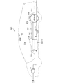
図1に示す燃料電池車200は、PEFC(Polymer Electrolyte Fuel Cell)型の燃料電池スタック110、水素タンク121(水素貯蔵手段)、水素センサ10A〜10Dを含む燃料電池システム100を備えており、燃料電池スタック110の発電電力によって駆動モータ(図示しない)を回転させて走行する。
≪Configuration of fuel cell vehicle≫
A
燃料電池スタック110はセンタートンネル201内に配置されており、水素タンク121はタンク室202内に配置されている。センタートンネル201は、フロアパネル203の車幅方向の中央部分が上方に隆起することで形成され、前後方向に延びる細長の空間である。タンク室202は、フロアパネル203の後側部分が水素タンク121の外形に対応して隆起することで形成され、車幅方向に延びる円柱状の空間である。
The
水素センサ10Aは、後記するように配管132a(カソードオフガス流路)に取り付けられており、カソードオフガス中の水素濃度を検出し、ECU150に出力するようになっている(図2参照)。
As will be described later, the
水素センサ10Bは、燃料電池スタック110上方のフロアパネル203の下面に取り付けられており、燃料電池スタック110等から漏洩し、センタートンネル201に滞留する水素濃度を検出し、ECU150に出力するようになっている(図2参照)。
水素センサ10Cは、水素タンク121の上方のフロアパネル203の下面に取り付けられており、水素タンク121等から漏洩し、タンク室202に滞留する水素濃度を検出し、ECU150に出力するようになっている(図2参照)。
水素センサ10Dは、車室204の上方の天井205に取り付けられており、車室204に滞留する水素濃度を検出し、ECU150に出力するようになっている(図2参照)。
すなわち、水素センサ10B〜10Dは、センタートンネル201、タンク室202、車室204等の大気に開放された大気開放空間に配置されている。
The
The
The
That is, the hydrogen sensors 10 </ b> B to 10 </ b> D are disposed in an open atmosphere that is open to the atmosphere, such as the
≪燃料電池システム≫
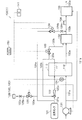
燃料電池システム100は、図2に示すように、水素検出システム1が組み込まれたシステムであって、燃料電池スタック110(燃料電池)と、燃料電池スタック110のアノードに対して水素(燃料ガス)を給排するアノード系と、燃料電池スタック110のカソードに対して空気(酸化剤ガス)を給排するカソード系と、水素センサ10A〜10Dと、これらを電子制御するECU150(Electronic Control Unit、制御手段)と、を備えている。
≪Fuel cell system≫
As shown in FIG. 2, the
<燃料電池スタック>
燃料電池スタック110は、複数(例えば200〜400枚)の固体高分子型の単セルが積層して構成されたスタックであり、複数の単セルは直列で接続されている。単セルは、MEA(Membrane Electrode Assembly:膜電極接合体)と、これを挟む2枚の導電性を有するセパレータと、を備えている。MEAは、1価の陽イオン交換膜等からなる電解質膜(固体高分子膜)と、これを挟むアノード及びカソード(電極)と、を備えている。
<Fuel cell stack>
The
アノード及びカソードは、カーボンペーパ等の導電性を有する多孔質体と、これに担持され、アノード及びカソードにおける電極反応を生じさせるための触媒(Pt、Ru等)と、を含んでいる。 The anode and the cathode include a porous body having conductivity such as carbon paper, and a catalyst (Pt, Ru, etc.) supported on the anode and causing an electrode reaction in the anode and the cathode.
各セパレータには、各MEAの全面に水素又は空気を供給するための溝や、全単セルに水素又は空気を給排するための貫通孔が形成されており、これら溝及び貫通孔がアノード流路111(燃料ガス流路)、カソード流路112(酸化剤ガス流路)として機能している。 Each separator is formed with a groove for supplying hydrogen or air to the entire surface of each MEA, and through holes for supplying and discharging hydrogen or air to all single cells. It functions as a channel 111 (fuel gas channel) and a cathode channel 112 (oxidant gas channel).
<アノード系>
アノード系は、水素タンク121(水素貯蔵手段)と、エゼクタ122と、常閉型のパージ弁123と、水素センサ10A、10B(10C、10D)のクリーニング時(感度回復処理の実行時)に開かれる常閉型のクリーニング弁124、125(通流調整手段)と、を備えている。
<Anode system>
The anode system is opened when the hydrogen tank 121 (hydrogen storage means), the
水素タンク121は、高濃度(高純度)の水素を高圧(例えば30〜70MPa)で貯蔵するタンクである。そして、水素タンク121の水素は、配管121a、エゼクタ122、配管122aを通って、アノード流路111に供給されるようになっている。エゼクタ122は、水素タンク121からの水素によって負圧を発生させると共に、この負圧によって後記する水素を含むアノードオフガスを吸引し、水素を循環させる装置(真空ポンプ)である。
The
なお、配管121aには、下流に向かって、図示しない常閉型の遮断弁と減圧弁(レギュレータ)とが設けられている。遮断弁は、燃料電池システム100(燃料電池車200)の起動中(IG141のON中)、ECU150によって開かれる。また、減圧弁は、水素タンク121からの水素の圧力を適宜に減圧する。
The
アノード流路111から排出された未反応の水素を含むアノードオフガスは、配管122b(水素循環ライン)を通ってエゼクタ122の吸気口に向かうようになっている。
The anode off gas containing unreacted hydrogen discharged from the
配管122bは、配管123a、パージ弁123、配管123bを介して、後記する希釈ボックス132に接続されている。そして、パージ弁123が、ECU150によって所定の開弁時間にて開かれると、未反応の水素を含むアノードオフガスが、希釈ボックス132に排出され、燃料電池スタック110の発電性能が回復するようになっている。
The
なお、ECU150は、例えば、燃料電池スタック110を構成する単セルの電圧のうちの最低の電圧(最低セル電圧)が、所定単セル電圧以下である場合、パージ弁123を開く必要があると判断するように設定されている。また、ECU150は、セル電圧モニタ(図示しない)を介して、複数の単セルの電圧を監視している。
The
クリーニング弁124、125については、後で説明する。
The cleaning
<カソード系>
カソード系は、コンプレッサ131(酸化剤ガス供給手段)と、希釈ボックス132と、サイレンサ133(消音器、第2希釈部)と、流量センサ134と、を備えている。
コンプレッサ131は、ECU150の指令に従って作動すると、酸素を含む空気を吸気し、配管131aを介して、カソード流路112に向けて圧送するようになっている。また、コンプレッサ131は、後記する第1希釈部D1において、水素を希釈するカソードオフガス(希釈用ガス)を通流させる希釈用ガス通流手段としても機能している。
<Cathode system>
The cathode system includes a compressor 131 (oxidant gas supply means), a
When the
配管131aは、配管131bを介して、サイレンサ133(第2希釈部)に接続され、コンプレッサ131の吐出した空気の一部が、配管131bを通って常時に供給されるようになっている。これにより、水素センサ10Aのクリーニング時、サイレンサ133において、配管131bからの空気(希釈用ガス)が、水素センサ10Aからの水素を希釈するようになっている。したがって、クリーニング時においてクリーニング用の水素を高濃度で水素センサ10Aに供給し、水素の燃焼熱によって後記する検知素子21(図4参照)を大幅に昇温することも可能となる。よって、検知素子21の待機温度を下げることも可能となる。
なお、配管131bに常閉型の電磁弁(通流調整手段)を設けて、水素センサ10Aのクリーニング時に開く構成としてもよい。
The
In addition, it is good also as a structure which provides a normally closed solenoid valve (flow adjustment means) in the
カソード流路112から排出されたカソードオフガス(希釈用ガス)は、配管132a、希釈ボックス132、配管132b、サイレンサ133、配管133a(テールパイプ)を通って、車外(外部)に排気されるようになっている。
The cathode off-gas (dilution gas) discharged from the
希釈ボックス132は、開弁したパージ弁123からのアノードオフガスとカソードオフガスとを混合し、アノードオフガスに含まれる水素を希釈するボックスであり、その内部に混合用(希釈用)の希釈空間を有している。したがって、パージ弁123が開かれた後の所定時間において、希釈ボックス132からのカソードオフガス(希釈用ガス)における水素濃度はやや上昇することになる(図12参照)。
The
<サイレンサ>
サイレンサ133は、カソード系を通流する空気(カソードオフガスを含む)を伝播するコンプレッサ131の作動音を低減する消音器であり、その内部に消音空間(チャンバ)を有している。
<Silencer>
The
ここで、サイレンサ133は、水素センサ10Aよりも下流に配置されており、そして、このような消音空間を有するので、水素センサ10Aからの水素を希釈する第2希釈部としても機能している。これにより、水素センサ10Aのクリーニング時、その検知素子21(図4参照)に、高濃度の水素を供給し、水素の燃焼による温度上昇分を大きくすることも可能となっている。その結果、通電による検知素子21の加熱量(通電量)を小さくすることも可能となっている。
Here, the
流量センサ134は、配管131aに取り付けられており、カソード流路112に向かう空気の流量を検出し、ECU150に出力するようになっている。
ここで、カソード流路112に向かう空気の流量と、カソード流路12から排出され、後記する第1希釈部D1(図3参照)に向かう、カソードオフガス(希釈用ガス)の流量とは、比例関係であるから、ECU150は、流量センサ134からの空気の流量に基づいて、第1希釈部D1に向かう、カソードオフガスの流量を推定(算出)するようになっている。
The
Here, the flow rate of the air toward the
<水素センサ>
次に、水素センサ10Aの構成について、図3〜図5を参照して説明する。なお、水素センサ10B〜10Dは、水素センサ10Aと同様であるので、説明を省略する。
<Hydrogen sensor>
Next, the configuration of the
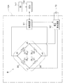
水素センサ10Aは、配管132bを通流するガス中の水素濃度を検出する接触燃焼式のセンサであり、ブリッジ回路Bと、制御回路51と、電圧発生回路52と、を備えている。ブリッジ回路Bの一部、制御回路51、及び、電圧発生回路52は、後記する基板61上に形成された回路パターン及びこれに設けられた電子部品によって構成されている。
The
また、水素センサ10Aは、基板61と、基板61を収容する薄箱状のケース62と、ケース62の底壁部から鉛直下向きに延びるように形成された有底円筒状のハウジング63と、を備えている。
The
ケース62は、配管132bの天壁部にボルト(図示しない)によって取り付けられている。
ハウジング63は、配管132bの天壁部に形成された貫通孔に差し込まれている。そして、ハウジング63の底壁部に形成されたガス出入口63aを介して、水素、シリコン化合物を含むガスが、配管132bと、ハウジング63内のガス検出室63bとの間で、出入するようになっている。
The
The
ガス出入口63aに蓋をするように、撥水フィルタ64及び防爆フィルタ65が設けられている。撥水フィルタ64は、ガス(水素)の通過を許容するが、液体(水滴)の通過を許容しないフィルタであり、例えば、テトラフルオロエチレン膜から構成される。防爆フィルタ65は、防爆性を確保するためのフィルタであり、例えば、金属製のメッシュや多孔質体から構成される。この他、活性炭等を有しシリコン化合物を吸着する吸着フィルタや、ガス検出室63bの結露水を気化し除去するためのヒータを備える構成としてもよい。
A
<水素センサ−ブリッジ回路>
ブリッジ回路Bは、第1辺20と、第2辺30と、を備えており、第1辺20と第2辺30とは、電圧発生回路52に対して並列に接続されている。
<Hydrogen sensor bridge circuit>
The bridge circuit B includes a
第1辺20は、検知素子21と補償素子22(温度補償素子)とを備え、検知素子21と補償素子22とが直列に接続されることで構成されている。
検知素子21は、基板61から鉛直下方に延びると共に第1辺20の一部を構成する金属製のステー21a、21aに固定され、ガス検出室63b配置されており、ガス検出室63bに露出している。これと同様に、補償素子22は、ステー22a、22aに固定され、ガス検出室63bに配置されており、ガス検出室63bに露出している。
したがって、検知素子21の抵抗値R21、補償素子22の抵抗値R22は、ガス検出室63bの温度(環境温度、雰囲気温度)に基づいて変化することになる。
The
The
Accordingly, the resistance value R 21 of the
検知素子21は、水素を触媒燃焼させる白金(Pt)や白金合金等の触媒金属から形成されており、白金(Pt)等の担持された触媒担体(触媒層)をその周面に備えていない。本実施形態に係る検知素子21は、この触媒金属から成る線材を、コイル状に成形することで構成され、その表面は平滑な金属表面である。そして、この表面は触媒金属表面を構成し、この平滑な触媒金属表面(検知素子21の表面)に水素が直接接触するようになっている。なお、検知素子21がコイル状であることにより、水素の燃焼熱が放熱し難くなり、検知素子21の温度が容易に上昇するようになっている。また、触媒金属としては、白金(Pt)の他に、パラジウム(Pd)、ロジウム(Rh)、鉄(Fe)、コバルト(Co)、ニッケル(Ni)や、これらの合金も使用できる。
The
このように検知素子21は、触媒活性を有しており、検知素子21自体に直接接触する水素と酸素とを触媒燃焼反応(酸化還元反応)させるようになっている。そして、水素が触媒燃焼反応すると、その燃焼熱によって検知素子21の温度が、上昇するようになっている。
したがって、検知素子21の温度、抵抗値R21は、ガス検出室63bの温度と水素の燃焼熱とに基づいて、変化することになる。
Thus, the
Accordingly, the temperature of the
補償素子22は、触媒金属から成る線材をコイル状に成形したものの表面を、水素に対して不活性である不活性層でコーティングしたものである。不活性層は、アルミナ(Al2O3)やシリカ(SiO2)等の非金属や、金(Au)等の水素と反応しない金属から形成される。これにより、補償素子22に水素が接触しても、水素は触媒燃焼反応せず、燃焼熱は生成しない。
したがって、補償素子22の温度、抵抗値R22は、ガス検出室63bの温度(環境温度、雰囲気温度)のみに基づいて変化することになる。
The
Accordingly, the temperature of the compensating
第2辺30は、第1抵抗素子31(抵抗値R31)と第2抵抗素子32(抵抗値R32)とを備え、第1抵抗素子31と第2抵抗素子32とが直列に接続されることで構成されている。第1抵抗素子31及び第2抵抗素子32は、基板61上に設けられている。なお、第1抵抗素子31の抵抗値R21、第2抵抗素子32の抵抗値R22は、既知であり、固定値である。
The
第1辺20の両端と、第2辺30の両端とは、それぞれ接続されて、入力端子J1、入力端子J2を構成している。入力端子J1、入力端子J2は、電圧発生回路52に接続されており、電圧発生回路52で発生した電圧VINが入力端子J1、J2(ブリッジ回路B)に印加するようになっている。そして、このように電圧発生回路52で発生した電圧VINが印加すると、検知素子21に通電し、検知素子21の温度が上昇するようになっている。
すなわち、本実施形態において、検知素子21に通電し検知素子21を加熱手段(通電手段)は、電圧発生回路52と、後記する外部電源70と、を備えて構成されている。
Both ends of the
That is, in the present embodiment, a means for energizing the
第1辺20において、検知素子21と補償素子22との間の第1中間点は、出力端子J3を構成し、第2辺30において、第1抵抗素子31と第2抵抗素子32との間の第2中間点は出力端子J4を構成している。出力端子J3、出力端子J4は、制御回路51に接続されており、ブリッジ回路Bの電圧VOUT(出力)が、出力端子J3、J4を介して、制御回路51に出力されるようになっている。
On the
そして、水素が検知素子21に接触し、水素の燃焼熱によって、検知素子21の抵抗値R21(変化値)が変化し、検知素子21の抵抗値R21が補償素子22の抵抗値R22よりも大きくなると、出力端子J3の電位が出力端子J4の電位よりも高くなり、水素濃度に対応した電圧VOUTが制御回路51に出力され、水素濃度が検知されるようになっている。
なお、水素が検知素子21に接触しておらず、水素の燃焼熱が生成していない場合、検知素子21の抵抗値R21と補償素子22の抵抗値R22とは等しく、そして、出力端子J3の電位と出力端子J4の電位とは等しくなり、電圧VOUTは0となる。
Then, hydrogen is brought into contact with the
The hydrogen is not in contact with the
<水素センサ−制御回路等>
制御回路51は、CPU、ROM、RAM、各種インタフェイス、電子回路等を含んで構成されている。そして、制御回路51は、ECU150からの指令と、その内部に記憶されたプログラムに従って、水素センサ10Aを適宜に制御するようになっている。
すなわち、制御回路51は、ECU150からの指令に従って、電圧発生回路52を作動させ、そして、ブリッジ回路Bからの電圧VOUTに基づいて水素濃度を算出し、水素濃度に対応した信号をECU150に出力するようになっている。
ただし、この構成に限定されず、その他に例えば、ECU150が電圧発生回路52を直接制御し、ブリッジ回路Bの電圧VOUTがECU150に直接出力される構成でもよい。
<Hydrogen sensor-control circuit, etc.>
The
That is, the
However, the present invention is not limited to this configuration. For example, the
電圧発生回路52は、DC−DCコンバータ等を備えて構成され、外部電源70(例えば12Vバッテリ)と接続されている。そして、電圧発生回路52は、制御回路51からの指令に従って作動し、ブリッジ回路Bに所定電圧を印加するようになっている。
The
<水素センサ−シリコン化合物の付着量>
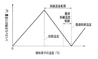
ここで、本願発明者等は、図6に示すように、シリコンの雰囲気下において、白金等の触媒金属から形成された検知素子21の温度が高くなるにつれて、検知素子21へのシリコン化合物の付着量(シリコン被毒量、(g))が増加するものの、所定の脱離温度範囲では、シリコン化合物の付着量が減少するという知見を得た。
<Hydrogen sensor-silicon compound adhesion amount>
Here, as shown in FIG. 6, the inventors of the present application attach the silicon compound to the
これは、脱離温度範囲では、検知素子21に付着しているシリコン化合物が、検知素子21から脱離しているためと考えられる。すなわち、脱離温度範囲では、シリコン化合物の付着速度に対して、脱離速度が小さいながらも略同オーダー程度になっており、そして、最適脱離温度において脱離速度は付着速度に略等しくなり、最適脱離温度を越えると再び脱離速度よりも付着速度が大きくなる、という知見を得た。
This is presumably because the silicon compound adhering to the
また、脱離温度範囲では、検知素子21の温度が高くなるにつれて、シリコン化合物の付着量(g)が減少し、最適脱離温度で付着量が最小になるという傾向を得た。すなわち、水素センサ10Aの水素の検出感度を回復させるには、検知素子21を、脱離温度範囲、好ましくは前記最適脱離温度を含む最適脱離温度範囲(例えば、「最適脱離温度−10℃」〜「最適脱離温度」の範囲)に昇温させる、いう知見を得た。
Further, in the desorption temperature range, as the temperature of the
このような知見に基づいて、本実施形態では、水素センサ10Aのクリーニング時に検知素子21を最適脱離温度範囲に昇温させるために、検知素子21への通電による発熱と、検知素子21への水素の接触燃焼による燃焼熱と、を利用している(図7参照)。
Based on such knowledge, in the present embodiment, in order to raise the temperature of the
すなわち、図7に示すように、クリーニング時(感度回復処理の実行時)、及び、非クリーニング時(感度回復処理の非実行時、待機時)に、第1希釈部D1からの水素濃度を考慮したうえで、検知素子21への通電によって、検知素子21を常温から待機温度に加熱(昇温)し、クリーニング時に水素の燃焼熱によって、最適脱離温度範囲にさらに昇温させている。そして、本実施形態において、待機温度は最適脱離温度から水素の燃焼による温度上昇分を差し引いた温度に設定されている。
That is, as shown in FIG. 7, the hydrogen concentration from the first dilution part D1 is taken into account during cleaning (when the sensitivity recovery process is performed) and during non-cleaning (when the sensitivity recovery process is not performed and during standby). In addition, the
<クリーニング弁>
次に、図2、図3、図8を参照して、クリーニング弁124、125周りの構成を説明する。
<Cleaning valve>
Next, the configuration around the cleaning
<水素センサ10A用のクリーニング弁>
前記減圧弁の下流の配管121aは、配管124a、クリーニング弁124、配管124bを介して、後記するように水素センサ10Aの上流の配管132bに接続されている。そして、水素センサ10Aのクリーニング時(感度回復処理の実行時)、ECU150によってクリーニング弁124が開かれると、水素タンク121の高濃度の水素が、配管121a、配管124a、配管124bを通って、水素センサ10Aに向かうようになっている。
<Cleaning valve for
A
すなわち、本実施形態において、水素タンク121の水素を水素センサ10Aの検知素子21に案内する水素案内配管は、配管124aと配管124bとを備えて構成されている。そして、この水素案内配管にクリーニング弁124(通流調整手段)が設けられている。
That is, in this embodiment, the hydrogen guide pipe for guiding the hydrogen in the
配管124bには、オリフィス124cが設けられており、配管124bから配管132bに流入する水素の流量が絞られている。これにより、クリーニング弁124を開閉制御することによって、配管123bに流入し、後記する第1希釈部D1で希釈後、水素センサ10Aに向かう水素濃度が容易に制御されるようになっている。
ただし、オリフィス124cは、クリーニング弁124の下流に限定されず、クリーニング弁124の上流でもよく、また、オリフィス124cを備えない構成でもよい。
An
However, the
また、配管124aは、水素センサ10Aよりも上流の配管132b(カソードオフガス流路)に合流している。そして、配管124bの合流点と水素センサ10Aとの間の配管132b(カソードオフガス流路)は、クリーニング弁124からの水素をカソードオフガス(希釈用ガス)で希釈する第1希釈部D1として機能している(図3参照)。なお、第1希釈部D1は、クリーニング弁124と水素センサ10Aとの間に配置されている。
Further, the
クリーニング弁124は、ソレノイドによって駆動する常閉型の電磁弁(弁装置)であって、例えばゲート弁によって構成され、ECU150から開弁指令が入力されている間、所定の開状態(開度)を維持するようになっている。
そして、ECU150が、クリーニング弁124の開弁時間/閉弁時間を例えばPWM制御することによって、クリーニング弁124を通って、配管132b(第1希釈部D1)に向かう水素(高濃度の水素)の流量が容易に制御され、その結果、水素センサ10Aの検知素子21に向かう水素濃度が制御されるようになっている。
The cleaning
Then, the
<水素センサ10B(10C、10D)用のクリーニング弁>
配管124aの途中は、配管125a、常閉型のクリーニング弁125、配管125bが順に接続されている。配管125bの下流端は、配管125bからの水素が水素センサ10B(10C、10D)に向かうように配置されている。すなわち、水素センサ10B〜10D毎に、配管125a、クリーニング弁125、配管125bが設けられているが、図2では省略している。
<Cleaning valve for
In the middle of the
そして、水素センサ10B(10C、10D)のクリーニング時(感度回復処理の実行時)、ECU150によってクリーニング弁125が開かれると、水素タンク121の高濃度の水素が、配管121a、配管124a、配管125a、配管125bを通って、水素センサ10B(10C、10D)に向かうようになっている。
When the
すなわち、本実施形態において、水素タンク121の水素を水素センサ10B(10C、10D)の検知素子21に案内する水素案内配管は、配管124aの一部と、配管125aと、配管125bとを備えて構成されている。そして、この水素案内配管にクリーニング弁125(通流調整手段)が設けられている。
That is, in this embodiment, the hydrogen guide pipe for guiding the hydrogen in the
配管125bには、オリフィス125cが設けられており、配管125bから後記する第1希釈部D2(図8参照)に向かう水素の流量が絞られている。これにより、クリーニング弁125を開閉制御することによって、第1希釈部D2で希釈後、水素センサ10Bに向かう水素濃度が容易に制御されるようになっている。
ただし、オリフィス125cは、クリーニング弁125の下流に限定されず、クリーニング弁125の上流でもよく、また、オリフィス125cを備えない構成でもよい。
An
However, the
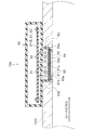
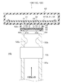
図8に示すように、配管125bの下流端と水素センサ10Bとは、事前試験等によって求められた所定間隔をあけて配置され、大気に開放された第1希釈部D2(希釈空間)を構成している。つまり、第1希釈部D2は、クリーニング弁125と水素センサ10B(10C、10D)との間に配置されている。そして、第1希釈部D2は、配管125bからの水素を自己拡散させ、水素を大気(希釈用ガス)で希釈する機能を有している。
As shown in FIG. 8, the downstream end of the
クリーニング弁125は、クリーニング弁124と同様に、ソレノイドによって駆動する常閉型の電磁弁(弁装置)であって、例えばソレノイドによって駆動するゲート弁によって構成され、ECU150から開弁指令が入力されている間、所定の開状態(開度)を維持するようになっている。
そして、ECU150が、クリーニング弁125の開弁時間/閉弁時間を例えばPWM制御することによって、クリーニング弁125を通って、第1希釈部D2に向かう水素(高濃度の水素)の流量が容易に制御され、その結果、水素センサ10B(10C、10D)の検知素子21に向かう水素濃度が制御されるようになっている。
The cleaning
Then, the
この場合において、大気圧(大気圧)が低くなると、第1希釈部D2において水素が大気(希釈用ガス)によって希釈され難くなるので、大気圧を検出する大気圧センサを備える構成とし、燃料電池車200が高地を走行することによって、大気圧が低くなるにつれて、クリーニング弁125の開弁時間を短くなるように補正する構成としてもよい。
In this case, when the atmospheric pressure (atmospheric pressure) becomes low, hydrogen becomes difficult to be diluted by the atmosphere (dilution gas) in the first dilution section D2. Therefore, the fuel cell is configured to include an atmospheric pressure sensor that detects the atmospheric pressure. A configuration may be adopted in which the opening time of the
すなわち、本実施形態において、水素タンク121は、燃料電池スタック110に水素(燃料ガス)を供給するだけでなく、水素センサ10A〜10Dにクリーング用の水素も供給可能であるので、燃料電池車200単体でもクリーニングを実行可能となっている。
That is, in the present embodiment, the
<IG>
IG141は、燃料電池車200(燃料電池システム100、水素検出システム1)の起動スイッチであり、運転席周りに配置されている。そして、IG141は、そのON信号/OFF信号をECU150に出力するようになっている。
<IG>
The
<ECU>
ECU150は、燃料電池車200(燃料電池システム100、水素検出システム1)を電子制御する制御装置であり、CPU、ROM、RAM、各種インタフェイス、電子回路などを含んで構成されており、その内部に記憶されたプログラムに従って、各種機能を発揮し、各種機器を制御するようになっている。ECU150の具体的な動作は後で説明する。
<ECU>
The
≪燃料電池車の動作≫
次に、燃料電池車200の動作を説明する。
≪Operation of fuel cell vehicle≫
Next, the operation of the
<起動モード>
まず、図9を参照して、燃料電池車200の起動時(始動時)における起動モードでの動作を説明する。
なお、IG141がONされると、そのON信号を検知したECU150は、図9の処理をスタートさせる。また、ここでは、水素センサ10Aに関係する動作を説明し、水素センサ10B〜10Dについての動作は同様であるので省略する。
<Startup mode>
First, with reference to FIG. 9, the operation in the startup mode when the
When
さらに、ECU150は、以下説明する水素センサ10Aに関係する処理に並行して、燃料電池スタック110を発電させるための処理も実行する。
すなわち、ECU150は、配管121aに設けられた遮断弁(図示しない)を開き、アノード流路111に水素を供給しつつ、パージ弁123を間欠的に開き、アノード流路111における水素濃度を上昇させる。これに並行して、ECU150は、コンプレッサ131を作動させ、カソード流路112に空気(酸素)を供給する。そうすると、燃料電池スタック110のOCV(Open Circuit Voltage、開回路電圧)が上昇し、燃料電池スタック110は発電可能な状態に近づく。
Further, the
That is, the
そして、OCVが発電開始可能と判断される所定OCV以上になった場合、ECU150は、燃料電池スタック110の出力端子に接続された発電制御器(図示しない)を制御し、燃料電池スタック110から電流を取り出し、燃料電池スタック110の発電を開始させ、発電電力を外部負荷(走行用のモータ等)に供給する。この場合において、コンプレッサ131の回転速度、燃料電池スタック110の発電電力は、発電要求量(アクセル開度等)が大きくなるにつれて、大きくなる関係となる。
When the OCV becomes equal to or higher than a predetermined OCV at which it is determined that power generation can be started, the
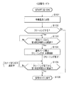
以下、水素センサ10Aに関係する処理を説明する。
ステップS101において、ECU150は、水素センサ10Aの検知素子21及び補償素子22を待機温度に加熱する。
待機温度は、本実施形態では、水素センサ10Aのクリーニング時(感度回復処理の実行時)、脱離温度以上の最適脱離温度範囲の温度から、クリーニング時の水素の燃焼熱による温度上昇分を差し引いた温度に設定される(図6、図7参照)。
Hereinafter, processing related to the
In step S101, the
In this embodiment, the standby temperature is the temperature rise due to the combustion heat of hydrogen during cleaning from the temperature in the optimum desorption temperature range equal to or higher than the desorption temperature when the
クリーニング時の水素の燃焼熱による温度上昇分は、例えば、事前試験等によって求められた所定温度上昇分とできる。
その他に、クリーニング時の水素の燃焼熱による温度上昇分は、クリーニング時に第1希釈部D1から検知素子21(水素センサ10A)に向かう水素濃度に基づいて算出することもできる。すなわち、第1希釈部D1による希釈後の水素濃度に対応して待機温度を設定し、この待機温度となるように検知素子21に通電し加熱する構成とすることもできる。この場合において、クリーニング時に第1希釈部D1から検知素子21に向かう水素濃度は、クリーニング弁124の開弁時間と、カソードオフガスの流量とに基づいて算出される。
The temperature increase due to the combustion heat of hydrogen at the time of cleaning can be, for example, a predetermined temperature increase obtained by a preliminary test or the like.
In addition, the temperature rise due to the combustion heat of hydrogen during cleaning can also be calculated based on the hydrogen concentration from the first dilution part D1 toward the sensing element 21 (
具体的には、ECU150は、前記待機温度に対応した待機温度加熱指令を、制御回路51(図5参照)を介して電圧発生回路52に出力する。そして、電圧発生回路52は、外部電源70からの電力を、待機温度加熱指令(待機温度)に対応した待機電圧に変換したうえで、ブリッジ回路Bに供給する。そうすると、検知素子21及び補償素子22は、通電により昇温し、待機温度に加熱される。
Specifically,
ステップS102において、ECU150は、検知素子21(水素センサ10A)をクリーニングする必要があるか否か(感度回復要求があるか否か)を判定する。
具体的には、現在、検知素子21に付着するシリコン化合物の付着量が、感度を回復させるためクリーニングするべきと判断される所定付着量以上である場合、クリーニングする必要があると判定される。
In step S102, the
Specifically, when the adhesion amount of the silicon compound adhering to the
ここで、検知素子21に付着するシリコン化合物の付着量は、水素センサ10Aの使用時間、燃料電池スタック110の発電時間(積算発電電力量)、燃料電池システム100(燃料電池車200)の作動時間(IG141のON時間)、等と比例関係であるから、(1)前回のクリーニングから現在までの水素センサ10Aの積算使用時間が所定積算使用時間以上である場合、(2)前回のクリーニングから現在までの燃料電池スタック110の積算発電時間(積算発電電力量)が、所定積算発電時間(所定積算発電電力量)以上である場合、(3)前回のクリーニングから現在までの燃料電池システム100(燃料電池車200)の作動時間が所定作動時間以上である場合、クリーニングする必要があると判定される。
Here, the adhesion amount of the silicon compound adhering to the
ここで、本願発明者等は、水素センサ10Aが所定水素濃度範囲の雰囲気で使用された場合、シリコン付着量が増加する傾向がある、という知見を得ている。つまり、シリコン化合物の付着しやすい水素濃度範囲が存在する、という知見を得ている。そこで、このような知見に基づいて、水素センサ10Aの検出する水素濃度が前記所定水素濃度範囲である時間を考慮して、今回の使用時間等を補正してもよい。
Here, the inventors of the present application have found that when the
クリーニングする必要があると判定した場合(S102・Yes)、ECU150の処理はステップS103に進む。一方、クリーニングする必要がないと判定した場合(S102・No)、ECU150の処理はステップS106に進む。
If it is determined that cleaning is necessary (S102, Yes), the process of the
ステップS103において、ECU150は、前回パージ(パージ弁123の閉弁)から第3所定時間Δt3経過したか否か判定する。
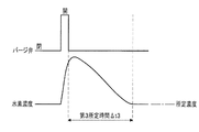
ここで、パージ弁123は、前記したように、ECU150によって所定開弁時間にて間欠的に開かれている。したがって、図12に示すように、パージ弁123の開弁に連動して、第1希釈部D1(図3参照)における水素濃度は上昇し、パージ弁123の閉弁後、配管132bを通流するカソードオフガス(希釈用ガス)で希釈され、徐々に低下する。そして、第3所定時間Δt3は、パージ弁123の閉弁から第1希釈部D1における水素濃度が所定濃度に低下する時間設定されている。所定濃度は、その後にクリーニング弁124を開弁し、配管132bに高濃度の水素を噴射しても、この高濃度の水素が第1希釈部D1で良好に希釈され、適切な水素濃度になり、その適切な水素濃度である水素の燃焼熱により、検知素子21が最適脱離温度範囲となるように設定される。
In step S103, the
Here, as described above, the
よって、パージ弁123の開弁時間が可変する構成の場合、パージ弁123の開弁時間が長くなるにつれて、第3所定時間Δt3が長くなるように補正してもよい。また、カソードオフガスの流量が多くなると、水素が希釈され易くなり、水素濃度が速やかに低下するので、流量センサ134の検出する空気の流量から推定されるカソードオフガスの流量が多くなるにつれて、第3所定時間Δt3が短くなるように補正してもよい。
Therefore, when the valve opening time of the
第3所定時間Δt3経過したと判定した場合(S103・Yes)、ECU150の処理はステップS104に進む。一方、第3所定時間Δt3経過していないと判定した場合(S103・No)、ECU150はステップS103の判定を繰り返す。
When it is determined that the third predetermined time Δt3 has elapsed (S103: Yes), the processing of the
ステップS104において、ECU150は、通常パージを禁止、つまり、パージ弁123の開弁を禁止し、閉じたまま維持する。
In step S104, the
これに並行して、ステップS104において、ECU150は、クリーニング弁124を開弁時間にて開弁する。そうすると、水素タンク121の高濃度の水素が、配管121a、配管124a、配管124bを通って、配管132bに噴射される。そうすると、噴射された水素は、第1希釈部D1において、カソードオフガス(希釈用ガス)によって良好に希釈され、適切な水素濃度になる。そして、この適切な水素濃度の水素が、水素センサ10Aの検知素子21に吹き付けられ、水素の燃焼熱により、検知素子21の温度が最適脱離温度範囲となる(図7参照)。これにより、検知素子21に付着していたシリコン化合物が、検知素子21から脱離し(図6参照)、検知素子21(水素センサ10A)の感度が回復する。そして、ECU150が、クリーニング弁124を閉弁することにより、クリーニング完了となる。
In parallel with this, in step S104, the
ここで、クリーニング弁124を開弁する開弁時間は、事前試験等によって予め設定された固定時間でもよいが、流量センサ134の検出する空気の流量から推定されるカソードオフガスの流量が多くなるにつれて、配管132bに噴射される水素が増加するように、開弁時間が長くなるように補正してもよい。
Here, the opening time for opening the
ステップS105において、ECU150は、ステップS104のクリーニング完了(感度回復処理の完了後)から第1所定時間Δt1経過したか否か判定する。
In step S105, the
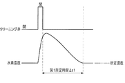
ここで、クリーニング弁124が、ステップS104で開弁されると、図13に示すように、第1希釈部D1(図3参照)における水素は上昇し、クリーニング弁124の閉弁後、配管132bを通流するカソードオフガス(希釈用ガス)で希釈され、徐々に低下する。そして、第1所定時間Δt1は、クリーニング弁124の閉弁から第1希釈部D1における水素濃度が所定濃度に低下する時間設定されている。所定濃度は、その後にクリーニング弁124を開弁し、配管132bに高濃度の水素を噴射しても、この高濃度の水素が第1希釈部D1で良好に希釈され、適切な水素濃度になり、その適切な水素濃度である水素の燃焼熱により、検知素子21が最適脱離温度範囲となるように設定される。
Here, when the cleaning
第1所定時間Δt1経過したと判定した場合(S105・Yes)、ECU150の処理はステップS106に進む。
When it is determined that the first predetermined time Δt1 has elapsed (S105, Yes), the processing of the
一方、第1所定時間Δt1経過していないと判定した場合(S105・No)、ECU150はステップS105の判定を繰り返す。このようにステップS105の判定を繰り返す場合、つまり、クリーニング弁124の閉弁から第1所定時間Δt1経過していない場合、ECU150は、コンプレッサ131(希釈用ガス通流手段)を作動しているので、第1希釈部D1をカソードオフガス(希釈用ガス)が通流し、第1希釈部D1における水素濃度が速やかに低下し、次回のクリーニングを迅速に実行可能となる。
On the other hand, when it is determined that the first predetermined time Δt1 has not elapsed (S105 · No), the
ステップS106において、ECU150は、起動モードによる動作を終了し、図10の定常モードによる動作に移行させる。
In step S106, the
<定常モード>
次に、図10を参照して、燃料電池車200の定常時における定常モードでの動作を説明する。
なお、燃料電池スタック110には水素及び空気が供給され、燃料電池スタック110は発電要求量に対応して発電している。また、パージ弁123は、ECU150によって間欠的に開かれている。
<Stationary mode>
Next, the operation in the steady mode when the
Note that hydrogen and air are supplied to the
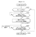
ステップS201において、ECU150は、前回クリーニング(S204)から第2所定時間Δt2経過したか否か判定する。
なお、前回、第2所定時間Δt2経過した場合(S201・Yes)において、クリーニングしないと判定しているとき(S202・No)、クリーニングしないと判定した時を起算点とする。また、第2所定時間Δt2は、第1所定時間Δt1以上に設定される。
In step S201, the
When the second predetermined time Δt2 has passed (S201 / Yes), it is determined that the cleaning is not performed (S202 / No), and the time when it is determined that the cleaning is not performed is set as the starting point. The second predetermined time Δt2 is set to be equal to or longer than the first predetermined time Δt1.
第2所定時間Δt2経過したと判定した場合(S201・Yes)、ECU150の処理はステップS202に進む。一方、第2所定時間Δt2経過していないと判定した場合(S201・No)、ECU150はステップS201の判定を繰り返す。
When it is determined that the second predetermined time Δt2 has elapsed (S201 / Yes), the processing of the
ステップS202において、ECU150は、ステップS102と同様に、検知素子21(水素センサ10A)をクリーニングする必要があるか否か(感度回復要求があるか否か)を判定する。
クリーニングすると必要がある判定した場合(S202・Yes)、ECU150の処理はステップS203に進む。一方、クリーニングする必要がないと判定した場合(S202・No)、ECU150の処理はステップS201に進む。
In step S202, the
When it is determined that it is necessary to perform cleaning (S202 / Yes), the process of the
ステップS203において、ECU150は、ステップS103と同様に、前回パージから第3所定時間Δt3経過したか否か判定する。
第3所定時間Δt3経過したと判定した場合(S203・Yes)、ECU150の処理はステップS204に進む。一方、第3所定時間Δt3経過していないと判定した場合(S203・No)、ECU150はステップS203の判定を繰り返す。
In step S203, the
When it is determined that the third predetermined time Δt3 has elapsed (S203: Yes), the processing of the
ステップS204において、ECU150は、ステップS104と同様に、通常パージを禁止、つまり、パージ弁123の開弁を禁止し、閉じたまま維持した状態で、クリーニング弁124を開弁時間にて開弁し、水素センサ10Aのクリーニングを実行する。
In step S204, as in step S104, the
ステップS205において、ECU150は、ステップS105と同様に、ステップS204のクリーニング完了から第1所定時間Δt1経過したか否か判定する。
第1所定時間Δt1経過したと判定した場合(S205・Yes)、ECU150の処理はステップS201に進む。
In step S205, the
When it is determined that the first predetermined time Δt1 has elapsed (S205: Yes), the processing of the
一方、第1所定時間Δt1経過していないと判定した場合(S205・No)、ECU150はステップS205の判定を繰り返す。このようにステップS205の判定を繰り返す場合、ECU150は、コンプレッサ131(希釈用ガス通流手段)を作動しているので、第1希釈部D1をカソードオフガス(希釈用ガス)が通流し、第1希釈部D1における水素濃度が速やかに低下し、次回のクリーニングを迅速に実行可能となる。
On the other hand, when it is determined that the first predetermined time Δt1 has not elapsed (S205 · No), the
<停止モード>
次に、図11を参照して、燃料電池車200の停止時における停止モードでの動作を説明する。
なお、IG141がOFFされると、そのOFF信号を検知したECU150は、図11の処理をスタートさせる。また、ECU150は、燃料電池スタック110の出力端子に接続された発電制御装置(図示しない)を制御し、燃料電池スタック110の発電を停止させる。
<Stop mode>
Next, the operation in the stop mode when the
When
ステップS301において、ECU150は、ステップS102、S202と同様に、検知素子21(水素センサ10A)をクリーニングする必要があるか否か(感度回復要求があるか否か)を判定する。
In step S301, the
クリーニングすると必要がある判定した場合(S301・Yes)、ECU150の処理はステップS302に進む。一方、クリーニングする必要がないと判定した場合(S301・No)、ECU150の処理はステップS305に進む。
If it is determined that cleaning is necessary (S301: Yes), the process of the
ステップS302において、ECU150は、ステップS103、S203と同様に、前回パージから第3所定時間Δt3経過したか否か判定する。
第3所定時間Δt3経過したと判定した場合(S302・Yes)、ECU150の処理はステップS303に進む。一方、第3所定時間Δt3経過していないと判定した場合(S302・No)、ECU150はステップS302の判定を繰り返す。
In step S302, the
If it is determined that the third predetermined time Δt3 has elapsed (S302: Yes), the processing of the
ステップS303において、ECU150は、ステップS104、S204と同様に、通常パージを禁止、つまり、パージ弁123の開弁を禁止し、閉じたまま維持した状態で、クリーニング弁124を開弁時間にて開弁し、水素センサ10Aのクリーニングを実行する。
In step S303, as in steps S104 and S204, the
ステップS304において、ECU150は、ステップS105、S205と同様に、ステップS303のクリーニング完了から第1所定時間Δt1経過したか否か判定する。
第1所定時間Δt1経過したと判定した場合(S304・Yes)、ECU150の処理はステップS205に進む。
In step S304, the
When it is determined that the first predetermined time Δt1 has elapsed (S304, Yes), the processing of the
一方、第1所定時間Δt1経過していないと判定した場合(S304・No)、ECU150はステップS304の判定を繰り返す。このようにステップS304の判定を繰り返す場合、ECU150は、コンプレッサ131(希釈用ガス通流手段)を作動しているので、第1希釈部D1をカソードオフガス(希釈用ガス)が通流し、第1希釈部D1における水素濃度が速やかに低下する。
On the other hand, when it is determined that the first predetermined time Δt1 has not elapsed (S304, No), the
ステップS305において、ECU150は、配管121aの遮断弁(図示しない)を閉じ、水素の供給を停止する。また、ECU150は、コンプレッサ131を停止させる。これにより、燃料電池車200(燃料電池システム100)は停止状態となる。
In step S305, the
≪燃料電池車の効果≫
このような燃料電池車200によれば、次の効果を得る。
水素センサ10Aをクリーニングする必要があると判定される場合(感度回復要求時)、クリーニング弁124を開弁して水素を噴射し、水素の燃焼熱と、通電による発熱とによって、検知素子21を脱離温度以上に上昇させ、これに付着したシリコン化合物を意図的に脱離し、水素の検出感度を回復できる。したがって、水素センサ10Aによって長時間に亘って水素濃度を検出できる。
≪Effect of fuel cell car≫
According to such a
When it is determined that the
検知素子21への通電によって、検知素子21を待機温度に加熱し、この待機温度は、脱離温度から、クリーニング時における水素の燃焼による温度上昇分を差し引いた温度に設定するので、クリーニング時において、検知素子21の温度が上昇し過ぎることなく、また、通電に要する電力を適切とできる。
By energizing the
前回のクリーニングの完了から、第1希釈部D1における水素濃度が所定濃度に低下する第1所定時間Δt1の経過以後(S105・Yes、S205・Yes、S304・Yes)、今回のクリーニングを開始するので、検知素子21に向かう水素濃度が高すぎることはなく、水素の燃焼熱によって検知素子21が予想以上に昇温することはない。
また、第1所定時間Δt1以上の第2所定時間Δt2経過毎に(S201・Yes)、クリーニングを繰り返すので、水素センサ10Aの感度を第2所定時間Δt2経過毎に回復できる。
Since this cleaning is started after the elapse of the first predetermined time Δt1 during which the hydrogen concentration in the first dilution section D1 decreases to a predetermined concentration after the completion of the previous cleaning (S105 Yes, S205 Yes, S304 Yes) The hydrogen concentration toward the
Since cleaning is repeated every time the second predetermined time Δt2 that is equal to or greater than the first predetermined time Δt1 (Yes in S201), the sensitivity of the
クリーニングの完了から第1所定時間Δt1経過するまで(S105・No、S205・No、S304・No)、第1希釈部D1をカソードオフガス(希釈用ガス)が通流するので、第1希釈部D1における水素濃度を速やかに低下させ、次回のクリーニングを実行できる。 Since the cathode off-gas (dilution gas) flows through the first dilution part D1 until the first predetermined time Δt1 has elapsed from the completion of cleaning (S105 · No, S205 · No, S304 · No), the first dilution part D1 The hydrogen concentration in can be quickly reduced and the next cleaning can be executed.
パージ弁123の閉弁から、第1希釈部D1における水素濃度が所定濃度に低下する第3所定時間Δt3の経過以後(S103・Yes、S201・Yes、S302・Yes)、クリーニングを開始するので、検知素子21に向かう水素濃度が予想以上にならず、水素の燃焼熱によって検知素子21が予想以上に昇温することはない。
After the
≪変形例≫
以上、本発明の一実施形態について説明したが、本発明はこれに限定されず、例えば、次のように変更できる。
≪Modification≫
As mentioned above, although one Embodiment of this invention was described, this invention is not limited to this, For example, it can change as follows.
前記した実施形態では、白金等の触媒金属からなる検知素子21がコイル状である構成を例示したが(図4参照)、検知素子21の形状はこれに限定されず、その他に例えば、図14に示すように、薄膜状の検知素子21Aとしてもよい。このようにすれば、ハウジング63の高さ方向を短かくし、水素センサ10Aを小型化できる。また、薄膜状とすれば、検知素子21Aの単位体積当たりの表面積が大きくなるので、水素の接触可能面積が大きくなり、検知素子21Aが速やかに昇温可能となる。なお、この場合、補償素子22Aも薄膜状とする。
In the above-described embodiment, the
前記した実施形態では、電圧発生回路52に対して、検知素子21と補償素子22とが直列に接続された構成を例示したが、図15に示すように、並列に接続された構成でもよい。すなわち、図15のブリッジ回路Bでは、検知素子21と第1抵抗素子31とが直列に接続されることで第1辺20が構成され、補償素子22と第2抵抗素子32とが直列に接続されることで第2辺30が構成されている。
In the above-described embodiment, the configuration in which the
前記した実施形態では、クリーニング弁124(弁装置)が、所定の開状態を維持可能であるゲート弁等から構成され、その開弁時間/閉弁時間を制御することによって、検知素子21に向かう水素濃度を制御する構成を例示したが、その他に例えば、クリーニング弁124(弁装置)が、所望の開度に調整可能であるバタフライ弁等から構成され、その開度の制御することによって、検知素子21に向かう水素濃度を制御する構成としてもよい。
In the above-described embodiment, the cleaning valve 124 (valve device) is configured by a gate valve or the like that can maintain a predetermined open state, and is directed to the
1 水素検出システム
10A、10B、10C、10D 水素センサ
21 検知素子
51 制御回路(加熱手段、通電手段)
52 電圧発生回路(加熱手段、通電手段)
70 外部電源(加熱手段、通電手段)
110 燃料電池スタック
121 水素タンク(水素貯蔵手段)
123 パージ弁
124、125 クリーニング弁(通流調整手段)
124a、124b、125a、125b 配管(水素案内配管)
131 コンプレッサ(希釈用ガス通流手段)
133 サイレンサ(第2希釈部)
150 ECU(制御手段)
D1、D2 第1希釈部
Δt1 第1所定時間
Δt2 第2所定時間
Δt3 第3所定時間
DESCRIPTION OF
52 Voltage generation circuit (heating means, energization means)
70 External power supply (heating means, energization means)
110
123
124a, 124b, 125a, 125b Piping (hydrogen guide piping)
131 Compressor (Dilution gas flow means)
133 Silencer (2nd dilution part)
150 ECU (control means)
D1, D2 First dilution unit Δt1 first predetermined time Δt2 second predetermined time Δt3 third predetermined time
Claims (13)
前記検知素子を加熱する加熱手段と、
高濃度の水素を貯蔵する水素貯蔵手段と、
前記水素貯蔵手段の水素を前記検知素子に案内する水素案内配管と、
前記水素案内配管に設けられ、水素の通流を調整する通流調整手段と、
前記通流調整手段と前記検知素子との間で、前記水素貯蔵手段からの水素を希釈用ガスで希釈する第1希釈部と、
前記加熱手段及び前記通流調整手段を制御する制御手段と、
を備え、
前記制御手段は、
前記水素センサの感度回復要求のある感度回復要求時、
前記加熱手段で加熱されている前記検知素子の温度が水素の燃焼熱によって当該検知素子に付着したシリコンの脱離する脱離温度以上になるように、前記通流調整手段によって前記第1希釈部から前記検知素子に向かう水素濃度を制御する感度回復処理を実行する
ことを特徴とする水素検出システム。 A hydrogen sensor having a sensing element formed and exposed from a catalytic metal that combusts hydrogen to generate combustion heat, and detects a hydrogen concentration based on a change value of the sensing element that changes in response to combustion heat;
Heating means for heating the sensing element;
Hydrogen storage means for storing high concentration of hydrogen;
A hydrogen guide pipe for guiding the hydrogen of the hydrogen storage means to the detection element;
A flow adjusting means for adjusting the flow of hydrogen provided in the hydrogen guide pipe;
A first dilution section for diluting hydrogen from the hydrogen storage means with a diluting gas between the flow adjusting means and the sensing element;
Control means for controlling the heating means and the flow adjustment means;
With
The control means includes
At the time of sensitivity recovery request with the sensitivity recovery request of the hydrogen sensor,
The first diluting section is adjusted by the flow adjusting means so that the temperature of the detection element heated by the heating means is equal to or higher than the desorption temperature at which silicon adhering to the detection element is desorbed by the combustion heat of hydrogen. A hydrogen recovery system is characterized in that a sensitivity recovery process is performed to control the hydrogen concentration toward the sensing element.
前記待機温度は、前記脱離温度から、感度回復要求時における水素の燃焼による温度上昇分を差し引いた温度である
ことを特徴とする請求項1に記載の水素検出システム。 The control means heats the sensing element to a standby temperature by the heating means,
2. The hydrogen detection system according to claim 1, wherein the standby temperature is a temperature obtained by subtracting a temperature increase due to hydrogen combustion at the time of sensitivity recovery request from the desorption temperature.
前記加熱手段は、前記通電手段を含み、前記検知素子に通電することで、前記検知素子の温度を上昇させる
ことを特徴とする請求項1又は請求項2に記載の水素検出システム。 The hydrogen sensor includes an energization means for energizing the sensing element, and detects a hydrogen concentration based on an increase in resistance value of the sensing element due to hydrogen combustion,
The hydrogen detection system according to claim 1, wherein the heating unit includes the energization unit, and energizes the detection element to increase the temperature of the detection element.
前記制御手段は、前記弁装置の開弁時間/閉弁時間を制御することによって、前記検知素子に向かう水素濃度を制御する
ことを特徴とする請求項1から請求項3のいずれか1項に記載の水素検出システム。 The flow adjustment means includes a valve device capable of maintaining a predetermined open state,
The said control means controls the hydrogen concentration which goes to the said detection element by controlling the valve opening time / valve closing time of the said valve apparatus. Any one of Claims 1-3 characterized by the above-mentioned. The described hydrogen detection system.
前記制御手段は、前記弁装置の開度の制御することによって、前記検知素子に向かう水素濃度を制御する
ことを特徴とする請求項1から請求項3のいずれか1項に記載の水素検出システム。 The flow adjustment means includes a valve device that can be adjusted to a desired opening degree,
The hydrogen detection system according to any one of claims 1 to 3, wherein the control means controls a hydrogen concentration toward the sensing element by controlling an opening degree of the valve device. .
ことを特徴とする請求項1から請求項5のいずれか1項に記載の水素検出システム。 The control means starts the current sensitivity recovery process after the elapse of a first predetermined time when the hydrogen concentration in the first dilution section decreases to a predetermined concentration from the completion of the previous sensitivity recovery process. The hydrogen detection system according to any one of claims 1 to 5.
ことを特徴とする請求項6に記載の水素検出システム。 The hydrogen detection system according to claim 6, wherein the control unit repeats sensitivity recovery processing every second predetermined time that is equal to or longer than the first predetermined time.
前記制御手段は、感度回復処理の完了後、前記希釈用ガス通流手段によって希釈用ガスを通流させる
ことを特徴とする請求項1から請求項7のいずれか1項に記載の水素検出システム。 A dilution gas flow means for flowing a dilution gas through the first dilution section;
8. The hydrogen detection system according to claim 1, wherein after the sensitivity recovery process is completed, the control unit causes the dilution gas flow unit to pass dilution gas. 9. .
前記水素案内配管は、前記水素センサよりも上流の前記カソードオフガス流路に合流しており、
前記第1希釈部は、前記水素案内配管と前記水素センサとの間の前記カソードオフガス流路であり、
希釈用ガスはカソードオフガスである
ことを特徴とする請求項1から請求項8のいずれか1項に記載の水素検出システム。 The hydrogen sensor is attached to a cathode offgas passage through which a cathode offgas from the cathode of the fuel cell flows,
The hydrogen guide pipe is joined to the cathode offgas flow channel upstream of the hydrogen sensor,
The first dilution part is the cathode offgas flow path between the hydrogen guide pipe and the hydrogen sensor,
The hydrogen detection system according to any one of claims 1 to 8, wherein the dilution gas is a cathode off gas.
前記アノードオフガス流路にはアノードオフガスを排出する場合に開くパージ弁が設けられており、
前記制御手段は、前記パージ弁の閉弁から、前記第1希釈部における水素濃度が所定濃度に低下する第3所定時間の経過以後、感度回復処理を開始する
ことを特徴とする請求項9に記載の水素検出システム。 An anode offgas passage for discharging anode offgas from the anode of the fuel cell joins the cathode offgas passage upstream of the hydrogen guide pipe,
The anode off gas flow path is provided with a purge valve that opens when the anode off gas is discharged,
The control means starts the sensitivity recovery process after a lapse of a third predetermined time from when the purge valve is closed until the hydrogen concentration in the first dilution section decreases to a predetermined concentration. The described hydrogen detection system.
ことを特徴とする請求項9又は請求項10に記載の水素検出システム。 11. The hydrogen detection system according to claim 9, wherein the cathode off-gas flow channel downstream of the hydrogen sensor includes a second dilution unit.
前記第1希釈部は、前記水素案内配管の下流端と前記水素センサとの間において、大気に開放された希釈空間であり、
前記希釈用ガスは、大気である
ことを特徴とする請求項1から請求項8のいずれか1項に記載の水素検出システム。 The hydrogen sensor is disposed in an open air space that is open to the atmosphere,
The first dilution part is a dilution space opened to the atmosphere between the downstream end of the hydrogen guide pipe and the hydrogen sensor,
The hydrogen detection system according to any one of claims 1 to 8, wherein the dilution gas is the atmosphere.
前記水素貯蔵装置は、前記燃料電池に燃料ガスとして水素を供給する
ことを特徴とする請求項1から請求項12のいずれか1項に記載の水素検出システム。 It has a fuel cell and is mounted on a fuel cell vehicle that runs on the power of the fuel cell,
The hydrogen detection system according to any one of claims 1 to 12, wherein the hydrogen storage device supplies hydrogen as a fuel gas to the fuel cell.
Priority Applications (4)
| Application Number | Priority Date | Filing Date | Title |
|---|---|---|---|
| JP2011021573A JP2012163341A (en) | 2011-02-03 | 2011-02-03 | Hydrogen detection system |
| CN2012100202502A CN102628825A (en) | 2011-02-03 | 2012-01-29 | Hydrogen detection system |
| US13/364,757 US8821797B2 (en) | 2011-02-03 | 2012-02-02 | Hydrogen detection system |
| DE102012201647A DE102012201647A1 (en) | 2011-02-03 | 2012-02-03 | Hydrogen detection system |
Applications Claiming Priority (1)
| Application Number | Priority Date | Filing Date | Title |
|---|---|---|---|
| JP2011021573A JP2012163341A (en) | 2011-02-03 | 2011-02-03 | Hydrogen detection system |
Publications (1)
| Publication Number | Publication Date |
|---|---|
| JP2012163341A true JP2012163341A (en) | 2012-08-30 |
Family
ID=46587124
Family Applications (1)
| Application Number | Title | Priority Date | Filing Date |
|---|---|---|---|
| JP2011021573A Pending JP2012163341A (en) | 2011-02-03 | 2011-02-03 | Hydrogen detection system |
Country Status (4)
| Country | Link |
|---|---|
| US (1) | US8821797B2 (en) |
| JP (1) | JP2012163341A (en) |
| CN (1) | CN102628825A (en) |
| DE (1) | DE102012201647A1 (en) |
Cited By (1)
| Publication number | Priority date | Publication date | Assignee | Title |
|---|---|---|---|---|
| JP2016118438A (en) * | 2014-12-19 | 2016-06-30 | 日産自動車株式会社 | Gas detector for electrochemical device evaluation apparatus and method for restoring gas sensor sensitivity of gas detector |
Families Citing this family (12)
| Publication number | Priority date | Publication date | Assignee | Title |
|---|---|---|---|---|
| JP2012163341A (en) * | 2011-02-03 | 2012-08-30 | Honda Motor Co Ltd | Hydrogen detection system |
| CN103474685A (en) * | 2013-09-05 | 2013-12-25 | 上海新源动力有限公司 | Safe hydrogen emission method for fuel cell |
| DE102013224246A1 (en) * | 2013-11-27 | 2015-05-28 | Robert Bosch Gmbh | Apparatus and method for determining the H2 content of H2 / natural gas mixtures |
| DE102014207450A1 (en) * | 2014-04-17 | 2015-10-22 | Bayerische Motoren Werke Aktiengesellschaft | A method for purging a fuel cell and apparatus for carrying out the method |
| US11541737B2 (en) * | 2016-12-28 | 2023-01-03 | Nuvoton Technology Corporation Japan | Gas detection device, gas detection system, fuel cell vehicle, and gas detection method |
| CN106990137A (en) * | 2017-03-13 | 2017-07-28 | 英吉森安全消防系统(上海)有限公司 | A kind of novel pyrolytic particle sensor |
| CN111024752B (en) * | 2019-12-24 | 2022-05-17 | 沃尔特电子(苏州)有限公司 | Hydrogen fuel cell automobile exhaust check out test set |
| CN112903599A (en) * | 2021-01-13 | 2021-06-04 | 中国科学院上海应用物理研究所 | High-precision trace water oxygen measurement system |
| JP2022147043A (en) * | 2021-03-23 | 2022-10-06 | 本田技研工業株式会社 | fuel cell vehicle |
| CN113270619A (en) * | 2021-04-15 | 2021-08-17 | 黄冈格罗夫氢能汽车有限公司 | System for reducing concentration of tail-exhausted hydrogen of fuel cell system |
| FR3140867A1 (en) * | 2022-10-18 | 2024-04-19 | Airbus | INSTALLATION INCLUDING A DEVICE FOR REGULATING A DIHYDROGEN CONCENTRATION |
| FR3140911A1 (en) * | 2022-10-18 | 2024-04-19 | Airbus | INSTALLATION INCLUDING A DEVICE FOR REGULATING A DIHYDROGEN CONCENTRATION |
Citations (5)
| Publication number | Priority date | Publication date | Assignee | Title |
|---|---|---|---|---|
| JP2000146882A (en) * | 1998-11-13 | 2000-05-26 | Shimadzu Corp | Gas measuring device |
| JP2003302362A (en) * | 2002-04-05 | 2003-10-24 | Honda Motor Co Ltd | Fault-judging apparatus for gas detection means and fault-judging apparatus for hydrogen detection means |
| JP2007024627A (en) * | 2005-07-14 | 2007-02-01 | Nissan Motor Co Ltd | Hydrogen detection device and fuel cell system |
| JP2007048578A (en) * | 2005-08-09 | 2007-02-22 | Toyota Motor Corp | Fuel cell system |
| WO2011145492A1 (en) * | 2010-05-17 | 2011-11-24 | 本田技研工業株式会社 | Catalytic combustion type gas sensor |
Family Cites Families (12)
| Publication number | Priority date | Publication date | Assignee | Title |
|---|---|---|---|---|
| US4854155A (en) * | 1988-10-19 | 1989-08-08 | Mine Safety Appliances Company | Combustible gas detector having catalytic sensor stabilizing network |
| US5985673A (en) * | 1994-12-22 | 1999-11-16 | Arizona Baord Of Regents | Method for regeneration of a sensor |
| US6060025A (en) * | 1997-09-23 | 2000-05-09 | Eic Laboratories, Incorporated | Systems and methods for catalyst reactivation |
| JP3650266B2 (en) * | 1998-05-18 | 2005-05-18 | 株式会社日立製作所 | Control device for oxygen sensor with heater |
| JP3836440B2 (en) | 2002-05-13 | 2006-10-25 | 本田技研工業株式会社 | Degradation diagnosis method for gas sensor |
| JP3830857B2 (en) | 2002-05-13 | 2006-10-11 | 本田技研工業株式会社 | Gas detection system |
| JP2006153598A (en) | 2004-11-26 | 2006-06-15 | Honda Motor Co Ltd | Gas detector and control method of gas detecting element |
| JP4598622B2 (en) * | 2005-08-01 | 2010-12-15 | 本田技研工業株式会社 | Gas sensor |
| JP4585402B2 (en) * | 2005-08-01 | 2010-11-24 | 本田技研工業株式会社 | Gas sensor |
| WO2007097025A1 (en) | 2006-02-27 | 2007-08-30 | Fis Inc. | Hydrogen gas sensor |
| JP2011021573A (en) | 2009-07-17 | 2011-02-03 | Toyota Motor Corp | Turbocharger |
| JP2012163341A (en) * | 2011-02-03 | 2012-08-30 | Honda Motor Co Ltd | Hydrogen detection system |
-
2011
- 2011-02-03 JP JP2011021573A patent/JP2012163341A/en active Pending
-
2012
- 2012-01-29 CN CN2012100202502A patent/CN102628825A/en active Pending
- 2012-02-02 US US13/364,757 patent/US8821797B2/en active Active
- 2012-02-03 DE DE102012201647A patent/DE102012201647A1/en not_active Withdrawn
Patent Citations (5)
| Publication number | Priority date | Publication date | Assignee | Title |
|---|---|---|---|---|
| JP2000146882A (en) * | 1998-11-13 | 2000-05-26 | Shimadzu Corp | Gas measuring device |
| JP2003302362A (en) * | 2002-04-05 | 2003-10-24 | Honda Motor Co Ltd | Fault-judging apparatus for gas detection means and fault-judging apparatus for hydrogen detection means |
| JP2007024627A (en) * | 2005-07-14 | 2007-02-01 | Nissan Motor Co Ltd | Hydrogen detection device and fuel cell system |
| JP2007048578A (en) * | 2005-08-09 | 2007-02-22 | Toyota Motor Corp | Fuel cell system |
| WO2011145492A1 (en) * | 2010-05-17 | 2011-11-24 | 本田技研工業株式会社 | Catalytic combustion type gas sensor |
Cited By (1)
| Publication number | Priority date | Publication date | Assignee | Title |
|---|---|---|---|---|
| JP2016118438A (en) * | 2014-12-19 | 2016-06-30 | 日産自動車株式会社 | Gas detector for electrochemical device evaluation apparatus and method for restoring gas sensor sensitivity of gas detector |
Also Published As
| Publication number | Publication date |
|---|---|
| DE102012201647A1 (en) | 2012-09-13 |
| CN102628825A (en) | 2012-08-08 |
| US20120201715A1 (en) | 2012-08-09 |
| US8821797B2 (en) | 2014-09-02 |
Similar Documents
| Publication | Publication Date | Title |
|---|---|---|
| JP2012163341A (en) | Hydrogen detection system | |
| CA2641188C (en) | Fuel cell system with regeneration of electrode activity during start or stop | |
| JP4598622B2 (en) | Gas sensor | |
| CN102449832B (en) | Fuel cell vehicle | |
| US10158132B2 (en) | Fuel cell system and method of controlling the fuel cell system | |
| WO2011145492A1 (en) | Catalytic combustion type gas sensor | |
| WO2008053727A1 (en) | Fuel cell system | |
| US8691460B2 (en) | Method of stopping operation of fuel cell system | |
| JP2008269841A (en) | Fuel cell system | |
| JP5009761B2 (en) | Fuel cell system and control method thereof | |
| JP5350601B2 (en) | Fuel cell system | |
| EP3021404B1 (en) | Fuel cell system and vehicle equipped with fuel cell | |
| JP2006153598A (en) | Gas detector and control method of gas detecting element | |
| JP2005251576A (en) | Fuel cell system and moving body mounting the same | |
| WO2016051951A1 (en) | Fuel cell system and control method therefor | |
| JPWO2014103101A1 (en) | Fuel cell system and method for recovering power generation performance of fuel cell in fuel cell system | |
| JP5239201B2 (en) | Fuel cell system and impurity discharge method in fuel cell system | |
| JP5186794B2 (en) | Fuel cell system and gas pressure adjustment method in fuel cell system | |
| JP5082311B2 (en) | Fuel cell system | |
| JP5199645B2 (en) | Fuel cell system | |
| US8241804B1 (en) | Method for controlling fuel cell system | |
| JP2013243007A (en) | Fuel cell system | |
| JP2012251951A (en) | Gas sensor | |
| JP5420855B2 (en) | Fuel cell system and control method thereof | |
| JP2013196905A (en) | Fuel cell system |
Legal Events
| Date | Code | Title | Description |
|---|---|---|---|
| A621 | Written request for application examination |
Free format text: JAPANESE INTERMEDIATE CODE: A621 Effective date: 20131128 |
|
| A977 | Report on retrieval |
Free format text: JAPANESE INTERMEDIATE CODE: A971007 Effective date: 20140625 |
|
| A131 | Notification of reasons for refusal |
Free format text: JAPANESE INTERMEDIATE CODE: A131 Effective date: 20140722 |
|
| A02 | Decision of refusal |
Free format text: JAPANESE INTERMEDIATE CODE: A02 Effective date: 20150127 |