JP2012163283A - Desiccant type ventilation fan - Google Patents
Desiccant type ventilation fan Download PDFInfo
- Publication number
- JP2012163283A JP2012163283A JP2011025118A JP2011025118A JP2012163283A JP 2012163283 A JP2012163283 A JP 2012163283A JP 2011025118 A JP2011025118 A JP 2011025118A JP 2011025118 A JP2011025118 A JP 2011025118A JP 2012163283 A JP2012163283 A JP 2012163283A
- Authority
- JP
- Japan
- Prior art keywords
- desiccant
- filter
- air
- insect
- air supply
- Prior art date
- Legal status (The legal status is an assumption and is not a legal conclusion. Google has not performed a legal analysis and makes no representation as to the accuracy of the status listed.)
- Pending
Links
Images


Abstract
Description
本発明は、外気と室内空気の入れ替えを行いながら室内の湿度調整をするデシカント式換気扇に関する。 The present invention relates to a desiccant type ventilation fan that adjusts indoor humidity while exchanging outside air and room air.
従来、室内の換気に加えて、シリカゲル等の吸湿材が付着されたデシカントロータにより湿度調整を行う場合があり、その具体例が特許文献1に記載されている。
特許文献1では、デシカントロータの端面に、室内に流入する外気の塵埃を捕捉する集塵フィルタが備えられ、浄化された空気を室内に送る設計がなされている。そして、集塵フィルタの塵埃が付着する面の裏側が風上となって、室内からの排気が行われるので、塵埃は集塵フィルタから脱離される仕組みになっている。
また、当然ながら集塵フィルタは塵埃だけでなく虫も捕捉するため、屋外から室内への虫の侵入も防ぐことが出来る。
Conventionally, in addition to indoor ventilation, humidity adjustment may be performed by a desiccant rotor to which a hygroscopic material such as silica gel is attached. A specific example is described in
In
Of course, the dust collecting filter captures not only dust but also insects, so that insects can be prevented from entering the room from the outside.
しかしながら、特許文献1では、集塵フィルタに付着した塵埃や虫は、室内からの排気によって全て取り除くことができないため定期的に集塵フィルタを取り替える必要があり、その取り替えの際に集塵フィルタに付着した虫が手に触れるおそれがあり、作業者に不快な思いを与えることになる。
本発明は、かかる事情に鑑みてなされるもので、作業者が虫に触れずにフィルタの取り替えが可能なデシカント式換気扇を提供することを目的とする。
However, in
The present invention has been made in view of such circumstances, and an object of the present invention is to provide a desiccant type ventilation fan in which an operator can replace a filter without touching insects.
前記目的に沿う本発明に係るデシカント式換気扇は、室内に外気を取り込む給気路と該室内の空気を排出する排気路がケーシング内に形成され、該給気路と該排気路の相対湿度が高い側から低い側に水分を移動させるデシカントロータを有するデシカント式換気扇において、前記給気路には、前記外気の流れに沿って前記デシカントロータの上流側に配置された集塵フィルタと、該集塵フィルタの更に上流側に配置され、開口部のある袋体を備える虫取りフィルタとが設けられ、該虫取りフィルタは該袋体の内側で虫を捕捉する。 In the desiccant-type exhaust fan according to the present invention that meets the above-mentioned object, an air supply path for taking outside air into the room and an exhaust path for discharging the indoor air are formed in the casing, and the relative humidity between the air supply path and the exhaust path is In a desiccant-type ventilation fan having a desiccant rotor that moves moisture from a high side to a low side, a dust collection filter disposed on the upstream side of the desiccant rotor along the flow of the outside air in the supply passage, and the collection filter There is provided an insect removing filter disposed on the further upstream side of the dust filter and provided with a bag body having an opening, and the insect catching filter catches insects inside the bag body.
本発明に係るデシカント式換気扇において、前記集塵フィルタ及び前記虫取りフィルタは、前記ケーシングの一側から取り外し可能であるのが好ましい。 In the desiccant-type ventilation fan according to the present invention, it is preferable that the dust collection filter and the insect filter are removable from one side of the casing.
本発明に係るデシカント式換気扇において、前記集塵フィルタ及び前記虫取りフィルタは、80〜180cmの高さ位置で前記ケーシング内に取り付けられるのが好ましい。 In the desiccant-type ventilation fan according to the present invention, it is preferable that the dust collection filter and the insect trapping filter are mounted in the casing at a height of 80 to 180 cm.
本発明に係るデシカント式換気扇において、前記虫取りフィルタは、前記袋体に連続して形成され前記開口部を囲む枠体を有し、該枠体には、該枠体を折り曲げて該開口部を閉じることが可能な折り目が設けられているのが好ましい。 In the desiccant-type ventilation fan according to the present invention, the insect trapping filter has a frame body that is formed continuously with the bag body and surrounds the opening, and the opening is obtained by folding the frame body to the frame body. It is preferable that a crease capable of closing is provided.
本発明に係るデシカント式換気扇は、給気路に、外気の流れに沿ってデシカントロータの上流側に配置された集塵フィルタと、集塵フィルタの更に上流側に配置され、開口部のある袋体を備える虫取りフィルタとが設けられているので、虫は、集塵フィルタに付着せず虫取りフィルタによって捕捉され、虫に触れることなく集塵フィルタの取り替えができる。また、虫取りフィルタは袋体の内側で虫を捕捉するので、虫取りフィルタの袋体の内側以外の部分、例えば外側を持つことにより、虫に触れることなく虫取りフィルタの取り替えが可能である。 The desiccant-type ventilation fan according to the present invention includes a dust collection filter disposed on the upstream side of the desiccant rotor along the flow of outside air in the air supply path, and a bag having an opening disposed further upstream of the dust collection filter. Since the insect removing filter provided with the body is provided, the insect does not adhere to the dust collecting filter and is captured by the insect removing filter, and the dust collecting filter can be replaced without touching the insect. Moreover, since the insect trapping filter captures insects inside the bag body, the insect trapping filter can be replaced without touching the insect by having a portion other than the inside of the insect trapping bag body, for example, the outside. .
本発明に係るデシカント式換気扇において、集塵フィルタ及び虫取りフィルタが、ケーシングの一側から取り外し可能である場合、集塵フィルタ及び虫取りフィルタの取り替えを効率的に行うことができる。 In the desiccant type exhaust fan according to the present invention, when the dust collection filter and the insect trapping filter are removable from one side of the casing, the dust collection filter and the insect trapping filter can be efficiently replaced.
本発明に係るデシカント式換気扇において、集塵フィルタ及び虫取りフィルタが、80〜180cmの高さ位置でケーシング内に取り付けられる場合、通常の身長の者が踏み台等を用いることなく手を伸ばして集塵フィルタ及び虫取りフィルタの取り替え作業を容易に行うことが可能である。 In the desiccant-type ventilation fan according to the present invention, when the dust collection filter and the insect trapping filter are mounted in the casing at a height of 80 to 180 cm, a person with normal height extends their hands without using a platform or the like. It is possible to easily replace the dust filter and the insect filter.
本発明に係るデシカント式換気扇において、虫取りフィルタが、袋体に連続して形成され開口部を囲む枠体を有し、枠体に、枠体を折り曲げて開口部を閉じることが可能な折り目が設けられている場合、作業者は、虫取りフィルタをケーシングから取り出した後に枠体を折り曲げて虫取りフィルタの開口部を閉じることができ、袋対の内側に捕集された虫に触れることなく虫取りフィルタを捨てることができる。 In the desiccant-type ventilation fan according to the present invention, the insect filter has a frame body that is continuously formed on the bag body and surrounds the opening portion, and the fold line capable of folding the frame body and closing the opening portion on the frame body. The operator can bend the frame after closing the insect filter from the casing to close the opening of the insect filter, and touch the insects collected inside the bag pair. You can throw away the insect filter.
続いて、添付した図面を参照しつつ、本発明を具体化した実施の形態につき説明し、本発明の理解に供する。
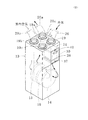
図1、図2に示すように、本発明の一実施の形態に係るデシカント式換気扇10は、室内の換気を行うためのものであり、室内に外気を取り込む給気路11と室内の空気を排出する排気路12がケーシング13内に形成され、給気路11と排気路12の相対湿度が高い側から低い側に水分を移動させるデシカントロータ14、15を有している。
そして、ケーシング13内には、給気路11を流れる外気と排気路12を流れる室内の空気の熱交換を行って、室内の温度変化を抑制するための熱交換器16が設けられている。
以下、これらについて詳細に説明する。
Next, embodiments of the present invention will be described with reference to the accompanying drawings for understanding of the present invention.
As shown in FIGS. 1 and 2, a desiccant-
In the
Hereinafter, these will be described in detail.
直方体形状のケーシング13内に形成された給気路11及び排気路12は、図1に示すように仕切板17を介して隣接され、ケーシング13内には、給気路11の外気(以下、「空気」ともいう)の出側と排気路12の空気の出側にそれぞれファン18、18aが設けられている。
図2に示すように、給気路11の空気の流入口を形成するダクト接続部材19には、一端部が屋外に配置されたダクト20の他端部が連結され、給気路11の空気の流出口を形成するダクト接続部材19aには、一端部が室内に配置されたダクト20aの他端部が連結されている。また、排気路12の空気の流入口を形成するダクト接続部材19bには、一端部が室内に配置されたダクト20bの他端部が連結され、排気路12の空気の流出口を形成するダクト接続部材19cには、一端部が屋外に配置されたダクト20cの他端部が連結されている。
The
As shown in FIG. 2, the
ファン18が作動すると、給気路11にはダクト20を介して外気が流入し、給気路11を通過した外気は、ダクト20aを通って室内に送られる。ファン18aが作動すると、室内の空気はダクト20b、排気路12及びダクト20cを通って屋外に排出される。ファン18、18aには、図1に示すように制御装置21が信号接続されており、制御装置21は信号出力によってファン18、18aを作動し、室内の空気の入れ替え、即ち室内の換気を行うことができる。
When the
また、ケーシング13内には、室内換気の際に室内の湿度を保つべく円盤状のデシカントロータ14、15が設けられている。デシカントロータ14、15には、シリカゲル等の吸湿材が付着されており、給気路11を流れる空気と排気路12を流れる空気において相対湿度が高い方の空気から水分を吸収して、相対湿度が低い方の空気にその吸収した水分を放出することができる。
デシカントロータ14、15は、仕切板17を貫通し、給気路11と排気路12を遮るように配置され、制御装置21からの信号出力によって駆動する図示しないモータの作動によって回転する。給気路11内の空気の流れは、排気路12内の空気の流れに対して反対向きになっており、デシカントロータ14は、給気路11の空気の流れを基準にしてデシカントロータ15の上流側に位置し、排気路12の空気の流れを基準にしてデシカントロータ15の下流側に位置している。
In addition, disc-
The
給気路11内には、デシカントロータ15に近接して加湿再生器22が設けられ、加湿再生器22は、加湿再生器22内を流れる高温高圧の熱媒の熱を熱源に給気路11を流れる空気を加熱することができる。加湿再生器22は、熱媒が循環する熱伝導性に優れた銅等によって形成された金属管と、アルミニウム等により形成され、熱伝導面積を広くするために設けられたフィンを有している。
室内の湿度低下を抑制しながら室内の換気を行う場合、制御装置21は、デシカントロータ14を停止した状態で、デシカントロータ15を回転すると共にファン18、18aを作動する。これにより、デシカントロータ15は、排気路12を流れる室内の空気から水分を吸収し、その水分を吸収した部分が給気路11に移動した際に加湿再生器22で加熱されて、給気路11を流れる外気に水分を与え、室内に湿気を含んだ外気を供給する。
A
When performing indoor ventilation while suppressing a decrease in indoor humidity, the
また、排気路12内には、デシカントロータ14に近接して除湿再生器23が設けられ、除湿再生器23は、除湿再生器23内を流れる高温高圧の熱媒の熱を熱源に排気路12を流れる空気を加熱することができる。除湿再生器23は、加湿再生器22と同様に熱媒が循環する熱伝導性に優れた銅等によって形成された金属管と、アルミニウム等により形成され、熱伝導面積を広くするために設けられたフィンを有している。
室内の湿度上昇を抑制しながら室内の換気を行う場合、制御装置21は、デシカントロータ15を停止した状態で、デシカントロータ14を回転すると共にファン18、18aを作動する。これにより、デシカントロータ14は、給気路11を流れる外気から水分を吸収し、その水分を吸収した部分が排気路12に移動した際に除湿再生器23で加熱されて、排気路12を流れる室内の空気に水分を放出し乾燥状態になる。
Further, a
When performing indoor ventilation while suppressing an increase in indoor humidity, the
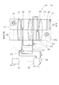
ケーシング13内には、加湿再生器22と除湿再生器23を接続する熱媒循環回路24が設けられ、熱媒循環回路24には、加湿再生器22及び除湿再生器23の他に、アキュムレータ25、圧縮機26、四方弁27及び膨張弁28が設けられている。
四方弁27は、制御装置21に信号接続されており、制御装置21からの信号出力によって、熱媒循環回路24を循環する熱媒の流れを切り替えて、加湿再生器22及び除湿再生器23のいずれか一方を凝縮器として機能させ、他方を蒸発器として機能させることができる。
In the
The four-
室内の湿度低下を抑制する加湿運転を行う場合、図3に示すように、四方弁27は加湿再生器22を凝縮器として機能させるべく、加湿再生器22に高温高圧の熱媒を供給するための熱媒の流れを熱媒循環回路24に形成する。具体的には、四方弁27の切り替えにより、圧縮機26で高温高圧となった熱媒が、四方弁27を通って加湿再生器22に送られ、加湿再生器22で凝縮(液化)して放熱した後、膨張弁28で低圧状態にされ、除湿再生器23に送られる。そして、低圧となった熱媒は、除湿再生器23で蒸発して排気路12を流れる室内の空気の熱を吸収し、四方弁27、アキュムレータ25を通過して圧縮機26で高圧状態にされる。
When performing a humidification operation that suppresses a decrease in indoor humidity, as shown in FIG. 3, the four-
一方で、室内の湿度上昇を抑制する除湿運転を行う場合、図4に示すように、四方弁27は除湿再生器23を凝縮器として機能させるべく、除湿再生器23に高温高圧の熱媒を供給するための熱媒の流れを熱媒循環回路24に形成する。具体的には、四方弁27の切り替えにより、圧縮機26で高温高圧となった熱媒が、四方弁27を通って除湿再生器23に送られ、除湿再生器23で凝縮して放熱した後、膨張弁28で低圧状態にされ、加湿再生器22に送られる。そして、低圧となった熱媒は、加湿再生器22で蒸発して給気路11を流れる外気の熱を吸収し、四方弁27、アキュムレータ25を通過して圧縮機26で高圧状態にされる。
On the other hand, when performing a dehumidifying operation that suppresses an increase in humidity in the room, as shown in FIG. 4, the four-
制御装置21は、四方弁27の切り替えに加えて、圧縮機26へ信号を出力し圧縮機26を駆動することによって、熱媒循環回路24に熱媒を循環させることや、膨張弁28への信号出力によって膨張弁28の絞り開度を調整することができる。制御装置21は、例えばマイクロコンピュータ等からなり、マイクロコンピュータには四方弁27の切り替え等を行うためのプログラムが搭載されている。
In addition to switching the four-
また、ケーシング13内には、図1、図2に示すように、仕切板17を貫通し、デシカントロータ14、15の間に配置された円盤状の熱交換器16が設けられている。熱交換器16は、給気路11と排気路12を遮るように配置され、制御装置21からの信号出力によって駆動する図示しないモータによって回転する。
熱交換器16は、熱交換器16を通過する空気から顕熱を吸収して空気の温度を低下させること及び熱交換器16を通過する空気に熱を発散して空気の温度を上昇させることができる。
Further, as shown in FIGS. 1 and 2, the
The
室内暖房時、熱交換器16は、排気路12を流れる温かい室内の空気から顕熱を吸収し、回転動作によりこの顕熱を吸収した部分が給気路11に移動した際に給気路11を流れる外気を加熱する。これにより、室内の暖房効果を損なうことなく室内を換気することができる。
一方で室内冷房時には、熱交換器16が、給気路11を流れる外気から顕熱を吸収して室内に流入する外気の温度を低下するので、冷房中の室内温度の上昇を抑制することができる。なお、熱交換器16の顕熱を吸収した部分は、熱交換器16の回転動作で排気路12に移動した際に排気路12を流れる室内の空気に熱を発散する。
During indoor heating, the
On the other hand, at the time of indoor cooling, the
また、給気路11には、図2、図5に示すように、外気の流れに沿ってデシカントロータ14の上流側に配置された集塵フィルタ30と、集塵フィルタ30の更に上流側に配置された袋状の虫取りフィルタ31とが設けられている。
集塵フィルタ30は、平面状のフィルタ材を複数回折って蛇腹状にした集塵部32と集塵部32の外側を囲む矩形又は正方形の枠体部33とを有し、枠体部33を給気路11に固定して、ケーシング13内に取り付けられる。
虫取りフィルタ31は、開口部34のある袋体35と、袋体35に連続して形成され、開口部34を囲む矩形又は正方形の枠体36とを有し、枠体36を給気路11に固定して、ケーシング13内に取り付けられる。
As shown in FIGS. 2 and 5, the
The
The
虫取りフィルタ31は集塵フィルタ30に比べて目が粗く、ダクト20を介して給気路11に入ってきた虫や埃や粒子径の大きな粉塵等は、虫取りフィルタ31の袋体35の内側で捕捉され、虫取りフィルタ31を通過した粒子径の小さな粉塵(バクテリアや花粉等)は、集塵フィルタ30によって捕捉される。
ここで、虫取りフィルタ31の袋体35は、粒径5μm以上(本実施の形態では5μm)のものが捕集可能で、虫を捕集することに加え、比較的粒径の大きな粗塵を捕捉する。なお、虫取りフィルタ31は袋状であるが、給気路11を流れる外気の風圧によって裂け等が発生しないよう製作されている。また、集塵フィルタ30の集塵部32は、粒径0.3μm以上(本実施の形態では1μm)のものが捕集可能で、粒子径の小さなものを捕捉する。
なお、虫取りフィルタ31の袋体35と集塵フィルタ30は、周知の不織布を材質としている。
The
Here, the
The
ケーシング13は、本実施の形態では高さ100〜220cmであり、集塵フィルタ30及び虫取りフィルタ31は、80〜180cmの高さ位置でケーシング13内に取り付けられており、通常の身長(例えば150〜180cm)の者が手に届く高さに配置されている。
また、集塵フィルタ30及び虫取りフィルタ31は、ケーシング13の一側に形成された取出口39を介してケーシング13内から取り出すことができ、その取出口39が設けられたケーシング13の一側から取り外し可能になっている。
取出口39には、留め具37でケーシング13に固定可能な蓋板材38を取り付けることができ、蓋板材38は、取出口39に取り付けられて取出口39を覆い、給気路11に取出口39を介して外気が流入しないようにしている。
また、蓋板材38には、作業者が手を引っ掛けることができる取っ手部材40が固定されているので、作業者は取出口39に取り付けられている蓋板材38を容易に取り外すことができる。
The
Further, the
A
Moreover, since the
集塵フィルタ30及び虫取りフィルタ31は、蓋板材38をケーシング13から取り外した状態で、ケーシング13から取り出すことが可能であり、新しい集塵フィルタ30及び虫取りフィルタ31と取り替えることができる。
虫取りフィルタ31で捕捉された虫は、給気路11内を流れる外気の風圧により枠体36の内側、即ち開口部34を通過して袋体35の内側に貯まるので、作業者は、枠体36を掴んで虫取りフィルタ31をケーシング13から引っ張り出すことによって虫に触れることなく、虫取りフィルタ31をケーシング13から取り出すことができる。
The
The insects captured by the
また、虫取りフィルタ31には、枠体36の対向する位置に折れ目41が設けられており、この折れ目41を基準にして枠体36を折り曲げる(本実施の形態では2つ折りにする)ことによって開口部34を閉じることができる。
従って、作業者は、虫取りフィルタ31をケーシング13から取り出した後に、枠体36を2つ折りにして開口部34を閉じることで袋体35の内側に捕集された虫に触れることなく虫取りフィルタ31を廃棄することが可能である。
なお、枠体の対向する位置に折り目を一つずつ設けることができる他、例えば、図5に丸枠の(イ)に示すように、枠体の対向する位置に配置された対となる折り目を2組設けて、その対となる折り目の各組を基準に折り曲げて虫取りフィルタの開口部を閉じるようにしてもよい。
Further, the
Therefore, the operator removes the
In addition, one crease can be provided at each opposing position of the frame body. For example, as shown in (a) of the round frame in FIG. 5, a pair of fold lines arranged at the opposing position of the
以上、本発明の実施の形態を説明したが、本発明は、上記した形態に限定されるものでなく、要旨を逸脱しない条件の変更等は全て本発明の適用範囲である。
例えば、蓋板材は、ねじ部材によって取出口に取り付けるようにしてもよい。また、デシカントロータを一つだけにして加湿運転、又は、除湿運転のいずれかの運転のみが可能なものにすることができる。
Although the embodiments of the present invention have been described above, the present invention is not limited to the above-described embodiments, and all changes in conditions and the like that do not depart from the gist are within the scope of the present invention.
For example, the lid plate material may be attached to the outlet by a screw member. In addition, only one desiccant rotor can be used to enable only the humidifying operation or the dehumidifying operation.
10:デシカント式換気扇、11:給気路、12:排気路、13:ケーシング、14、15:デシカントロータ、16:熱交換器、17:仕切板、18、18a:ファン、19、19a、19b、19c:ダクト接続部材、20、20a、20b、20c:ダクト、21:制御装置、22:加湿再生器、23:除湿再生器、24:熱媒循環回路、25:アキュムレータ、26:圧縮機、27:四方弁、28:膨張弁、30:集塵フィルタ、31:虫取りフィルタ、32:集塵部、33:枠体部、34:開口部、35:袋体、36:枠体、37:留め具、38:蓋板材、39:取出口、40:取っ手部材、41:折り目
10: Desiccant type exhaust fan, 11: Air supply path, 12: Exhaust path, 13: Casing, 14, 15: Desiccant rotor, 16: Heat exchanger, 17: Partition plate, 18, 18a: Fan, 19, 19a,
Claims (4)
前記給気路には、前記外気の流れに沿って前記デシカントロータの上流側に配置された集塵フィルタと、該集塵フィルタの更に上流側に配置され、開口部のある袋体を備える虫取りフィルタとが設けられ、該虫取りフィルタは該袋体の内側で虫を捕捉することを特徴とするデシカント式換気扇。 An air supply path for taking outside air into the room and an exhaust path for exhausting the indoor air are formed in the casing, and a desiccant rotor for moving moisture from a high relative humidity side to a low side of the air supply path and the exhaust path is provided. In the desiccant type exhaust fan
The air supply path includes a dust collection filter disposed upstream of the desiccant rotor along the flow of the outside air, and an insect provided with a bag body that is disposed further upstream of the dust collection filter and has an opening. A desiccant-type ventilation fan, wherein the insect trapping filter captures insects inside the bag body.
Priority Applications (1)
| Application Number | Priority Date | Filing Date | Title |
|---|---|---|---|
| JP2011025118A JP2012163283A (en) | 2011-02-08 | 2011-02-08 | Desiccant type ventilation fan |
Applications Claiming Priority (1)
| Application Number | Priority Date | Filing Date | Title |
|---|---|---|---|
| JP2011025118A JP2012163283A (en) | 2011-02-08 | 2011-02-08 | Desiccant type ventilation fan |
Publications (1)
| Publication Number | Publication Date |
|---|---|
| JP2012163283A true JP2012163283A (en) | 2012-08-30 |
Family
ID=46842836
Family Applications (1)
| Application Number | Title | Priority Date | Filing Date |
|---|---|---|---|
| JP2011025118A Pending JP2012163283A (en) | 2011-02-08 | 2011-02-08 | Desiccant type ventilation fan |
Country Status (1)
| Country | Link |
|---|---|
| JP (1) | JP2012163283A (en) |
Cited By (3)
| Publication number | Priority date | Publication date | Assignee | Title |
|---|---|---|---|---|
| CN103234248A (en) * | 2013-04-25 | 2013-08-07 | 西安工程大学 | Press-in type vertical pipe indirect-hydrodynamic force water spraying chamber composite type evaporative cooling air conditioner |
| CN103615773A (en) * | 2013-07-21 | 2014-03-05 | 叶立英 | Method and device for processing air through desiccant devices with desiccants capable of being regenerated at low temperature |
| WO2016045582A1 (en) * | 2014-09-23 | 2016-03-31 | 中国商用飞机有限责任公司 | Dewatering device for air conditioning system in aircraft |
Citations (9)
| Publication number | Priority date | Publication date | Assignee | Title |
|---|---|---|---|---|
| JPH05311771A (en) * | 1992-05-12 | 1993-11-22 | Natl House Ind Co Ltd | Under-floor air intake device |
| JPH08196491A (en) * | 1995-01-24 | 1996-08-06 | Hitachi Ltd | Vacuum cleaner |
| JPH11325535A (en) * | 1998-05-15 | 1999-11-26 | Topre Corp | Insect prevention structure for indoor ventilating structure |
| JP2001182960A (en) * | 1999-12-24 | 2001-07-06 | Sanyo Electric Co Ltd | Indoor unit of air conditioner |
| JP2009058188A (en) * | 2007-08-31 | 2009-03-19 | Toshiba Carrier Corp | Air conditioner |
| JP2009300019A (en) * | 2008-06-13 | 2009-12-24 | Mitsubishi Electric Corp | Heat exchange ventilating device |
| JP2010162419A (en) * | 2010-05-07 | 2010-07-29 | Mitsubishi Electric Corp | Vacuum cleaner |
| JP2011007362A (en) * | 2009-06-23 | 2011-01-13 | Chofu Seisakusho Co Ltd | Floor type desiccant ventilation fan |
| JP2011017522A (en) * | 2009-06-08 | 2011-01-27 | Chofu Seisakusho Co Ltd | Floor type heat exchange type ventilation fan |
-
2011
- 2011-02-08 JP JP2011025118A patent/JP2012163283A/en active Pending
Patent Citations (9)
| Publication number | Priority date | Publication date | Assignee | Title |
|---|---|---|---|---|
| JPH05311771A (en) * | 1992-05-12 | 1993-11-22 | Natl House Ind Co Ltd | Under-floor air intake device |
| JPH08196491A (en) * | 1995-01-24 | 1996-08-06 | Hitachi Ltd | Vacuum cleaner |
| JPH11325535A (en) * | 1998-05-15 | 1999-11-26 | Topre Corp | Insect prevention structure for indoor ventilating structure |
| JP2001182960A (en) * | 1999-12-24 | 2001-07-06 | Sanyo Electric Co Ltd | Indoor unit of air conditioner |
| JP2009058188A (en) * | 2007-08-31 | 2009-03-19 | Toshiba Carrier Corp | Air conditioner |
| JP2009300019A (en) * | 2008-06-13 | 2009-12-24 | Mitsubishi Electric Corp | Heat exchange ventilating device |
| JP2011017522A (en) * | 2009-06-08 | 2011-01-27 | Chofu Seisakusho Co Ltd | Floor type heat exchange type ventilation fan |
| JP2011007362A (en) * | 2009-06-23 | 2011-01-13 | Chofu Seisakusho Co Ltd | Floor type desiccant ventilation fan |
| JP2010162419A (en) * | 2010-05-07 | 2010-07-29 | Mitsubishi Electric Corp | Vacuum cleaner |
Cited By (4)
| Publication number | Priority date | Publication date | Assignee | Title |
|---|---|---|---|---|
| CN103234248A (en) * | 2013-04-25 | 2013-08-07 | 西安工程大学 | Press-in type vertical pipe indirect-hydrodynamic force water spraying chamber composite type evaporative cooling air conditioner |
| CN103615773A (en) * | 2013-07-21 | 2014-03-05 | 叶立英 | Method and device for processing air through desiccant devices with desiccants capable of being regenerated at low temperature |
| WO2016045582A1 (en) * | 2014-09-23 | 2016-03-31 | 中国商用飞机有限责任公司 | Dewatering device for air conditioning system in aircraft |
| US10773809B2 (en) | 2014-09-23 | 2020-09-15 | Commercial Aircraft Corporation Of China, Ltd | Dewatering device for an air conditioning system of a plane |
Similar Documents
| Publication | Publication Date | Title |
|---|---|---|
| KR20160100055A (en) | Dehumidifier | |
| CN104214842B (en) | With the air purifier of dehumidification function | |
| JP2011528426A (en) | Method and apparatus for adjusting air to be supplied indoors to desired temperature and desired humidity | |
| WO2017043104A1 (en) | Dehumidification and humidification device | |
| JP4306780B2 (en) | Humidity control device | |
| JP2012163283A (en) | Desiccant type ventilation fan | |
| JP2016114344A (en) | Air conditioner | |
| CN105605689B (en) | A kind of air processor and its control method | |
| JP2006090572A (en) | Air conditioner | |
| CN203518008U (en) | Dehumidification unit of air conditioner | |
| CN203719083U (en) | Air conditioner moisture storage and humidifying device as well as air conditioner indoor unit and air conditioner system adopting device | |
| JP5906708B2 (en) | Humidity control device | |
| JP7150493B2 (en) | air conditioner | |
| CN205825281U (en) | There is the air cleaning system of air-conditioning device | |
| JP6563287B2 (en) | Dehumidifying / humidifying device | |
| CN106016524A (en) | Air purification system with air-conditioning device | |
| CN206387001U (en) | The permanent net wall indoor unit of the permanent oxygen of ultra-thin constant temperature and humidity | |
| CN205825295U (en) | Primary and secondary air is with the indirect evaporative cooling cooling system of air inlet | |
| WO2021039149A1 (en) | Heat exchange-type ventilation device equipped with dehumidifying function | |
| CN215216503U (en) | Take humidity control's new fan of constant temperature | |
| JP2019098201A (en) | Dehumidifier | |
| JP2017127823A (en) | Bug capturing filter and ventilation device including the same | |
| KR102384598B1 (en) | Constant temperature dehumidification and drying apparatus | |
| CN208238207U (en) | A kind of air conditioner with condensation effect | |
| JP2024002401A (en) | Dehumidification device |
Legal Events
| Date | Code | Title | Description |
|---|---|---|---|
| A621 | Written request for application examination |
Free format text: JAPANESE INTERMEDIATE CODE: A621 Effective date: 20140204 |
|
| A977 | Report on retrieval |
Free format text: JAPANESE INTERMEDIATE CODE: A971007 Effective date: 20140611 |
|
| A131 | Notification of reasons for refusal |
Free format text: JAPANESE INTERMEDIATE CODE: A131 Effective date: 20140617 |
|
| A521 | Written amendment |
Free format text: JAPANESE INTERMEDIATE CODE: A523 Effective date: 20140910 |
|
| A131 | Notification of reasons for refusal |
Free format text: JAPANESE INTERMEDIATE CODE: A131 Effective date: 20141104 |
|
| A02 | Decision of refusal |
Free format text: JAPANESE INTERMEDIATE CODE: A02 Effective date: 20150407 |