JP2012163192A - Rotating body holding mechanism - Google Patents
Rotating body holding mechanism Download PDFInfo
- Publication number
- JP2012163192A JP2012163192A JP2011026171A JP2011026171A JP2012163192A JP 2012163192 A JP2012163192 A JP 2012163192A JP 2011026171 A JP2011026171 A JP 2011026171A JP 2011026171 A JP2011026171 A JP 2011026171A JP 2012163192 A JP2012163192 A JP 2012163192A
- Authority
- JP
- Japan
- Prior art keywords
- rotating body
- holding mechanism
- body holding
- groove
- lubricant
- Prior art date
- Legal status (The legal status is an assumption and is not a legal conclusion. Google has not performed a legal analysis and makes no representation as to the accuracy of the status listed.)
- Pending
Links
Images


Abstract
Description
本発明は、回転体の保持機構に関する。 The present invention relates to a rotating body holding mechanism.
駆動装置において、ギヤ等の回転体と保持軸との摩擦抵抗を長期間にわたって低減すべく、回転体と軸受部との接触領域に潤滑剤を供給する目的で潤滑剤が保持される保持溝を備え、保持溝より回転体の回転に伴って回転体に対して潤滑剤が供給される技術が、例えば「特許文献1」に開示されている。
In the drive device, in order to reduce the frictional resistance between the rotating body such as a gear and the holding shaft over a long period of time, a holding groove for holding the lubricant is provided for the purpose of supplying the lubricant to the contact area between the rotating body and the bearing portion. A technique in which a lubricant is supplied from a holding groove to a rotating body as the rotating body rotates is disclosed in, for example, “
「特許文献1」に開示された技術では、潤滑剤と回転体とが接触しなくなったときに保持溝内に蓄えられた潤滑剤が回転体に供給されず、保持溝内に潤滑剤が残存してしまうという問題点がある。
In the technique disclosed in “
本発明は上述した問題を解決し、保持溝内に残存した潤滑剤を回転体に供給することが可能な回転体保持機構の提供を目的とする。 An object of the present invention is to provide a rotating body holding mechanism that solves the above-described problems and can supply the lubricant remaining in the holding groove to the rotating body.
請求項1記載の発明は、保持部材により固定保持され水平方向に延在する軸部材と、前記軸部材に回転自在に支持された回転体と、前記軸部材の径方向下側に設けられた溝部と、前記溝部に充填され前記回転体と前記軸部材との間に供給される潤滑剤とを有する回転体保持機構において、前記溝部内に配設され、前記回転体の回転時に回転可能な棒状の潤滑剤供給部材を有することを特徴とする。
The invention according to
請求項2記載の発明は、請求項1記載の回転体保持機構において、さらに前記回転体は前記軸部材との間に片当たり部を有し、該片当たり部と対応する位置に前記潤滑剤供給部材を有することを特徴とする。 According to a second aspect of the present invention, in the rotating body holding mechanism according to the first aspect, the rotating body further includes a piece contact portion between the rotating member and the shaft member, and the lubricant is located at a position corresponding to the piece contact portion. It has a supply member, It is characterized by the above-mentioned.
請求項3記載の発明は、請求項1または2記載の回転体保持機構において、さらに前記潤滑剤供給部材は正逆回転可能であることを特徴とする。 According to a third aspect of the present invention, in the rotating body holding mechanism according to the first or second aspect, the lubricant supply member is further rotatable forward and backward.
請求項4記載の発明は、請求項1ないし3の何れか1つに記載の回転体保持機構において、さらに前記溝部は前記軸部材に形成された平面部により構成されていることを特徴とする。 According to a fourth aspect of the present invention, in the rotating body holding mechanism according to any one of the first to third aspects, the groove portion is further configured by a flat portion formed in the shaft member. .
請求項5記載の発明は、請求項1ないし3の何れか1つに記載の回転体保持機構において、さらに前記溝部はその開口の幅が前記潤滑剤供給部材の直径よりも小さくなるように形成されていることを特徴とする。 According to a fifth aspect of the present invention, in the rotating body holding mechanism according to any one of the first to third aspects, the groove portion is formed such that the width of the opening is smaller than the diameter of the lubricant supply member. It is characterized by being.
請求項6記載の発明は、請求項1ないし3の何れか1つに記載の回転体保持機構において、さらに前記溝部は断面矩形状であってその底部角部がそれぞれ円弧状となるように形成され、前記円弧状角部はその円弧の半径が前記潤滑剤供給部材の半径以上となるように形成されていることを特徴とする。 According to a sixth aspect of the present invention, in the rotating body holding mechanism according to any one of the first to third aspects, the groove portion is formed in a rectangular shape in cross section, and a bottom corner portion thereof is formed in an arc shape. The arcuate corner is characterized in that the radius of the arc is greater than or equal to the radius of the lubricant supply member.
請求項7記載の発明は、請求項1ないし3の何れか1つに記載の回転体保持機構において、さらに前記溝部は前記軸部材の自由端に達しないように形成されていることを特徴とする。 A seventh aspect of the present invention is the rotating body holding mechanism according to any one of the first to third aspects, wherein the groove portion is formed so as not to reach a free end of the shaft member. To do.
請求項8記載の発明は、請求項1ないし3の何れか1つに記載の回転体保持機構において、さらに前記溝部は前記軸部材の固定端に達しないように形成されていることを特徴とする。 According to an eighth aspect of the present invention, in the rotating body holding mechanism according to any one of the first to third aspects, the groove portion is formed so as not to reach a fixed end of the shaft member. To do.
請求項9記載の発明は、請求項1ないし8の何れか1つに記載の回転体保持機構において、さらに前記潤滑剤供給部材が金属製であることを特徴とする。 According to a ninth aspect of the present invention, in the rotating body holding mechanism according to any one of the first to eighth aspects, the lubricant supply member is made of metal.
請求項10記載の発明は、請求項1ないし9の何れか1つに記載の回転体保持機構において、さらに前記潤滑剤供給部材がばね形状を呈していることを特徴とする。 According to a tenth aspect of the present invention, in the rotating body holding mechanism according to any one of the first to ninth aspects, the lubricant supply member further has a spring shape.
請求項11記載の発明は、請求項1ないし10の何れか1つに記載の回転体保持機構において、さらに前記回転体がギヤであることを特徴とする。 According to an eleventh aspect of the present invention, in the rotating body holding mechanism according to any one of the first to tenth aspects, the rotating body is a gear.
請求項12記載の発明は、請求項1ないし10の何れか1つに記載の回転体保持機構において、さらに前記回転体がプーリであることを特徴とする。 According to a twelfth aspect of the present invention, in the rotating body holding mechanism according to any one of the first to tenth aspects, the rotating body is a pulley.
本発明によれば、溝部内に配置され回転体の摺動面に接触する潤滑剤供給部材が回転体の回転に伴い断続的または連続的に回転し、この潤滑剤供給部材の回転により溝部内に充填されている潤滑剤が徐々に掻き出されて回転体の摺動面に供給されることで溝部内に充填された潤滑剤を有効に活用することができ、短期間毎に潤滑剤を充填する必要がなくなり作業効率を向上させることができる。 According to the present invention, the lubricant supply member disposed in the groove and contacting the sliding surface of the rotating body rotates intermittently or continuously with the rotation of the rotating body, and the rotation of the lubricant supplying member causes the inside of the groove to The lubricant filled in is gradually scraped out and supplied to the sliding surface of the rotating body, so that the lubricant filled in the groove can be used effectively. It is not necessary to fill, and work efficiency can be improved.
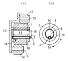
図1は、本発明の一実施形態を適用可能な駆動力伝達装置における回転体保持機構を示している。同図において、垂直に配置された保持部材5は図示しない不動部材に固定されており、保持部材5には水平方向に延在する軸部材である軸2が固定支持されている。軸2の上方には軸7が水平方向に延在する態様で保持部材5に固定支持されており、軸2の下方には同様に軸9が保持部材5に固定支持されている。軸2には回転体1が、軸7には回転体6が、軸9には回転体8がそれぞれ回転自在に支持されており、回転体6から入力された回転力が回転体1を介して回転体8に伝達されるように、各回転体1,6,8が接続されている。
FIG. 1 shows a rotating body holding mechanism in a driving force transmission device to which an embodiment of the present invention can be applied. In the figure, a vertically arranged holding
軸2には断面矩形状の溝部4が軸2の固定端から自由端にわたって形成されており、溝部4内には軸2と回転体1との間の摩擦抵抗力を低減させるための潤滑剤3が充填されている。この構成により、回転体1が回転すると溝部4内の潤滑剤3が回転体1と軸2との間に供給され、回転体1と軸2との間の摩擦抵抗力が低減される。
A
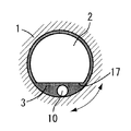
しかし上述の構成では、回転体1が所定期間回転して溝部4内の潤滑剤3が少なくなると、図2に示すように溝部4内から潤滑剤3が供給されず、溝部4内に潤滑剤3が残存しているにも拘わらず回転体1と軸2との間の摩擦抵抗力が増大し、駆動力伝達装置としての機能が低下してしまい最悪の場合には軸2に対して回転体1が焼き付いてしまう。このような不具合の発生を防止するためには、溝部4内に対して短期間毎に潤滑剤3を充填することが必要となるが、作業効率が極端に悪化してしまう。
However, in the above-described configuration, when the
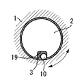
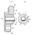
上述の問題点を解決すべく、本発明では図3に示す構成を採用している。なお、図3において図1と同じ部位には同じ符号を付すに止め、その詳細な説明は省略する。図3に示す本発明の第1の実施形態において、溝部4の内部には潤滑剤3が充填されていると共に潤滑剤供給部材10が配設されている。金属製の棒状体からなる潤滑剤供給部材10はその直径が溝部4の幅及び深さよりも小さくなるように形成されており、溝部4内に配置されて回転体1が軸2に支持された際に、図3及び図4に示すように回転体1の摺動面によって落下しないように支持される。
In order to solve the above-described problems, the present invention employs the configuration shown in FIG. In FIG. 3, the same parts as those in FIG. 1 are given the same reference numerals, and detailed description thereof is omitted. In the first embodiment of the present invention shown in FIG. 3, the
上述の構成により、溝部4内に配置され自重により回転体1の摺動面に接触する潤滑剤供給部材10が回転体1の回転に伴い断続的または連続的に回転し、この潤滑剤供給部材10の回転により溝部4内に充填されている潤滑剤3が徐々に掻き出されて回転体1の摺動面に供給されることで溝部4内に充填された潤滑剤3を有効に活用することができ、短期間毎に潤滑剤3を充填する必要がなくなり作業効率を向上させることができる。
With the above-described configuration, the
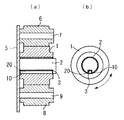
図5は、本発明の第2の実施形態を示している。この第2の実施形態は第1の実施形態と比較すると、保持部材5に代えて段差部を有する保持部材11を用いる点、回転体6及び軸7に代えて回転体6及び軸7よりも長さの短い回転体12及び軸13を用いる点、回転体8及び軸9に代えて回転体8及び軸9よりも長さの短い回転体14及び軸15を用いる点において相違している。この構成より、回転体12から入力された回転力が回転体1を介して回転体14に伝達されるが、回転体12と回転体1との間及び回転体1と回転体14との間には、図7において符号16で示す2箇所の片当たり部が生じることとなる。ここで、第2の実施形態における潤滑剤供給部材10は、各片当たり部16と対応する位置に配置、すなわち各片当たり部16の固定端側から自由端側までの長さL以上の長さL1となるように形成されている。
FIG. 5 shows a second embodiment of the present invention. Compared with the first embodiment, the second embodiment uses a
上述の構成により、回転体1と軸2との間に複数の片当たり部が存在していても、各片当たり部と対応する位置に配置された潤滑剤供給部材10が回転体1の回転に伴い溝部4内から回転体1と軸2との間に潤滑剤3を供給するので、溝部4内に充填された潤滑剤3を有効に活用することができ、短期間毎に潤滑剤3を充填する必要がなくなり作業効率を向上させることができる。
With the above-described configuration, even if there are a plurality of piece contact portions between the
図6は、本発明の第3の実施形態を示している。この第3の実施形態は第1の実施形態と比較すると、溝部4に代えて軸部2の一部に平面部17を形成してここに潤滑剤3を充填すると共に、平面部17と回転体1の摺動面との間に潤滑剤供給部材10を設けている点において相違している。これにより第1の実施形態と同様の作用効果を奏すると共に、溝部4に比して平面部17は加工が容易であるので加工工程を低減することができる。
FIG. 6 shows a third embodiment of the present invention. Compared with the first embodiment, the third embodiment forms a
図7は、本発明の第4の実施形態を示している。この第4の実施形態は第1の実施形態と比較すると、溝部4に代えて開口の幅が潤滑剤供給部材10の直径よりも小さくなるように形成された溝部18を軸2に形成し、溝部18内に潤滑剤3を充填すると共に溝部18内に潤滑剤供給部材10を設けている点において相違している。これにより第1の実施形態と同様の作用効果を奏すると共に、潤滑剤供給部材10が溝部18内より下方へと落下しないことから、組付けを容易化することにより工数低減を図ることができる。
FIG. 7 shows a fourth embodiment of the present invention. Compared with the first embodiment, the fourth embodiment forms a
図8は、本発明の第5の実施形態を示している。この第5の実施形態は第1の実施形態と比較すると、溝部4に代えて断面矩形状であってその底部角部がそれぞれ円弧状となるように形成された溝部19を軸2に形成し、溝部19内に潤滑剤3を充填すると共に溝部19内に潤滑剤供給部材10を設けている点において相違している。溝部19の各円弧状角部は、それぞれの円弧の半径が潤滑剤供給部材10の半径以上となるように形成されている。これにより第1の実施形態と同様の作用効果を奏すると共に、潤滑剤供給部材10が溝部19内より潤滑剤3を掻き出す機能を、溝部4の場合に比して向上させることができる。
FIG. 8 shows a fifth embodiment of the present invention. Compared with the first embodiment, the fifth embodiment is formed by forming a
図9は、本発明の第6の実施形態を示している。この第6の実施形態は第1の実施形態と比較すると、溝部4に代えてその端部が軸2の自由端に達しないように形成された溝部20を軸2に形成し、溝部20内に潤滑剤3を充填すると共に溝部20内に潤滑剤供給部材10を設けている点において相違している。これにより第1の実施形態と同様の作用効果を奏すると共に、潤滑剤供給部材10が軸方向に移動して軸2より落下してしまうことを防止することができる。なお、この構成は上述した第2ないし第5の実施形態に対しても適用可能である。
FIG. 9 shows a sixth embodiment of the present invention. Compared with the first embodiment, the sixth embodiment forms a
図10は、本発明の第7の実施形態を示している。この第7の実施形態は第1の実施形態と比較すると、溝部4に代えてその端部が軸2の固定端に達しないように形成された溝部21を軸2に形成し、溝部21内に潤滑剤3を充填すると共に溝部21内に潤滑剤供給部材10を設けている点において相違している。これにより第1の実施形態と同様の作用効果を奏すると共に、回転体1における軸2の固定端側の内周面が軸2と接触しない場合に、溝部21内に充填する潤滑剤3の量を溝部4の場合に比して低減することが可能となる。この構成も上述した第2ないし第6の実施形態に対して適用可能である。
FIG. 10 shows a seventh embodiment of the present invention. Compared with the first embodiment, the seventh embodiment forms a
図11は、上述した第2の実施形態において、回転体1に代えてギヤ22を、回転体12に代えてギヤ23を、回転体14に代えてギヤ24をそれぞれ用いた例を示している。この構成により、ギヤ23より入力された回転力によりギヤ23と噛合するギヤ22が回転し、ギヤ22が回転することによりギヤ22と噛合するギヤ24が回転する。このギヤ22の回転時において、ギヤ22の回転に伴い潤滑剤供給部材10が連続的または断続的に回転し、溝部4内に充填された潤滑剤3がギヤ22の摺動面と軸2との間に効率的に供給される。
FIG. 11 shows an example in which the
図12は、上述した第1の実施形態において、回転体1に代えてプーリ25を用い、プーリ25に無端ベルト26を掛け回した例を示している。この構成により、無端ベルト26より入力された回転力によりプーリ25が回転し、この回転時においてプーリ25の回転に伴い潤滑剤供給部材が連続的または断続的に回転し、溝部4内に充填された潤滑剤3がギヤプーリ25の摺動面と軸2との間に効率的に供給される。
FIG. 12 shows an example in which the
上述した各実施形態において、回転体1の回転方向は正転及び逆転の何れであってもよく、回転体1の回転方向に応じて潤滑剤供給部材10が回転体1と同方向に回転して潤滑剤3を供給する。また、上記各実施形態では潤滑剤供給部材10として金属製の棒状のものを示したが、潤滑剤供給部材としてばね形状のもの(例えば金属製の圧縮ばね等)を用いてもよい。これにより潤滑剤供給部材が棒状の場合に比して多くの潤滑剤3を保持することができ、潤滑剤3の供給効率を向上することができる。
In each embodiment described above, the rotating direction of the
本発明で示した回転体保持機構は、上述したギヤ及びプーリには限られず他の回転体に対しても適用可能であり、プリンタ、複写機、プロッタ、印刷装置等の画像形成装置の各種機構部に対しても適用可能である。 The rotating body holding mechanism shown in the present invention is not limited to the gears and pulleys described above, and can be applied to other rotating bodies. Various mechanisms of image forming apparatuses such as printers, copying machines, plotters, and printing apparatuses It can also be applied to parts.
1 回転体
2 軸部材(軸)
3 潤滑剤
4,18.19.20.21 溝部
5,11 保持部材
16 片当たり部
17 平面部
22 ギヤ
25 プーリ
1 Rotating
3
Claims (12)
前記溝部内に配設され、前記回転体の回転時に回転可能な棒状の潤滑剤供給部材を有することを特徴とする回転体保持機構。 A shaft member fixed and held by a holding member and extending in the horizontal direction, a rotating body rotatably supported by the shaft member, a groove provided on the lower side in the radial direction of the shaft member, and the groove filled. In a rotating body holding mechanism having a lubricant supplied between the rotating body and the shaft member,
A rotating body holding mechanism, comprising: a rod-like lubricant supply member that is disposed in the groove and is rotatable when the rotating body is rotated.
前記回転体は前記軸部材との間に片当たり部を有し、該片当たり部と対応する位置に前記潤滑剤供給部材を有することを特徴とする回転体保持機構。 The rotating body holding mechanism according to claim 1,
The rotator has a piece contact portion with the shaft member, and has the lubricant supply member at a position corresponding to the piece contact portion.
前記潤滑剤供給部材は正逆回転可能であることを特徴とする回転体保持機構。 The rotating body holding mechanism according to claim 1 or 2,
The rotating body holding mechanism is characterized in that the lubricant supply member can rotate forward and backward.
前記溝部は前記軸部材に形成された平面部により構成されていることを特徴とする回転体保持機構。 The rotating body holding mechanism according to any one of claims 1 to 3,
The rotating body holding mechanism according to claim 1, wherein the groove portion is constituted by a flat portion formed on the shaft member.
前記溝部はその開口の幅が前記潤滑剤供給部材の直径よりも小さくなるように形成されていることを特徴とする回転体保持機構。 The rotating body holding mechanism according to any one of claims 1 to 3,
The rotary member holding mechanism, wherein the groove portion is formed so that the width of the opening is smaller than the diameter of the lubricant supply member.
前記溝部は断面矩形状であってその底部角部がそれぞれ円弧状となるように形成され、前記円弧状角部はその円弧の半径が前記潤滑剤供給部材の半径以上となるように形成されていることを特徴とする回転体保持機構。 The rotating body holding mechanism according to any one of claims 1 to 3,
The groove has a rectangular cross section and is formed such that the bottom corners are arcuate, and the arcuate corner is formed such that the radius of the arc is equal to or greater than the radius of the lubricant supply member. A rotating body holding mechanism.
前記溝部は前記軸部材の自由端に達しないように形成されていることを特徴とする回転体保持機構。 The rotating body holding mechanism according to any one of claims 1 to 3,
The rotating body holding mechanism, wherein the groove is formed so as not to reach a free end of the shaft member.
前記溝部は前記軸部材の固定端に達しないように形成されていることを特徴とする回転体保持機構。 The rotating body holding mechanism according to any one of claims 1 to 3,
The rotating body holding mechanism, wherein the groove is formed so as not to reach a fixed end of the shaft member.
前記潤滑剤供給部材が金属製であることを特徴とする回転体保持機構。 The rotating body holding mechanism according to any one of claims 1 to 8,
The rotating body holding mechanism, wherein the lubricant supply member is made of metal.
前記潤滑剤供給部材がばね形状を呈していることを特徴とする回転体保持機構。 The rotating body holding mechanism according to any one of claims 1 to 9,
The rotating body holding mechanism, wherein the lubricant supply member has a spring shape.
前記回転体がギヤであることを特徴とする回転体保持機構。 The rotating body holding mechanism according to any one of claims 1 to 10,
The rotating body holding mechanism, wherein the rotating body is a gear.
前記回転体がプーリであることを特徴とする回転体保持機構。 The rotating body holding mechanism according to any one of claims 1 to 10,
The rotating body holding mechanism, wherein the rotating body is a pulley.
Priority Applications (1)
| Application Number | Priority Date | Filing Date | Title |
|---|---|---|---|
| JP2011026171A JP2012163192A (en) | 2011-02-09 | 2011-02-09 | Rotating body holding mechanism |
Applications Claiming Priority (1)
| Application Number | Priority Date | Filing Date | Title |
|---|---|---|---|
| JP2011026171A JP2012163192A (en) | 2011-02-09 | 2011-02-09 | Rotating body holding mechanism |
Publications (1)
| Publication Number | Publication Date |
|---|---|
| JP2012163192A true JP2012163192A (en) | 2012-08-30 |
Family
ID=46842765
Family Applications (1)
| Application Number | Title | Priority Date | Filing Date |
|---|---|---|---|
| JP2011026171A Pending JP2012163192A (en) | 2011-02-09 | 2011-02-09 | Rotating body holding mechanism |
Country Status (1)
| Country | Link |
|---|---|
| JP (1) | JP2012163192A (en) |
Cited By (1)
| Publication number | Priority date | Publication date | Assignee | Title |
|---|---|---|---|---|
| JP2015132711A (en) * | 2014-01-14 | 2015-07-23 | キヤノン株式会社 | Drive transmission device and image forming apparatus |
Citations (1)
| Publication number | Priority date | Publication date | Assignee | Title |
|---|---|---|---|---|
| JPS61193231U (en) * | 1985-05-23 | 1986-12-01 |
-
2011
- 2011-02-09 JP JP2011026171A patent/JP2012163192A/en active Pending
Patent Citations (1)
| Publication number | Priority date | Publication date | Assignee | Title |
|---|---|---|---|---|
| JPS61193231U (en) * | 1985-05-23 | 1986-12-01 |
Cited By (2)
| Publication number | Priority date | Publication date | Assignee | Title |
|---|---|---|---|---|
| JP2015132711A (en) * | 2014-01-14 | 2015-07-23 | キヤノン株式会社 | Drive transmission device and image forming apparatus |
| US9411285B2 (en) | 2014-01-14 | 2016-08-09 | Canon Kabushiki Kaisha | Drive transmission device and image forming apparatus |
Similar Documents
| Publication | Publication Date | Title |
|---|---|---|
| JP6177327B2 (en) | Wave gear device | |
| JP5822817B2 (en) | Wheel drive device | |
| JP2014105749A (en) | Planetary gear device | |
| JP6608674B2 (en) | Roller gear cam mechanism | |
| JP6644447B2 (en) | Flat type wave gear device | |
| EP2119941A4 (en) | Gear device | |
| WO2017073693A1 (en) | Gear transmission | |
| JP2012163192A (en) | Rotating body holding mechanism | |
| JP2007187234A (en) | Oil seal | |
| JP2019158142A (en) | Gear unit | |
| CN210423607U (en) | Three-gear gearbox of scraping roller machine | |
| JP6517041B2 (en) | Reduction gear | |
| JP5086982B2 (en) | Planetary roller type power transmission device | |
| JP2012137113A (en) | Shaft device | |
| JP6122786B2 (en) | Lubrication structure of differential equipment | |
| JP2010216640A (en) | Pinion assembly | |
| JP6332106B2 (en) | Ravigneaux type planetary gear unit | |
| JP6333148B2 (en) | Eccentric oscillation type speed reducer and its crankshaft assembling method | |
| KR101939403B1 (en) | Planetary gear device and Wind turbine including the same | |
| JP2005076810A (en) | Retainer for needle bearing and needle bearing | |
| JP5606587B2 (en) | Gear device | |
| JP2011153656A (en) | Gear transmission lubricating equipment | |
| JP2010216591A (en) | Reduction gear | |
| JP2007120616A (en) | Planetary gear lubricating device of planetary gear decelerator | |
| JP6479741B2 (en) | Gear device |
Legal Events
| Date | Code | Title | Description |
|---|---|---|---|
| A621 | Written request for application examination |
Free format text: JAPANESE INTERMEDIATE CODE: A621 Effective date: 20140116 |
|
| A977 | Report on retrieval |
Free format text: JAPANESE INTERMEDIATE CODE: A971007 Effective date: 20140730 |
|
| A131 | Notification of reasons for refusal |
Free format text: JAPANESE INTERMEDIATE CODE: A131 Effective date: 20140805 |
|
| A521 | Written amendment |
Free format text: JAPANESE INTERMEDIATE CODE: A523 Effective date: 20140930 |
|
| A02 | Decision of refusal |
Free format text: JAPANESE INTERMEDIATE CODE: A02 Effective date: 20141202 |