JP2012157868A5 - - Google Patents
Download PDFInfo
- Publication number
- JP2012157868A5 JP2012157868A5 JP2011017342A JP2011017342A JP2012157868A5 JP 2012157868 A5 JP2012157868 A5 JP 2012157868A5 JP 2011017342 A JP2011017342 A JP 2011017342A JP 2011017342 A JP2011017342 A JP 2011017342A JP 2012157868 A5 JP2012157868 A5 JP 2012157868A5
- Authority
- JP
- Japan
- Prior art keywords
- hole
- cooling water
- tip
- chip
- nozzle
- Prior art date
- Legal status (The legal status is an assumption and is not a legal conclusion. Google has not performed a legal analysis and makes no representation as to the accuracy of the status listed.)
- Granted
Links
Images
Description
そこで本発明者等は、安定したアークで高温割れやアンダーカットのない高速溶接を実現することができるインサートチップおよびこれを用いるプラズマトーチを提供した。 Accordingly, the present inventors have provided an insert tip capable of realizing high-speed welding without hot cracking or undercut with a stable arc, and a plasma torch using the insert tip.
そこで本発明者等は、安定したアークで高温割れやアンダーカットのない溶接をより高速で行うことができる、冷却能力が高いインサートチップを提供した(特許文献6)。このインサートチップは、2個の電極配置空間と、各電極配置空間にそれぞれが連通する2個のノズルおよび該2個のノズルの中間点で該2個のノズルが分布する平面に対して交差する平面にあって冷却水が折り返すV型の冷却水流路を備える。これにより、チップ先端面(母材対向面)近くで冷却水が円滑に折返し、局所的に水あるいは泡が滞留することはなく、チップの冷却能力が高い。チップ端面に対して斜めにしかも先端部で交わるように穴開けすることでV型の冷却水流路を安価に形成できる。よって、溶接電力を大きくしてより高速に溶接を行うことができる。特許文献6にはさらに、チップ基体に1対のノズル部材を着脱可に結合したインサートチップも提示した。これによれば、高熱によりノズル部材の下端のノズル部分が変形又は熔損したとき、該ノズル部材を新品と取り替えて、チップ基体はそのまま使用して、メンテナンスコストを安くすることができる。 Accordingly, the present inventors have provided an insert tip having a high cooling capability that can perform welding without a high-temperature crack or undercut with a stable arc at a higher speed (Patent Document 6). This insert tip intersects two electrode arrangement spaces, two nozzles respectively communicating with each electrode arrangement space, and a plane in which the two nozzles are distributed at an intermediate point between the two nozzles. A V-shaped cooling water flow path is provided which is flat and the cooling water is turned back. Thereby, the cooling water smoothly turns back near the tip end surface (base material facing surface), the water or bubbles do not stay locally, and the chip cooling ability is high. A V-shaped cooling water flow path can be formed at low cost by making a hole obliquely with respect to the end surface of the chip and intersecting at the tip. Therefore, welding can be performed at higher speed by increasing the welding power. Patent Document 6 also presented an insert chip in which a pair of nozzle members are detachably coupled to a chip base. According to this, when the nozzle part at the lower end of the nozzle member is deformed or damaged by high heat, the nozzle member can be replaced with a new one, and the chip base can be used as it is, so that the maintenance cost can be reduced.
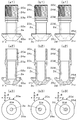
チップ基体1には、各ノズル部材の前記雄ねじ部から幹部までが挿通する各ノズル部材挿入穴18a,18b,各ノズル部材挿入穴に挿通した各ノズル部材の笠部が先端平面1d,1eに当接することにより閉じられる、ノズル部材挿入穴の一部をなし幹部との間に冷却水通流空間を形成する冷却水循環穴1f,1g,水受穴1h(図4),水出穴1i,隣り合う冷却水循環穴をつなぐ横通水穴1j,冷却水循環穴1fを水受穴1hにつなぐ横通水穴1k、および、冷却水循環穴1gを水出穴1iにつなぐ横通水穴1lがある。 In the chip base 1, the nozzle member insertion holes 18a and 18b through which the male threaded portion to the trunk portion of the nozzle members are inserted, and the cap portions of the nozzle members inserted through the nozzle member insertion holes contact the tip planes 1d and 1e. Cooling water circulation holes 1f, 1g, water receiving holes 1h (FIG. 4) , water outlet holes 1i, which form part of the nozzle member insertion hole and form a cooling water flow space with the trunk, which are closed by contact . There are a lateral water hole 1j that connects the matching cooling water circulation holes, a horizontal water hole 1k that connects the cooling water circulation hole 1f to the water receiving hole 1h, and a horizontal water hole 1l that connects the cooling water circulation hole 1g to the water outlet hole 1i.
Priority Applications (4)
| Application Number | Priority Date | Filing Date | Title |
|---|---|---|---|
| JP2011017342A JP5626994B2 (en) | 2011-01-30 | 2011-01-30 | Insert tip and plasma torch |
| TW100128807A TWI483653B (en) | 2011-01-30 | 2011-08-12 | Insert-chip and plasma torch |
| KR1020110100042A KR101311042B1 (en) | 2011-01-30 | 2011-09-30 | Insert-chip and plasma torch |
| CN201210031184.9A CN102615408B (en) | 2011-01-30 | 2012-01-20 | Plug-in chip and plasma gun |
Applications Claiming Priority (1)
| Application Number | Priority Date | Filing Date | Title |
|---|---|---|---|
| JP2011017342A JP5626994B2 (en) | 2011-01-30 | 2011-01-30 | Insert tip and plasma torch |
Publications (3)
| Publication Number | Publication Date |
|---|---|
| JP2012157868A JP2012157868A (en) | 2012-08-23 |
| JP2012157868A5 true JP2012157868A5 (en) | 2013-07-04 |
| JP5626994B2 JP5626994B2 (en) | 2014-11-19 |
Family
ID=46555802
Family Applications (1)
| Application Number | Title | Priority Date | Filing Date |
|---|---|---|---|
| JP2011017342A Active JP5626994B2 (en) | 2011-01-30 | 2011-01-30 | Insert tip and plasma torch |
Country Status (4)
| Country | Link |
|---|---|
| JP (1) | JP5626994B2 (en) |
| KR (1) | KR101311042B1 (en) |
| CN (1) | CN102615408B (en) |
| TW (1) | TWI483653B (en) |
Families Citing this family (3)
| Publication number | Priority date | Publication date | Assignee | Title |
|---|---|---|---|---|
| JP5796847B2 (en) * | 2012-03-08 | 2015-10-21 | 日鐵住金溶接工業株式会社 | Insert tip and plasma torch |
| JP6214048B2 (en) * | 2013-12-06 | 2017-10-18 | 日鐵住金溶接工業株式会社 | Multi-electrode welding torch |
| CN114411086A (en) * | 2021-12-23 | 2022-04-29 | 南京威登等离子科技设备有限公司 | Multi-nozzle plasma surface treatment equipment |
Family Cites Families (16)
| Publication number | Priority date | Publication date | Assignee | Title |
|---|---|---|---|---|
| US2756311A (en) * | 1954-03-24 | 1956-07-24 | Union Carbide & Carbon Corp | High-speed tandem arc working |
| JPS6072678A (en) * | 1983-09-28 | 1985-04-24 | Nippon Steel Corp | High-speed arc welding method |
| JPS60213364A (en) * | 1984-04-06 | 1985-10-25 | Honda Motor Co Ltd | Plasma torch |
| US5008511C1 (en) * | 1990-06-26 | 2001-03-20 | Univ British Columbia | Plasma torch with axial reactant feed |
| JP2914583B2 (en) * | 1990-11-09 | 1999-07-05 | 亮拿 佐藤 | Plasma arc generator |
| DE29805999U1 (en) * | 1998-04-03 | 1998-06-25 | Agrodyn Hochspannungstechnik G | Device for the plasma treatment of surfaces |
| JP3714517B2 (en) * | 1999-05-21 | 2005-11-09 | 株式会社小松製作所 | Plasma torch, plasma torch electrode and method for manufacturing the same |
| US6172333B1 (en) * | 1999-08-18 | 2001-01-09 | Lincoln Global, Inc. | Electric welding apparatus and method |
| AT411972B (en) * | 2002-09-18 | 2004-08-26 | Fronius Int Gmbh | TORCH HEAD FOR WELDING TORCH AND GAS NOZZLE, CONTACT NOZZLE AND INSULATING SLEEVE FOR SUCH A TORCH HEAD |
| AT412621B (en) * | 2002-12-12 | 2005-05-25 | Fronius Int Gmbh | PROTECTIVE CAP FOR A CONTACT TUBE IN A WELDING BURNER AND A WELDING BURNER WITH A PROTECTIVE CAP |
| JP2004298896A (en) * | 2003-03-28 | 2004-10-28 | Jfe Engineering Kk | Groove working method and composite welding method using laser and arc |
| CN101495263A (en) * | 2006-08-02 | 2009-07-29 | 大阳日酸株式会社 | Tandem gas metal arc welding method, and welding torch and welding apparatus used in the method |
| FR2908677B1 (en) * | 2006-11-17 | 2009-02-20 | Air Liquide | LASER BEAM WELDING METHOD WITH ENHANCED PENETRATION |
| JP2010104996A (en) * | 2008-10-28 | 2010-05-13 | Daihen Corp | Plasma electrode and plasma mig welding torch |
| JP2010120018A (en) * | 2008-11-17 | 2010-06-03 | Daihen Corp | Plasma welding torch |
| JP4920029B2 (en) * | 2008-12-14 | 2012-04-18 | 日鐵住金溶接工業株式会社 | Insert tip and plasma torch |
-
2011
- 2011-01-30 JP JP2011017342A patent/JP5626994B2/en active Active
- 2011-08-12 TW TW100128807A patent/TWI483653B/en not_active IP Right Cessation
- 2011-09-30 KR KR1020110100042A patent/KR101311042B1/en active IP Right Grant
-
2012
- 2012-01-20 CN CN201210031184.9A patent/CN102615408B/en not_active Expired - Fee Related
Similar Documents
| Publication | Publication Date | Title |
|---|---|---|
| USD679561S1 (en) | Heat gun | |
| ATE505066T1 (en) | PLASMA ARC TORCH CUTTING COMPONENT WITH OPTIMIZED WATER COOLING | |
| AR089589A1 (en) | AN AEROSOL GENERATION MECHANISM WITH AIR FLOW NOZZLES | |
| WO2013003020A3 (en) | Integral thermoelectric generator for wireless devices | |
| MX2022007394A (en) | End assembly for a welding device with diffuser sleeve and insert having both hole; methods of controlling a flow of gas in a welding device or of cooling a contact tip of a welding device. | |
| JP2012157868A5 (en) | ||
| CN204122977U (en) | A kind of grip device for welding condenser brackets | |
| WO2014186132A3 (en) | Polarity changing pin connector | |
| JP2015069968A5 (en) | ||
| JP2010052406A5 (en) | ||
| IN2014CN04066A (en) | ||
| CN202317420U (en) | Upper electrode cap for projection welding machine | |
| CN105474759B (en) | Plasma welding torch | |
| MX2018002431A (en) | Oxygen burner and operation method for oxygen burner. | |
| ITBO20060793A1 (en) | PLASMA TORCH | |
| WO2013055167A3 (en) | Secondary battery electrode plate | |
| WO2014181984A3 (en) | Heating element cooling apparatus | |
| CN203690545U (en) | Bipolar power supply connector terminal | |
| CN204138711U (en) | A kind of heating quenching device | |
| USD715749S1 (en) | High performance high power tower heat sink | |
| JP2010022703A5 (en) | ||
| CN202100337U (en) | Cylinder head of double-cooling engine | |
| RU2006140610A (en) | COOLING CHANNEL PERFORMED IN THE WALL | |
| CN204209965U (en) | Fuse machine hot melt head | |
| CN203131725U (en) | Multipurpose lamp holder |