JP2012155879A - Vehicular lamp - Google Patents
Vehicular lamp Download PDFInfo
- Publication number
- JP2012155879A JP2012155879A JP2011011611A JP2011011611A JP2012155879A JP 2012155879 A JP2012155879 A JP 2012155879A JP 2011011611 A JP2011011611 A JP 2011011611A JP 2011011611 A JP2011011611 A JP 2011011611A JP 2012155879 A JP2012155879 A JP 2012155879A
- Authority
- JP
- Japan
- Prior art keywords
- light source
- housing
- source unit
- sealed space
- vehicular lamp
- Prior art date
- Legal status (The legal status is an assumption and is not a legal conclusion. Google has not performed a legal analysis and makes no representation as to the accuracy of the status listed.)
- Pending
Links
Images
Abstract
Description
本発明は、ハウジングとその開口部を覆うアウタレンズによって画成される灯室内の上下に上部光源ユニットと下部光源ユニットを収容して成る車両用灯具に関するものである。 The present invention relates to a vehicular lamp that houses an upper light source unit and a lower light source unit in the upper and lower portions of a lamp chamber defined by an outer lens that covers a housing and an opening thereof.
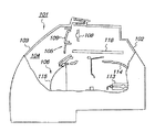
ヘッドランプやリヤコンビネーションランプ等の車両用灯具には、ハウジングとその開口部を覆うアウタレンズによって画成される灯室内の上下に上部光源ユニットと下部光源ユニットを収容して成るものがある(例えば、特許文献1参照)。斯かる車両用灯具の一例を図2に示す。 Vehicle lamps such as headlamps and rear combination lamps include an upper light source unit and a lower light source unit that are housed above and below a lamp chamber defined by an outer lens that covers a housing and its opening (for example, Patent Document 1). An example of such a vehicular lamp is shown in FIG.
図2はヘッドランプ101の要部の破断側面図であり、ハウジング102とその開口部を覆うアウタレンズ103によって画成される灯室104内の上下には上部光源ユニット105と下部光源ユニット106が収容されている。ここで、上部光源ユニット105は、光源としてLED(発光ダイオード)108を使用するものであって、その前方はインナレンズ109によって覆われている。又、下部光源ユニット106はプロジェクタ型のユニットであって、光源であるバルブ113、該バルブ113から出射する光を車両前方へと反射させるリフレクタ114、バルブ113の前方に配されたインナレンズ115等を含んで構成されている。
FIG. 2 is a cutaway side view of the main part of the
そして、灯室104内の上部光源ユニット105と下部光源ユニット106との間には遮熱板116が配されており、バルブ113によって暖められた高温の空気の上部光源ユニット105側への対流が遮熱板116によって遮断される構造が採用されている。
A
しかしながら、図2に示す従来のヘッドランプ101においては、高温の空気の上部光源ユニット105側への対流を遮熱板116によって完全に遮断することは不可能であって、長時間が経過すると上部光源ユニット105が熱的悪影響を受けるという問題があった。
However, in the
本発明は上記問題に鑑みてなされたものであり、その目的とする処は、灯室内での高温の空気の対流を遮断して光源ユニットへの熱的悪影響を防ぐことができる車両用灯具を提供することにある。 The present invention has been made in view of the above problems, and an object of the present invention is to provide a vehicular lamp that can block convection of high-temperature air in the lamp chamber and prevent a thermal adverse effect on the light source unit. It is to provide.
上記目的を達成するため、請求項1記載の発明は、ハウジングとその開口部を覆うアウタレンズによって画成される灯室内の上下に上部光源ユニットと下部光源ユニットを収容して成る車両用灯具において、前記上部光源ユニットのインナレンズによって灯室上部に密閉空間を形成し、該密閉空間内に光源を収容するとともに、前記ハウジングの上部に前記密閉空間と外部とを連通させる通気孔を形成したことを特徴とする。 In order to achieve the above-mentioned object, the invention according to claim 1 is a vehicle lamp comprising an upper light source unit and a lower light source unit which are housed above and below a lamp chamber defined by a housing and an outer lens covering the opening. A sealed space is formed in the upper part of the lamp chamber by the inner lens of the upper light source unit, a light source is accommodated in the sealed space, and a vent hole is formed in the upper part of the housing to communicate the sealed space with the outside. Features.
請求項2記載の発明は、請求項1記載の発明において、前記インナレンズの端縁を前記ハウジングの内面に形成された凹部に差し込み、その差し込み部をパッキンによって気密にシールしたことを特徴とする。 The invention according to claim 2 is characterized in that, in the invention according to claim 1, the edge of the inner lens is inserted into a recess formed in the inner surface of the housing, and the insertion part is hermetically sealed by packing. .
請求項3記載の発明は、請求項1又は2記載の発明において、前記ハウジングに形成された前記通気孔に呼吸キャップを被着したことを特徴とする。 According to a third aspect of the present invention, in the first or second aspect of the present invention, a breathing cap is attached to the vent hole formed in the housing.
請求項1記載の発明によれば、上部光源ユニットのインナレンズによって灯室上部に密閉空間を形成したため、下部光源ユニットの点灯によって暖められた高温の空気が密閉空間へと対流することがなく、長時間が経過しても密閉空間の光源が熱的悪影響を受けることがない。又、密閉空間はハウジングに形成された通気孔を介して外部と連通しているため、密閉空間内が換気され、その温度上昇が低く抑えられる。 According to the invention of claim 1, since the sealed space is formed in the upper part of the lamp chamber by the inner lens of the upper light source unit, high-temperature air warmed by lighting of the lower light source unit does not convect to the sealed space, Even if a long time elapses, the light source in the sealed space is not adversely affected by heat. Further, since the sealed space communicates with the outside through a vent hole formed in the housing, the inside of the sealed space is ventilated and the temperature rise is suppressed to a low level.
請求項2記載の発明によれば、インナレンズの端縁をハウジングの内面に形成された凹部に差し込み、その差し込み部をパッキンによって気密にシールしたため、高温の空気の密閉空間への侵入が確実に防がれる。 According to the second aspect of the present invention, the edge of the inner lens is inserted into the recess formed on the inner surface of the housing, and the insertion portion is hermetically sealed by the packing, so that high-temperature air can surely enter the sealed space. It is prevented.
請求項3記載の発明によれば、呼吸キャップの空気だけを通す機能によって密閉空間が換気されてその温度上昇が抑えられるとともに、水の侵入を防ぐ呼吸キャップの機能によって密閉空間への水の侵入が確実に防がれる。 According to the third aspect of the present invention, the sealed space is ventilated by the function of allowing only the air of the breathing cap to pass therethrough, and its temperature rise is suppressed, and the function of the breathing cap that prevents the invasion of water prevents water from entering the sealed space. Is reliably prevented.
以下に本発明の実施の形態を添付図面に基づいて説明する。 Embodiments of the present invention will be described below with reference to the accompanying drawings.
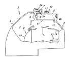
図1は本発明に係る車両用灯具の一形態としてのヘッドランプの破断側面図であり、図示のヘッドランプ1は、不図示の車両前端の左右に設けられるものであって、ハウジング2とその開口部を覆うアウタレンズ3によって画成される灯室4内の上下に上部光源ユニット5と下部光源ユニット6を収容して構成されている。
FIG. 1 is a cutaway side view of a headlamp as an embodiment of a vehicle lamp according to the present invention. The illustrated headlamp 1 is provided on the left and right of a front end of a vehicle (not shown), and includes a housing 2 and its The upper
上記ハウジング2は、樹脂にて一体成形され、その開口部の周縁には断面横U字状の嵌合凹部2aが形成されている。又、前記アウタレンズ3は、透明樹脂によって一体成形されており、その周縁に車両後方に向かって一体に突出する凸部3aはハウジング2の前記嵌合凹部2aに車両前方(図1の左方)から嵌め込まれ、その嵌め込み部がホットメルト7によって接着されることによって該アウタレンズ3がハウジング2に接合一体化されている。
The housing 2 is integrally formed of resin, and a
前記上部光源ユニット5は、光源としてLED8を使用するものであって、LED8は透明なインナレンズ9によって画成された密閉空間Sに収容されている。ここで、インナレンズ9は、その後端縁がハウジング2の上部内面に形成された凹部に差し込まれ、その差し込み部がパッキン10によって気密にシールされることによって灯室4内の上部に前記密閉空間Sが形成されている。
The upper
又、ハウジング2の上部には、密閉空間Sと外部とを連通させる通気孔11が形成されており、該通気孔11には呼吸キャップ12が被着されている。ここで、呼吸キャップ12は空気のみを通過させ、空気以外の水等の通過を阻止する機能を果たすものである。
In addition, a
他方、前記下部光源ユニット6は、プロジェクタ型のユニットであって、光源であるバルブ13、該バルブ13から出射する光を車両前方へと反射させるリフレクタ14、バルブ13の前方に配されたインナレンズ15等を含んで構成されている。
On the other hand, the lower
而して、本実施の形態に係るヘッドランプ1においては、上部光源ユニット5のインナレンズ9によって灯室4の上部に密閉空間Sを形成したため、下部光源ユニット6のバルブ13の点灯によって暖められた高温の空気が密閉空間Sへと対流することがなく、長時間が経過しても密閉空間Sに収容されたLED8が熱的悪影響を受けることがない。そして、密閉空間Sはハウジング2に形成された通気孔11を介して外部と連通しているため、密閉空間S内が換気され、その温度上昇が低く抑えられる。又、本実施の形態では、ハウジング2に形成された前記通気孔11に呼吸キャップ12を被着したため、該呼吸キャップ12の空気だけを通す機能によって密閉空間Sが換気されてその温度上昇が抑えられるとともに、水の侵入を防ぐ呼吸キャップ12の機能によって密閉空間Sへの水の侵入が確実に防がれる。
Thus, in the headlamp 1 according to the present embodiment, since the sealed space S is formed in the upper part of the
更に、本実施の形態に係るヘッドランプ1によれば、インナレンズ9の端縁をハウジング2の内面に形成された凹部2bに差し込み、その差し込み部をパッキン10によって気密にシールしたため、高温の空気の密閉空間Sへの侵入が確実に防がれるという効果が得られる。
Furthermore, according to the headlamp 1 according to the present embodiment, the end edge of the inner lens 9 is inserted into the
尚、以上は本発明をヘッドランプに対して適用した形態について説明したが、本発明は、ヘッドランプ以外の他の任意の車両用灯具に対しても同様に適用可能であることは勿論である。 In the above, the embodiment in which the present invention is applied to a headlamp has been described. However, the present invention is naturally applicable to any other vehicular lamp other than the headlamp. .
1 ヘッドランプ(車両用灯具)
2 ハウジング
2a ハウジングの嵌合凹部
2b ハウジングの凹部
3 アウタレンズ
3a アウタレンズの凸部
4 灯室
5 上部光源ユニット
6 下部光源ユニット
7 ホットメルト
8 LED(光源)
9 インナレンズ
10 パッキン
11 通気孔
12 呼吸キャップ
13 バルブ
14 リフレクタ
15 インナレンズ
S 密閉空間
1 Headlamp (vehicle lamp)
DESCRIPTION OF SYMBOLS 2
9
Claims (3)
前記上部光源ユニットのインナレンズによって灯室上部に密閉空間を形成し、該密閉空間内に光源を収容するとともに、前記ハウジングの上部に前記密閉空間と外部とを連通させる通気孔を形成したことを特徴とする車両用灯具。 In a vehicular lamp comprising an upper light source unit and a lower light source unit accommodated above and below a lamp chamber defined by an outer lens covering a housing and its opening,
A sealed space is formed in the upper part of the lamp chamber by the inner lens of the upper light source unit, a light source is accommodated in the sealed space, and a vent hole is formed in the upper part of the housing to communicate the sealed space with the outside. A vehicular lamp characterized by the above.
The vehicular lamp according to claim 1, wherein a breathing cap is attached to the vent hole formed in the housing.
Priority Applications (1)
| Application Number | Priority Date | Filing Date | Title |
|---|---|---|---|
| JP2011011611A JP2012155879A (en) | 2011-01-24 | 2011-01-24 | Vehicular lamp |
Applications Claiming Priority (1)
| Application Number | Priority Date | Filing Date | Title |
|---|---|---|---|
| JP2011011611A JP2012155879A (en) | 2011-01-24 | 2011-01-24 | Vehicular lamp |
Publications (1)
| Publication Number | Publication Date |
|---|---|
| JP2012155879A true JP2012155879A (en) | 2012-08-16 |
Family
ID=46837425
Family Applications (1)
| Application Number | Title | Priority Date | Filing Date |
|---|---|---|---|
| JP2011011611A Pending JP2012155879A (en) | 2011-01-24 | 2011-01-24 | Vehicular lamp |
Country Status (1)
| Country | Link |
|---|---|
| JP (1) | JP2012155879A (en) |
Cited By (2)
| Publication number | Priority date | Publication date | Assignee | Title |
|---|---|---|---|---|
| JP2017212100A (en) * | 2016-05-25 | 2017-11-30 | 市光工業株式会社 | Vehicular lighting fixture |
| WO2019007430A1 (en) * | 2017-07-07 | 2019-01-10 | Valeo Ichikoh (China) Auto Lighting Co. Ltd | Vehicle lamp and motor vehicle including the same |
-
2011
- 2011-01-24 JP JP2011011611A patent/JP2012155879A/en active Pending
Cited By (2)
| Publication number | Priority date | Publication date | Assignee | Title |
|---|---|---|---|---|
| JP2017212100A (en) * | 2016-05-25 | 2017-11-30 | 市光工業株式会社 | Vehicular lighting fixture |
| WO2019007430A1 (en) * | 2017-07-07 | 2019-01-10 | Valeo Ichikoh (China) Auto Lighting Co. Ltd | Vehicle lamp and motor vehicle including the same |
Similar Documents
| Publication | Publication Date | Title |
|---|---|---|
| JP5702588B2 (en) | Vehicle headlamp | |
| JP2014127381A (en) | Lamp fitting for vehicle | |
| EP2071229B1 (en) | Vehicular headlamp | |
| JP6137811B2 (en) | Vehicle lighting | |
| JP2012155879A (en) | Vehicular lamp | |
| JP4597067B2 (en) | Vehicle lamp | |
| JP2009004138A (en) | Lighting tool for vehicle | |
| JP6261303B2 (en) | Vehicle lighting | |
| JP2012155967A (en) | Lamp for vehicle | |
| JP2013025970A (en) | Vehicular lamp | |
| JP4205324B2 (en) | Vehicle lighting | |
| TWI531758B (en) | Air-cooled and moisture-resistant led lamp and bulb | |
| JP5677106B2 (en) | Vehicle lighting | |
| JP2016046105A (en) | Respiration structure of vehicle lighting appliance | |
| JP5488208B2 (en) | Vehicle lighting | |
| JP2014053143A (en) | Luminaire | |
| JP2012155962A (en) | Vehicular lamp tool | |
| JP2011165488A (en) | Lighting fixture for vehicle | |
| JP2009259453A (en) | Lighting fixture for vehicle | |
| JP2019008932A (en) | Vehicle lamp fitting and maintenance fitting | |
| TWI384163B (en) | A lamp with a heat sink | |
| JP2012155878A (en) | Vehicular lamp | |
| JPH0412565Y2 (en) | ||
| JP2007234536A (en) | Vehicle lighting fixture | |
| JP2016219194A (en) | Led bulb |