JP2012147652A - Switched reluctance motor - Google Patents
Switched reluctance motor Download PDFInfo
- Publication number
- JP2012147652A JP2012147652A JP2011208712A JP2011208712A JP2012147652A JP 2012147652 A JP2012147652 A JP 2012147652A JP 2011208712 A JP2011208712 A JP 2011208712A JP 2011208712 A JP2011208712 A JP 2011208712A JP 2012147652 A JP2012147652 A JP 2012147652A
- Authority
- JP
- Japan
- Prior art keywords
- switched reluctance
- reluctance motor
- rotor
- brush
- motor according
- Prior art date
- Legal status (The legal status is an assumption and is not a legal conclusion. Google has not performed a legal analysis and makes no representation as to the accuracy of the status listed.)
- Pending
Links
- 238000010586 diagram Methods 0.000 description 11
- 238000004804 winding Methods 0.000 description 10
- 230000005284 excitation Effects 0.000 description 7
- 239000004065 semiconductor Substances 0.000 description 3
- 238000004519 manufacturing process Methods 0.000 description 2
- 238000012986 modification Methods 0.000 description 2
- 230000004048 modification Effects 0.000 description 2
- RYGMFSIKBFXOCR-UHFFFAOYSA-N Copper Chemical compound [Cu] RYGMFSIKBFXOCR-UHFFFAOYSA-N 0.000 description 1
- XEEYBQQBJWHFJM-UHFFFAOYSA-N Iron Chemical group [Fe] XEEYBQQBJWHFJM-UHFFFAOYSA-N 0.000 description 1
- 238000007796 conventional method Methods 0.000 description 1
- 229910052802 copper Inorganic materials 0.000 description 1
- 239000010949 copper Substances 0.000 description 1
- 239000000463 material Substances 0.000 description 1
- 238000000034 method Methods 0.000 description 1
Images


Classifications
-
- A—HUMAN NECESSITIES
- A47—FURNITURE; DOMESTIC ARTICLES OR APPLIANCES; COFFEE MILLS; SPICE MILLS; SUCTION CLEANERS IN GENERAL
- A47L—DOMESTIC WASHING OR CLEANING; SUCTION CLEANERS IN GENERAL
- A47L15/00—Washing or rinsing machines for crockery or tableware
- A47L15/0076—Washing or rinsing machines for crockery or tableware of non-domestic use type, e.g. commercial dishwashers for bars, hotels, restaurants, canteens or hospitals
-
- H—ELECTRICITY
- H02—GENERATION; CONVERSION OR DISTRIBUTION OF ELECTRIC POWER
- H02K—DYNAMO-ELECTRIC MACHINES
- H02K25/00—DC interrupter motors or generators
-
- B—PERFORMING OPERATIONS; TRANSPORTING
- B08—CLEANING
- B08B—CLEANING IN GENERAL; PREVENTION OF FOULING IN GENERAL
- B08B1/00—Cleaning by methods involving the use of tools
- B08B1/10—Cleaning by methods involving the use of tools characterised by the type of cleaning tool
- B08B1/12—Brushes
-
- B—PERFORMING OPERATIONS; TRANSPORTING
- B08—CLEANING
- B08B—CLEANING IN GENERAL; PREVENTION OF FOULING IN GENERAL
- B08B1/00—Cleaning by methods involving the use of tools
- B08B1/30—Cleaning by methods involving the use of tools by movement of cleaning members over a surface
- B08B1/32—Cleaning by methods involving the use of tools by movement of cleaning members over a surface using rotary cleaning members
-
- B—PERFORMING OPERATIONS; TRANSPORTING
- B08—CLEANING
- B08B—CLEANING IN GENERAL; PREVENTION OF FOULING IN GENERAL
- B08B3/00—Cleaning by methods involving the use or presence of liquid or steam
- B08B3/02—Cleaning by the force of jets or sprays
Landscapes
- Engineering & Computer Science (AREA)
- Power Engineering (AREA)
- Synchronous Machinery (AREA)
- Control Of Electric Motors In General (AREA)
- Dc Machiner (AREA)
Abstract
Description
本発明はスイッチトリラクタンスモータに関する。 The present invention relates to a switched reluctance motor.
一般的なスイッチトリラクタンスモータ(Switched Reluctance Motor)は、固定子と回転子が全て突極(salient)である磁気構造を有する。そして、固定子に集中巻のコイルが巻かれ、回転子は如何なる励磁装置(巻線または永久磁石等)も有さずに鉄心のみで構成されるため、価格競争力に優れる。また、速度可変型スイッチトリラクタンスモータは、電力半導体を利用したコンバータと位置センサーによって連続的なトルクを安定的に発生させ、各応用分野で求められる性能に応じて容易に制御することができるという長所を有する。 A general switched reluctance motor has a magnetic structure in which a stator and a rotor are all salient. The concentrated winding coil is wound around the stator, and the rotor is composed of only an iron core without any excitation device (winding or permanent magnet), so that it is excellent in price competitiveness. In addition, the variable speed switched reluctance motor can generate a continuous torque stably by a converter using a power semiconductor and a position sensor, and can be easily controlled according to the performance required in each application field. Has advantages.
また、スイッチトリラクタンスモータは回転子の構造が簡単であり安価であるが、リラクタンストルクを発生させるためには半導体スイッチからなるコンバータを用いなければならないため、全体システムの価格が上昇するという問題点があり、高速駆動時の適切な制御のためには早い演算が可能な高価の制御回路を備えなければならないという問題点を有する。 In addition, a switched reluctance motor has a simple rotor structure and is inexpensive. However, in order to generate reluctance torque, a converter consisting of a semiconductor switch must be used, which increases the price of the entire system. There is a problem that an expensive control circuit capable of high-speed computation must be provided for appropriate control during high-speed driving.
そして、掃除機、電動工具等の分野で主に用いられるユニバーサルモータの場合、簡単な機械的構造である整流子とブラシを用いることにより、コンバータと位置センサーを用いずにトルクを発生させ、制御による性能向上よりは安価のモータ構造が長所として認められ、その分野で広く用いられている。しかし、コイルが固定子だけでなく回転子にも巻かれているため、材料費が高くなり、回転子銅損(copperloss)が発生し、モータの効率を低減させるため、高効率が求められる高級型モデルに適用することが困難であるという問題点を有する。 And in the case of universal motors mainly used in the field of vacuum cleaners, power tools, etc., by using commutators and brushes that are simple mechanical structures, torque can be generated without using converters and position sensors. As a merit, a cheaper motor structure is recognized as an advantage over the performance improvement by, and it is widely used in that field. However, since the coil is wound not only on the stator but also on the rotor, the material cost increases, rotor copper loss occurs, and the motor efficiency is reduced. There is a problem that it is difficult to apply to a mold model.
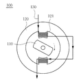
図1は従来技術によるスイッチトリラクタンスモータの概略的な構成図である。図1に一相のみが図示された前記スイッチトリラクタンスモータ100は、回転子110と、固定磁極121が形成された固定子120と、前記固定磁極121に巻かれたコイル130とを備える。そして、コイルに電流が印加されると、固定磁極に磁界が発生し、固定磁極121と回転子110との間に引力が発生して回転される。
FIG. 1 is a schematic configuration diagram of a conventional switched reluctance motor. The switched
また、複数の相巻線が複数の固定磁極に巻かれる場合、固定磁極の上巻線を一つずつ励磁させてトルクを発生させることにより、回転子を回転させる。この場合、回転子の位置フィードバックのために位置センサーが必要であり、回転子の位置に応じて固定子の巻線に電流を印加するために電力用半導体で構成されたコンバータが必要である。さらに、複雑で早い演算のために、DSP(Digital Signal Processor)またはMCU(Microcontroller Unit)などが装着された制御機が必要である。 When a plurality of phase windings are wound around a plurality of fixed magnetic poles, the rotor is rotated by exciting the upper windings of the fixed magnetic poles one by one to generate torque. In this case, a position sensor is required for the position feedback of the rotor, and a converter composed of a power semiconductor is required to apply a current to the winding of the stator according to the position of the rotor. Furthermore, a controller equipped with a DSP (Digital Signal Processor) or MCU (Microcontroller Unit) is required for complex and fast computation.
上述したように、従来技術によるスイッチトリラクタンスモータは、駆動のためにコンバータ、制御機、位置センサーが必須であるため、安価で具現することが困難であるだけでなく、複雑な技術構成により設計自由度が低下し、故障またはエラーの発生可能性が高いという問題点がある。 As described above, the switched reluctance motor according to the prior art requires a converter, a controller, and a position sensor for driving, and is not only difficult to implement at low cost but also designed with a complicated technical configuration. There is a problem that the degree of freedom is reduced and the possibility of failure or error is high.
本発明は上述のような問題点を解決するために、固定子に代えて、回転子にコイルを巻取し、一相巻線のみで連続トルクの発生が可能であるため、巻線が低減されることにより生産コストが低減されて、固定磁極の周りに空間部が形成され、余裕空間が拡大されることにより、空気の流れが増加されるため、掃除機の性能が向上するだけでなく、コンバータ及び位置センサーを備えず、整流子とブラシを用いて機械的な相転換を遂行するトルクを発生させることにより、安価で簡単な機械構造を具現することができるスイッチトリラクタンスモータを提供することを目的とする。 In order to solve the above-described problems, the present invention can reduce the number of windings by winding a coil around a rotor instead of a stator and generating a continuous torque with only a single-phase winding. As a result, the production cost is reduced, a space is formed around the fixed magnetic pole, and the marginal space is expanded, so that the air flow is increased, which not only improves the performance of the vacuum cleaner. Provided is a switched reluctance motor which can be realized at low cost and with a simple mechanical structure by generating torque for performing mechanical phase change using a commutator and a brush, without a converter and a position sensor. For the purpose.
また、本発明は、モータの性能に直接影響を与える進み角(Advance Angle)と導通角(Dwell Angle)を、整流子とブラシの位置及びアーク角(Arc Angle)を変更して調整することにより、最適運転点(最大効率、最大トルク)に応じた設計が可能であるだけでなく、その設計技法を利用して二対の固定磁極から発生する夫々の正トルク領域を調整して重畳トルクを可変することができるため、トルクリプルの低減設計が可能であるスイッチトリラクタンスモータを提供することを目的とする。 Further, the present invention adjusts the advance angle and advance angle (Dwell Angle) that directly affect the performance of the motor by changing the position of the commutator and the brush and the arc angle (Arc Angle). In addition to being able to design in accordance with the optimum operating point (maximum efficiency, maximum torque), the design torque can be used to adjust the respective positive torque regions generated from the two pairs of fixed magnetic poles, thereby superimposing torque. An object of the present invention is to provide a switched reluctance motor that can be designed to reduce torque ripple.
上述した本発明の目的を果たすために、本発明によるスイッチトリラクタンスモータは、コイルが巻線された回転子と、前記回転子の両端部に連結された整流子と、前記回転子の回転によって整流子と機械的に接触されるブラシと、前記ブラシが固定され、固定磁極を有する固定子と、を含み、前記ブラシは固定磁極の連結軸から進み角だけ移動されて装着される。 In order to achieve the above-described object of the present invention, a switched reluctance motor according to the present invention includes a rotor around which a coil is wound, a commutator connected to both ends of the rotor, and rotation of the rotor. A brush that is in mechanical contact with a commutator; and a stator having the fixed magnetic pole and having a fixed magnetic pole, the brush being moved from the connecting shaft of the fixed magnetic pole by a leading angle and mounted.
また、前記回転子が時計回り方向に回転される場合、前記ブラシは互いに対向する固定磁極の連結軸から反時計回り方向に進み角だけ移動されて装着され、前記進み角は電圧印加後のインダクタンス上昇前までの領域である。 Further, when the rotor is rotated in the clockwise direction, the brush is mounted while being moved by an advance angle in a counterclockwise direction from the connecting shafts of the fixed magnetic poles facing each other, and the advance angle is an inductance after voltage application. This is the area before the rise.
また、前記整流子とブラシのアーク角によって電圧印加区間である導通角が調整される。 Further, the conduction angle, which is a voltage application section, is adjusted by the arc angle of the commutator and the brush.
また、前記導通角はd=X+2Yに定義され、ここで、Xはブラシのアーク角、Yは整流子のアーク角である。 The conduction angle is defined as d = X + 2Y, where X is the arc angle of the brush and Y is the arc angle of the commutator.
また、前記導通角は負トルク発生前に電圧がオフされるように設定される。 The conduction angle is set so that the voltage is turned off before the negative torque is generated.
また、前記整流子の両端に回転子に巻線されたコイルが連結される。 In addition, a coil wound around a rotor is connected to both ends of the commutator.
また、前記ブラシは互いに対向する二対が備えられ、一対のブラシ端部には電源が連結され、他の一対のブラシにはダイオードが連結される。 The brush is provided with two pairs facing each other, a power source is connected to a pair of brush ends, and a diode is connected to the other pair of brushes.
また、前記固定磁極は永久磁石であることができる。 The fixed magnetic pole may be a permanent magnet.
また、前記固定子と回転子は突極型である。 The stator and rotor are salient pole types.
本発明の特徴及び利点は添付図面に基づいた以下の詳細な説明によってさらに明らかになるであろう。 The features and advantages of the present invention will become more apparent from the following detailed description taken in conjunction with the accompanying drawings.
本発明の詳細な説明に先立ち、本明細書及び請求範囲に用いられた用語や単語は通常的かつ辞書的な意味に解釈されてはならず、発明者が自らの発明を最善の方法で説明するために用語の概念を適切に定義することができるという原則にしたがって本発明の技術的思想にかなう意味と概念に解釈されるべきである。 Prior to the detailed description of the invention, the terms and words used in the specification and claims should not be construed in a normal and lexicographic sense, and the inventor best describes the invention. Therefore, it should be construed as meanings and concepts corresponding to the technical idea of the present invention in accordance with the principle that the concept of terms can be appropriately defined.
本発明は、固定子に代えて、回転子にコイルを巻取し、一相巻線のみで連続トルクの発生が可能であるため、巻線が低減されることにより生産コストが低減される。また、固定磁極の周りに空間部が形成され、余裕空間が拡大されることにより、空気の流れが増加されるため、掃除機の性能が向上するだけでなく、コンバータ及び位置センサーを備えず、整流子とブラシを用いて機械的な相転換を遂行するトルクを発生させることにより、安価で簡単な機械構造を具現することができる。また、モータの性能に直接影響を与える進み角(Advance Angle)と導通角(Dwell Angle)を、整流子とブラシの位置及びアーク角(Arc Angle)を変更して調整することにより、最適運転点(最大効率、最大トルク)に応じた設計が可能であるだけでなく、その設計技法を利用して二対の固定磁極から発生する夫々の正トルク領域を調整して重畳トルクを可変することができるため、トルクリプルの低減設計が可能であるスイッチトリラクタンスモータを提供する効果を有する。 In the present invention, a coil is wound around a rotor instead of a stator, and continuous torque can be generated only by a single-phase winding. Therefore, the production cost is reduced by reducing the number of windings. In addition, since a space is formed around the fixed magnetic pole and the marginal space is expanded, the flow of air is increased, so not only the performance of the vacuum cleaner is improved, but the converter and the position sensor are not provided, By generating a torque for performing mechanical phase change using a commutator and a brush, an inexpensive and simple mechanical structure can be realized. In addition, by adjusting the advance angle (Advanced Angle) and conduction angle (Dwell Angle) that directly affect the performance of the motor by changing the position of the commutator and the brush and the arc angle (Arc Angle), the optimum operating point In addition to being able to design according to (maximum efficiency, maximum torque), it is possible to vary the superimposed torque by adjusting the respective positive torque regions generated from two pairs of fixed magnetic poles using the design technique. Therefore, it is possible to provide a switched reluctance motor that can be designed to reduce torque ripple.
本発明の目的、特定の長所及び新規の特徴は添付図面に係る以下の詳細な説明および好ましい実施例によってさらに明らかになるであろう。本明細書において、各図面の構成要素に参照番号を付け加えるに際し、同一の構成要素に限っては、たとえ異なる図面に示されてもできるだけ同一の番号を付けるようにしていることに留意しなければならない。また、本発明の説明において、係わる公知技術に対する具体的な説明が本発明の要旨を不明瞭にする可能性があると判断される場合は、その詳細な説明を省略する。 Objects, specific advantages and novel features of the present invention will become more apparent from the following detailed description and preferred embodiments with reference to the accompanying drawings. In this specification, when adding reference numerals to the components of each drawing, it should be noted that the same components are given the same numbers as much as possible even if they are shown in different drawings. Don't be. Further, in the description of the present invention, if it is determined that a specific description of the related art may obscure the gist of the present invention, a detailed description thereof will be omitted.
以下、添付された図面を参照して本発明の好ましい実施例によるスイッチトリラクタンスモータについて詳細に説明する。 Hereinafter, a switched reluctance motor according to a preferred embodiment of the present invention will be described in detail with reference to the accompanying drawings.
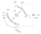
図2は本発明によるスイッチトリラクタンスモータの概略的な構成図である。図示したように、前記スイッチトリラクタンスモータ200は、回転子210と、整流子220a、220bと、ブラシ230a、230b、230c、230dと、コイル240と、固定子250と、を含む。
FIG. 2 is a schematic configuration diagram of a switched reluctance motor according to the present invention. As illustrated, the switched
より具体的には、前記回転子210にコイルが巻線されており、前記回転子の両端部には整流子220a、220bが連結され、前記整流子220a、220bには回転子210に巻線されたコイル240が連結される。この際、前記回転子の中心軸が二つの整流子220a、220bの中心軸と一致するように連結される。また、前記固定子250と回転子210は突極型である。
More specifically, a coil is wound around the
また、前記ブラシ230a、230b、230c、230dは互いに対向する二対が備えられ、固定子250に固定される。前記固定子250は互いに対向する二対の固定磁極251を備え、前記ブラシは前記回転子210の回転によって整流子220と機械的に接触される。そして、前記回転子が時計回り方向に回転される場合、前記ブラシは互いに対向する固定磁極251の連結軸から反時計回り方向に進み角aだけ移動されて装着される。
The
そして、一対のブラシ230a、230bには電源(不図示)が連結され、他の一対のブラシ230c、230dにはダイオード260が連結される。
A power source (not shown) is connected to the pair of
本発明による前記固定磁極251はトルク強化のために永久磁石からなることができる。
The fixed
このように構成されることにより、回転子210の回転によって同軸の整流子220a、220bがともに回転し、ブラシと機械的に接触されることにより電圧がオン/オフされる。
With this configuration, the
以下、上述のように構成された本発明によるスイッチトリラクタンスモータの構造及び作動原理についてより詳細に説明する。 Hereinafter, the structure and operating principle of the switched reluctance motor according to the present invention configured as described above will be described in more detail.
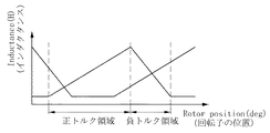
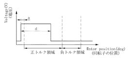
図3は本発明によるスイッチトリラクタンスモータにおいて、回転子の位置によるインダクタンスを図示したグラフであり、図4は本発明によるスイッチトリラクタンスモータにおいて、回転子の位置による電圧印加を図示したグラフであり、図5は本発明によるスイッチトリラクタンスモータにおいて、整流子とブラシの位置による進み角及び導通角の設定を示した使用状態図である。 FIG. 3 is a graph illustrating inductance depending on the rotor position in the switched reluctance motor according to the present invention. FIG. 4 is a graph illustrating voltage application depending on the rotor position in the switched reluctance motor according to the present invention. FIG. 5 is a use state diagram showing the setting of the lead angle and the conduction angle depending on the positions of the commutator and the brush in the switched reluctance motor according to the present invention.
図示したように、インダクタンスの特性上、電圧の印加時に所望の電流値に直ちに到逹せず、電圧のオフ時に電流が直ちに消滅されない。従って、最小インダクタンス区間で電流形成(build−up)のための進み角aと負トルク発生前に電圧をオフさせる導通角の設計が重要である。これにより、従来技術による位置センサー及びコンバータの役割を具現することができるようになる。 As shown in the figure, due to the characteristics of inductance, a desired current value is not reached immediately when a voltage is applied, and the current is not immediately extinguished when the voltage is turned off. Therefore, it is important to design a lead angle a for build-up in the minimum inductance section and a conduction angle for turning off the voltage before the negative torque is generated. Accordingly, the roles of the position sensor and the converter according to the conventional technique can be realized.
より具体的には、

(T:トルク、θ:回転子の位置、i:相電流、L:インダクタンス)
前記式から分かるように、発生された電流とインダクタンスの変化率によってトルクが決められる。
More specifically,
(T: torque, θ: rotor position, i: phase current, L: inductance)
As can be seen from the above equation, the torque is determined by the rate of change of the generated current and the inductance.
従って、前記進み角は電圧印加後のインダクタンス上昇前までの領域であり、進み角aだけ電圧が印加され、その後、インダクタンスが上昇して正トルク領域が形成されて、導通角dである電圧印加区間は前記ブラシのアーク角Xと整流子のアーク角Yによって調整される。結局、導通角はd=X+2Yに定義され、ここで、Xはブラシのアーク角、Yは整流子のアーク角である。 Therefore, the advance angle is a region before the inductance rises after the voltage application, and the voltage is applied by the advance angle a, and then the inductance rises to form a positive torque region, and the voltage application that is the conduction angle d is applied. The interval is adjusted by the arc angle X of the brush and the arc angle Y of the commutator. Eventually, the conduction angle is defined as d = X + 2Y, where X is the arc angle of the brush and Y is the arc angle of the commutator.
そして、前記導通角dは負トルク発生前に電圧がオフされるように設定される。 The conduction angle d is set so that the voltage is turned off before the negative torque is generated.
以下、本発明によるスイッチトリラクタンスモータのトルク発生及び相転換について詳細に説明する。 Hereinafter, torque generation and phase change of the switched reluctance motor according to the present invention will be described in detail.
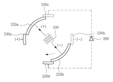
図6及び図7は本発明によるスイッチトリラクタンスモータにおいて、コイル励磁による概略的な使用状態図であり、図8は本発明によるスイッチトリラクタンスモータにおいて、相転換される概略的な使用状態図である。図示したように、ブラシ230aに(+)電圧が印加され、ブラシ230bに(−)電圧が印加されて、前記コイル240に電流が流れると、整流子220a、220bはブラシ230a、230bと接触された状態で時計回り方向に回転される。
FIG. 6 and FIG. 7 are schematic use state diagrams by coil excitation in the switched reluctance motor according to the present invention, and FIG. 8 is a schematic use state diagram that is phase-shifted in the switched reluctance motor according to the present invention. is there. As illustrated, when a (+) voltage is applied to the
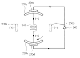
そして、図7に図示したように、前記整流子220a、220bは、上/下、左/右のブラシ230a、230b、230c、230dに全て接するようになる。この際、ダイオード260に逆電圧が印加されて導通されない。
As shown in FIG. 7, the
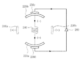
そして、図8に図示したように、前記整流子220a、220bが上/下のブロシ230c、230dにのみ接する場合、左/右のブラシ230a、230bによる外部電圧の印加が発生せず、コイルのインダクタンス性質によって電圧が反転される。また、コイルに同じ方向電流が流れ、ダイオードに定電圧が印加される。
As shown in FIG. 8, when the
図9及び図10は本発明によるスイッチトリラクタンスモータにおいて、コイル励磁による概略的な使用状態図であり、図11は本発明によるスイッチトリラクタンスモータにおいて、相転換される概略的な使用状態図である。図示したように、ブラシ230bに(+)電圧が印加され、ブラシ230aに(−)電圧が印加されて、前記コイル240に電流が流れると、整流子220a、220bはブラシ230a、230bと接触された状態で時計回り方向に回転される。
FIG. 9 and FIG. 10 are schematic use state diagrams by coil excitation in the switched reluctance motor according to the present invention, and FIG. 11 is a schematic use state diagram that is phase-shifted in the switched reluctance motor according to the present invention. is there. As illustrated, when a (+) voltage is applied to the
また、図10に図示したように、前記整流子220a、220bは、上/下、左/右のブラシ230a、230b、230c、230dに全て接するようになる。この際、ダイオード260に逆電圧が印加されて導通されない。
Also, as shown in FIG. 10, the
また、図11に図示したように、前記整流子220a、220bが上/下のブロシ230c、230dにのみ接する場合、左/右のブラシ230a、230bによる外部電圧の印加が発生せず、コイルのインダクタンス性質によって電圧が反転される。また、コイルに同じ方向の電流が流れ、ダイオードに定電圧が印加される。
Further, as shown in FIG. 11, when the
以上、本発明を具体的な実施例に基づいて詳細に説明したが、これは本発明を具体的に説明するためのものであり、本発明によるスイッチトリラクタンスモータはこれに限定されず、該当分野における通常の知識を有する者であれば、本発明の技術的思想内にての変形や改良が可能であることは明白であろう。 As described above, the present invention has been described in detail based on the specific embodiments. However, this is intended to specifically describe the present invention, and the switched reluctance motor according to the present invention is not limited to this. It will be apparent to those skilled in the art that modifications and improvements can be made within the technical idea of the present invention.
本発明の単純な変形乃至変更はいずれも本発明の領域に属するものであり、本発明の具体的な保護範囲は添付の特許請求の範囲により明確になるであろう。 All simple variations and modifications of the present invention belong to the scope of the present invention, and the specific scope of protection of the present invention will be apparent from the appended claims.
100 スイッチトリラクタンスモータ
110 回転子
120 固定子
121 固定磁極
130 コイル
200 スイッチトリラクタンスモータ
210 回転子
220a、220b 整流子
230a、230b、230c、230d ブラシ
240 コイル
250 固定子
251 固定磁極
DESCRIPTION OF
Claims (9)
前記回転子の両端部に連結された整流子と、
前記回転子の回転によって整流子と機械的に接触されるブラシと、
前記ブラシが固定され、固定磁極を有する固定子と、を含み、
前記ブラシは互いに対向する固定磁極の連結軸から進み角だけ移動されて装着されることを特徴とするスイッチトリラクタンスモータ。 A rotor around which a coil is wound;
A commutator coupled to both ends of the rotor;
A brush that is in mechanical contact with the commutator by rotation of the rotor;
A stator to which the brush is fixed and having a fixed magnetic pole,
The switched reluctance motor according to claim 1, wherein the brush is mounted while being moved by a lead angle from a connecting shaft of fixed magnetic poles facing each other.
ここで、Xはブラシのアーク角、Yは整流子のアーク角であることを特徴とする請求項3に記載のスイッチトリラクタンスモータ。 The conduction angle is defined as d = X + 2Y,
4. The switched reluctance motor according to claim 3, wherein X is an arc angle of the brush, and Y is an arc angle of the commutator.
Applications Claiming Priority (2)
| Application Number | Priority Date | Filing Date | Title |
|---|---|---|---|
| KR10-2011-0002436 | 2011-01-10 | ||
| KR1020110002436A KR20120080951A (en) | 2011-01-10 | 2011-01-10 | Mechanically commutated switched reluctance motor |
Publications (1)
| Publication Number | Publication Date |
|---|---|
| JP2012147652A true JP2012147652A (en) | 2012-08-02 |
Family
ID=46454725
Family Applications (1)
| Application Number | Title | Priority Date | Filing Date |
|---|---|---|---|
| JP2011208712A Pending JP2012147652A (en) | 2011-01-10 | 2011-09-26 | Switched reluctance motor |
Country Status (5)
| Country | Link |
|---|---|
| US (1) | US20120175997A1 (en) |
| JP (1) | JP2012147652A (en) |
| KR (1) | KR20120080951A (en) |
| CN (1) | CN102594074A (en) |
| DE (1) | DE102011116382A1 (en) |
Cited By (1)
| Publication number | Priority date | Publication date | Assignee | Title |
|---|---|---|---|---|
| JP2022166135A (en) * | 2015-11-05 | 2022-11-01 | ザ・ボーイング・カンパニー | eddy current repulsion motor |
Families Citing this family (7)
| Publication number | Priority date | Publication date | Assignee | Title |
|---|---|---|---|---|
| KR101184461B1 (en) * | 2011-01-10 | 2012-09-19 | 삼성전기주식회사 | Mechanically Commutated Switched reluctance motor |
| CN103466758B (en) * | 2013-09-24 | 2015-07-15 | 杨作红 | Composite cathode and electrochemical multiple-stage water treatment equipment utilizing same |
| US9634585B2 (en) | 2014-02-20 | 2017-04-25 | General Electric Company | Control method for reducing torque ripple in an electrical machine |
| US9246429B2 (en) | 2014-02-20 | 2016-01-26 | General Electric Company | Control method for reducing torque ripple in switched reluctance motors |
| CN103840611A (en) * | 2014-03-27 | 2014-06-04 | 重庆万力联兴实业(集团)有限公司 | Method for prolong service life of permanent magnet direct current motor of automobile fuel pump |
| KR101675229B1 (en) * | 2015-07-07 | 2016-11-22 | (주)타마스 | Dc motor for vehicle |
| CN109261572A (en) * | 2018-09-26 | 2019-01-25 | 江苏理工学院 | A kind of automation finish machining equipment of step motor stator |
Citations (9)
| Publication number | Priority date | Publication date | Assignee | Title |
|---|---|---|---|---|
| US4567407A (en) * | 1982-06-25 | 1986-01-28 | Ecklin John W | Biased unitized motor alternator with stationary armature and field |
| JPS6176051A (en) * | 1984-09-19 | 1986-04-18 | Secoh Giken Inc | Commutator motor of reluctance type |
| JPH04222493A (en) * | 1990-03-07 | 1992-08-12 | Branislav Tepavcevic | Motor driver and electric driver |
| US5168203A (en) * | 1990-03-07 | 1992-12-01 | Branislav Tepavcevic | Constant current reluctance motor drive systems |
| JP2001186737A (en) * | 1999-12-27 | 2001-07-06 | Shinano Kenshi Co Ltd | Motor |
| WO2001050578A1 (en) * | 2000-01-03 | 2001-07-12 | Tridelta Industries, Inc. | Mechanically commutated switched reluctance motor |
| JP2007166876A (en) * | 2005-12-16 | 2007-06-28 | Denso Corp | Meandering field coil type rotary electric machine |
| US20070152532A1 (en) * | 2003-12-30 | 2007-07-05 | Gerald Roos | Electrical machine with commutator rotor |
| WO2010083776A1 (en) * | 2009-01-24 | 2010-07-29 | Feng Lumin | Dc commutator doubly salient reluctance motor |
Family Cites Families (8)
| Publication number | Priority date | Publication date | Assignee | Title |
|---|---|---|---|---|
| GB2234863B (en) * | 1989-08-09 | 1993-04-14 | Harold Aspden | Switched reluctance motor with full cycle a.c. commutation |
| CN2288546Y (en) * | 1996-09-09 | 1998-08-19 | 孙学政 | Mechanical reluctance communator electric machine |
| JP2000228854A (en) * | 1999-02-08 | 2000-08-15 | Mitsubishi Electric Corp | Reluctance motor and blower |
| RU2303536C2 (en) * | 2003-04-18 | 2007-07-27 | Ултра Мотор Компани Лимитед | Electric motor |
| CN101267149A (en) * | 2008-04-25 | 2008-09-17 | 浙江强裕经贸有限公司 | Direct current motor |
| KR101016015B1 (en) * | 2009-03-04 | 2011-02-23 | 김진선 | switched reluctance motor |
| US9246093B2 (en) | 2009-07-01 | 2016-01-26 | Micron Technology, Inc. | Phase change memory cell with self-aligned vertical heater and low resistivity interface |
| KR101184461B1 (en) * | 2011-01-10 | 2012-09-19 | 삼성전기주식회사 | Mechanically Commutated Switched reluctance motor |
-
2011
- 2011-01-10 KR KR1020110002436A patent/KR20120080951A/en not_active Application Discontinuation
- 2011-09-26 JP JP2011208712A patent/JP2012147652A/en active Pending
- 2011-09-30 US US13/249,597 patent/US20120175997A1/en not_active Abandoned
- 2011-10-12 DE DE102011116382A patent/DE102011116382A1/en not_active Withdrawn
- 2011-10-13 CN CN2011103099496A patent/CN102594074A/en active Pending
Patent Citations (9)
| Publication number | Priority date | Publication date | Assignee | Title |
|---|---|---|---|---|
| US4567407A (en) * | 1982-06-25 | 1986-01-28 | Ecklin John W | Biased unitized motor alternator with stationary armature and field |
| JPS6176051A (en) * | 1984-09-19 | 1986-04-18 | Secoh Giken Inc | Commutator motor of reluctance type |
| JPH04222493A (en) * | 1990-03-07 | 1992-08-12 | Branislav Tepavcevic | Motor driver and electric driver |
| US5168203A (en) * | 1990-03-07 | 1992-12-01 | Branislav Tepavcevic | Constant current reluctance motor drive systems |
| JP2001186737A (en) * | 1999-12-27 | 2001-07-06 | Shinano Kenshi Co Ltd | Motor |
| WO2001050578A1 (en) * | 2000-01-03 | 2001-07-12 | Tridelta Industries, Inc. | Mechanically commutated switched reluctance motor |
| US20070152532A1 (en) * | 2003-12-30 | 2007-07-05 | Gerald Roos | Electrical machine with commutator rotor |
| JP2007166876A (en) * | 2005-12-16 | 2007-06-28 | Denso Corp | Meandering field coil type rotary electric machine |
| WO2010083776A1 (en) * | 2009-01-24 | 2010-07-29 | Feng Lumin | Dc commutator doubly salient reluctance motor |
Cited By (2)
| Publication number | Priority date | Publication date | Assignee | Title |
|---|---|---|---|---|
| JP2022166135A (en) * | 2015-11-05 | 2022-11-01 | ザ・ボーイング・カンパニー | eddy current repulsion motor |
| JP7472207B2 (en) | 2015-11-05 | 2024-04-22 | ザ・ボーイング・カンパニー | Eddy Current Repulsion Motor |
Also Published As
| Publication number | Publication date |
|---|---|
| US20120175997A1 (en) | 2012-07-12 |
| DE102011116382A1 (en) | 2012-07-12 |
| CN102594074A (en) | 2012-07-18 |
| KR20120080951A (en) | 2012-07-18 |
Similar Documents
| Publication | Publication Date | Title |
|---|---|---|
| JP2012147652A (en) | Switched reluctance motor | |
| JP5730736B2 (en) | Permanent magnet type rotating electric machine and vehicle equipped with permanent magnet type rotating electric machine | |
| JP5513608B2 (en) | Claw pole type AC electric motor | |
| CN105449881B (en) | Low six phase doubly-salient brushless DC generator of mutual inductance error-tolerance type | |
| JP2012147653A (en) | Switched reluctance motor | |
| WO2017038311A1 (en) | Rotor for rotary electric machine, rotary electric machine, and vehicle | |
| EP2290790A3 (en) | Permanent magnet brushless machine with magnetic flux regulation | |
| JP2010115086A (en) | Motor system and energization method of permanent magnet motor | |
| JP2014192951A (en) | Dynamo-electric machine, electric motor unit and generator unit | |
| JP2001169517A (en) | Capacitor motor | |
| JP2013042574A (en) | Permanent magnet type rotating electrical machine | |
| JP2009153358A (en) | Flat motor | |
| CN112165231B (en) | Complementary axial air gap flux permanent magnet switch reluctance motor | |
| JP2009142130A (en) | Rotating electric machine and drive device for rotating electric machine | |
| JP5460807B1 (en) | Synchronous motor | |
| US10749397B2 (en) | Brushless DC dynamo | |
| JP2001238417A (en) | Electrical machine | |
| JP6613721B2 (en) | Toroidal coil motor | |
| JP6504850B2 (en) | Control device, rotary electric machine using the same, and drive system including the control device and the rotary electric machine | |
| JP4199218B2 (en) | Electric motor | |
| JP2016041004A (en) | Motor for switching current of stator's electromagnets by fixed commutator using permanent magnets and brushes for rotors and using electromagnets for stators, in direct current motor (dc motor) | |
| JP2016158401A (en) | Rotor for rotary electric machine, and rotary electric machine with the same | |
| JP2022129703A (en) | Rotary electric machine, and electric blower and electric cleaner using the same | |
| TWM501044U (en) | Brushless DC motor | |
| US8896180B2 (en) | Switched reluctance motor having a vertical moving commutator |
Legal Events
| Date | Code | Title | Description |
|---|---|---|---|
| A621 | Written request for application examination |
Free format text: JAPANESE INTERMEDIATE CODE: A621 Effective date: 20140926 |
|
| A977 | Report on retrieval |
Free format text: JAPANESE INTERMEDIATE CODE: A971007 Effective date: 20150831 |
|
| A131 | Notification of reasons for refusal |
Free format text: JAPANESE INTERMEDIATE CODE: A131 Effective date: 20150915 |
|
| A02 | Decision of refusal |
Free format text: JAPANESE INTERMEDIATE CODE: A02 Effective date: 20160301 |