JP2012144343A - Lift fork of reach type traveling lifter - Google Patents

Lift fork of reach type traveling lifter Download PDF

Info

Publication number
JP2012144343A
JP2012144343A JP2011004448A JP2011004448A JP2012144343A JP 2012144343 A JP2012144343 A JP 2012144343A JP 2011004448 A JP2011004448 A JP 2011004448A JP 2011004448 A JP2011004448 A JP 2011004448A JP 2012144343 A JP2012144343 A JP 2012144343A
Authority
JP
Japan
Prior art keywords
lift
cross
fork
link
guide rolls
Prior art date
Legal status (The legal status is an assumption and is not a legal conclusion. Google has not performed a legal analysis and makes no representation as to the accuracy of the status listed.)
Pending
Application number
JP2011004448A
Other languages
Japanese (ja)
Inventor
Norihiro Ide
宣弘 井手
Current Assignee (The listed assignees may be inaccurate. Google has not performed a legal analysis and makes no representation or warranty as to the accuracy of the list.)
Atex Co Ltd
Original Assignee
Atex Co Ltd
Priority date (The priority date is an assumption and is not a legal conclusion. Google has not performed a legal analysis and makes no representation as to the accuracy of the date listed.)
Filing date
Publication date
Application filed by Atex Co Ltd filed Critical Atex Co Ltd
Priority to JP2011004448A priority Critical patent/JP2012144343A/en
Publication of JP2012144343A publication Critical patent/JP2012144343A/en
Pending legal-status Critical Current

Links

Images

Landscapes

  • Forklifts And Lifting Vehicles (AREA)

Abstract

PROBLEM TO BE SOLVED: To simplify the operation structure and scooping operation of a lift fork by controlling the scooping action and scooping angle of the lift fork by extending and contracting a cross-link mechanism without installing a special expansion cylinder for controlling the scooping angle of the lift fork.SOLUTION: A lifting body S including a fork 5 for scooping a load provided at the front is made longitudinally movable by the cross-link mechanism K, and a longitudinal gap BB between both fulcrum shafts 14, 24 is set shorter than a longitudinal gap AA between both rotating shafts 26, 16 of the cross-link mechanism K.

Description

この発明は、アウトリガーを有した形態のリーチ型走行リフターにおいて、荷物の掬取効果を簡単な構成によって良好に維持させるリフトフォークに関する。   The present invention relates to a lift fork that can satisfactorily maintain a towing effect of a load with a simple structure in a reach type travel lifter having an outrigger.

アウトリガーを配したリーチ型の走行リフターにおいて、荷物の掬取効果をよくするために、荷物掬取時にフォークの先端部を前下り傾斜にしたり、前上り傾斜にするようにチルトシリンダを設けて作動させる技術(例えば、特許文献1参照)が知られている。   In reach type lifters with outriggers, a tilt cylinder is installed to tilt the front end of the fork forward or tilt forward when picking up the luggage to improve the luggage collection effect. The technique (for example, refer patent document 1) to make is known.

特開平8−91797号公報JP-A-8-91797

リフトフォークの掬取角度を制御するために制御シリンダを装着する形態は、特別の伸縮シリンダ、及びこのシリンダを伸縮制御するための油圧回路や、操作機構等を要して、構成、及び操作が煩雑になり、重量も増加し、生産費も高くなる。この発明は、このようなリフトフォークの掬取角度を制御する特別の伸縮シリンダを設けることなく、クロスリンク機構を拡縮することによって、リフトフォークの掬取作用と、掬取角度を制御させて、リフトフォークの作動構成、及び掬取操作を簡単、容易にするものである。   The configuration in which the control cylinder is mounted to control the lifting angle of the lift fork requires a special telescopic cylinder, a hydraulic circuit for controlling the expansion and contraction of the cylinder, an operation mechanism, and the like. It becomes complicated, the weight increases, and the production cost increases. The present invention controls the lifting fork and the take-off angle by expanding and reducing the cross-link mechanism without providing a special telescopic cylinder for controlling the take-up angle of the lift fork, It is intended to simplify and facilitate the lift fork operating configuration and towing operation.

請求項1に記載の発明は、機台9の下方左右両端部から前方へ突出するアウトリガー12と、機台9から立設するリフト支柱Rに沿って昇降自在の昇降体Sを備え、該昇降体S前側には前方へ向け突出するフォーク5を取着し、前記アウトリガー12前端部と機台9下方の車輪10,11で走行することのできるリーチ型走行リフターのリフトフォークであって、該昇降体Sを、リフト支柱R側のリフトブラケット7とフォーク5側のフロントリンク4と、このリフトブラケット7及びフロントリンク4間を伸縮可能なクロスリンク機構Kとで構成し、該クロスリンク機構Kのクロスリンク1,2下端部をリフトブラケット7とフロントリンク4との各々の下端部支点軸14,24へ枢支し、クロスリンク1,2上端部にはガイドロール27,28を設け、両クロスリンク1,2をクロスピボット3周りに回動させた際、ガイドロール27,28がリフトブラケット7とフロントリンク4の縦方向の案内体15,25に沿って摺動案内されるよう構成するとともに、両ガイドロール27,28の回動軸26,16の前後方向間隔AAよりも両支点軸14,24の前後方向間隔BBを短く設定し、更に、クロスリンク1,2の回動軸16と支点軸14との間をリフト支柱Rと略平行に配置した単一のシリンダ6で連結してなるリーチ型走行リフターのリフトフォークの構成とする。   The invention described in claim 1 includes an outrigger 12 projecting forward from the lower left and right ends of the machine base 9 and a lift S that can be raised and lowered along a lift column R standing from the machine base 9. A fork 5 that protrudes forward is attached to the front side of the body S, and is a lift fork of a reach type travel lifter that can travel on the front end portion of the outrigger 12 and the wheels 10 and 11 below the machine base 9, The lifting body S includes a lift bracket 7 on the lift column R side, a front link 4 on the fork 5 side, and a cross link mechanism K that can extend and contract between the lift bracket 7 and the front link 4. The lower ends of the cross links 1, 2 are pivotally supported on the lower end fulcrum shafts 14, 24 of the lift bracket 7 and the front link 4, and the guide rolls 27 are provided at the upper ends of the cross links 1, 2. 28, when both cross links 1 and 2 are rotated around the cross pivot 3, the guide rolls 27 and 28 slide along the longitudinal guide bodies 15 and 25 of the lift bracket 7 and the front link 4. In addition, the longitudinal distance BB of the fulcrum shafts 14, 24 is set to be shorter than the longitudinal distance AA of the pivot shafts 26, 16 of both guide rolls 27, 28. The lift fork of the reach type travel lifter is formed by connecting the rotating shaft 16 and the fulcrum shaft 14 with a single cylinder 6 disposed substantially parallel to the lift column R.

又、下部アーム1Aと下部アーム2Bとを同長さとし、上部アーム1Aと上部アーム1Bとを同長さに設定してなるリーチ型走行リフターのリフトフォークとする。   Further, a lift fork of a reach type travel lifter in which the lower arm 1A and the lower arm 2B have the same length and the upper arm 1A and the upper arm 1B have the same length is used.

請求項1に記載の発明は、昇降体Sを、リフト支柱R側のリフトブラケット7とフォーク5側のフロントリンク4と、このリフトブラケット7及びフロントリンク4間を伸縮可能なクロスリンク機構Kとで構成し、該クロスリンク機構Kのクロスリンク1,2下端部をリフトブラケット7とフロントリンク4との各々の下端部支点軸14,24へ枢支し、クロスリンク1,2上端部にはガイドロール27,28を設け、両クロスリンク1,2をクロスピボット3周りに回動させた際、ガイドロール27,28がリフトブラケット7とフロントリンク4の縦方向の案内体15,25に沿って摺動案内されるよう構成するとともに、クロスリンク1,2の回動軸16と支点軸14との間を側面視においてリフト支柱Rと略平行に配置した単一のシリンダ6で連結して伸縮するようにしてあるので、シリンダ6を伸縮させ、クロスリンク機構Kを作動させる際のシリンダ6の傾動がなく油圧ホースや電線等の配索が容易であり、クロスリンク機構の前後長さを小さくコンパクトに構成することができる。又、両ガイドロール27,28の回動軸26,16の前後方向間隔AAよりも両支点軸14,24の前後方向間隔BBを短く設定してあるので、フォーク5を前方へ移動させる時には、フォーク5が下降しながら前方へ移動し荷物の下面にフォーク5先端を挿入し易く、この状態でフォーク5を上昇させて荷物を掬取後、クロスリンク機構Kを縮めてフォーク5をリフト支柱R側へ向け引き込む時に、フォーク5上面の角度はその先端部が上方へ移動しながら、荷物が前側へすべり落ちないよう後方下り傾斜に、自動的に傾動し、フォーク5の前、後移動とともに掬取角度の変移が行われるものであるから、構成が単純で簡単であり、軽量、安価にできる。更に、クロスリンク機構Kの支点軸14,24を下側にしていることで、クロスリンク機構Kを伸ばした際に両クロスリンク1,2が下方へ移動するので重心が下がることとなり、掬取動作が安定するという効果もある。   According to the first aspect of the present invention, the lifting body S includes a lift bracket 7 on the lift column R side and a front link 4 on the fork 5 side, and a cross link mechanism K that can extend and contract between the lift bracket 7 and the front link 4. The lower ends of the cross links 1 and 2 of the cross link mechanism K are pivotally supported on the lower end fulcrum shafts 14 and 24 of the lift bracket 7 and the front link 4, respectively. When the guide rolls 27 and 28 are provided and the both cross links 1 and 2 are rotated around the cross pivot 3, the guide rolls 27 and 28 follow the longitudinal guide bodies 15 and 25 of the lift bracket 7 and the front link 4. And is configured so as to be slidably guided, and a single shaft disposed between the pivot shaft 16 and the fulcrum shaft 14 of the cross links 1 and 2 and substantially parallel to the lift column R in a side view. Since the cylinder 6 is expanded and contracted by connecting it with the solder 6, there is no tilting of the cylinder 6 when operating the cross link mechanism K, and it is easy to route hydraulic hoses and electric wires. The longitudinal length of the mechanism can be made small and compact. Further, since the longitudinal interval BB of the fulcrum shafts 14, 24 is set shorter than the longitudinal interval AA of the pivot shafts 26, 16 of both guide rolls 27, 28, when the fork 5 is moved forward, The fork 5 moves forward while being lowered and it is easy to insert the tip of the fork 5 into the lower surface of the baggage. When the fork 5 is pulled in, the angle of the top surface of the fork 5 automatically tilts backward and downward so that the tip of the fork 5 moves upward, so that the load does not slide forward. Since the angle is changed, the configuration is simple and easy, and the weight can be reduced. Furthermore, since the fulcrum shafts 14 and 24 of the cross link mechanism K are on the lower side, when the cross link mechanism K is extended, both the cross links 1 and 2 move downward, so that the center of gravity is lowered. There is also an effect that the operation is stabilized.

請求項2に記載の発明は、下部アーム1Bと下部アーム2Bとを同長さとし、上部アーム1Aと上部アーム2Aとを同長さに設定しているので、クロスリンク1,2を共用化することができる。   Since the lower arm 1B and the lower arm 2B have the same length and the upper arm 1A and the upper arm 2A have the same length, the cross links 1 and 2 are shared. be able to.

走行リフターの側面図。The side view of a driving lifter. その平面図。The plan view. その背面図。The rear view. そのクロスリンク機構部の側面図。The side view of the cross-link mechanism part. その作動状態を示す作用側面図。The action side view which shows the operation state. そのリヤリンク部の平面図。The top view of the rear link part.

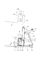
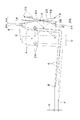
図面に基づいて、走行リフターは、機台9の中央部上に昇降体Sを昇降するリフト支柱Rを立設し、このリフト支柱Rの後側に操作ボックス17や、ハンドル18等を配置し、前記リフト支柱Rの左右両側部から前方へ張出するアウトリガー12を設けて、この前端部にモータによって駆動回転される前車輪11を設け、機台9後下方には左右一対のキャスター車輪10を設けて、これら前車輪11及びキャスター輪10の回転により床面を走行移動することができる。   Based on the drawings, the traveling lifter has a lift column R for raising and lowering the lifting body S on the central part of the machine base 9, and an operation box 17, a handle 18, etc. are arranged behind the lift column R. An outrigger 12 that projects forward from the left and right side portions of the lift column R is provided, and a front wheel 11 that is driven and rotated by a motor is provided at the front end portion. And the floor surface can be moved by the rotation of the front wheels 11 and the caster wheels 10.

前記リフト支柱Rは、機台9に固定のリフトタワー8と、該リフトタワー8内側で昇降する昇降タワー19とからなる2段伸縮形態として、この昇降タワー19を油圧シリンダ35で上昇させることで、昇降チェン20を介して吊着された昇降体Sを昇降させることができる。前記操作ボックス17内に搭載している油圧ユニットの油圧レバー36を操作することにより、油圧シリンダ35が伸縮して昇降体Sの昇降チェン20を駆動する形態である。昇降体Sは、リフトブラケット7に軸支のガイドロール21が昇降タワー19内方を円滑に昇降し、昇降タワー19の下部左右両外側に軸支のガイドロール37がリフトタワー8内方を円滑に昇降する構成にしてある。   The lift column R is a two-stage expansion / contraction form composed of a lift tower 8 fixed to the machine base 9 and a lift tower 19 that moves up and down inside the lift tower 8, and the lift tower 19 is lifted by a hydraulic cylinder 35. The lifting body S suspended through the lifting chain 20 can be lifted and lowered. By operating the hydraulic lever 36 of the hydraulic unit mounted in the operation box 17, the hydraulic cylinder 35 expands and contracts to drive the lifting chain 20 of the lifting body S. In the lifting body S, the guide roll 21 of the shaft support is smoothly moved up and down inside the lift tower 19 on the lift bracket 7, and the guide roll 37 of the shaft support is smoothly moved inside the lift tower 8 on both the left and right sides of the lower part of the lift tower 19. It is configured to move up and down.

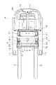
前記リフトブラケット7の前側にクロスリンク1,2からなるクロスリンク機構Kを設け、該クロスリンク1,2前端にフロントリンク4を取着し、このフロントリンク4にフォーク5を取着している。このクロスリンク機構Kの拡縮作動は、リフトブラケット7の左右中央部に設ける単一のシリンダ6の伸縮によって行われ、前記機台9に搭載のバッテリにより駆動される電動の油圧シリンダで行われる。尚、これらのシリンダは電動に限定するものではなく、油圧装置やネジ式の伸縮駆動であってもよい。   A cross link mechanism K including cross links 1 and 2 is provided on the front side of the lift bracket 7, a front link 4 is attached to the front ends of the cross links 1 and 2, and a fork 5 is attached to the front link 4. . The expansion / contraction operation of the cross link mechanism K is performed by expansion / contraction of a single cylinder 6 provided at the left and right center portion of the lift bracket 7, and is performed by an electric hydraulic cylinder driven by a battery mounted on the machine base 9. These cylinders are not limited to electric drive, but may be a hydraulic device or a screw type telescopic drive.

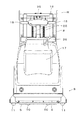
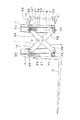
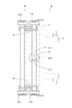
昇降体Sのクロスリンク機構Kは、正面視囲桁状のリフトブラケット7と、この前側に位置させる同形態のフロントリンク4との間をクロスリンク1,2で連結して拡縮する形態で、これらリフトブラケット7とフロントリンク4の左右両側部に配置し、各クロスリンク1,2は中間部を交差させてクロスピボット3で枢着して拡縮回動可能の構成とする。このクロスピボット3は左右のクロスリンク機構K部において独立形態に構成しているが、左右のクロスピボット3相互間にわたって横軸を設けて連結する形態とするも可能である。又、クロスリンク1,2は、前記クロスピボット3位置を、各リンク長さLの中間位置L/2よりも下端側の位置に設定している。このクロスピボット3の位置から各クロスリンク1,2の上端側の回動軸16,26位置までのリンクアーム長さを上部アーム1A,2Aとし、又、各クロスリンク1,2の下端側の支点軸14,24位置までのリンクアーム長さを下部アーム1B,2Bとして、両回動軸26,16の前後方向間隔AAよりも両支点軸14,24の前後方向間隔を短く設定してある。本実施例においては、各上部アーム1A,2Aを下部アーム1B,2Bよりも長く設定し、又、各下部アーム1B,2Bは同長(1B=2B)とし、上部アーム1A,2Aを同長(1A=2A)として設定している。   The cross link mechanism K of the lifting body S is a form in which the front view girder-shaped lift bracket 7 and the front link 4 of the same form positioned on the front side are connected by cross links 1 and 2 to expand and contract. The cross brackets 1 and 2 are arranged on both the left and right side portions of the lift bracket 7 and the front link 4, and each cross link 1 and 2 is configured to be capable of expanding and contracting by being pivotally attached to the cross pivot 3 with the middle portion crossed. The cross pivot 3 is configured in an independent form in the left and right cross link mechanisms K, but it is also possible to provide a form in which a horizontal axis is provided between the left and right cross pivots 3 for connection. In the cross links 1 and 2, the position of the cross pivot 3 is set at the lower end side of the intermediate position L / 2 of each link length L. The length of the link arm from the position of the cross pivot 3 to the position of the rotary shafts 16 and 26 on the upper end side of the cross links 1 and 2 is defined as the upper arms 1A and 2A. The link arm length to the position of the fulcrum shafts 14 and 24 is set as the lower arms 1B and 2B, and the distance between the fulcrum shafts 14 and 24 is set shorter than the distance AA between the rotation shafts 26 and 16. . In this embodiment, the upper arms 1A and 2A are set longer than the lower arms 1B and 2B, the lower arms 1B and 2B have the same length (1B = 2B), and the upper arms 1A and 2A have the same length. (1A = 2A) is set.

前記フロントリンク4とリフトブラケット7は、クロスリンク1,2を収縮した状態において、前後に重合して側面視若干上方開きの略平行状態となるが、これらフロントリンク4とリフトブラケット7の左右対向面には凹字形断面材からなる案内体15,25を形成し、これら案内体15,25に、前記上部アーム1A,2A上端部の回動軸16,26に回転自在のガイドロール27,28を摺動自在に案内させる。前記クロスリンク1,2の下部アーム1B,2Bの下端部は、支点軸14,24によって、各リフトブラケット7、フロントリンク4の下端部に枢着されるが、これら上部アーム1A,2Aの回動軸16,26のガイドロール27,28は、案内体15,25に嵌合した状態で、クロスリンク1,2のクロスピボット3周りの拡縮回動によって、これら案内体15,25の縦方向に沿って摺動して、開拡作動によりフロントリンク4を前方へ移動し、収縮作動により後方へ移動して、リフトブラケット7の前側位置へ接近させるものである。   The front link 4 and the lift bracket 7 overlap each other in the contracted state of the cross links 1 and 2 so that the front link 4 and the lift bracket 7 are substantially parallel to each other. Guide bodies 15 and 25 made of a concave cross-sectional material are formed on the surfaces, and guide rolls 27 and 28 that are rotatable on the rotation shafts 16 and 26 at the upper ends of the upper arms 1A and 2A are formed on the guide bodies 15 and 25, respectively. Is slidably guided. The lower ends of the lower arms 1B and 2B of the cross links 1 and 2 are pivotally attached to the lower ends of the lift brackets 7 and the front links 4 by fulcrum shafts 14 and 24, but the upper arms 1A and 2A are rotated. The guide rolls 27 and 28 of the moving shafts 16 and 26 are engaged with the guide bodies 15 and 25, and the longitudinal direction of the guide bodies 15 and 25 is caused by the expansion and contraction rotation around the cross pivot 3 of the cross links 1 and 2. The front link 4 is moved forward by the spreading operation, and moved rearward by the contraction operation to approach the front side position of the lift bracket 7.

前記リフトフォーク5は、側面視L形状に形成して、後側上端部をフロントリンク4上部のフォーク軸29の周りに回動自在、又は回動不能にして取付ける。このフォーク5の掬取面を形成する底部は、前記フロントリンク4の下端部よりも下位にして設定し、左右両側部のアウトリガー12間の幅間隔の内側に位置して前後移動するように構成している。このフォーク5の後側面は、フロントリンク4の下端部の横桟30に接当させるか、又は取付固定して、フォーク5の掬取作業時の姿勢を安定保持する。   The lift fork 5 is formed in an L shape in a side view, and the rear upper end portion is attached around the fork shaft 29 on the front link 4 so as to be rotatable or non-rotatable. The bottom portion forming the catching surface of the fork 5 is set lower than the lower end portion of the front link 4 and is configured to move back and forth while being positioned inside the width interval between the outriggers 12 on the left and right side portions. is doing. The rear side surface of the fork 5 is brought into contact with the horizontal rail 30 at the lower end portion of the front link 4 or is attached and fixed to stably maintain the posture of the fork 5 during the scraping operation.

前記クロスリンク1,2を拡縮作動するための掬取シリンダ6は、油圧回路からの油圧力によって、このスピンドル23が上方へ伸出されたり、収縮されるもので、このスピンドル23の上端部が、上部アーム2Aの回動軸16部に連結の連結片31にピン32で連結されて、これら掬取シリンダ6や、スピンドル23、ピン32、連結片31、及び回動軸16等が案内体15の中心線であるリヤリンク線Xに沿って伸縮作動するように構成している。又、クロスリンク1,2の拡縮作動においては、収縮作動側において掬取シリンダ6に大きい操作力を要するため、前記掬取シリンダ6を伸出作動において、クロスリンク1,2を収縮させて、フォーク5を後側へ引き寄せるように構成したものであるから、負荷に対応し易く、効率的な掬取作動を行わせることができる。   The take-up cylinder 6 for expanding and contracting the cross links 1 and 2 is such that the spindle 23 is extended upward or contracted by the hydraulic pressure from the hydraulic circuit. Further, the take-up cylinder 6, the spindle 23, the pin 32, the connecting piece 31, the turning shaft 16 and the like are connected to the connecting piece 31 connected to the turning shaft 16 part of the upper arm 2 </ b> A by a pin 32. It is configured to extend and contract along a rear link line X that is a center line of 15. Further, in the expansion / contraction operation of the cross links 1, 2, since a large operating force is required for the take-up cylinder 6 on the contraction operation side, the cross-links 1, 2 are contracted in the extension operation of the take-up cylinder 6. Since the fork 5 is configured to be pulled to the rear side, it is easy to cope with a load and an efficient scraping operation can be performed.

前記のようにクロスリンク1,2の拡縮によって前後移動されるフォーク5は、このクロスリンク1,2のフロントリンク4を支持する上部アーム1Aが下部アーム2Bよりも長く設定されているために、このクロスリンク1,2が開拡されて前側へ移動されるに伴って、底部の移動量Cよりも上部の移動量Dが大きく、フロントリンク4を前倒れの状態に傾斜させる。従って、前側へ移動して荷物を掬い込ませるときは、このフォーク5の前端部をE位置からF位置へ順次下動Hさせながら前進させるものである。このため、床面の荷物や、パレット等を掬うときは、フォーク5を前方下方に下降移動させながら、しかもこのフォーク5を床面に摺接するようにして推進させるものであるから、荷物下面への挿込を正確に行わせることができる。   As described above, the fork 5 that is moved back and forth by the expansion and contraction of the cross links 1 and 2 is set so that the upper arm 1A that supports the front link 4 of the cross links 1 and 2 is set longer than the lower arm 2B. As the cross links 1 and 2 are unfolded and moved to the front side, the upper movement amount D is larger than the bottom movement amount C, and the front link 4 is tilted forward. Therefore, when moving the front side and picking up the load, the fork 5 is moved forward while moving the front end of the fork 5 downward from the E position to the F position. For this reason, when picking up a load on the floor, a pallet, or the like, the fork 5 is pushed down and moved forward, and the fork 5 is slidably contacted with the floor. Can be inserted accurately.

このようにしてフォーク5の前進で掬い込ませた荷物を後側のリフトタワー8側へ引き寄せるときは、クロスリンク1,2は収縮作動されるため、上記とは逆の作動によって掬取作動される。即ち、フロントリンク4の下端部と上端部との後退量の差(D>C)によって、前傾姿勢から直立姿勢へ起こされるフロントリンク4の移動によって、下部位置Fのフォーク5が前上り位置Eへ上昇されて、前上り傾斜の姿勢となり、荷物の前側への脱出を阻止して、後側のフロントリンク4側への移動、掬込を行い易くし、安定した姿勢で後側へ引き寄せることができる。   Thus, when pulling the load that has been swallowed by the forward movement of the fork 5 toward the lift tower 8 on the rear side, the cross links 1 and 2 are contracted, so that they are scraped by the reverse operation to the above. The That is, the fork 5 at the lower position F is moved forward by the movement of the front link 4 caused from the forward tilted posture to the upright posture due to the difference in the retraction amount between the lower end portion and the upper end portion of the front link 4 (D> C). It is raised to E, and it becomes a posture of a front rising slope, prevents the luggage from escaping to the front side, makes it easy to move and pin the rear side of the front link 4, and draws it to the rear side in a stable posture. be able to.

1 クロスリンク
2 クロスリンク
3 クロスピボット
4 フロントリンク
5 フォーク
6 シリンダ
7 リフトブラケット
9 機台
10 車輪
11 車輪
12 アウトリガー
14 支点軸
15 案内体
16 回動軸
24 支点軸
25 案内体
26 回動軸
27 ガイドロール
28 ガイドロール
1A 上部アーム
1B 下部アーム
2A 上部アーム
2B 下部アーム
AA 前後方向間隔
BB 前後方向間隔
K クロスリンク機構
R リフト支柱
S 昇降体
DESCRIPTION OF SYMBOLS 1 Cross link 2 Cross link 3 Cross pivot 4 Front link 5 Fork 6 Cylinder 7 Lift bracket 9 Machine base 10 Wheel 11 Wheel 12 Outrigger 14 Supporting point shaft 15 Guide body 16 Turning shaft 24 Supporting shaft 25 Guide body 26 Turning shaft 27 Guide Roll 28 Guide roll 1A Upper arm 1B Lower arm 2A Upper arm 2B Lower arm AA Front-rear direction interval BB Front-rear direction interval K Cross-link mechanism R Lift strut S Elevator

Claims (2)

機台(9)の下方左右両端部から前方へ突出するアウトリガー(12)と、機台(9)から立設するリフト支柱(R)に沿って昇降自在の昇降体(S)を備え、該昇降体(S)前側には前方へ向け突出するフォーク(5)を取着し、前記アウトリガー(12)前端部と機台(9)下方の車輪(10),(11)で走行することのできるリーチ型走行リフターのリフトフォークであって、該昇降体(S)を、リフト支柱(R)側のリフトブラケット(7)とフォーク(5)側のフロントリンク(4)と、このリフトブラケット(7)及びフロントリンク(4)間を伸縮可能なクロスリンク機構(K)とで構成し、該クロスリンク機構(K)のクロスリンク(1),(2)下端部をリフトブラケット(7)とフロントリンク(4)との各々の下端部支点軸(14),(24)へ枢支し、クロスリンク(1),(2)上端部にはガイドロール(27),(28)を設け、両クロスリンク(1),(2)をクロスピボット(3)周りに回動させた際、ガイドロール(27),(28)がリフトブラケット(7)とフロントリンク(4)の縦方向の案内体(15),(25)に沿って摺動案内されるよう構成するとともに、両ガイドロール(27),(28)の回動軸(26),(16)の前後方向間隔(AA)よりも両支点軸(14),(24)の前後方向間隔(BB)を短く設定し、更に、クロスリンク(1),(2)の回動軸(16)と支点軸(14)との間を側面視においてリフト支柱(R)と略平行に配置した単一のシリンダ(6)で連結してなるリーチ型走行リフターのリフトフォーク。   An outrigger (12) protruding forward from the lower left and right ends of the machine base (9), and a lifting body (S) that can be raised and lowered along a lift column (R) standing from the machine base (9), A fork (5) projecting forward is attached to the front side of the lifting body (S), and the vehicle is driven by the front end of the outrigger (12) and the wheels (10), (11) below the machine base (9). A lift fork of a reach-type travel lifter that can be connected to a lift bracket (7) on the lift column (R) side, a front link (4) on the fork (5) side, and the lift bracket ( 7) and a cross link mechanism (K) that can extend and contract between the front link (4), and the lower ends of the cross links (1) and (2) of the cross link mechanism (K) are connected to the lift bracket (7). Lower end of each with front link (4) It is pivotally supported to the fulcrum shafts (14) and (24), and guide rolls (27) and (28) are provided at the upper ends of the cross links (1) and (2). When the guide rolls (27) and (28) are rotated around the cross pivot (3), the guide rolls (27) and (28) follow the longitudinal guide bodies (15) and (25) of the lift bracket (7) and the front link (4). The fulcrum shafts (14), (24) are configured so as to be slidably guided, and more than the distance (AA) in the front-rear direction (AA) of the rotation shafts (26), (16) of both guide rolls (27), (28). The front-rear direction interval (BB) is set to be short, and the distance between the pivot shaft (16) and the fulcrum shaft (14) of the cross links (1), (2) is substantially the same as the lift column (R) in a side view. Lift lift of reach type travel lifter connected by a single cylinder (6) arranged in parallel Over click. 下部アーム(1B)と下部アーム(2B)とを同長さとし、上部アーム(1A)と上部アーム(2A)とを同長さに設定してなる請求項1に記載のリーチ型走行リフターのリフトフォーク。   The lift of the reach type travel lifter according to claim 1, wherein the lower arm (1B) and the lower arm (2B) have the same length, and the upper arm (1A) and the upper arm (2A) have the same length. fork.
JP2011004448A 2011-01-13 2011-01-13 Lift fork of reach type traveling lifter Pending JP2012144343A (en)

Priority Applications (1)

Application Number Priority Date Filing Date Title
JP2011004448A JP2012144343A (en) 2011-01-13 2011-01-13 Lift fork of reach type traveling lifter

Applications Claiming Priority (1)

Application Number Priority Date Filing Date Title
JP2011004448A JP2012144343A (en) 2011-01-13 2011-01-13 Lift fork of reach type traveling lifter

Publications (1)

Publication Number Publication Date
JP2012144343A true JP2012144343A (en) 2012-08-02

Family

ID=46788343

Family Applications (1)

Application Number Title Priority Date Filing Date
JP2011004448A Pending JP2012144343A (en) 2011-01-13 2011-01-13 Lift fork of reach type traveling lifter

Country Status (1)

Country Link
JP (1) JP2012144343A (en)

Cited By (1)

* Cited by examiner, † Cited by third party
Publication number Priority date Publication date Assignee Title
CN111169928A (en) * 2020-02-21 2020-05-19 赫菲斯热处理系统江苏有限公司 A material fork module and a material truck

Cited By (1)

* Cited by examiner, † Cited by third party
Publication number Priority date Publication date Assignee Title
CN111169928A (en) * 2020-02-21 2020-05-19 赫菲斯热处理系统江苏有限公司 A material fork module and a material truck

Similar Documents

Publication Publication Date Title
CN202346697U (en) Fork scissor type hydraulic lifting and overturning mechanism
CN102648147B (en) A linkage system for a forklift truck
CN105523504B (en) Forklift
JP6455203B2 (en) Car body weight support device for crawler crane
JP2012056661A (en) Package transporting robot and method for controlling the robot
JP2013075606A (en) Platform of movable carriage
JP2012144343A (en) Lift fork of reach type traveling lifter
JP4215181B2 (en) Aircraft tow truck
JP2001213592A (en) Jack device for aerial work vehicles
JP2022176463A (en) Truck equipped with rail feeding device
JP6320140B2 (en) forklift
JP6485657B2 (en) Aerial work equipment
JP5202908B2 (en) Loading platform lifting device
JP6249059B1 (en) Trolley
JP6561574B2 (en) Mobile crane and method for raising or lowering an attachment in a mobile crane
JP7460680B2 (en) low lift truck
JP6807733B2 (en) Aerial work platform
JP4207856B2 (en) Crawler type traveling device
CN102501790A (en) A strut device and carriage structure
JP2013055897A (en) Posture controlling device for combine harvester
JP2007297143A (en) Aerial work platform
JP4665230B2 (en) Work vehicle
JP2024148905A (en) Work vehicle
JP2013049533A (en) Forklift
JP2018016316A (en) Trolley