JP2012144338A - Passenger conveyor - Google Patents
Passenger conveyor Download PDFInfo
- Publication number
- JP2012144338A JP2012144338A JP2011004207A JP2011004207A JP2012144338A JP 2012144338 A JP2012144338 A JP 2012144338A JP 2011004207 A JP2011004207 A JP 2011004207A JP 2011004207 A JP2011004207 A JP 2011004207A JP 2012144338 A JP2012144338 A JP 2012144338A
- Authority
- JP
- Japan
- Prior art keywords
- truss
- gusset plate
- fastened
- fastening hole
- fastening
- Prior art date
- Legal status (The legal status is an assumption and is not a legal conclusion. Google has not performed a legal analysis and makes no representation as to the accuracy of the status listed.)
- Pending
Links
- 238000004519 manufacturing process Methods 0.000 abstract description 8
- 238000003466 welding Methods 0.000 description 18
- 238000009434 installation Methods 0.000 description 11
- 238000005304 joining Methods 0.000 description 5
- 238000000034 method Methods 0.000 description 5
- 239000000428 dust Substances 0.000 description 4
- 230000002411 adverse Effects 0.000 description 2
- 230000000694 effects Effects 0.000 description 2
- 239000003517 fume Substances 0.000 description 2
- 238000012986 modification Methods 0.000 description 2
- 230000004048 modification Effects 0.000 description 2
- 230000015572 biosynthetic process Effects 0.000 description 1
- 238000007796 conventional method Methods 0.000 description 1
Images

Landscapes
- Escalators And Moving Walkways (AREA)
Abstract
Description
本発明の実施形態は、乗客コンベアに関する。 Embodiments of the present invention relate to a passenger conveyor.
エスカレータ等の乗客コンベアにおけるトラス製作に際しては、トラスにトラス接続部用梁を接合することが一般に行われている。そして、従来は、トラスとなるアングル材に対してトラス接続部用梁となるアングル材を直接溶接することにより、トラスにトラス接続部用梁を接合してトラスを形成していた。 When a truss is manufactured on a passenger conveyor such as an escalator, it is generally performed to join a truss connecting beam to the truss. Conventionally, the truss is formed by directly joining the truss connecting portion beam to the truss by directly welding the truss connecting portion beam to the truss angle member.
しかしながら、従来より行われてきたトラスとトラス接続部用梁との溶接接合によるトラスの形成方法においては、溶接の熱によるトラス歪みが発生するおそれがある。また溶接時に粉塵や紫外線が発生するため環境や人体に悪影響を及ぼす可能性がある。しかも溶接による接合は安定した品質を維持するのに熟練した技能が必要であり、製作工数も多い。また、トラス解体時に溶断する必要があり、種々の問題が発生する可能性がある。 However, in the conventional method for forming a truss by welding between the truss and the beam for the truss connection portion, there is a risk of truss distortion due to the heat of welding. In addition, dust and ultraviolet rays are generated during welding, which may adversely affect the environment and the human body. In addition, joining by welding requires skilled skills to maintain stable quality, and requires a large number of manufacturing steps. Moreover, it is necessary to blow at the time of truss dismantling, and various problems may occur.
本発明の実施態様は、ボルト締結化することにより、安定した品質を確保でき、技能習得も容易であり、製作工数も低減される乗客コンベアを提供することにある。 An embodiment of the present invention is to provide a passenger conveyor that can secure stable quality, can easily acquire skills, and can reduce the number of manufacturing steps by fastening with bolts.
本発明の実施形態に係る乗客コンベアは、トラスとトラスに接続されるトラス接続部材とにおいて、トラス接続部材にガセットプレートを取り付け、トラス接続部材を取り付けたガセットプレートとトラスとを締結具にて締結してトラスにトラス接続部材を固定することにより、トラスの少なくとも一部が形成されていることを特徴とする。 A passenger conveyor according to an embodiment of the present invention includes a truss and a truss connecting member connected to the truss. Then, by fixing the truss connecting member to the truss, at least a part of the truss is formed.
以下、本発明の実施例に係るエスカレータについて、図面を参照して説明する。 Hereinafter, escalators according to embodiments of the present invention will be described with reference to the drawings.
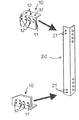
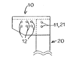
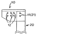
図1において、10はガセットプレートであり、20はトラス接続部材の一種であるトラス接続部用梁である。このガセットプレート10は、図2に示すように、トラス接続部用梁20に溶接により接合固定されている。このトラス接続部用梁20にガセットプレート10を取り付ける溶接作業は、製造工場において行うことができるので、エスカレータ設置現場では行う必要はない。
In FIG. 1, 10 is a gusset plate, and 20 is a beam for a truss connection part which is a kind of truss connection member. As shown in FIG. 2, the
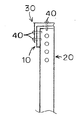
前記ガセットプレート10には、後述するトラス30とガセットプレート10とトラス接続部用梁20とを締結する際に使用する締結用穴11が形成されている。また、トラス接続部用梁20にもトラスとガセットプレートとトラス接続部用梁とを締結する際に使用する締結用穴21が形成されている。したがって、ガセットプレート10とトラス接続部用梁20とを溶接する際に、ガセットプレート10における締結用穴11とトラス接続部用梁20における締結用穴21とを一致させておく。さらに、ガセットプレート10には、トラス30とガセットプレート10とを締結する際に使用する締結用穴12が形成されている。
The
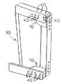
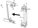
図3において、30は一部のトラスであり、トラス30には、トラス30とガセットプレート10とトラス接続部用梁20とを締結する際に使用する締結用穴31が形成されている。また、トラス30には、トラス30とガセットプレート10とを締結する際に使用する締結用穴32が形成されている。
In FIG. 3,
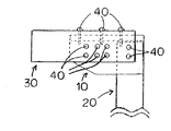
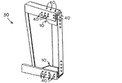
そして、エスカレータ設置現場におけるトラス形成時において、締結用穴11、21、31を一致させ、この締結穴にハックボルト40(HUCK BOLT 商品名)(ファスニングシステム)を通して締結する。また、締結用穴12、32を一致させ、この締結穴にハックボルト40(HUCK BOLT 商品名)を通して締結する。そうすると、トラス30とトラス接続部用梁20とがガセットプレート10を介してハックボルト40(HUCK BOLT 商品名)により締結固定される。
At the time of truss formation at the escalator installation site, the
以上のように構成したことにより、エスカレータ設置現場におけるトラス30とトラス接続部用梁20との接合工数が大幅に短縮される。また、従来、エスカレータ設置現場において行われていた溶接とは異なり、作業習熟が容易である。さらに、エスカレータ設置現場において溶接をしないので、人体に有害な粉塵(ヒューム)や、紫外線が一切発生しない。
With the configuration described above, the number of man-hours for joining the
本実施例では、トラス接続部用梁のみとなっているが、エスカレータトラスの他の部分にガセットプレートを介してハックボルト(HUCK BOLT 商品名)により締結固定する方法を採用しても同等の効果が得られる。また、本実施例では、ハックボルト(HUCK BOLT 商品名)を使用しているが、緩むことのない、例えばロックボルト等の締結具を使用してもよい。さらに、本実施例では、締結用穴を形成して締結する方法を説明したが、締結用穴を形成せず、挟み込みにより締結してもよい。 In this example, only the beam for the truss connection part is used, but the same effect can be obtained even if a method of fastening and fixing to the other part of the escalator truss with a hack bolt (HUCK BOLT product name) via a gusset plate is used. Is obtained. Moreover, although the hack bolt (HUCK BOLT brand name) is used in a present Example, you may use fasteners, such as a lock bolt, which does not loosen. Further, in the present embodiment, the method of fastening by forming the fastening hole has been described. However, the fastening hole may not be formed and fastening may be performed by pinching.
本発明のいくつかの実施形態を説明したが、これら実施形態は、例として提示したものであり、発明の範囲を限定することは意図していない。これら実施形態は、その他の様々な形態で実施されることが可能であり、発明の要旨を逸脱しない範囲で、種々の省略、置き換え、変更を行うことができる。これら実施形態やその変形は、発明の範囲や要旨に含まれると同様に、特許請求の範囲に記載された発明とその均等の範囲に含まれるものである。 Although several embodiments of the present invention have been described, these embodiments are presented by way of example and are not intended to limit the scope of the invention. These embodiments can be implemented in various other forms, and various omissions, replacements, and changes can be made without departing from the spirit of the invention. These embodiments and their modifications are included in the scope and gist of the invention, and are also included in the invention described in the claims and the equivalents thereof.
10・・ガセットプレート
11・・締結用穴
12・・締結用穴
20・・トラス接続部用梁
21・・締結用穴
30・・トラス
31・・締結用穴
32・・締結用穴
40・・ハックボルト
10. ·
本発明の実施形態は、乗客コンベアに関する。 Embodiments of the present invention relate to a passenger conveyor.
エスカレータ等の乗客コンベアにおけるトラスの製作に際しては、設置現場にてトラスにトラス接続部用梁を直接溶接することで接合している。 Upon fabrication of the truss in the passenger conveyor such as an escalator is joined by welding the beam trusses connecting portion truss at the installation site directly.
しかしながら、従来より行われてきたトラスとトラス接続部用梁との溶接接合によるトラスの形成方法においては、溶接の熱によりトラスに歪みが発生するおそれがある。また溶接時に粉塵や紫外線が発生するため、環境や人体に悪影響を及ぼす可能性がある。しかも溶接による接合は、安定した品質を維持するために熟練した技能が必要であり、製作工数も多い。また、トラスの解体時に溶断する必要があり、種々の問題が発生する可能性がある。 However, in the method of forming a truss by welding with has been done conventionally trusses and truss connection portion beam, there is a possibility that distortion occurs more truss for welding heat. Further, since the dust and ultraviolet rays generated during welding, it can adversely affect the environment and the human body. Moreover joining by welding skills skilled in order to maintain a stable quality is required, manufacturing steps is large. Moreover, it is necessary to blow when the truss is dismantled, which may cause various problems.
本発明の実施態様は、ボルトによる締結を採用することにより、安定した品質を確保でき、技能習得も容易であり、製作工数も低減されるトラスを備えた乗客コンベアを提供することにある。 An embodiment of the present invention is to provide a passenger conveyor provided with a truss that can secure stable quality, easily acquire skills, and reduce the number of manufacturing steps by adopting fastening with bolts.
本発明の実施形態に係る乗客コンベアは、トラスと前記トラスに接続されたトラス接続部材とを具備する乗客コンベアにおいて、前記トラス接続部材に取り付けられたガセットプレートと、前記ガセットプレートと前記トラスとを締結する締結具とを具備することを特徴とする。 Passenger conveyor according to the embodiment of the present invention is a passenger conveyor comprising a truss connecting member connected to said truss truss, a gusset plate attached to the truss connecting member, and the said gusset plate truss It and a fastener for fastening and said Rukoto.
以下、本発明の実施例に係るエスカレータについて、図面を参照して説明する。 Hereinafter, escalators according to embodiments of the present invention will be described with reference to the drawings.
図1において、10はガセットプレートであり、20はトラス接続部材の一種であるトラス接続部用梁である。図2に示すように、ガセットプレート10はトラス接続部用梁20に、例えば溶接により接合固定されている。このトラス接続部用梁20にガセットプレート10を取り付ける溶接作業は、製造工場において行うことができるので、エスカレータ設置現場では行う必要はない。
In FIG. 1, 10 is a gusset plate, and 20 is a beam for a truss connection part which is a kind of truss connection member. As shown in FIG. 2, the
ガセットプレート10には、後述するトラス30とガセットプレート10とトラス接続部用梁20とを締結する際に使用する締結用穴11が形成されている。また、トラス接続部用梁20にもトラス30とガセットプレート10とトラス接続部用梁20とを締結する際に使用する締結用穴21が形成されている。したがって、ガセットプレート10とトラス接続部用梁20とを、例えば溶接する際に、ガセットプレート10における締結用穴11とトラス接続部用梁20における締結用穴21とを一致させておく。さらに、ガセットプレート10には、トラス30とガセットプレート10とを締結する際に使用する締結用穴12が形成されている。
The
図3において、30はトラスの一部であり、トラス30には、トラス30とガセットプレート10とトラス接続部用梁20とを締結する際に使用する締結用穴31が形成されている。また、トラス30には、トラス30とガセットプレート10とを締結する際に使用する締結用穴32が形成されている。
In FIG. 3,
そして、エスカレータ設置現場にて、締結用穴11(21)、31を一致させ、これら締結用穴11(21)、31にハックボルト40(HUCK BOLT 商品名)(ファスニングシステム)を通して締結する。また、締結用穴12、32を一致させ、これらの締結用穴12、32にハックボルト40(HUCK BOLT 商品名)を通して締結する。そうすると、図4に示すように、トラス30とトラス接続部用梁20とがガセットプレート10を介してハックボルト40(HUCK BOLT 商品名)により締結固定される。図5に、トラス30にトラス接続部用梁20を締結した状態の一部拡大正面図を示す。また、図6に、トラスにトラス接続部用梁を締結した状態の一部拡大右側面図を示す。
以上のように構成したことにより、エスカレータ設置現場におけるトラス30とトラス接続部用梁20との接合工数が大幅に短縮される。また、従来、エスカレータ設置現場において行われていた溶接とは異なり、作業習熟が容易である。さらに、エスカレータ設置現場において溶接をしないので、人体に有害な粉塵(ヒューム)や、紫外線が一切発生しない。
Then, in the escalator installation site, fastening hole 11 (21), 31 to match the, these fastening hole 11 (21), to conclude through 31 to hack bolt 40 (HUCK BOLT trade name) (fastening system) . In addition, to match the fastening holes 12 and 32, fastened to the fastening holes 12, 32 of these through the hack bolt 40 (HUCK BOLT trade name). Then, as shown in FIG. 4, the
With the configuration described above, the number of man-hours for joining the
本実施例では、トラス接続部用梁のみとなっているが、エスカレータトラスの他の部分にガセットプレートを介してハックボルト(HUCK BOLT 商品名)により締結固定する方法を採用しても同等の効果が得られる。また、本実施例では、ハックボルト(HUCK BOLT 商品名)を使用しているが、緩むことのない、例えばロックボルト等の締結具を使用してもよい。さらに、本実施例では、締結用穴を形成して締結する方法を説明したが、締結用穴を形成せず、挟み込みにより締結してもよい。 In this example, only the beam for the truss connection part is used, but the same effect can be obtained even if a method of fastening and fixing to the other part of the escalator truss with a hack bolt (HUCK BOLT product name) via a gusset plate is used. Is obtained. Moreover, although the hack bolt (HUCK BOLT brand name) is used in a present Example, you may use fasteners, such as a lock bolt, which does not loosen. Further, in the present embodiment, the method of fastening by forming the fastening hole has been described. However, the fastening hole may not be formed and fastening may be performed by pinching.
本発明のいくつかの実施形態を説明したが、これら実施形態は、例として提示したものであり、発明の範囲を限定することは意図していない。これら実施形態は、その他の様々な形態で実施されることが可能であり、発明の要旨を逸脱しない範囲で、種々の省略、置き換え、変更を行うことができる。これら実施形態やその変形は、発明の範囲や要旨に含まれると同様に、特許請求の範囲に記載された発明とその均等の範囲に含まれるものである。 Although several embodiments of the present invention have been described, these embodiments are presented by way of example and are not intended to limit the scope of the invention. These embodiments can be implemented in various other forms, and various omissions, replacements, and changes can be made without departing from the spirit of the invention. These embodiments and their modifications are included in the scope and gist of the invention, and are also included in the invention described in the claims and the equivalents thereof.
10・・ガセットプレート
11・・締結用穴
12・・締結用穴
20・・トラス接続部用梁
21・・締結用穴
30・・トラス
31・・締結用穴
32・・締結用穴
40・・ハックボルト
10. ·
Claims (5)
Priority Applications (2)
| Application Number | Priority Date | Filing Date | Title |
|---|---|---|---|
| JP2011004207A JP2012144338A (en) | 2011-01-12 | 2011-01-12 | Passenger conveyor |
| CN 201120482732 CN202609746U (en) | 2011-01-12 | 2011-11-28 | Passenger conveyor |
Applications Claiming Priority (1)
| Application Number | Priority Date | Filing Date | Title |
|---|---|---|---|
| JP2011004207A JP2012144338A (en) | 2011-01-12 | 2011-01-12 | Passenger conveyor |
Publications (1)
| Publication Number | Publication Date |
|---|---|
| JP2012144338A true JP2012144338A (en) | 2012-08-02 |
Family
ID=46788338
Family Applications (1)
| Application Number | Title | Priority Date | Filing Date |
|---|---|---|---|
| JP2011004207A Pending JP2012144338A (en) | 2011-01-12 | 2011-01-12 | Passenger conveyor |
Country Status (2)
| Country | Link |
|---|---|
| JP (1) | JP2012144338A (en) |
| CN (1) | CN202609746U (en) |
Cited By (3)
| Publication number | Priority date | Publication date | Assignee | Title |
|---|---|---|---|---|
| CN104003281A (en) * | 2014-06-11 | 2014-08-27 | 日立电梯(广州)自动扶梯有限公司 | Overlap-connecting structure of escalator truss |
| JP2017514772A (en) * | 2014-04-30 | 2017-06-08 | インベンテイオ・アクテイエンゲゼルシヤフトInventio Aktiengesellschaft | Truck system for escalators or moving walkways |
| EP3932845A1 (en) * | 2020-06-30 | 2022-01-05 | TK Elevator Innovation and Operations GmbH | Connecting port of a support for an escalator or a moving walkway |
Families Citing this family (2)
| Publication number | Priority date | Publication date | Assignee | Title |
|---|---|---|---|---|
| DE102015224549A1 (en) * | 2015-12-08 | 2017-06-08 | Thyssenkrupp Ag | Escalator or moving walkway support construction and method of manufacturing at least one subsegment of an escalator or moving walkway support structure |
| CN106006335B (en) * | 2016-07-25 | 2018-01-16 | 森赫电梯股份有限公司 | A kind of escalator and moving sidewalk support body attachment means |
Citations (3)
| Publication number | Priority date | Publication date | Assignee | Title |
|---|---|---|---|---|
| JPS53129090U (en) * | 1977-03-22 | 1978-10-13 | ||
| JPH04203611A (en) * | 1990-11-30 | 1992-07-24 | Sumitomo Light Metal Ind Ltd | Honeycomb panel welding method |
| JPH06144761A (en) * | 1992-11-07 | 1994-05-24 | Sumitomo Heavy Ind Ltd | Intermediate frame setting method for moving footpath |
-
2011
- 2011-01-12 JP JP2011004207A patent/JP2012144338A/en active Pending
- 2011-11-28 CN CN 201120482732 patent/CN202609746U/en not_active Expired - Lifetime
Patent Citations (3)
| Publication number | Priority date | Publication date | Assignee | Title |
|---|---|---|---|---|
| JPS53129090U (en) * | 1977-03-22 | 1978-10-13 | ||
| JPH04203611A (en) * | 1990-11-30 | 1992-07-24 | Sumitomo Light Metal Ind Ltd | Honeycomb panel welding method |
| JPH06144761A (en) * | 1992-11-07 | 1994-05-24 | Sumitomo Heavy Ind Ltd | Intermediate frame setting method for moving footpath |
Cited By (3)
| Publication number | Priority date | Publication date | Assignee | Title |
|---|---|---|---|---|
| JP2017514772A (en) * | 2014-04-30 | 2017-06-08 | インベンテイオ・アクテイエンゲゼルシヤフトInventio Aktiengesellschaft | Truck system for escalators or moving walkways |
| CN104003281A (en) * | 2014-06-11 | 2014-08-27 | 日立电梯(广州)自动扶梯有限公司 | Overlap-connecting structure of escalator truss |
| EP3932845A1 (en) * | 2020-06-30 | 2022-01-05 | TK Elevator Innovation and Operations GmbH | Connecting port of a support for an escalator or a moving walkway |
Also Published As
| Publication number | Publication date |
|---|---|
| CN202609746U (en) | 2012-12-19 |
Similar Documents
| Publication | Publication Date | Title |
|---|---|---|
| JP2012144338A (en) | Passenger conveyor | |
| US8727428B2 (en) | Front part body structure of vehicle | |
| JP2015027838A (en) | Body manufacturing method | |
| BRPI0820563A2 (en) | coupling element for joining two longitudinal reinforcement elements | |
| TW537985B (en) | Method of manufacturing side panel in vehicle body | |
| ATE516197T1 (en) | INTERMEDIATE WALL ARRANGEMENT | |
| KR20160015169A (en) | Vehicle resin back door structure | |
| KR20190068128A (en) | Mounting unit | |
| KR101587948B1 (en) | Canopy structure which have advantages of maintaining and repairing the frame | |
| JP3754115B2 (en) | Rail vehicle production method | |
| CN104085278B (en) | A kind of method improving vehicle dormer window reinforcing plate assembly precision | |
| CA2970594C (en) | Method and device for assembling automobile body | |
| KR101488211B1 (en) | Stud bolt unit | |
| JP2021014233A (en) | Stud plate, vehicle frame, and method for manufacturing stud plate | |
| RU2432279C2 (en) | Rolling stock frame | |
| JP2015217899A (en) | Vehicle body structure | |
| CN203793434U (en) | Fender installation structure assembly | |
| JP4671409B2 (en) | STRUCTURE, STRUCTURAL COMPONENT AND METHOD FOR PRODUCING STRUCTURE | |
| CN214940591U (en) | Excavator and its main beam frame | |
| CN106938668A (en) | Vehicle body front girder module and assembling method thereof | |
| JP2003194021A (en) | Bolt joint structure for members, nut and metal fitting | |
| US20160068048A1 (en) | Windscreen Frame Assembly for Passenger Service Vehicle | |
| JP2001260951A (en) | Component structure | |
| JP2009084930A (en) | Composite structure made of steel and concrete | |
| KR20200041111A (en) | Golf game system booth |
Legal Events
| Date | Code | Title | Description |
|---|---|---|---|
| A621 | Written request for application examination |
Free format text: JAPANESE INTERMEDIATE CODE: A621 Effective date: 20130709 |
|
| A977 | Report on retrieval |
Free format text: JAPANESE INTERMEDIATE CODE: A971007 Effective date: 20140604 |
|
| A131 | Notification of reasons for refusal |
Free format text: JAPANESE INTERMEDIATE CODE: A131 Effective date: 20140610 |
|
| A02 | Decision of refusal |
Free format text: JAPANESE INTERMEDIATE CODE: A02 Effective date: 20141111 |