JP2012144227A - Mounting structure of electric power control device - Google Patents
Mounting structure of electric power control device Download PDFInfo
- Publication number
- JP2012144227A JP2012144227A JP2011006265A JP2011006265A JP2012144227A JP 2012144227 A JP2012144227 A JP 2012144227A JP 2011006265 A JP2011006265 A JP 2011006265A JP 2011006265 A JP2011006265 A JP 2011006265A JP 2012144227 A JP2012144227 A JP 2012144227A
- Authority
- JP
- Japan
- Prior art keywords
- power control
- control device
- vehicle
- motor
- motor case
- Prior art date
- Legal status (The legal status is an assumption and is not a legal conclusion. Google has not performed a legal analysis and makes no representation as to the accuracy of the status listed.)
- Granted
Links
Images


Classifications
-
- Y—GENERAL TAGGING OF NEW TECHNOLOGICAL DEVELOPMENTS; GENERAL TAGGING OF CROSS-SECTIONAL TECHNOLOGIES SPANNING OVER SEVERAL SECTIONS OF THE IPC; TECHNICAL SUBJECTS COVERED BY FORMER USPC CROSS-REFERENCE ART COLLECTIONS [XRACs] AND DIGESTS
- Y02—TECHNOLOGIES OR APPLICATIONS FOR MITIGATION OR ADAPTATION AGAINST CLIMATE CHANGE
- Y02T—CLIMATE CHANGE MITIGATION TECHNOLOGIES RELATED TO TRANSPORTATION
- Y02T10/00—Road transport of goods or passengers
- Y02T10/60—Other road transportation technologies with climate change mitigation effect
- Y02T10/70—Energy storage systems for electromobility, e.g. batteries
Landscapes
- Arrangement Or Mounting Of Propulsion Units For Vehicles (AREA)
- Electric Propulsion And Braking For Vehicles (AREA)
Abstract
Description
本発明は、車両のモータルームに電力制御装置を搭載するための電力制御装置の搭載構造に関する。 The present invention relates to a mounting structure of a power control device for mounting a power control device in a motor room of a vehicle.
従来から、走行用電動モータを制御するための電力制御装置が走行用電動モータと共にモータルーム(エンジンコンパートメントとも呼ばれる)内に搭載された電気自動車及びエンジンを有するハイブリッド自動車が知られている。電力制御装置は、大電力の電気エネルギーで車両を駆動するため、パワーモジュール、リアクトル、コンデンサ等を内蔵することから、補機用バッテリに比べて重量・体格とも大型である。このような電力制御装置をモータルームに搭載するためには、補機用バッテリの搭載メンバに比べて強度の高い搭載メンバが用いられ、モータルームのフレームやボディの一部を構成するサイドメンバ上であって、モータケースよりも高い位置に固定することが一般的である。 Conventionally, a hybrid vehicle having an electric vehicle and an engine in which a power control device for controlling the electric motor for traveling is mounted in a motor room (also called an engine compartment) together with the electric motor for traveling is known. Since the power control device drives the vehicle with high-power electric energy and incorporates a power module, a reactor, a capacitor, and the like, the power control device is larger in weight and size than the auxiliary battery. In order to mount such a power control device in the motor room, a mounting member having a higher strength than that of the auxiliary battery mounting member is used, and on the side member constituting a part of the frame or body of the motor room. And it is common to fix to a position higher than a motor case.
従来の搭載方法では車両が地上の固定物や他車両と衝突した場合、電力制御装置の前端部に障害物が干渉して電力制御装置に衝突入力が作用すると、サイドメンバやラジエータサポートなどのボディ部品に固定されていた搭載メンバの固定点に回転モーメントやせん断応力などの外力が加わることで搭載メンバは後方に回転する。これにより、電力制御装置が後方に後退し、障害物と電力制御装置との干渉を低減することで電力制御装置の損傷低減が図れている。 In the conventional mounting method, when a vehicle collides with a stationary object or other vehicle on the ground, if an obstacle interferes with the front end of the power control device and a collision input acts on the power control device, the body such as the side member or radiator support When an external force such as a rotational moment or shear stress is applied to the fixing point of the mounting member fixed to the component, the mounting member rotates backward. As a result, the power control device moves backward, and the interference between the obstacle and the power control device is reduced, thereby reducing damage to the power control device.
しかしながら、電力制御装置の後方側に他の車両搭載機器が配置されている場合には、電力制御装置と当該車両搭載機器とが干渉する場合がある。そこで、特許文献1には、車両の衝突時においても電力制御装置が他の車両搭載機器との衝突を避けるために、電力制御装置を載置台に搭載すると共に、載置台を案内部材の上に取り付けることで衝突時の他の車両搭載機器との干渉を低減する技術が開示されている。一方、上述したように電力制御装置が補機バッテリに比べて大型であるため、特許文献1の搭載構造では、必要な強度を得るためにブラケットを介して車両前方部のボディへ固定する必要があり、取り付け場所が制限されていた。そこで、特許文献2には、案内部材を使用しない電力制御装置と電動圧縮機の配置構造が開示されている。 However, when another vehicle-mounted device is arranged on the rear side of the power control device, the power control device and the vehicle-mounted device may interfere with each other. Therefore, in Patent Document 1, the power control device is mounted on the mounting table and the mounting table is placed on the guide member so that the power control device avoids a collision with other on-vehicle equipment even in the event of a vehicle collision. A technique for reducing interference with other on-vehicle equipment at the time of collision by mounting is disclosed. On the other hand, as described above, since the power control device is larger than the auxiliary battery, in the mounting structure of Patent Document 1, it is necessary to fix to the body in the front part of the vehicle via the bracket in order to obtain the required strength. Yes, the installation location was limited. Therefore, Patent Document 2 discloses an arrangement structure of an electric power control device and an electric compressor that do not use a guide member.
図6は、特許文献2に記載された従来のハイブリッド自動車110における電動圧縮機125と電力制御装置(パワーコントロールユニット:PCU)117の配置構造を示している。モータルーム112には、走行駆動源としてのエンジン114と、発電機としてのモータジェネレータ115と、別の走行駆動源としての走行用電動モータ116と、走行用電動モータ116上に配置されたPCU117と、PCUケース118に取付座122を介して固定された電動圧縮機125と、空調機を構成するコンデンサ126、レシーバ127,膨張弁及びエバポレータを備えたクーリングユニット128と、これらを接続する配管(図示せず)と、が配置されている。ここで、PCU117は、半導体や基板等の電子部品から構成されるPCU本体と、バッテリの電圧を昇圧させるバッテリ電圧昇圧回路120と、昇圧した直流高電圧電力の供給を受けて走行用電動モータを駆動するインバータ119と、電圧平滑用のコンデンサ21と、を有している。このような構成にすることで、案内部材を使用しない配置構造が実現されている。
FIG. 6 shows an arrangement structure of the
さらに、特許文献2の搭載構造では、電動圧縮機の電力と比較して大電力を扱う電力制御装置の強度を電動圧縮機の強度より大きくすることにより走行用電動モータ上部に電力制御装置を取り付け、走行用電動モータ上部の後方寄りに電動圧縮機を配置することを可能とし、電力制御装置の取り付け場所の制限を緩和している。 Furthermore, in the mounting structure of Patent Document 2, the power control device is attached to the upper part of the electric motor for traveling by making the strength of the power control device that handles large power larger than the strength of the electric compressor as compared with the power of the electric compressor. The electric compressor can be disposed near the rear of the upper portion of the electric motor for traveling, and the restriction on the installation place of the power control device is eased.
上述した特許文献1,2において、車両に対して入力される衝突エネルギーが大きい場合には、モータルームのサイドメンバに大きな変形が生じ、特に特許文献2のような構造では、電力制御装置と電動圧縮機が干渉するだけでなく、電動圧縮機がモータルームと車室を遮る隔壁と干渉して車室の変形が発生することになる。このような大きな衝突エネルギーに対処するためには、サイドメンバの強度を増やすだけではなく、走行用電動モータケース、フロアアンダーメンバ、トーボード及びフロントピラー等の強度も有効に利用して効率良くエネルギーを受け止めることが望まれる。 In Patent Documents 1 and 2 described above, when the collision energy input to the vehicle is large, a large deformation occurs in the side member of the motor room. Not only does the compressor interfere, but the electric compressor interferes with the partition that blocks the motor room and the passenger compartment, resulting in deformation of the passenger compartment. In order to cope with such a large collision energy, not only the strength of the side member is increased, but also the strength of the electric motor case for traveling, the floor under member, the toe board, the front pillar, etc. is effectively used to efficiently store the energy. It is desirable to take it.
そこで、本発明に係る電力制御装置の搭載構造は、走行用電動モータケース上に電力制御装置を固定する構造において、サイドメンバの強度と走行用電動モータケースとの強度を利用することで、車両の衝突時等においても、電力制御装置が他の搭載機器と干渉することを抑制し、電力制御装置等が損傷すること抑制可能な電力制御装置の搭載構造を提供することを目的とする。 Therefore, the mounting structure of the power control device according to the present invention is a structure in which the power control device is fixed on the traveling electric motor case, and by using the strength of the side member and the traveling electric motor case, the vehicle It is an object of the present invention to provide a mounting structure for a power control device that can prevent the power control device from interfering with other mounted devices even during a collision of the power control device and suppress damage to the power control device or the like.
以上のような目的を達成するために、本発明に係る電力制御装置の搭載構造は、バッテリから電力の供給を受け、走行用電動モータを制御する電力制御装置を、車両のモータルームに搭載するための電力制御装置の搭載構造において、電力制御装置は走行用電動モータを収容するモータケースの上部、かつ、車両後方寄りに配置され、モータルームと車室とを仕切る隔壁から電力制御装置の後方端までの距離が、モータケース後方端から隔壁までの距離よりも長くなるように電力制御装置をモータケース上に配置したことを特徴とするこのような構成にすることにより、電力制御装置の見かけ上の長さを低減すると共に、衝突時における衝突荷重をモータケースが受け持つことにより電力制御装置の損傷を軽減することが可能となる。 In order to achieve the above object, the power control device mounting structure according to the present invention mounts a power control device that receives power supplied from a battery and controls an electric motor for traveling in a motor room of a vehicle. In the mounting structure of the electric power control device for the electric power control device, the electric power control device is arranged at the upper part of the motor case that accommodates the electric motor for traveling and near the rear of the vehicle, and from the partition that partitions the motor room and the passenger compartment from the rear of the electric power control device By adopting such a configuration, the power control device is arranged on the motor case so that the distance to the end is longer than the distance from the rear end of the motor case to the partition wall. It is possible to reduce the upper length and reduce the damage of the power control device by the motor case handling the collision load at the time of collision.
また、本発明に係る電力制御装置の搭載構造において、電力制御装置は、車両前方からの衝突荷重を避けるため、モータケースの前方端から予め決められた距離だけ後方に配置することを特徴とする。この搭載構造は、電力制御装置をモータケースの先端から予め距離だけ後方に配置するだけでなく、モータケースの前方側に突起物となる補機を配置することにより、同様の効果を発揮することが可能となる。 In the power control device mounting structure according to the present invention, the power control device is arranged behind the front end of the motor case by a predetermined distance in order to avoid a collision load from the front of the vehicle. . This mounting structure not only arranges the power control device a distance away from the tip of the motor case in advance, but also exhibits the same effect by arranging an auxiliary device that becomes a projection on the front side of the motor case. Is possible.
また、本発明に係る電力制御装置の搭載構造において、車両前方からの衝突荷重を受けることによりモータルーム前方の構造体が変形すると共に、モータケースが隔壁に接触するまで車両後方に移動する場合であっても、隔壁から電力制御装置の後方端までの距離は、電力制御装置後部と隔壁上部との接触を防止する距離であることを特徴とする。このように配置では、電力制御装置の後方端にはパワーケーブルが接続されるため、隔壁とパワーケーブルとのクリアランスを確保することは、装置の安全性を高める上で重要である。特に、衝突時において、電力制御装置内部で急速放電を実行させるためには装置の正常作動を維持することが必要である。 In the mounting structure of the power control device according to the present invention, the structure in front of the motor room is deformed by receiving a collision load from the front of the vehicle, and the motor case moves backward until the motor case contacts the partition wall. Even so, the distance from the partition wall to the rear end of the power control device is a distance that prevents contact between the rear portion of the power control device and the upper portion of the partition wall. In such an arrangement, a power cable is connected to the rear end of the power control apparatus, and therefore it is important to secure the clearance between the partition wall and the power cable in order to increase the safety of the apparatus. In particular, in the event of a collision, it is necessary to maintain the normal operation of the device in order to perform rapid discharge inside the power control device.
また、本発明に係る電力制御装置の搭載構造において、電力制御装置における車両前後方向の幅は、モータケースにおける車両前後方向の幅よりも狭く設定したことを特徴とする。このように配置することにより、電力制御装置が衝突荷重を受ける確率を低減することが可能となる。また、本発明に係る電力制御装置の搭載構造において、モータケースは車両前方に傾斜した上面を有し、その傾斜した上面に電力制御装置を搭載可能であることを特徴とする。 In the power control device mounting structure according to the present invention, the width in the vehicle front-rear direction of the power control device is set narrower than the width of the motor case in the vehicle front-rear direction. By arranging in this way, it is possible to reduce the probability that the power control apparatus receives a collision load. In the power control device mounting structure according to the present invention, the motor case has an upper surface inclined forward of the vehicle, and the power control device can be mounted on the inclined upper surface.
また、本発明に係る電力制御装置の搭載構造において、電力制御装置における車両前後方向の幅を見かけ上短くするため、電力制御装置を傾けてモータケース上に搭載したことを特徴とする。このように電力制御装置を傾けて搭載することにより、見かけ上短くするだけでなく、異なった方向へ衝突荷重の分散が可能となり、電力制御装置への影響を抑制することが可能となる。 In the mounting structure of the power control device according to the present invention, the power control device is tilted and mounted on the motor case in order to make the width of the power control device in the vehicle front-rear direction apparently short. By mounting the power control device at an angle in this way, not only is it apparently shortened, but also the collision load can be distributed in different directions, and the influence on the power control device can be suppressed.
また、本発明に係る電力制御装置の搭載構造において、隔壁から電力制御装置の後方端までの距離は、電力制御装置後部と隔壁上部と接触した場合であっても電力制御装置からバッテリへ伸びるケーブルの太さに相当するスペースを確保する距離であることを特徴とする。このように配置することで、パワーケーブルの保護が可能となる。 In the power control device mounting structure according to the present invention, the distance from the partition wall to the rear end of the power control device is a cable extending from the power control device to the battery even when the rear portion of the power control device is in contact with the upper portion of the partition wall. It is the distance which secures the space equivalent to the thickness of. By arranging in this way, the power cable can be protected.
本発明に係る電力制御装置の搭載構造を用いることにより、衝突における障害物との干渉を走行用電動モータケースにより食い止め、電力制御装置の破損と感電に対する安全確保を実現できるという効果がある。 By using the mounting structure of the power control device according to the present invention, there is an effect that interference with an obstacle in a collision can be prevented by a traveling electric motor case, and safety against electric power breakage and electric shock can be realized.
以下、本発明を実施するための最良の形態(以下実施形態という)を、図面に従って説明する。 Hereinafter, the best mode for carrying out the present invention (hereinafter referred to as an embodiment) will be described with reference to the drawings.
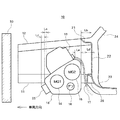
図1はモータケース上に載置されている電力制御装置を内蔵するパワーコントロールユニットケース13の配置構造を示し、図2は、電力制御装置を搭載した車両の前方半分の構造を示している。図1のモータケース18は、トランスアクスルとも呼ばれ、モータケース18は、発電用モータ14であるモータジェネレータ(MG1)と、走行用電動モータであるモータジェネレータ(MG2)と、デファレンシャルギア16と、その他の補機であるオイルポンプ25等を有している。また、電力制御装置は、パワーモジュール、リアクトル、コンデンサ等を含み、バッテリから伸びるパワーケーブルが接続されたPCUケース13の内部に電力制御装置が格納されている。
FIG. 1 shows an arrangement structure of a power
最初に、図2を用いて車両前方のモータルーム10について概説する。モータルーム10は、車室20とモータルーム10とを隔てる隔壁であるダッシュパネル22と、車両の骨格となるサイドメンバ11と、サイドメンバ11に固定されたモータケース18と、フェンダエプロン32を形成するサイドメンバ11の上部に配置されたエプロンアッパーメンバ12と、サイドメンバ11とエプロンアッパーメンバ12とに接続され、車輪31を支えるスプリングが取り付けられるスプリングサポート27と、を有している。また、ダッシュパネル22はカウル21、トーボード23及びダッシュクロスメンバ26を有し、フロントピラー24はエプロンアッパーメンバ12とダッシュパネル22とに接続されている。
First, the
モータルーム10は、エンジンに接続されたモータケース18と、モータケース18の上に配置されたPCUケース13とを有している。なお、これらの構成は、車両の構成部品の一部であり、その他に電動圧縮機、電動パワーステアリング装置、電動ブレーキ装置等のさまざまな機器が取り付けられている。
The
次に、図1を用いてモータルーム10に配置されたモータケース18及びPCケース13について詳説する。なお、重複する車両の構造に関する説明は割愛する。
Next, the
モータケース18は発電用モータ14(MG1)と走行用電動モータ15(MG2)とを有し、モータケース18の上面の車両後方側にPCUケース13が配置されている。本実施形態の一つにおけるモータケース18は、MG1とMG2との内径差を利用して前傾した傾斜面とを有し、この傾斜面にPCUケース13が配置されている。PCUケース13はモータケース18の傾斜により車両前後方向における見かけ上の長さを低減することが可能である。PCUケース13の先端部はモータケース18の先端部から車両後方にずらして配置され、モータケース18の先端からPCUケース13の先端までの距離Laが設定されている。また、PCUケース13の後端からダッシュパネル22までの距離Lbが設定されていることで、衝突によるモータケース18の移動を許容することが可能である。さらに、PCUケース13の後端(パワーケーブルコネクタ端)はPCUケース13の後端から車両前方に奥まった場所に位置し、PCUケース13の後端から距離Leが設定されている。
The
本発明において特徴的な事項は、例えば、衝突の程度を軽衝突と重衝突に分けた場合において、重衝突でもPCUケース13への損傷を抑制するため、距離Laを設定することでモータケース18を積極的に利用するものである。ここで、軽衝突とは、衝突バリア等によって車両前部が凹む程度でエンジンやモータケースが車両後方に移動しない衝突状態を意味し、重衝突とは、衝突バリア等によって車両前部が損傷を受けると共にエンジンやモータケース18が車両後方に移動する衝突状態を意味する。軽衝突では、サイドメンバ11とエプロンアッパーメンバ12とが変形してモータケース18の先端より距離Lcだけ突出しているオイルポンプ25が破損することにより衝突荷重を吸収することで、PCUケース13及びPCUケース13後部の機器に影響が及ばないようにしている。
A characteristic matter in the present invention is that, for example, when the degree of collision is divided into light collision and heavy collision, the
重衝突では、軽衝突と同じようにサイドメンバ11とエプロンアッパーメンバ12とが変形してオイルポンプ25が破損し、さらに、モータケース18が衝突荷重を受け、モータケース18が車両後方へ移動する場合において、モータケース18後端からダッシュパネル22までの距離Lbまで移動してもPCUケース13は距離Laによって影響が抑制され、同様に車室内に与える影響も抑制することがでる。さらに、モータケース18後端がダッシュパネル22まで移動する間にダッシュクロスメンバ26の幅である距離Ldにより、衝突荷重が吸収されることになる。また、PCUケース13の後端からダッシュパネル22までの距離Lbが設定されていることで、衝突によるモータケース18の移動を許容することが可能である。さらに、PCUケース13に接続されているコネクタからモータケース18後端までの距離Leが設定されることで、PCUケース13及びパワーケーブル17に与える影響は抑制されることになる。このようなことから、距離La〜Leは軽衝突及び重衝突共にPCUケースに影響を及ぼさない距離が各種試験及びシミュレーションにて設定されている。
In the heavy collision, the
図3は図2に示した車両の上面図を示し、図4は電力制御装置を内蔵するPCUケース13と隔壁(ダッシュパネル22)との干渉を抑制する構造を示している。最初に図3を用いて軽衝突における変形について述べる。軽衝突ではモータルーム10におけるサイドメンバ11とエプロンアッパーメンバ12の一部が衝突バリア等により変形してエンジン19の前面側に設けられたオイルポンプ25が破損する程度であるため、PCUケース13は損傷を受けることが無い。次に、重衝突の場合は、サイドメンバ11とエプロンアッパーメンバ12とオイルポンプ25はもとより、スプリングサポート27が潰れてエンジン19及びモータケース18が車両後方に移動することになり、エンジン19やモータケース18等が車両のカウル21,ダッシュクロスメンバ26、ダッシュパネル22及びトーボード23に干渉することになる。
3 shows a top view of the vehicle shown in FIG. 2, and FIG. 4 shows a structure for suppressing interference between the
図4のダッシュクロスメンバ26は幅Ldを有し、エンジン19が距離Lbだけ移動して車室20に干渉する際に潰れることによりカウル21、ダッシュパネル22及びトーボード23への影響を抑制する。さらに、ダッシュクロスメンバ26は車両中央部に配置されていることからダッシュクロスメンバ26が潰れた場合でもパワーケーブル17を収容する空間を確保する。このような構成にすることでPCUケース13から伸びるパワーケーブル17への影響を抑制することができる。
The
図5は図1における車両と障害物(衝突バリア30)との衝突による変形を示している。図5の衝突バリア30がモータルーム10に侵入すると、サイドメンバ11とエプロンアッパーメンバ12とオイルポンプ25とモータケース13の先端部とが潰れることで距離La’となり、衝突荷重がモータケース18に加わることでモータケース18が車両後方へ移動する。モータケース18の移動に伴い、スプリングサポートとダッシュクロスメンバ26が潰れることでモータケース18後端とダッシュパネル22までの距離がLb’となるものの、パワーケーブル17への影響は抑制される。また、PCUケースに接続されているパワーケーブルのコネクタ部分も十分な距離Leが確保されている。
FIG. 5 shows a deformation caused by the collision between the vehicle and the obstacle (collision barrier 30) in FIG. When the
以上、上述したように、本実施形態に係るPCUケース13の搭載構造を用いることにより、重衝突においても、サイドメンバの強度を増やすだけではなく、モータケース、フロアアンダーメンバ、トーボード及びフロントピラー等の強度も有効に利用して効率良くエネルギーを受け止めることが可能となる。このようなことから、衝突における衝突バリア30との干渉をモータケース18により食い止め、PCUの破損と感電に対する安全確保が可能となる。
As described above, by using the mounting structure of the
なお、本実施形態では、PCUケースを車両前方へ傾斜させて搭載したが、これは実施形態の1つであり、水平置きや車両後方へ傾斜させて搭載する等の配置でも良い。また、説明の都合のために電動圧縮機等の補機類を省略したが、PCUケース先端及び後端からの距離La〜Leは補機類を含めた値に設定することにより対応することが可能であることはいうまでもない。 In the present embodiment, the PCU case is mounted while being inclined toward the front of the vehicle. However, this is one of the embodiments, and it may be arranged such that the PCU case is mounted horizontally or inclined toward the rear of the vehicle. Moreover, although auxiliary machines, such as an electric compressor, were abbreviate | omitted for convenience of explanation, distance La-Le from a PCU case front-end | tip and a rear end can respond by setting to the value including auxiliary machines. It goes without saying that it is possible.
10 モータルーム、11 サイドメンバ、12 エプロンアッパーメンバ、13 PCUケース、14 発電用モータ、15 走行用電動モータ、16 デファレンシャルギア、17 パワーケーブル、18 モータケース、19 エンジン、20 車室、21 コンデンサ、21 カウル、22 ダッシュパネル、23 トーボード、24 フロントピラー、25 オイルポンプ、26 ダッシュクロスメンバ、27 スプリングサポート、30 衝突バリア、31 車輪、32 フェンダエプロン、110 ハイブリッド自動車、112 モータルーム、114 エンジン、115 モータジェネレータ、116 走行用電動モータ、117 パワーコントロールユニット、118 PCUケース、119 インバータ、120 バッテリ電圧昇圧回路、122 取付座、125 電動圧縮機、126 コンデンサ、127 レシーバ、128 クーリングユニット。
DESCRIPTION OF
Claims (7)
電力制御装置は走行用電動モータを収容するモータケースの上部、かつ、車両後方寄りに配置され、
モータルームと車室とを仕切る隔壁から電力制御装置の後方端までの距離が、モータケース後方端から隔壁までの距離よりも長くなるように電力制御装置をモータケース上に配置したことを特徴とする電力制御装置の搭載構造。 In the mounting structure of the power control device for mounting the power control device that receives the power supply from the battery and controls the electric motor for traveling in the motor room of the vehicle,
The power control device is disposed at the top of the motor case that houses the electric motor for traveling, and closer to the rear of the vehicle,
The power control device is arranged on the motor case so that the distance from the partition that partitions the motor room and the vehicle compartment to the rear end of the power control device is longer than the distance from the rear end of the motor case to the partition. Mounting structure of power control device.
電力制御装置は、車両前方からの衝突荷重を避けるため、モータケースの前方端から予め決められた距離だけ後方に配置することを特徴とする電力制御装置の搭載構造。 In the mounting structure of the power control device according to claim 1,
A structure for mounting a power control device, wherein the power control device is arranged rearward by a predetermined distance from the front end of the motor case in order to avoid a collision load from the front of the vehicle.
車両前方からの衝突荷重を受けることによりモータルーム前方の構造体が変形すると共に、モータケースが隔壁に接触するまで車両後方に移動する場合であっても、隔壁から電力制御装置の後方端までの距離は、電力制御装置後部と隔壁上部との接触を防止する距離であることを特徴とする電力制御装置の搭載構造。 In the mounting structure of the power control device according to claim 1 or 2,
The structure in front of the motor room is deformed by receiving a collision load from the front of the vehicle, and even if the motor case moves to the rear of the vehicle until it contacts the partition, the partition from the partition to the rear end of the power control device The power control device mounting structure, wherein the distance is a distance that prevents contact between the rear portion of the power control device and the upper portion of the partition wall.
電力制御装置における車両前後方向の幅は、モータケースにおける車両前後方向の幅よりも狭く設定したことを特徴とする電力制御装置の搭載方法。 In the mounting structure of the power control device according to any one of claims 1 to 3,
A method for mounting a power control device, wherein a width in a vehicle front-rear direction in the power control device is set narrower than a width in a vehicle front-rear direction in a motor case.
モータケースは車両前方に傾斜した上面を有し、その傾斜した上面に電力制御装置を搭載可能であることを特徴とする電力制御装置の搭載構造。 In the mounting structure of the power control device according to claim 4,
The motor case has an upper surface inclined toward the front of the vehicle, and the power control device can be mounted on the inclined upper surface.
電力制御装置における車両前後方向の幅を見かけ上短くするため、電力制御装置を傾けてモータケース上に搭載したことを特徴とする電力制御装置の搭載方法。 In the mounting structure of the power control device according to claim 4,
A mounting method for a power control device, characterized in that the power control device is tilted and mounted on a motor case in order to make the width of the power control device in the longitudinal direction of the vehicle apparently shorter.
隔壁から電力制御装置の後方端までの距離は、電力制御装置後部と隔壁上部と接触した場合であっても電力制御装置からバッテリへ伸びるケーブルの太さに相当するスペースを確保する距離であることを特徴とする電力制御装置の搭載構造。 In the mounting structure of the power control device according to claim 4,
The distance from the bulkhead to the rear end of the power control device is a distance that secures a space corresponding to the thickness of the cable extending from the power control device to the battery even when the rear portion of the power control device and the top of the bulkhead are in contact. The mounting structure of the power control device characterized by this.
Priority Applications (1)
| Application Number | Priority Date | Filing Date | Title |
|---|---|---|---|
| JP2011006265A JP5602646B2 (en) | 2011-01-14 | 2011-01-14 | Mounting structure of power control device |
Applications Claiming Priority (1)
| Application Number | Priority Date | Filing Date | Title |
|---|---|---|---|
| JP2011006265A JP5602646B2 (en) | 2011-01-14 | 2011-01-14 | Mounting structure of power control device |
Publications (2)
| Publication Number | Publication Date |
|---|---|
| JP2012144227A true JP2012144227A (en) | 2012-08-02 |
| JP5602646B2 JP5602646B2 (en) | 2014-10-08 |
Family
ID=46788256
Family Applications (1)
| Application Number | Title | Priority Date | Filing Date |
|---|---|---|---|
| JP2011006265A Expired - Fee Related JP5602646B2 (en) | 2011-01-14 | 2011-01-14 | Mounting structure of power control device |
Country Status (1)
| Country | Link |
|---|---|
| JP (1) | JP5602646B2 (en) |
Cited By (17)
| Publication number | Priority date | Publication date | Assignee | Title |
|---|---|---|---|---|
| US9266565B2 (en) | 2011-05-20 | 2016-02-23 | Toyota Jidosha Kabushiki Kaisha | Vehicular instrument mounting structure |
| US9469201B2 (en) | 2011-02-03 | 2016-10-18 | Toyota Jidosha Kabushiki Kaisha | Vehicle equipment mounting structure |
| JP2017185913A (en) * | 2016-04-06 | 2017-10-12 | トヨタ自動車株式会社 | Car equipped with a motor for traveling |
| JP2017222203A (en) * | 2016-06-13 | 2017-12-21 | トヨタ自動車株式会社 | On-vehicle structure of power conversion device |
| JP2018083510A (en) * | 2016-11-22 | 2018-05-31 | トヨタ自動車株式会社 | In-vehicle structure of inverter |
| KR20190007460A (en) | 2016-05-25 | 2019-01-22 | 닛산 지도우샤 가부시키가이샤 | Mounting structure of power conversion device |
| JP2019022284A (en) * | 2017-07-13 | 2019-02-07 | 本田技研工業株式会社 | Vehicle and drive circuit unit |
| JP2019025999A (en) * | 2017-07-27 | 2019-02-21 | スズキ株式会社 | Motor room internal structure of electric vehicle |
| JP2020026219A (en) * | 2018-08-10 | 2020-02-20 | トヨタ自動車株式会社 | Vehicle front structure |
| CN110861711A (en) * | 2018-08-07 | 2020-03-06 | 丰田自动车株式会社 | Vehicle front structure |
| JP2020142644A (en) * | 2019-03-06 | 2020-09-10 | 本田技研工業株式会社 | vehicle |
| JP2020158086A (en) * | 2019-03-28 | 2020-10-01 | ダイハツ工業株式会社 | Automobile |
| CN112172491A (en) * | 2019-07-02 | 2021-01-05 | 本田技研工业株式会社 | Drive unit and vehicle |
| JP2022160951A (en) * | 2021-04-07 | 2022-10-20 | 株式会社Subaru | Power control unit mounting structure for vehicle |
| US11590835B2 (en) * | 2020-01-17 | 2023-02-28 | Toyota Jidosha Kabushiki Kaisha | Electric powered vehicle |
| JP2023122971A (en) * | 2022-02-24 | 2023-09-05 | マツダ株式会社 | Vehicle body front structure |
| JP2023184359A (en) * | 2022-06-17 | 2023-12-28 | 本田技研工業株式会社 | Vehicle high voltage equipment mounting structure |
Citations (4)
| Publication number | Priority date | Publication date | Assignee | Title |
|---|---|---|---|---|
| JPH089592A (en) * | 1994-06-21 | 1996-01-12 | Nippondenso Co Ltd | Electric motor |
| JP2007022529A (en) * | 1998-11-16 | 2007-02-01 | Aisin Aw Co Ltd | Drive device |
| JP2011063147A (en) * | 2009-09-18 | 2011-03-31 | Suzuki Motor Corp | Wiring structure of high voltage cable for vehicle |
| WO2012063399A1 (en) * | 2010-11-12 | 2012-05-18 | 本田技研工業株式会社 | Cable arrangement structure for vehicle |
-
2011
- 2011-01-14 JP JP2011006265A patent/JP5602646B2/en not_active Expired - Fee Related
Patent Citations (4)
| Publication number | Priority date | Publication date | Assignee | Title |
|---|---|---|---|---|
| JPH089592A (en) * | 1994-06-21 | 1996-01-12 | Nippondenso Co Ltd | Electric motor |
| JP2007022529A (en) * | 1998-11-16 | 2007-02-01 | Aisin Aw Co Ltd | Drive device |
| JP2011063147A (en) * | 2009-09-18 | 2011-03-31 | Suzuki Motor Corp | Wiring structure of high voltage cable for vehicle |
| WO2012063399A1 (en) * | 2010-11-12 | 2012-05-18 | 本田技研工業株式会社 | Cable arrangement structure for vehicle |
Cited By (30)
| Publication number | Priority date | Publication date | Assignee | Title |
|---|---|---|---|---|
| US9469201B2 (en) | 2011-02-03 | 2016-10-18 | Toyota Jidosha Kabushiki Kaisha | Vehicle equipment mounting structure |
| US9266565B2 (en) | 2011-05-20 | 2016-02-23 | Toyota Jidosha Kabushiki Kaisha | Vehicular instrument mounting structure |
| US10232883B2 (en) | 2016-04-06 | 2019-03-19 | Toyota Jidosha Kabushiki Kaisha | Vehicle equipped with traveling motor |
| JP2017185913A (en) * | 2016-04-06 | 2017-10-12 | トヨタ自動車株式会社 | Car equipped with a motor for traveling |
| US10894471B2 (en) | 2016-05-25 | 2021-01-19 | Nissan Motor Co., Ltd. | Mounting structure for power conversion device |
| KR20190007460A (en) | 2016-05-25 | 2019-01-22 | 닛산 지도우샤 가부시키가이샤 | Mounting structure of power conversion device |
| EP3466733A4 (en) * | 2016-05-25 | 2019-04-10 | Nissan Motor Co., Ltd. | STRUCTURE FOR MOUNTING AN ENERGY CONVERSION DEVICE |
| JP2017222203A (en) * | 2016-06-13 | 2017-12-21 | トヨタ自動車株式会社 | On-vehicle structure of power conversion device |
| JP2018083510A (en) * | 2016-11-22 | 2018-05-31 | トヨタ自動車株式会社 | In-vehicle structure of inverter |
| JP2019022284A (en) * | 2017-07-13 | 2019-02-07 | 本田技研工業株式会社 | Vehicle and drive circuit unit |
| US10457133B2 (en) | 2017-07-13 | 2019-10-29 | Honda Motor Co., Ltd. | Vehicle and drive circuit unit |
| JP2019025999A (en) * | 2017-07-27 | 2019-02-21 | スズキ株式会社 | Motor room internal structure of electric vehicle |
| CN110861711A (en) * | 2018-08-07 | 2020-03-06 | 丰田自动车株式会社 | Vehicle front structure |
| CN110861711B (en) * | 2018-08-07 | 2022-01-04 | 丰田自动车株式会社 | Vehicle front structure |
| JP7196455B2 (en) | 2018-08-10 | 2022-12-27 | トヨタ自動車株式会社 | vehicle front structure |
| JP2020026219A (en) * | 2018-08-10 | 2020-02-20 | トヨタ自動車株式会社 | Vehicle front structure |
| JP2020142644A (en) * | 2019-03-06 | 2020-09-10 | 本田技研工業株式会社 | vehicle |
| CN111660782B (en) * | 2019-03-06 | 2023-06-23 | 本田技研工业株式会社 | vehicle |
| US11374460B2 (en) | 2019-03-06 | 2022-06-28 | Honda Motor Co., Ltd. | Vehicle |
| CN111660782A (en) * | 2019-03-06 | 2020-09-15 | 本田技研工业株式会社 | Vehicle with a steering wheel |
| JP2020158086A (en) * | 2019-03-28 | 2020-10-01 | ダイハツ工業株式会社 | Automobile |
| CN112172491A (en) * | 2019-07-02 | 2021-01-05 | 本田技研工业株式会社 | Drive unit and vehicle |
| CN112172491B (en) * | 2019-07-02 | 2023-06-20 | 本田技研工业株式会社 | Drive unit and vehicle |
| US11590835B2 (en) * | 2020-01-17 | 2023-02-28 | Toyota Jidosha Kabushiki Kaisha | Electric powered vehicle |
| JP2022160951A (en) * | 2021-04-07 | 2022-10-20 | 株式会社Subaru | Power control unit mounting structure for vehicle |
| JP7689007B2 (en) | 2021-04-07 | 2025-06-05 | 株式会社Subaru | Vehicle power control unit mounting structure |
| JP2023122971A (en) * | 2022-02-24 | 2023-09-05 | マツダ株式会社 | Vehicle body front structure |
| JP7700701B2 (en) | 2022-02-24 | 2025-07-01 | マツダ株式会社 | Electric vehicles |
| JP2023184359A (en) * | 2022-06-17 | 2023-12-28 | 本田技研工業株式会社 | Vehicle high voltage equipment mounting structure |
| JP7483793B2 (en) | 2022-06-17 | 2024-05-15 | 本田技研工業株式会社 | High voltage device mounting structure for vehicle |
Also Published As
| Publication number | Publication date |
|---|---|
| JP5602646B2 (en) | 2014-10-08 |
Similar Documents
| Publication | Publication Date | Title |
|---|---|---|
| JP5602646B2 (en) | Mounting structure of power control device | |
| JP5270702B2 (en) | Vehicle equipment mounting structure | |
| CN103338954B (en) | Vehicle Equipment Installation Structure | |
| US10029552B2 (en) | Rear-drive electric vehicle | |
| JP5757283B2 (en) | In-vehicle structure of electronic equipment | |
| CN104284791B (en) | Electronlmobil | |
| US10232883B2 (en) | Vehicle equipped with traveling motor | |
| JP5532877B2 (en) | Vehicle battery arrangement structure | |
| JP5446537B2 (en) | Electric vehicle mounting structure | |
| US11420507B2 (en) | Power train support structure for vehicle | |
| JP5776622B2 (en) | Electric car | |
| JP2020044911A (en) | Vehicle front structure | |
| CN114072300A (en) | Mounting structure of electronic equipment module on vehicle | |
| JP2012121375A (en) | Battery arrangement structure of vehicle | |
| JP2019073237A (en) | Electric vehicle | |
| JP2018118591A (en) | Vehicle structure | |
| JP6597512B2 (en) | In-vehicle structure of power control unit | |
| JP6873572B2 (en) | Protective structure of wiring parts | |
| JP2023107098A (en) | Protective structure of in-vehicle equipment | |
| JP2013193652A (en) | Electric vehicle | |
| JP2024017329A (en) | Transaxle case mounting structure | |
| JP2026029230A (en) | Electric vehicle front structure | |
| JP2017065493A (en) | Collision load relaxation structure | |
| JP2011116242A (en) | Battery arrangement structure of vehicle | |
| WO2014054721A1 (en) | Attachment member for vehicle device |
Legal Events
| Date | Code | Title | Description |
|---|---|---|---|
| A621 | Written request for application examination |
Free format text: JAPANESE INTERMEDIATE CODE: A621 Effective date: 20130328 |
|
| A977 | Report on retrieval |
Free format text: JAPANESE INTERMEDIATE CODE: A971007 Effective date: 20140205 |
|
| A131 | Notification of reasons for refusal |
Free format text: JAPANESE INTERMEDIATE CODE: A131 Effective date: 20140218 |
|
| A521 | Request for written amendment filed |
Free format text: JAPANESE INTERMEDIATE CODE: A523 Effective date: 20140407 |
|
| TRDD | Decision of grant or rejection written | ||
| A01 | Written decision to grant a patent or to grant a registration (utility model) |
Free format text: JAPANESE INTERMEDIATE CODE: A01 Effective date: 20140729 |
|
| A61 | First payment of annual fees (during grant procedure) |
Free format text: JAPANESE INTERMEDIATE CODE: A61 Effective date: 20140820 |
|
| R151 | Written notification of patent or utility model registration |
Ref document number: 5602646 Country of ref document: JP Free format text: JAPANESE INTERMEDIATE CODE: R151 |
|
| R250 | Receipt of annual fees |
Free format text: JAPANESE INTERMEDIATE CODE: R250 |
|
| R250 | Receipt of annual fees |
Free format text: JAPANESE INTERMEDIATE CODE: R250 |
|
| R250 | Receipt of annual fees |
Free format text: JAPANESE INTERMEDIATE CODE: R250 |
|
| R250 | Receipt of annual fees |
Free format text: JAPANESE INTERMEDIATE CODE: R250 |
|
| R250 | Receipt of annual fees |
Free format text: JAPANESE INTERMEDIATE CODE: R250 |
|
| R250 | Receipt of annual fees |
Free format text: JAPANESE INTERMEDIATE CODE: R250 |
|
| R250 | Receipt of annual fees |
Free format text: JAPANESE INTERMEDIATE CODE: R250 |
|
| LAPS | Cancellation because of no payment of annual fees |