JP2012144207A - Carriage with folding fence - Google Patents
Carriage with folding fence Download PDFInfo
- Publication number
- JP2012144207A JP2012144207A JP2011005742A JP2011005742A JP2012144207A JP 2012144207 A JP2012144207 A JP 2012144207A JP 2011005742 A JP2011005742 A JP 2011005742A JP 2011005742 A JP2011005742 A JP 2011005742A JP 2012144207 A JP2012144207 A JP 2012144207A
- Authority
- JP
- Japan
- Prior art keywords
- fence
- piece
- key
- base plate
- protrusion
- Prior art date
- Legal status (The legal status is an assumption and is not a legal conclusion. Google has not performed a legal analysis and makes no representation as to the accuracy of the status listed.)
- Granted
Links
- 230000002093 peripheral effect Effects 0.000 claims description 2
- 238000004080 punching Methods 0.000 claims description 2
- 230000004048 modification Effects 0.000 description 2
- 238000012986 modification Methods 0.000 description 2
- 238000009434 installation Methods 0.000 description 1
- 230000000149 penetrating effect Effects 0.000 description 1
Images

Landscapes
- Handcart (AREA)
Abstract
Description
この発明は、台車上面全周縁に柵を設け、、台車が移動する際の振動で、台車に積載した運搬物が落下するのを防止し、台車不使用時には、柵を台車上に横倒折りたたみ収納が可能な、折りたたみ柵付台車に関するものである。 This invention is provided with a fence on the entire periphery of the upper surface of the carriage, and prevents the cargo loaded on the carriage from falling due to vibrations when the carriage moves. When the carriage is not used, the fence is folded over on the carriage. The present invention relates to a cart with a folding fence that can be stored.
従来このような台車は開発されている。
そこで、この発明はこのような従来技術を考慮してなされたもので、
配送業者が手押し台車と小型荷物を貨物自動車に積載し、到着地で小形荷物を複数積み上げて手押し台車に積載して移動する際、移動時の振動で積載物が滑動したり、道路の段差を移動する際複数の積載物が滑落して、荷物崩壊や変形するのを防止でき、台車不使用時には、柵を折りたたんで台車上に収納できる、折りたたみ柵付台車を提供し、上記課題を解決しようとするものである。
Therefore, the present invention has been made in consideration of such prior art,
When a delivery company loads a wheelbarrow and a small baggage onto a lorry, and stacks multiple small packages at the arrival location and loads them on a wheelbarrow, the load may slide due to vibration during movement, Solve the above problems by providing a trolley with a folding fence that can prevent the load from collapsing and deforming when moving, and can be folded and stored on the trolley when the trolley is not in use. It is what.
そこで請求項1の発明は、
方形形状の板形状体の、一対の相対する側を左右とし、他方の相対する側を前後とした台板と、前記台板上面の前後左右周縁近傍内側に多数の柵を可倒可能に立設してなり、それぞれの柵の内側に板状物または網状物を貼り、
Therefore, the invention of claim 1
A square plate-shaped body with a pair of opposing sides as left and right, and the other opposite side as front and back, and a number of fences standing in front of the front and rear, left and right peripheral edges of the top surface of the base plate. And put a plate or net on the inside of each fence,
前記台板の、
上面左側縁略中央に透孔を設け、左柵突片孔とし、または、筒形状物を接続して、左柵筒突片孔とし、
上面右側縁略中央に透孔を設け、右柵突片孔とし、または、筒形状物を接続して、右柵筒突片孔とし、
下面の左側縁と右側縁の前後に車輪を設け、
Of the base plate,
A through-hole is provided at the approximate center of the upper left side edge to make a left fence protrusion piece hole, or a cylindrical shaped object is connected to make a left fence cylinder protrusion piece hole,
A through hole is provided at the approximate center of the right side of the upper surface to form a right fence protrusion piece hole, or by connecting a cylindrical object to form a right fence cylinder protrusion piece hole,
Provide wheels around the left and right edges on the bottom,
後ろの上面又は側面にп形状部材の開放両端を接続してハンドルとし、
前記柵を構成する各柵は、前記台板の前方に前柵、後方に後ろ柵、右方に右柵、左方に左柵を連続して配置し、
前記前柵と後ろ柵それぞれの高さが前記台板の前後幅の略半分よりやや小さく、
Connect the open ends of the п-shaped member to the top or side of the back to make a handle,
Each of the fences constituting the fence is a front fence in front of the base plate, a rear fence in the rear, a right fence on the right, and a left fence on the left.
The height of each of the front fence and the rear fence is slightly smaller than approximately half of the front and rear width of the base plate,
左右幅は前記台板の左右幅よりやや小さい略四辺形形状で、前記前柵の下辺両端に左右方向に突出した突片を設け、前柵外側突片とし、
前記後ろ柵の下辺両端に左右方向に突出した突片を設け、後ろ柵外側突片とし、
The left and right width is a substantially quadrangular shape that is slightly smaller than the left and right width of the base plate, provided with projecting pieces projecting in the left and right directions at both ends of the lower side of the front fence,
Protruding pieces projecting in the left-right direction on both ends of the lower side of the rear fence, and the rear fence outer protrusion,
前記前柵外側突片は、∩形状部材に回転浮動自在に貫通し、前記∩形状部材の開放両端を、前記台板上面に接続して固定して、前記前柵を前記台板に回転自在に固定し、
前記後ろ柵外側突片は、∩形状部材に回転浮動自在に貫通し、
The outer protrusion of the front fence penetrates the bowl-shaped member so as to be rotatable and floatable, and both open ends of the bowl-shaped member are connected and fixed to the upper surface of the base plate, so that the front fence can be freely rotated on the base plate. Fixed to
The rear fence outer projecting piece penetrates the hook-shaped member so as to freely rotate and float,
前記∩形状部材の開放両端を、前記台板上面に接続して固定して、前記後ろ柵を前記台板に回転自在に固定し、
前記前柵上辺右端に後方に突出して上方に向いたカギ形状の突片を設け、前柵右カギ突片とし、
The open ends of the bowl-shaped member are connected and fixed to the top surface of the base plate, and the rear fence is fixed to the base plate so as to be freely rotatable.
Provide a key-shaped protruding piece that protrudes rearward and protrudes upward at the right edge of the upper side of the front fence, and is a front fence right key protruding piece,
前記後ろ柵上辺右端に前方に突出して上方に向いたカギ形状の突片を設け、後ろ柵右カギ突片とし、
前記前柵の左辺略中央に左方向に突出して、上方に向いたカギ突片を設け、前柵左カギ突片とし、
前記後ろ柵の左辺略中央に左方向に突出して、上方に向いたカギ突片を設け、後ろ柵左カギ突片とし、
Provide a key-shaped protruding piece that protrudes forward and upwards at the right end of the upper side of the rear fence, and is a rear fence right key protruding piece,
Projecting in the left direction approximately at the center of the left side of the front fence, and providing a key protrusion facing upwards, a front fence left key protrusion,
Projecting in the left direction approximately at the center of the left side of the rear fence and providing an upward key protrusion, the rear fence left key protrusion,
前記右柵は高さが前記台板の左右幅よりやや小さく、左右幅は前記台板の前後幅よりやや小さい凹形状で、
下辺略中央に下方に突出して突片を設け右柵下方突片とし、
前記右柵下方突片は前記右側中央孔に貫入抜脱自在で、
The right fence has a concave shape whose height is slightly smaller than the left and right width of the base plate, and the left and right width is slightly smaller than the front and rear width of the base plate,
Protruding downwards at the center of the lower side and providing a protruding piece as a right fence downward protruding piece,
The right fence lower projecting piece can be inserted into and removed from the right central hole.
前記右柵下辺両端に前および後方向に突出して突片を設け右柵外側突片とし、
それぞれの前記右柵外側突片は、∩形状部材に回転浮動自在に貫通し、前記∩形状部材の開放両端を前記台板上面に接続固定して、
Protruding pieces projecting in the front and rear directions at both ends of the lower side of the right fence to provide a right fence outer protruding piece,
Each of the right fence outer projecting pieces penetrates the bowl-shaped member so as to rotate and float, and the open ends of the bowl-shaped member are connected and fixed to the upper surface of the base plate,
前記右柵外側突片を前記台板に回転自在に固定し、
前記右柵を前記台板上面に横倒定置した際、凹部を除く全辺上に上方に突出して枠を設け、右柵突出枠とし、
Fixing the right fence outer protrusion to the base plate rotatably,
When the right fence is placed sideways on the top surface of the base plate, a frame is provided to protrude upward on all sides except the concave portion, and a right fence protruding frame is provided.
前記右柵上辺前方端に内側に突出して、下方に向いたカギ形状の突片を設け、右柵前カギ突片とし、
前記右柵上辺後方端に内側に突出して、下方に向いたカギ形状の突片を設け、右柵後ろカギ突片とし、
前記右柵前カギ突片は、前記前柵右カギ突片と掛合離反自在であり、
Protruding inwardly at the front end of the upper side of the right fence, and providing a key-shaped projecting piece facing downward, and a key projecting piece in front of the right fence,
Protruding inwardly at the rear edge of the upper side of the right fence, and providing a key-shaped projecting piece facing downward, as a right fence rear key projecting piece,
The right fence front key projection piece is free to engage with and separate from the front fence right key projection piece,
前記右柵後ろカギ突片は、前記後ろ柵右カギ突片と掛合離反自在であり、
前記左柵は高さが前記台板の左右幅よりやや小さく、左右幅は前記台板の前後幅よりやや小さく、
半体である下方が四辺形形状枠体の上方に、半円形形状枠を接続し、
The right fence rear key projection piece is free to engage with and separate from the rear fence right key projection piece,
The left fence is slightly smaller than the left and right width of the base plate, the left and right width is slightly smaller than the front and rear width of the base plate,
Connect the semicircular frame to the lower half of the quadrilateral frame,
前記四辺形形状枠体上辺の前端に前方に突出して、下方に向いたカギ突片を接続し左柵カギ突片前とし、当該左柵カギ突片前は、前記前柵左カギ突片と掛合離反自在になっており、
前記四辺形形状枠体上辺の後ろ端に後方に突出して、下方に向いたカギ突片を接続し左柵カギ突片後ろとし、
Projecting forward to the front end of the upper side of the quadrilateral frame body, connecting a downwardly-facing key projection piece to the front of the left fence key projection piece, the front of the left fence key projection piece is the front fence left key projection piece and It is free to engage and disengage,
Projecting backward at the rear end of the upper side of the quadrilateral frame body, connecting the key protrusion facing downward and the left fence key protrusion behind,
当該左柵カギ突片後ろは、前述後ろ柵左カギ突片と掛合離反自在になっており、
当該半円形形状枠の略中央に左方に突出した突片を設け、取っ手とし、
前記左柵の下辺中央に下方に突出して突片を設け、左柵下方突片とし、
The back of the left fence key piece is free to engage and disengage from the rear fence left key piece,
Provide a projecting piece protruding to the left at the approximate center of the semicircular frame,
A projecting piece is provided projecting downward at the center of the lower side of the left fence, and is a left fence lower projecting piece,
当該左柵下方突片は前記左側中央孔に貫入抜脱自在で、
前記左柵下辺両端に前および後方向に突出して突片を設け左柵外側突片とし、
それぞれの前記左柵外側突片は、∩形状部材に回転浮動自在に貫通し、前記∩形状部材の開放両端を前記台板上面に接続固定して、
The left rail lower projecting piece can be freely inserted into and removed from the left central hole,
Protruding pieces projecting in the front and rear directions at both ends of the lower left side of the left fence to form a left fence outer protruding piece,
Each of the left fence outer projecting pieces penetrates the bowl-shaped member so as to rotate and float, and the open both ends of the bowl-shaped member are connected and fixed to the upper surface of the base plate,
前記左柵外側突片を前記台板に回転自在に固定し、
前記左柵下方突片を前記左側中央孔に貫入して立設し固定し、前記右柵下方突片を前記右側中央孔に貫入して立設し固定し、
全面前柵と前記後ろ柵を立設し、
The left rail outer protrusion is fixed to the base plate rotatably,
The left fence lower protruding piece penetrates into the left central hole and stands and is fixed, and the right fence lower protruding piece penetrates into the right center hole and is fixed and fixed,
Establish the front fence and the rear fence,
前記前柵右カギ突片および前記後ろ柵右カギ突片に前記右柵上辺両端のそれぞれの前記右柵カギ突片を掛合して、当該前柵と当該後ろ柵を固定し、左柵カギ突片前と前柵左カギ突片を掛合し、左柵カギ突片後ろと後ろ柵左カギ突片を掛合して構成する。 The front fence right key protrusion piece and the rear fence right key protrusion piece are engaged with the right fence key protrusion pieces at both ends of the upper side of the right fence, and the front fence and the rear fence are fixed. The front and left fence protrusions are hooked on one side, and the rear and left fence protrusions on the left fence hook are hooked together.
請求項2の発明は、
前記台板には前記車輪と前記ハンドルを設けない。
請求項3の発明は、
前記前柵、前記後ろ柵、前記右柵、または、前記左柵の下辺中央部位に間隙を設けた。
請求項4の発明は、
前記台板上面に接続する前記∩形状部材は、前記台板を凸形状に打ち抜いて構成する。
The invention of claim 2
The wheel and the handle are not provided on the base plate.
The invention of claim 3
A gap was provided at a central part of the lower side of the front fence, the rear fence, the right fence, or the left fence.
The invention of
The hook-shaped member connected to the top surface of the base plate is formed by punching the base plate into a convex shape.
請求項1の発明によれば、完成した状態から、
左柵を引き上げ、左柵下方突片を左柵突片孔から抜脱し、左柵カギ突片前と前柵左カギ突片との掛合を解き、左柵カギ突片後ろと後ろ柵左カギ突片との掛合を解き、左柵を前記台板上に横倒し、
According to the invention of claim 1, from the completed state,
Pull up the left fence, pull out the left fence lower protrusion from the left fence protrusion hole, disengage the front of the left fence lock protrusion and the front fence left lock protrusion, behind the left fence lock protrusion and the rear fence left lock Unhook the projecting piece, lay the left rail on the base plate,
次に、右柵を引き上げ、右柵下方突片を右柵突片孔から抜脱し、右柵前カギ突片と前柵右カギ突片との掛合を解き、右柵後ろカギ突片と後ろ柵右カギ突片の掛合を解き、前柵と後ろ柵を左柵上に横倒重置し、右柵を前柵と前記後ろ柵上に横倒重置すると、 Next, pull up the right fence, pull out the right fence lower protrusion from the right fence protrusion hole, unhook the right fence front lock protrusion and the front fence right lock protrusion, and the right fence rear lock protrusion and rear. Unlocking the fence right key projecting piece, placing the front fence and the rear fence sideways on the left fence, placing the right fence sideways on the front fence and the rear fence,
右柵の凹部の間から取っ手が上方に突出した状態に収納し、
右柵突出枠が右柵上に位置するので、すべての柵を収納した状態でも、右柵突片枠内側に運搬物を積載し、右柵突出枠で積載物の滑落を防止し運搬可能である。
Store the handle protruding upward from between the recesses on the right fence,
Since the right fence protruding frame is located on the right fence, even when all the fences are stored, the load can be loaded inside the right fence protruding piece frame, and the right fence protruding frame can prevent the load from falling and can be carried. is there.
取っ手を引き上げて左柵を起立させると、左柵の半円形形状部位が、前柵と後ろ柵の上辺に摺接して、前柵と後ろ柵が同時に上昇し、
同時に前柵と後ろ柵の上辺が、右柵上辺に摺接して右柵が起立するので、右柵下方突片を右側突片孔に貫入して右柵を立設固定し、
When the handle is lifted and the left fence is raised, the semicircular part of the left fence slides on the upper sides of the front and rear fences, and the front and rear fences rise simultaneously.
At the same time, the upper fence of the front fence and the rear fence are in sliding contact with the upper edge of the right fence, and the right fence stands, so the right fence lower part is inserted into the right protrusion hole, and the right fence is erected and fixed.
右柵前カギ突片と前柵右カギ突片を掛合し前柵を立設固定し、右柵後ろカギ突片と後ろ柵右カギ突片を掛合し後ろ柵を立設固定し、
左柵を引き上げ、左柵下方突片を左側突片孔に貫入し、左柵カギ突片前と前柵左カギ突片を掛合し、
The right fence front key protrusion and the front fence right key protrusion are hooked and the front fence is erected and fixed, the right fence rear key protrusion and the rear fence right key protrusion are hooked, and the rear fence is erected and fixed.
Pull up the left fence, penetrate the left fence lower protrusion into the left protrusion hole, engage the left fence lock piece and the front fence left lock piece,
左柵カギ突片後ろと後ろ柵左カギ突片を掛合して左柵を立設固定しすると、折りたたみ枠付台車となる。
請求項2の発明によれば、前記台板に車輪とハンドルを設けない状態で、既存市販の台車上面に台板を接続することで、既存市販の台車を容易に折りたたみ枠枠付台車に改造できる。
When the left fence is fixed upright by hooking the left fence key protrusion behind and the left fence lock piece, it becomes a cart with a folding frame.
According to the invention of claim 2, an existing commercially available cart can be easily converted to a cart with a folding frame by connecting a base plate to the upper surface of an existing commercially available cart without providing wheels and handles on the base plate. it can.
請求項3の発明によれば、前柵と後ろ柵と右柵と左柵の下辺中央部位に間隙を設けたことで、∩形状部材を台板に接続した後、
前柵と後ろ柵と右柵と左柵のそれぞれの左辺と右辺を中央方向に押縮して、前柵のそれぞれの外側突片と、
According to the invention of claim 3, by providing a gap in the central part of the lower side of the front fence, the rear fence, the right fence and the left fence, after connecting the bowl-shaped member to the base plate,
The left and right sides of each of the front, rear, right, and left fences are compressed in the center direction,
後ろ柵のそれぞれの外側突片と、右柵のそれぞれの外側突片と、左柵のそれぞれの外側突片を、回転浮動自在に∩形状部材に貫通して接続することが可能となり、各∩形状部材に各柵を貫通しながら個々に接続するわずらわしさが解消できる。 It is possible to connect the outer protruding pieces of the rear fence, the outer protruding pieces of the right fence, and the outer protruding pieces of the left fence so as to be able to rotate and float through the hook-shaped member. The troublesome connection to the shape member while penetrating each fence can be eliminated.
請求項4の発明によれば、台板を構成する平板の∩形状部材構成位置に、∩形状部材構成用凸型枠と凹型枠を配置して∩形状部材を圧造し、∩形状部材を構成することで、台板と∩形状部材を一体構成することが可能となる。
According to the invention of
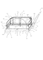
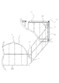
この発明を、図に基づき説明する。
台板1の上左側縁略中央に左柵突片孔2を設け、または、筒形状物を接続して、左柵筒突片孔3とし、
右側縁略中央に右柵突片孔4を設け、または、筒形状物を接続して、右柵筒突片孔5とし、
The present invention will be described with reference to the drawings.
A left fence protruding piece hole 2 is provided at substantially the center of the upper left edge of the base plate 1 or a cylinder-shaped object is connected to form a left fence protruding piece hole 3.
The right fence protruding
台板1下面の左側縁と右側縁の前後に車輪31を設け、
後ろの上面又は側面にп形状部材の開放両端を接続してハンドル32とし、
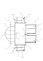
前と後ろの右柵外側突片18を∩形状部材6に回転浮動自在に貫通し、右柵14を回転自在に台板1に固定し、
Wheels 31 are provided before and after the left and right edges of the bottom surface of the base plate 1,
Connect the open ends of the п-shaped member to the top or side of the back to make the handle 32,
The front and rear right fence outer projecting pieces 18 pass through the bowl-shaped member 6 so as to freely rotate and float, and the right fence 14 is rotatably fixed to the base plate 1.
右柵下方突片15を右柵突片孔4に貫入して、右柵14を台板1上右側に立設固定し、
左と右の前柵外側突片24を∩形状部材6に回転浮動自在に貫通し、前柵を回転自在に台板1に固定し、
前柵右カギ突片と右柵前カギ突片16を掛合し、前柵を立設し、
The right fence lower protrusion 15 is inserted into the right
The left and right front fence outer projecting pieces 24 penetrate the bowl-shaped member 6 so as to be able to rotate and float, and the front fence is rotatably fixed to the base plate 1.
The front fence right key protrusion and the right fence front protrusion 16 are hooked, and the front fence is erected,
左と右の後ろ柵外側突片を∩形状部材6に回転浮動自在に貫通し、後ろ柵26を回転自在に台板1に固定し、
後ろ柵右カギ突片28と右柵後ろカギ突片17を掛合し、後ろ柵26を立設し、
The left and right rear fence outer protrusions penetrate the bowl-shaped member 6 so as to be able to rotate and float, and the rear fence 26 is rotatably fixed to the base plate 1.
The rear fence right key protrusion 28 and the right fence rear key protrusion 17 are engaged, and the rear fence 26 is erected,
前と後ろの左柵外側突片12を∩形状部材6に回転浮動自在に貫通し、左柵7を回転自在に台板1に固定し、
左柵下方突片9を左柵突片孔2に貫通して、
The front and rear left fence outer protrusions 12 are pierced through the bowl-shaped member 6 so as to be able to rotate and float, and the left fence 7 is rotatably fixed to the base plate 1.
Through the left fence lower protrusion 9 through the left fence protrusion 2,
左柵7を台板1上左側に立設固定し、
左柵カギ突片前10と前柵左カギ突片22を掛合し、
左柵カギ突片後ろ11と後ろ柵左カギ突片27を掛合すると、折りたたみ柵付台車が出来上がる。
Fix the left fence 7 upright on the left side of the base plate 1,
Multiply the left fence key piece 10 and the front fence left key piece 22,
When the rear fence key protrusion 11 and the rear fence lock 27 are engaged, a cart with a folding fence is completed.
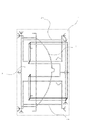
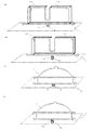
左柵7を引き上げ、左柵下方突片9を左柵突片孔2から抜脱し、左柵カギ突片前10と前柵左カギ突片22との掛合を解き、左柵カギ突片後ろと11後ろ柵左カギ突片27との掛合を解き、左柵7を前記台板1上に横倒し、 Pull up the left fence 7, remove the left fence lower protrusion 9 from the left fence protrusion hole 2, unhook the left fence key protrusion 10 and the front fence left lock protrusion 22, and behind the left fence lock protrusion 11 and 11 and the rear fence left key protrusion 27 is released, the left fence 7 is laid down on the base plate 1,
次に、右柵14を引き上げ、右柵下方突片15を右柵突片孔4から抜脱し、右柵前カギ突片16と前柵右カギ突片23との掛合を解き、右柵後ろカギ突片17と後ろ柵右カギ突片28の掛合を解き、前柵21と後ろ柵26を左柵7上に横倒重置し、
Next, the right fence 14 is lifted, the right fence lower protrusion 15 is removed from the right
右柵14を前柵21と後ろ柵26上に横倒重置すると、右柵突出枠19が右柵14上に位置し、右柵14の凹部の間から取っ手8が上方に突出した状態に収納できる。
収納状態から、取っ手8を引き上げて左柵7を起立させると、
When the right fence 14 is placed sideways on the front fence 21 and the rear fence 26, the right fence protruding frame 19 is positioned on the right fence 14, and the handle 8 protrudes upward from between the recesses of the right fence 14. Can be stored.
From the stowed state, pull up the handle 8 and erect the left rail 7.
左柵7の半円形形状部位が、前柵21と後ろ柵26の上辺に摺接して、前柵21と後ろ柵26が同時に上昇し、
同時に前柵21と後ろ柵26の上辺が、右柵14上辺に摺接して右柵14が起立するので、
The semicircular portion of the left fence 7 is in sliding contact with the upper sides of the front fence 21 and the rear fence 26, and the front fence 21 and the rear fence 26 are simultaneously raised.
At the same time, the upper side of the front fence 21 and the rear fence 26 is in sliding contact with the upper side of the right fence 14 so that the right fence 14 stands.
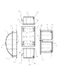
右柵下方突片15を右柵突片孔4に貫入して右柵14を立設固定し、
右柵前カギ突片16と前柵右カギ突片23を掛合し前柵21を立設固定し、右柵後ろカギ突片1728と後ろ柵右カギ突片を掛合し後ろ柵26を立設固定し、
The right fence lower protrusion 15 is inserted into the right
The right fence front key protrusion 16 and the front fence right key protrusion 23 are hooked and the front fence 21 is fixed upright, and the right fence rear key protrusion 1728 and the rear fence right key protrusion are hooked and the rear fence 26 is set up. Fixed,
左柵7を引き上げ、左柵下方突片9を左柵突片孔2に貫入し、左柵カギ突片前10と前柵左カギ突片22を掛合し、左柵カギ突片後ろ11と後ろ柵左カギ突片27を掛合して左柵7を立設固定すると、折りたたみ枠付台車となる。 Pull up the left fence 7, penetrate the left fence lower protrusion 9 into the left fence protrusion hole 2, engage the left fence lock protrusion 10 and the front fence left lock protrusion 22, and the left fence lock protrusion 11 When the rear fence left key protruding piece 27 is engaged and the left fence 7 is fixed upright, it becomes a cart with a folding frame.
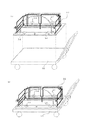
図8に示すように、本体32を市販台車35に鋲34で固定することで、市販台車35を容易に折りたたみ枠付台車に改造できる。
前柵21の下辺中央部位に前柵間隙25を、後ろ柵26の下辺中央部位に後ろ柵間隙30を、
As shown in FIG. 8, the commercial cart 35 can be easily remodeled into a cart with a folding frame by fixing the main body 32 to the commercial cart 35 with a flange 34.
The front fence gap 25 is provided at the lower central part of the front fence 21, and the rear fence gap 30 is provided at the lower central part of the rear fence 26.
右柵14の下辺中央部位に右柵間隙20を、または、左柵7の下辺中央部位に左柵間隙13を設け、
台板1に∩形状部材6を接続した後、各柵の左辺と右辺を中央方向に押縮して、各柵の外側突片を∩形状部材6に回転浮動自在に接続することが可能となる。
A right fence gap 20 is provided at the lower middle part of the right fence 14, or a left fence gap 13 is provided at the lower middle part of the left fence 7,
After connecting the bowl-shaped member 6 to the base plate 1, the left and right sides of each fence can be compressed in the center direction, and the outer protrusions of each fence can be connected to the bowl-shaped member 6 in a freely rotatable manner. Become.
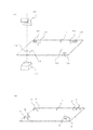
図9に示すように、台板1のそれぞれの∩形状部材構成位置38の上面に凹型36を、相対する下面に凸型37を置き、凹型36と凸型37で台板1を圧造して∩形状部材6を構成し、順次、それぞれの∩形状部材構成位置38へ凹型36と凸型37を移動し、それぞれの∩形状部材6を構成することが可能である。
As shown in FIG. 9, a concave mold 36 is placed on the upper surface of each bowl-shaped member constituting position 38 of the base plate 1, and a convex mold 37 is placed on the opposite lower surface, and the base plate 1 is pressed by the concave mold 36 and the convex mold 37. It is possible to configure the bowl-shaped member 6 and to sequentially move the concave mold 36 and the convex mold 37 to the respective bowl-shaped member configuration positions 38 to configure the respective bowl-shaped members 6.
1 台板
2 左柵突片孔
3 左柵筒突片孔
4 右柵突片孔
5 右柵筒突片孔
6 ∩形状部材
7 左柵
8 取っ手
9 左柵下方突片
10 左柵カギ突片前
11 左柵カギ突片後ろ
12 左柵外側突片
13 左柵間隙
14 右柵
15 右柵下方突片
16 右柵前カギ突片
17 右柵後ろカギ突片
18 右柵外側突片
19 右柵突出枠
20 右柵間隙
21 前柵
22 前柵左カギ突片
23 前柵右カギ突片
24 前柵外側突片
25 前柵間隙
26 後ろ柵
27 後ろ柵左カギ突片
28 後ろ柵右カギ突片
29 後ろ柵外側突片
30 後ろ柵間隙
31 車輪
32 ハンドル
33 本体
34 鋲
35 市販台車
36 凹型
37 凸型
38 ∩形状部材構成位置
1 Base plate 2 Left fence protrusion piece 3 Left fence
Claims (4)
前記台板の、
上面左側縁略中央に透孔を設け、左柵突片孔とし、または、筒形状物を接続して、左柵筒突片孔とし、
上面右側縁略中央に透孔を設け、右柵突片孔とし、または、筒形状物を接続して、右柵筒突片孔とし、
下面の左側縁と右側縁の前後に車輪を設け、
後ろの上面又は側面にп形状部材の開放両端を接続してハンドルとし、
前記柵を構成する各柵は、前記台板の前方に前柵、後方に後ろ柵、右方に右柵、左方に左柵を連続して配置し、
前記前柵と後ろ柵それぞれの高さが前記台板の前後幅の略半分よりやや小さく、左右幅は前記台板の左右幅よりやや小さい略四辺形形状で、前記前柵の下辺両端に左右方向に突出した突片を設け、前柵外側突片とし、
前記後ろ柵の下辺両端に左右方向に突出した突片を設け、後ろ柵外側突片とし
前記前柵外側突片は、∩形状部材に回転浮動自在に貫通し、前記∩形状部材の開放両端を、前記台板上面に接続して固定して、前記前柵を前記台板に回転自在に固定し、
前記後ろ柵外側突片は、∩形状部材に回転浮動自在に貫通し、前記∩形状部材の開放両端を、前記台板上面に接続して固定して、前記後ろ柵を前記台板に回転自在に固定し、
前記前柵上辺右端に後方に突出して上方に向いたカギ形状の突片を設け、前柵右カギ突片とし、
前記後ろ柵上辺右端に前方に突出して上方に向いたカギ形状の突片を設け、後ろ柵右カギ突片とし、
前記前柵の左辺略中央に左方向に突出して、上方に向いたカギ突片を設け、前柵左カギ突片とし、
前記後ろ柵の左辺略中央に左方向に突出して、上方に向いたカギ突片を設け、後ろ柵左カギ突片とし、
前記右柵は高さが前記台板の左右幅よりやや小さく、左右幅は前記台板の前後幅よりやや小さい凹形状で、
下辺略中央に下方に突出して突片を設け右柵下方突片とし、
前記右柵下方突片は前記右側中央孔に貫入抜脱自在で、
前記右柵下辺両端に前および後方向に突出して突片を設け右柵外側突片とし、
それぞれの前記右柵外側突片は、∩形状部材に回転浮動自在に貫通し、前記∩形状部材の開放両端を前記台板上面に接続固定して、
前記右柵外側突片を前記台板に回転自在に固定し、
前記右柵を前記台板上面に横倒定置した際、凹部を除く全辺上に上方に突出して枠を設け、右柵突出枠とし、
前記右柵上辺前方端に内側に突出して、下方に向いたカギ形状の突片を設け、右柵前カギ突片とし、
前記右柵上辺後方端に内側に突出して、下方に向いたカギ形状の突片を設け、右柵後ろカギ突片とし、
前記右柵前カギ突片は、前記前柵右カギ突片と掛合離反自在であり、
前記右柵後ろカギ突片は、前記後ろ柵右カギ突片と掛合離反自在であり、
前記左柵は高さが前記台板の左右幅よりやや小さく、左右幅は前記台板の前後幅よりやや小さく、
半体である下方が四辺形形状枠体の上方に、半円形形状枠を接続し、
前記四辺形形状枠体上辺の前端に前方に突出して、下方に向いたカギ突片を接続し左柵カギ突片前とし、当該左柵カギ突片前は、前記前柵左カギ突片と掛合離反自在になっており、
前記四辺形形状枠体上辺の後ろ端に後方に突出して、下方に向いたカギ突片を接続し左柵カギ突片後ろとし、
当該左柵カギ突片後ろは、前述後ろ柵左カギ突片と掛合離反自在になっており、
当該半円形形状枠の略中央に左方に突出した突片を設け、取っ手とし、
前記左柵の下辺中央に下方に突出して突片を設け、左柵下方突片とし、
当該左柵下方突片は前記左側中央孔に貫入抜脱自在で、
前記左柵下辺両端に前および後方向に突出して突片を設け左柵外側突片とし、
それぞれの前記左柵外側突片は、∩形状部材に回転浮動自在に貫通し、前記∩形状部材の開放両端を前記台板上面に接続固定して、
前記左柵外側突片を前記台板に回転自在に固定し、
前記左柵下方突片を前記左側中央孔に貫入して立設し固定し、前記右柵下方突片を前記右側中央孔に貫入して立設し固定し、
全面前柵と前記後ろ柵を立設し、前記前柵右カギ突片および前記後ろ柵右カギ突片に前記右柵上辺両端のそれぞれの前記右柵カギ突片を掛合して、当該前柵と当該後ろ柵を固定し、左柵カギ突片前と前柵左カギ突片を掛合し、左柵カギ突片後ろと後ろ柵左カギ突片を掛合して構成する、ことを特徴とする折りたたみ柵付台車。 A square plate-shaped body with a pair of opposing sides as left and right, and the other opposite side as front and back, and a number of fences standing in front of the front and rear, left and right peripheral edges of the top surface of the base plate. And put a plate or net on the inside of each fence,
Of the base plate,
A through-hole is provided at the approximate center of the upper left side edge to make a left fence protrusion piece hole, or a cylindrical shaped object is connected to make a left fence cylinder protrusion piece hole,
A through hole is provided at the approximate center of the right side of the upper surface to form a right fence protrusion piece hole, or by connecting a cylindrical object to form a right fence cylinder protrusion piece hole,
Provide wheels around the left and right edges on the bottom,
Connect the open ends of the п-shaped member to the top or side of the back to make a handle,
Each of the fences constituting the fence is a front fence in front of the base plate, a rear fence in the rear, a right fence on the right, and a left fence on the left.
The height of each of the front fence and the rear fence is slightly smaller than approximately half of the front and rear width of the base plate, and the left and right width is a substantially quadrilateral shape slightly smaller than the left and right width of the base plate. Protruding pieces projecting in the direction are provided as front fence outer protruding pieces,
Protruding pieces projecting in the left-right direction are provided at both ends of the lower side of the rear fence, and the front fence outer protruding pieces penetrate the hook-shaped member so as to be rotatable and floatable, and open ends of the hook-shaped member are provided. , Fixed by connecting to the upper surface of the base plate, the front fence is rotatably fixed to the base plate,
The rear fence outer projecting piece penetrates the bowl-shaped member so as to rotate and float, and the open ends of the bowl-shaped member are connected and fixed to the top surface of the base plate so that the rear fence can be freely rotated on the base plate. Fixed to
Provide a key-shaped protruding piece that protrudes rearward and protrudes upward at the right edge of the upper side of the front fence, and is a front fence right key protruding piece,
Provide a key-shaped protruding piece that protrudes forward and upwards at the right end of the upper side of the rear fence, and is a rear fence right key protruding piece,
Projecting in the left direction approximately at the center of the left side of the front fence, and providing a key protrusion facing upwards, a front fence left key protrusion,
Projecting in the left direction approximately at the center of the left side of the rear fence and providing an upward key protrusion, the rear fence left key protrusion,
The right fence has a concave shape whose height is slightly smaller than the left and right width of the base plate, and the left and right width is slightly smaller than the front and rear width of the base plate,
Protruding downwards at the center of the lower side and providing a protruding piece as a right fence downward protruding piece,
The right fence lower projecting piece can be inserted into and removed from the right central hole.
Protruding pieces projecting in the front and rear directions at both ends of the lower side of the right fence to provide a right fence outer protruding piece,
Each of the right fence outer projecting pieces penetrates the bowl-shaped member so as to rotate and float, and the open ends of the bowl-shaped member are connected and fixed to the upper surface of the base plate,
Fixing the right fence outer protrusion to the base plate rotatably,
When the right fence is placed sideways on the top surface of the base plate, a frame is provided to protrude upward on all sides except the concave portion, and a right fence protruding frame is provided.
Protruding inwardly at the front end of the upper side of the right fence, and providing a key-shaped projecting piece facing downward, and a key projecting piece in front of the right fence,
Protruding inwardly at the rear edge of the upper side of the right fence, and providing a key-shaped projecting piece facing downward, as a right fence rear key projecting piece,
The right fence front key projection piece is free to engage with and separate from the front fence right key projection piece,
The right fence rear key projection piece is free to engage with and separate from the rear fence right key projection piece,
The left fence is slightly smaller than the left and right width of the base plate, the left and right width is slightly smaller than the front and rear width of the base plate,
Connect the semicircular frame to the lower half of the quadrilateral frame,
Projecting forward to the front end of the upper side of the quadrilateral frame body, connecting a downwardly-facing key projection piece to the front of the left fence key projection piece, the front of the left fence key projection piece is the front fence left key projection piece and It is free to engage and disengage,
Projecting backward at the rear end of the upper side of the quadrilateral frame body, connecting the key protrusion facing downward and the left fence key protrusion behind,
The back of the left fence key piece is free to engage and disengage from the rear fence left key piece,
Provide a projecting piece protruding to the left at the approximate center of the semicircular frame,
A projecting piece is provided projecting downward at the center of the lower side of the left fence, and is a left fence lower projecting piece,
The left rail lower projecting piece can be freely inserted into and removed from the left central hole,
Protruding pieces projecting in the front and rear directions at both ends of the lower left side of the left fence to form a left fence outer protruding piece,
Each of the left fence outer projecting pieces penetrates the bowl-shaped member so as to rotate and float, and the open both ends of the bowl-shaped member are connected and fixed to the upper surface of the base plate,
The left rail outer protrusion is fixed to the base plate rotatably,
The left fence lower protruding piece penetrates into the left central hole and stands and is fixed, and the right fence lower protruding piece penetrates into the right center hole and is fixed and fixed,
The front fence and the rear fence are erected, and the front fence right key protrusion piece and the rear fence right key protrusion piece are engaged with the right fence key protrusion pieces on both ends of the right fence, and the front fence The rear fence is fixed, the left fence key piece front and the front fence left key piece are engaged, and the left fence key piece rear and the rear fence left key piece are engaged. A cart with a folding fence.
Priority Applications (1)
| Application Number | Priority Date | Filing Date | Title |
|---|---|---|---|
| JP2011005742A JP5351185B2 (en) | 2011-01-14 | 2011-01-14 | Cart with folding fence |
Applications Claiming Priority (1)
| Application Number | Priority Date | Filing Date | Title |
|---|---|---|---|
| JP2011005742A JP5351185B2 (en) | 2011-01-14 | 2011-01-14 | Cart with folding fence |
Publications (2)
| Publication Number | Publication Date |
|---|---|
| JP2012144207A true JP2012144207A (en) | 2012-08-02 |
| JP5351185B2 JP5351185B2 (en) | 2013-11-27 |
Family
ID=46788240
Family Applications (1)
| Application Number | Title | Priority Date | Filing Date |
|---|---|---|---|
| JP2011005742A Expired - Fee Related JP5351185B2 (en) | 2011-01-14 | 2011-01-14 | Cart with folding fence |
Country Status (1)
| Country | Link |
|---|---|
| JP (1) | JP5351185B2 (en) |
Cited By (2)
| Publication number | Priority date | Publication date | Assignee | Title |
|---|---|---|---|---|
| CN105015595A (en) * | 2015-08-07 | 2015-11-04 | 浙江荣新工贸有限公司 | Combined connecting mechanism for tortoise car supporting plates |
| TWI880755B (en) * | 2024-05-24 | 2025-04-11 | 康得倫事業有限公司 | Cart |
Citations (2)
| Publication number | Priority date | Publication date | Assignee | Title |
|---|---|---|---|---|
| JPH07205818A (en) * | 1994-01-27 | 1995-08-08 | Yamato Denki Kogyo Kk | Traction carriage with frame |
| JPH10250379A (en) * | 1997-03-13 | 1998-09-22 | Honda Motor Co Ltd | Dolly top frame structure |
-
2011
- 2011-01-14 JP JP2011005742A patent/JP5351185B2/en not_active Expired - Fee Related
Patent Citations (2)
| Publication number | Priority date | Publication date | Assignee | Title |
|---|---|---|---|---|
| JPH07205818A (en) * | 1994-01-27 | 1995-08-08 | Yamato Denki Kogyo Kk | Traction carriage with frame |
| JPH10250379A (en) * | 1997-03-13 | 1998-09-22 | Honda Motor Co Ltd | Dolly top frame structure |
Cited By (2)
| Publication number | Priority date | Publication date | Assignee | Title |
|---|---|---|---|---|
| CN105015595A (en) * | 2015-08-07 | 2015-11-04 | 浙江荣新工贸有限公司 | Combined connecting mechanism for tortoise car supporting plates |
| TWI880755B (en) * | 2024-05-24 | 2025-04-11 | 康得倫事業有限公司 | Cart |
Also Published As
| Publication number | Publication date |
|---|---|
| JP5351185B2 (en) | 2013-11-27 |
Similar Documents
| Publication | Publication Date | Title |
|---|---|---|
| US9428205B2 (en) | Security cart | |
| US8091916B2 (en) | Fold flat carrier wagon/cart with stowable walls, wheels and handle, and manufacturing methods | |
| US8267018B2 (en) | Load support | |
| KR200470963Y1 (en) | Folding pallet of the automobile parts lift | |
| KR101648388B1 (en) | Container pallete | |
| US20150097346A1 (en) | Convertible scooter ride-on | |
| CN105849424B (en) | Assembly type block is constructed and latch-release part | |
| JP5351185B2 (en) | Cart with folding fence | |
| KR101243973B1 (en) | Board carrier | |
| JP6375727B2 (en) | Roll product container | |
| JP5834057B2 (en) | Folding transport cart | |
| JP3161998U (en) | Storage cart | |
| JP2012025230A (en) | Carriage with shelf board | |
| JP5022390B2 (en) | Wheelbarrow with wire mesh | |
| JP2004131105A (en) | Transport folding container | |
| KR20130052047A (en) | A ladder and korean a-frame | |
| JP2012229054A (en) | Assembly container | |
| JP3210363U (en) | Assembled container | |
| JP2021079719A (en) | Carriage and hand-push bar for carriage | |
| CA2887926C (en) | Security cart | |
| JP2011235869A (en) | Carrier for storage | |
| JP3064499U (en) | Hand carry | |
| JP2004250067A (en) | Assembly box for transport | |
| JP2010083574A (en) | Folding-type container | |
| JP4951078B2 (en) | Amusement machine transport container |
Legal Events
| Date | Code | Title | Description |
|---|---|---|---|
| A621 | Written request for application examination |
Free format text: JAPANESE INTERMEDIATE CODE: A621 Effective date: 20121129 |
|
| A871 | Explanation of circumstances concerning accelerated examination |
Free format text: JAPANESE INTERMEDIATE CODE: A871 Effective date: 20121129 |
|
| A975 | Report on accelerated examination |
Free format text: JAPANESE INTERMEDIATE CODE: A971005 Effective date: 20130130 |
|
| A131 | Notification of reasons for refusal |
Free format text: JAPANESE INTERMEDIATE CODE: A131 Effective date: 20130212 |
|
| A521 | Written amendment |
Free format text: JAPANESE INTERMEDIATE CODE: A523 Effective date: 20130227 |
|
| A131 | Notification of reasons for refusal |
Free format text: JAPANESE INTERMEDIATE CODE: A131 Effective date: 20130402 |
|
| A521 | Written amendment |
Free format text: JAPANESE INTERMEDIATE CODE: A523 Effective date: 20130510 |
|
| A521 | Written amendment |
Free format text: JAPANESE INTERMEDIATE CODE: A523 Effective date: 20130626 |
|
| TRDD | Decision of grant or rejection written | ||
| A01 | Written decision to grant a patent or to grant a registration (utility model) |
Free format text: JAPANESE INTERMEDIATE CODE: A01 Effective date: 20130813 |
|
| R150 | Certificate of patent or registration of utility model |
Free format text: JAPANESE INTERMEDIATE CODE: R150 |
|
| R154 | Certificate of patent or utility model (reissue) |
Free format text: JAPANESE INTERMEDIATE CODE: R154 |
|
| R150 | Certificate of patent or registration of utility model |
Free format text: JAPANESE INTERMEDIATE CODE: R150 |
|
| LAPS | Cancellation because of no payment of annual fees |