JP2012144085A - Vehicle seat reclining device - Google Patents
Vehicle seat reclining device Download PDFInfo
- Publication number
- JP2012144085A JP2012144085A JP2011002364A JP2011002364A JP2012144085A JP 2012144085 A JP2012144085 A JP 2012144085A JP 2011002364 A JP2011002364 A JP 2011002364A JP 2011002364 A JP2011002364 A JP 2011002364A JP 2012144085 A JP2012144085 A JP 2012144085A
- Authority
- JP
- Japan
- Prior art keywords
- seat
- arm
- seat back
- frame
- reclining device
- Prior art date
- Legal status (The legal status is an assumption and is not a legal conclusion. Google has not performed a legal analysis and makes no representation as to the accuracy of the status listed.)
- Granted
Links
- 238000001514 detection method Methods 0.000 claims description 7
- 230000001276 controlling effect Effects 0.000 abstract description 4
- 230000001105 regulatory effect Effects 0.000 abstract description 2
- 238000005192 partition Methods 0.000 description 4
- 230000000694 effects Effects 0.000 description 2
- 230000002093 peripheral effect Effects 0.000 description 1
- 238000004804 winding Methods 0.000 description 1
Images


Classifications
-
- B—PERFORMING OPERATIONS; TRANSPORTING
- B60—VEHICLES IN GENERAL
- B60N—SEATS SPECIALLY ADAPTED FOR VEHICLES; VEHICLE PASSENGER ACCOMMODATION NOT OTHERWISE PROVIDED FOR
- B60N2/00—Seats specially adapted for vehicles; Arrangement or mounting of seats in vehicles
- B60N2/02—Seats specially adapted for vehicles; Arrangement or mounting of seats in vehicles the seat or part thereof being movable, e.g. adjustable
- B60N2/0224—Non-manual adjustments, e.g. with electrical operation
- B60N2/02246—Electric motors therefor
-
- B—PERFORMING OPERATIONS; TRANSPORTING
- B60—VEHICLES IN GENERAL
- B60N—SEATS SPECIALLY ADAPTED FOR VEHICLES; VEHICLE PASSENGER ACCOMMODATION NOT OTHERWISE PROVIDED FOR
- B60N2/00—Seats specially adapted for vehicles; Arrangement or mounting of seats in vehicles
- B60N2/02—Seats specially adapted for vehicles; Arrangement or mounting of seats in vehicles the seat or part thereof being movable, e.g. adjustable
- B60N2/0224—Non-manual adjustments, e.g. with electrical operation
- B60N2/0244—Non-manual adjustments, e.g. with electrical operation with logic circuits
- B60N2/0256—Arrangements for facilitating the occupant to get in or out of the vehicle, e.g. stowing a seat forward
-
- B—PERFORMING OPERATIONS; TRANSPORTING
- B60—VEHICLES IN GENERAL
- B60N—SEATS SPECIALLY ADAPTED FOR VEHICLES; VEHICLE PASSENGER ACCOMMODATION NOT OTHERWISE PROVIDED FOR
- B60N2/00—Seats specially adapted for vehicles; Arrangement or mounting of seats in vehicles
- B60N2/02—Seats specially adapted for vehicles; Arrangement or mounting of seats in vehicles the seat or part thereof being movable, e.g. adjustable
- B60N2/20—Seats specially adapted for vehicles; Arrangement or mounting of seats in vehicles the seat or part thereof being movable, e.g. adjustable the back-rest being tiltable, e.g. to permit easy access
-
- B—PERFORMING OPERATIONS; TRANSPORTING
- B60—VEHICLES IN GENERAL
- B60N—SEATS SPECIALLY ADAPTED FOR VEHICLES; VEHICLE PASSENGER ACCOMMODATION NOT OTHERWISE PROVIDED FOR
- B60N2/00—Seats specially adapted for vehicles; Arrangement or mounting of seats in vehicles
- B60N2/02—Seats specially adapted for vehicles; Arrangement or mounting of seats in vehicles the seat or part thereof being movable, e.g. adjustable
- B60N2/22—Seats specially adapted for vehicles; Arrangement or mounting of seats in vehicles the seat or part thereof being movable, e.g. adjustable the back-rest being adjustable
- B60N2/225—Seats specially adapted for vehicles; Arrangement or mounting of seats in vehicles the seat or part thereof being movable, e.g. adjustable the back-rest being adjustable by cycloidal or planetary mechanisms
Abstract
Description
本発明は、車両用シートリクライニング装置に関するものである。 The present invention relates to a vehicle seat reclining device.
従来、車両用シートリクライニング装置としては、例えば特許文献1に記載されたものが知られている。この車両用シートリクライニング装置は、車両用シートのシート幅方向において、例えば車両衝突時にシートバックに加わる荷重が大きくなる側であるショルダーベルトアンカが配置される側に、公知のリクライナを一対設けることで、シートバックに加わる大きな荷重に対する強度を確保している。又、リクライナには駆動源(電動モータ)が駆動連結され、その駆動力にてリクライナに結合されるロアアームとアッパアームとが相対回動可能とされている。そして、ロアアームは、シートクッションの骨格をなすロアサイドフレームに固定され、アッパアームはシートバックの骨格をなすアッパサイドフレームに固定されることで、シートクッションに対するシートバックの傾斜角度が変更可能とされている。
Conventionally, as a vehicle seat reclining device, for example, a device described in
ところで、上記のような車両用シートリクライニング装置では、一般的に駆動源として電動モータを用いており、その駆動速度が一定とされている。この速度は、シートクッションに対するシートバックの傾斜角度を微調整するといったときには問題がないが、例えば、車両後方側の座席を仕切るように配置されるシートバックを前方側に大きく倒して車両後方側の座席にいた乗員が車両前方側に配置されるドアから車外に出たいときなどでは、駆動速度が遅いと感じてしまうという問題があった。 By the way, in the vehicle seat reclining device as described above, an electric motor is generally used as a drive source, and the drive speed is constant. This speed is not a problem when the inclination angle of the seat back with respect to the seat cushion is finely adjusted. For example, the seat back arranged so as to partition the seat on the rear side of the vehicle is largely tilted forward and the rear side of the vehicle is When the passenger in the seat wants to get out of the vehicle through the door arranged on the front side of the vehicle, there is a problem that the driving speed is felt to be slow.
本発明は、上記課題を解決するためになされたものであって、その目的は、シートクッションに対するシートバックの傾斜角度を迅速に所望の角度に変更することができる車両用シートリクライニング装置を提供することにある。 The present invention has been made to solve the above-described problems, and an object of the present invention is to provide a vehicle seat reclining device that can quickly change the inclination angle of the seat back with respect to the seat cushion to a desired angle. There is.
上記課題を解決するために、請求項1に記載の発明では、シートクッション及びシートバックの一方の骨格をなす第1フレームに連結される第1アームと、前記シートクッション及び前記シートバックの他方の骨格をなす第2フレームに固定される第2アームと、前記第2アームと前記第1アームとに挟まれた状態で接合されるリクライナと、前記シートクッションに対する前記シートバックの傾斜角度を変更すべく前記第1アームと前記第2アームとを相対回動させる駆動源とを備えた車両用シートリクライニング装置であって、前記第1アームは、前記リクライナの軸と平行な軸中心で前記第1フレームに対して回動可能に連結され、前記第1アームと前記第1フレームには、前記第1フレームに対して前記第1アームを一方の回動端部まで回動させた状態で、互いに係合することで互いの回動を規制可能とするロック機構が設けられ、前記ロック機構による規制が解除されると、前記第1フレームに対して前記第1アームを他方の回動端部まで回動させた状態での前記シートクッションに対する前記シートバックの傾斜角度を予め設定された設定角度範囲にすべく前記駆動源を駆動制御する制御部を備えたことを要旨とする。
In order to solve the above-mentioned problem, in the invention according to
同構成によれば、第1アームは、リクライナの軸と平行な軸中心で第1フレームに対して回動可能に連結される。そして、第1アームと第1フレームには、第1フレームに対して第1アームを一方の回動端部まで回動させた状態で、互いに係合することで互いの回動を規制可能とするロック機構が設けられるため、その規制を解除することで、シートクッションに対するシートバックの傾斜角度を迅速に変更することが可能となる。 According to this configuration, the first arm is connected to the first frame so as to be rotatable about an axis parallel to the axis of the recliner. In addition, the first arm and the first frame can be restricted from rotating by being engaged with each other in a state where the first arm is rotated to one rotating end with respect to the first frame. Since the locking mechanism is provided, the inclination angle of the seat back with respect to the seat cushion can be quickly changed by releasing the restriction.
しかも、ロック機構による規制が解除されると、第1フレームに対して第1アームを他方の回動端部まで回動させた状態でのシートクッションに対するシートバックの傾斜角度を予め設定された設定角度範囲にすべく駆動源を駆動制御する制御部を備えるため、前記傾斜角度を迅速に予め設定された所望の設定角度範囲に変更することが可能となる。 In addition, when the restriction by the lock mechanism is released, the inclination angle of the seat back with respect to the seat cushion in a state where the first arm is rotated to the other rotation end with respect to the first frame is set in advance. Since the control unit that drives and controls the drive source so as to be in the angle range is provided, the tilt angle can be quickly changed to a desired set angle range set in advance.
詳しくは、制御部がない場合、第1フレームに対して第1アームを他方の回動端部まで回動させた状態としても、その回動前の第1アームと第2アームとの相対回動角度の状態が保持されていることで、シートバックの傾斜角度が所望の角度とならない虞があるが、これを解消することができる。 Specifically, when there is no control unit, even if the first arm is rotated to the other rotation end with respect to the first frame, the relative rotation between the first arm and the second arm before the rotation is performed. Since the state of the moving angle is maintained, there is a possibility that the inclination angle of the seat back does not become a desired angle, but this can be solved.
例えば、制御部がない場合、駆動源によりシートバックが後方側に大きく傾斜された状態において前記第1アームを他方の回動端部まで回動させた状態としても、シートバックの傾斜角度が前方側に倒れた状態とならない虞があるが、これを解消してシートバックを前方側に倒れた状態とすることができる。その結果、例えば、車両後方側の座席を仕切るように配置されるシートバックを迅速に前方側に倒れた状態とすることができ、車両後方側の座席にいた乗員が車両前方側に配置されるドアから迅速に車外に出ることが可能となる。 For example, when there is no control unit, even when the first arm is rotated to the other rotation end in a state where the seat back is largely inclined rearward by the drive source, the inclination angle of the seat back is the front Although there is a possibility that the vehicle does not fall to the side, this can be resolved and the seat back can be brought to the front side. As a result, for example, the seat back arranged so as to partition the seat on the vehicle rear side can be quickly brought down to the front side, and the occupant in the seat on the vehicle rear side is arranged on the vehicle front side. It is possible to get out of the vehicle quickly from the door.
又、例えば、制御部がない場合、駆動源によりシートバックが略垂直とされた状態において第1アームを他方の回動端部まで回動させた状態とすると、シートバックの傾斜角度が前方側に大きく倒れ過ぎた状態となり後にシートバックを持ち上げる動作に大きな力が必要となる虞があるが、これを解消することができる。即ち、シートバックを容易に着座可能な状態に復帰させることが可能となる。 Further, for example, when there is no control unit, when the first arm is rotated to the other rotation end in a state where the seat back is substantially vertical by the drive source, the inclination angle of the seat back is the front side. However, there is a possibility that a large force is required for the operation of lifting the seat back later, which can be solved. That is, it becomes possible to return the seat back to a state where it can be easily seated.
請求項2に記載の発明では、請求項1に記載のシートリクライニング装置において、前記設定角度範囲は、前記シートバックが自重で前記シートクッション側に傾斜する範囲に設定されたことを要旨とする。
The invention according to claim 2 is the seat reclining device according to
同構成によれば、前記設定角度範囲は、シートバックが自重でシートクッション側(前方側)に傾斜する範囲に設定されるため、シートバックをシートクッション側(前方側)に倒れた状態とすることができる。その結果、例えば、車両後方側の座席を仕切るように配置されるシートバックを迅速に前方側に倒れた状態とすることができ、車両後方側の座席にいた乗員が車両前方側に配置されるドアから迅速に車外に出ることが可能となる。又、シートバックは、自重でシートクッション側(前方側)に倒れた状態で保持されるため、例えば、車両後方側の座席にいた乗員は、シートバックから手を離した状態で車両前方側に配置されるドアから迅速に車外に出ることが可能となる。 According to the same configuration, the set angle range is set to a range in which the seat back is inclined to the seat cushion side (front side) by its own weight, so that the seat back is tilted to the seat cushion side (front side). be able to. As a result, for example, the seat back arranged so as to partition the seat on the vehicle rear side can be quickly brought down to the front side, and the occupant in the seat on the vehicle rear side is arranged on the vehicle front side. It is possible to get out of the vehicle quickly from the door. Further, since the seat back is held by its own weight in a state where it falls to the seat cushion side (front side), for example, an occupant in a seat on the rear side of the vehicle moves to the front side of the vehicle with his hand released from the seat back. It is possible to quickly get out of the vehicle from the door.
請求項3に記載の発明では、請求項1又は2に記載のシートリクライニング装置において、前記ロック機構による規制が解除されたか否かを該ロック機構と直接係合して検出する解除検出センサを備えたことを要旨とする。 According to a third aspect of the present invention, the seat reclining device according to the first or second aspect further comprises a release detection sensor that detects whether or not the restriction by the lock mechanism is released by directly engaging the lock mechanism. This is the summary.
同構成によれば、ロック機構による規制が解除されたか否かを該ロック機構と直接係合して検出する解除検出センサを備えるため、例えば、実際にロック機構による規制が解除されていないのに制御部が駆動源を駆動制御してしまうといったことが防止される。即ち、前記ロック機構による規制を解除するための操作手段を操作したことを検出するセンサを備えたものとすると、操作手段からロック機構までの経路上やロック機構自体の故障等が原因で操作手段を操作してもロック機構による規制が解除されない場合でも制御部が駆動源を駆動制御してしまう虞があるが、それを防止することができる。 According to this configuration, since the release detection sensor that detects whether the restriction by the lock mechanism has been released by directly engaging with the lock mechanism is provided, for example, the restriction by the lock mechanism is not actually released. It is prevented that the control unit controls the drive source. That is, assuming that a sensor for detecting that the operation means for releasing the restriction by the lock mechanism is operated is provided, the operation means is on the path from the operation means to the lock mechanism or due to a failure of the lock mechanism itself. Even if the control mechanism does not release the restriction by the lock mechanism, the controller may control the drive source, but this can be prevented.
本発明によれば、シートクッションに対するシートバックの傾斜角度を迅速に所望の角度に変更することができる車両用シートリクライニング装置を提供することができる。 ADVANTAGE OF THE INVENTION According to this invention, the seat reclining apparatus for vehicles which can change the inclination-angle of the seat back with respect to a seat cushion to a desired angle rapidly can be provided.
以下、本発明を具体化した一実施の形態を図1〜図6に従って説明する。
図1は、本実施形態の車両用シート1を示す斜視図である。図1に示すように、車両フロアに取り付けられるシートクッション2には、その後端部にシートバック3が支持されるとともに、該シートバック3には、前記シートクッション2に着座する乗員から見てシート幅方向の右側の肩部にショルダーベルトアンカ3aが設置されている。このショルダーベルトアンカ3aには、例えばシートバック3に内蔵されたELR(Emergency Locking Retractor)などの巻き取り装置に巻回されたシートベルト4が支持されている。すなわち、シートベルト4は、乗員の腰部及び上半身部をそれぞれ保持するラップベルト4a及びショルダーベルト4bを有しており、前記ショルダーベルトアンカ3aにはショルダーベルト4b(繰り出しの端部)が支持されている。車両用シート1は、ショルダーベルトアンカ3aから繰り出されるシートベルト4により、乗員の腰部の左右2点とともに右肩の1点の3点で当該乗員を支持する。つまり、この車両用シート1は、3点式シートベルト及びその周辺構造を一体に組み込んだ、いわゆる3点ベルト付きシート(ベルト組込みシート)となっている。
Hereinafter, an embodiment embodying the present invention will be described with reference to FIGS.
FIG. 1 is a perspective view showing a
なお、本実施形態では、シート幅方向におけるショルダーベルトアンカ3a側は、車体(車両ドアなど)に臨む車外側(シート幅方向外側)に配置されている。このショルダーベルトアンカ3a側(シート幅方向の外側)では、車両衝突などで乗員がシート前方側に投げ出されようとする際、乗員を拘束するシートベルト4(ショルダーベルト4b)を通じてシートバック3にシート前方側に倒れ込む方向の大きな荷重が加わることになる。
In the present embodiment, the shoulder belt anchor 3a side in the seat width direction is disposed outside the vehicle (outside the seat width) facing the vehicle body (such as a vehicle door). On the shoulder belt anchor 3a side (outside in the seat width direction), when the occupant tries to throw out the front side of the seat due to a vehicle collision or the like, the
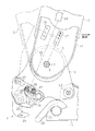
図2は、本実施形態の車両用シート1の骨格部の一部(車両用シートリクライニング装置)を示す側面図である。図2に示すように、下方には、シートクッション2(図1参照)の骨格をなし車両フロアに支持される第1フレームとしてのロアサイドフレーム11(その後端側の一部のみ図示)が配置され、該ロアサイドフレーム11の後端の上方には、シートバック3(図1参照)の骨格をなす第2フレームとしてのアッパサイドフレーム12が配置される。
FIG. 2 is a side view showing a part of the skeleton part (vehicle seat reclining device) of the
そして、図2に示すようにショルダーベルトアンカ3aが配置されない側(シート幅方向内側)において、前記ロアサイドフレーム11には第1アームとしてのロアアーム13が連結され、前記アッパサイドフレーム12には第2アームとしてのアッパアーム14が固定されている。そして、アッパアーム14とロアアーム13の間には、それらに挟まれた状態で公知のギヤ式のリクライナ15が接合されている。又、ショルダーベルトアンカ3aが配置される側(シート幅方向外側)においても略同様に、ロアアーム、アッパアーム、及びリクライナが設けられる構成とされている(図示略)。尚、ショルダーベルトアンカ3aが配置される側(シート幅方向外側)においては、一対のロアアーム間にアッパアームが配置され、アッパアームと両ロアアームとにそれぞれ挟まれた状態で接合される一対のリクライナを備えた構成としてもよい。
As shown in FIG. 2, on the side where the shoulder belt anchor 3 a is not disposed (inner side in the seat width direction), a
そして、ショルダーベルトアンカ3aが配置されない側(シート幅方向内側)のリクライナ15と、反対側(シート幅方向外側)のリクライナ(図示略)は、シャフト16にて連結されている。そして、例えば、シート幅方向内側のアッパアーム14に固定された駆動源としての電動モータ17(図2中、模式的に図示)の駆動力にてシャフト16が回転駆動されると、リクライナ15に結合されるロアアーム13とアッパアーム14とが相対回動されるように構成されている。よって、例えば、乗員は、図示しない操作手段の操作により電動モータ17を駆動することで、ロアサイドフレーム11(シートクッション2)に対するアッパサイドフレーム12(シートバック3)の傾斜角度を変更することが可能となっている。
The
ここで、ロアアーム13は、図2に示すように、リクライナ15の軸L1と平行な軸L2中心でロアサイドフレーム11に対して回動可能に連結されている。そして、ロアアーム13とロアサイドフレーム11には、ロアサイドフレーム11に対してロアアーム13を一方の回動端部まで回動させた状態で、互いに係合することで互いの回動(相対回動)を規制可能とするロック機構としてのラッチ機構21が設けられている。
Here, as shown in FIG. 2, the
詳述すると、ロアアーム13は、図2に示すように、リクライナ15よりも下方における前方側がリクライナ15の軸L1と平行な軸L2中心でロアサイドフレーム11に対して回動可能に連結されている。
More specifically, as shown in FIG. 2, the
又、ロアサイドフレーム11においてロアアーム13よりも下方における後方側端部には、図3及び図4に示すように、更に後方側に延びてその先端にリクライナ15の軸L1と平行に(図3及び図4中、紙面直交方向に)延びる略円柱状のストライカ22が形成されたストライカ部材23が固定されている。
Further, as shown in FIGS. 3 and 4, the
又、ロアアーム13においてリクライナ15よりも下方における後方側には、板状で該ロアアーム13と平行なプレート部材24が配置され、それらロアアーム13とプレート部材24との間には、ラッチ25がそれらを連結しつつ回動可能に支持されている。このラッチ25の下方には、前記ストライカ22と係合する(噛み合う)係合溝25aが形成されている。又、ラッチ25の上方には、自身の回動中心からの距離が変化するように段差部25bが形成されている。又、ロアアーム13とプレート部材24との間において、ラッチ25には、該ラッチ25と一体回動するラッチ一体プレート26が固定されている。ラッチ一体プレート26は、その一部が平面直交方向に突出形成されてロアアーム13に形成された長孔13a(図4参照)から外部(図4中、紙面手前側)に突出するばね固定片26aを有する。又、ラッチ一体プレート26の一部には、湾曲したカム面26bが形成されている。
A
又、ロアアーム13とプレート部材24との間には、ラッチ25がストライカ22と係合した状態でラッチ25の回動を係止可能(即ちラッチ25のストライカ22との係合状態を保持可能)とする係止プレート27が回動可能に支持されている。この係止プレート27は、図3及び図4に示すように、ラッチ25がストライカ22と係合した状態でラッチ25と噛合い該ラッチ25の回動を係止することで、ラッチ25のストライカ22との係合状態を保持して、ひいてはロアサイドフレーム11に対するロアアーム13の回動を規制するように構成されている。
Further, between the
又、ロアアーム13とプレート部材24との間には、その先端面が前記カム面26bと摺接して係合可能なカム部材28が回動可能に支持されている。このカム部材28の先端側には、プレート部材24に形成された長孔24aから外部(図3中、紙面手前側)に突出する突起部28aが設けられている。そして、カム部材28は、その突起部28aがプレート部材24に支持された捩りコイルばね29の付勢力によって付勢され、その付勢力によって自身の前記先端面がラッチ一体プレート26の前記カム面26bと係合し、ラッチ25がストライカ22を強固に挟み込むように(がたつきを防止しつつ保持するように)設けられている。
A
又、前記係止プレート27には、図4に示すように、ロアアーム13の外側(図4中、紙面手前側)に配置される操作プレート30が一体回動可能に連結されている。
そして、操作プレート30には、図4に示すように、ばね固定片30aが折曲げ形成され、そのばね固定片30aと前記ラッチ一体プレート26のばね固定片26aとには、それらを近づける側に付勢するばね31が連結されている。又、操作プレート30には、ワイヤ固定部30bが形成され、そのワイヤ固定部30bには、図2に模式的に示すように、ワイヤーケーブル32の一端が連結されている。このワイヤーケーブル32は、その他端が、例えば、前記シートバック3の背後に配置された操作手段としての操作レバー33に連結される。
Further, as shown in FIG. 4, an
As shown in FIG. 4, a
又、前記係止プレート27には、図3に示すように、プレート部材24の外側(図3中、紙面手前側)に配置され、その先端部がカム部材28の前記突起部28aと係合するカム解除レバー34が一体回動可能に連結されている。
Further, as shown in FIG. 3, the locking
そして、操作レバー33(ワイヤーケーブル32)が引っ張られた状態とされると、操作プレート30と共にカム解除レバー34及び係止プレート27が回動され、カム部材28の先端面が前記カム面26bから外れつつ、係止プレート27によるラッチ25の回動の係止が解除される(図5及び図6参照)。そして、この状態でシートバック3を前方側に倒れる方向に押すと、図5及び図6に示すように、ロアサイドフレーム11に対してロアアーム13が回動し、シートバック3が大きく前方側に倒れることになる。又、その後、操作レバー33(ワイヤーケーブル32)が引っ張られていない状態で、シートバック3を起こすように持ち上げると、図2〜図4に示すように、ラッチ25がストライカ22と係合する(噛み合う)とともに、係止プレート27がばね31の力で回動してラッチ25と噛合い該ラッチ25の回動が係止される。又、この際、カム部材28は、捩りコイルばね29の付勢力によって、その先端面がラッチ一体プレート26のカム面26bと係合し、ラッチ25はストライカ22を強固に挟み込むように(がたつきを防止しつつ保持するように)付勢される。これにより、ラッチ25のストライカ22との係合状態が(がたつきが防止されつつ)保持され、ひいてはロアサイドフレーム11に対するロアアーム13の回動が規制される。
When the operation lever 33 (wire cable 32) is pulled, the
又、本実施の形態のロアアーム13とプレート部材24との間には、図3及び図5に示すように、ラッチ機構21による規制が解除されたか否かを、該ラッチ機構21のラッチ25と直接係合して検出する解除検出センサとしてのリミットスイッチ41が設けられている。詳しくは、リミットスイッチ41は、ラッチ25の前記段差部25bと対応した位置に設けられ、図3に示すように、ラッチ25がストライカ22と係合し(噛み合い)ロアサイドフレーム11に対するロアアーム13の回動が規制された状態でオフ状態とされ、図5に示すように、前記規制が解除された状態でオン状態とされるように設けられている。そして、このリミットスイッチ41と前記電動モータ17とは、図2及び図6に示すように、制御部としてのシート用ECU42に電気的に接続されている。
Further, between the
前記シート用ECU42は、ラッチ機構21による規制が解除されると、ロアサイドフレーム11に対してロアアーム13を他方の回動端部まで回動させた状態でのロアサイドフレーム11(シートクッション2)に対するアッパサイドフレーム12(シートバック3)の傾斜角度を予め設定された設定角度範囲にすべく電動モータ17を駆動制御する。
When the regulation by the
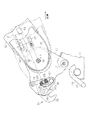
詳しくは、前記設定角度範囲は、シートバック3(アッパサイドフレーム12)が自重でシートクッション2側(前方側)に傾斜する範囲であって、本実施の形態では、図6に実線で示すように、アッパサイドフレーム12が垂直よりも前方側に約15°傾斜した傾斜角度位置に設定されている。
Specifically, the set angle range is a range in which the seat back 3 (upper side frame 12) is inclined by its own weight to the seat cushion 2 side (front side). In the present embodiment, as shown by a solid line in FIG. In addition, the
又、本実施の形態のシート用ECU42は、前記リミットスイッチ41からの信号に基づいて、ラッチ機構21による規制が解除されたか否かを判断する。
これにより、シート用ECU42は、例えばラッチ機構21による規制が解除される前のアッパサイドフレーム12(シートバック3)が後方側に大きく傾斜されていた場合(図2の2点鎖線参照)では、前記規制が解除されると、アッパサイドフレーム12(シートバック3)を図6に実線で示す傾斜角度位置にすべく電動モータ17を駆動制御する。
Further, the
Thereby, for example, when the upper side frame 12 (seat back 3) before the restriction by the
次に、上記実施の形態の特徴的な作用効果を以下に記載する。
(1)ロアアーム13(第1アーム)は、リクライナ15の軸L1と平行な軸L2中心でロアサイドフレーム11に対して回動可能に連結される。そして、ロアアーム13とロアサイドフレーム11には、ロアサイドフレーム11に対してロアアーム13を一方の回動端部まで回動させた状態で、互いの回動を規制可能とするラッチ機構21が設けられるため、その規制を解除することで、シートクッション2に対するシートバック3の傾斜角度を迅速に(手動で)変更することが可能となる。
Next, characteristic effects of the above embodiment will be described below.
(1) The lower arm 13 (first arm) is rotatably connected to the
しかも、ラッチ機構21による規制が解除されると、ロアサイドフレーム11に対してロアアーム13を他方の回動端部まで回動させた状態でのシートクッション2に対するシートバック3の傾斜角度を予め設定された設定角度範囲にすべく電動モータ17を駆動制御するシート用ECU42を備える。よって、前記傾斜角度を迅速に予め設定された所望の設定角度範囲に変更することが可能となる。
In addition, when the restriction by the
詳しくは、シート用ECU42がない場合、ロアサイドフレーム11に対してロアアーム13を他方の回動端部まで回動させた状態としても、その回動前のロアアーム13とアッパアーム14との相対回動角度の状態が保持されていることで、シートバック3の傾斜角度が所望の角度とならない虞があるが、これを解消することができる。
Specifically, when the
(2)前記設定角度範囲は、シートバック3(アッパサイドフレーム12)が自重でシートクッション2側(前方側)に傾斜する範囲に設定されるため、シートバック3をシートクッション2側(前方側)に倒れた状態とすることができる。即ち、図2に2点鎖線で示すようにアッパサイドフレーム12が後方側に大きく傾斜された状態においてロアアーム13を他方の回動端部まで回動させた状態としても、アッパサイドフレーム12の傾斜角度が前方側に倒れた状態とならない(図6の2点鎖線参照)虞があるが、これを解消してシートバック3を前方側に倒れた状態とすることができる。その結果、例えば、車両後方側の座席を仕切るように配置されるシートバック3を迅速に前方側に倒れた状態とすることができ、車両後方側の座席にいた乗員が車両前方側に配置されるドアから迅速に車外に出ることが可能となる。又、シートバック3は、自重でシートクッション2側(前方側)に倒れた状態で保持されるため、例えば、車両後方側の座席にいた乗員は、シートバック3から手を離した状態で車両前方側に配置されるドアから迅速に車外に出ることが可能となる。
(2) The set angle range is set to a range in which the seat back 3 (upper side frame 12) is inclined by its own weight to the seat cushion 2 side (front side), and therefore the seat back 3 is set to the seat cushion 2 side (front side). ). That is, even if the
(3)ラッチ機構21による規制が解除されたか否かを、該ラッチ機構21(そのラッチ25)と直接係合して検出するリミットスイッチ41を備えるため、例えば、実際にラッチ機構21による規制が解除されていないのにシート用ECU42が電動モータ17を駆動制御してしまうことが防止される。即ち、例えば前記操作レバー33を操作したことを検出するセンサを備えたものとすると、操作レバー33からラッチ機構21までの経路上やラッチ機構21自体の故障等が原因で操作レバー33を操作しても前記規制が解除されない場合でもシート用ECU42が電動モータ17を駆動制御してしまう虞があるが、それを防止することができる。
(3) Since the
上記実施の形態は、以下のように変更してもよい。
・上記実施の形態では、特に言及していないが、前記シート用ECU42がない場合では、シートバック3(アッパサイドフレーム12)の傾斜角度が前方側に大きく倒れ過ぎた状態となる(図8の2点鎖線参照)虞があるような構成でも、大きく倒れ過ぎた状態とならないようにすることが可能となる。
The above embodiment may be modified as follows.
In the above embodiment, although not particularly mentioned, when the
例えば、シート用ECU42は、図7の2点鎖線に示すように、アッパサイドフレーム12(シートバック3)が略垂直状態とされていた場合等では、前記規制が解除されると、アッパサイドフレーム12(シートバック3)を図8に実線で示す傾斜角度位置にすべく電動モータ17を駆動制御するようにしてもよい。
For example, when the upper side frame 12 (seat back 3) is in a substantially vertical state as shown by a two-dot chain line in FIG. 7, the
このようにすると、例えば、シート用ECU42がない場合ではアッパサイドフレーム12(シートバック3)の傾斜角度が前方側に大きく倒れ過ぎた状態(図8中、2点鎖線参照)となり後にシートバック3を持ち上げる動作に大きな力が必要となる虞があるが、これを解消してシートバック3を容易に着座可能な状態に復帰させることが可能となる。又、上記実施の形態では、その範囲から外れると電動モータ17を駆動制御する前記設定角度範囲を、アッパサイドフレーム12が垂直よりも前方側に約15°傾斜した傾斜角度位置に設定したが、例えば、垂直よりも前方側に約20°傾斜した傾斜角度位置や、垂直よりも前方側に15°〜70°傾斜した傾斜角度範囲等の他の値に設定してもよい。
In this case, for example, when there is no
・上記実施の形態では、特に言及していないが、シート用ECU42は、ロアサイドフレーム11に対してロアアーム13が一方の回動端部まで回動されてラッチ機構21による規制が行われると、該ラッチ機構21による規制が解除された際に電動モータ17を駆動制御した分だけ該電動モータ17を逆方向に駆動制御するようにしてもよい。
In the above embodiment, although not particularly mentioned, when the
このようにすると、シートバック3(アッパサイドフレーム12)の傾斜角度がラッチ機構21による規制を解除する前の元の位置に復帰される。よって、その車両用シート1には、再び同じ体勢で着座可能となる。尚、勿論、これに限定されず、ラッチ機構21による規制が行われても、元の位置に復帰させない(電動モータ17を逆方向に駆動制御しない)ようにしてもよい。
In this way, the inclination angle of the seat back 3 (upper side frame 12) is returned to the original position before the restriction by the
・上記実施の形態では、ラッチ機構21による規制が解除されたか否かを、該ラッチ機構21(そのラッチ25)と直接係合して検出するリミットスイッチ41からの信号にて判定する構成としたが、これに限定されず、例えば、操作レバー33(操作手段)を操作したことを検出するセンサの信号にて判定する構成としてもよい。
In the above embodiment, it is determined whether or not the restriction by the
・上記実施の形態では、制御部はシート用ECU42であるとしたが、同様の制御を行うことができれば、例えば、他のセンサや単純な回路素子等を組み合わせてマイクロコンピューターを用いずに制御部を構成してもよい。
In the above embodiment, the control unit is the
・上記実施の形態では、第1フレームは、シートクッション2の骨格をなすロアサイドフレーム11であり、第1アームとしてのロアアーム13がロアサイドフレーム11に対して回動可能に連結される構成としたが、第1フレームをアッパサイドフレームとするとともに第1アームをアッパアームとしてそれらを回動可能に連結した構成としてもよい。尚、勿論、この場合、第2フレームがロアサイドフレームで第2アームがロアアームとなり、ロック機構(ラッチ機構)はアッパサイドフレームとアッパアームに設けられることになる。
In the above embodiment, the first frame is the
次に、上記実施形態及び別例から把握できる技術的思想について以下に追記する。
(イ)請求項3に記載の車両用シートリクライニング装置において、前記ロック機構は、ラッチとストライカで回動を規制するラッチ機構であり、前記解除検出センサは、前記ラッチと直接係合するリミットスイッチであることを特徴とする車両用シートリクライニング装置。
Next, the technical idea that can be grasped from the above embodiment and other examples will be described below.
(A) In the vehicle seat reclining device according to
同構成によれば、前記ロック機構は、ラッチとストライカで回動を規制するラッチ機構であり、前記解除検出センサは、前記ラッチと直接係合するリミットスイッチであるため、簡単な構成で請求項3に記載の発明の効果を得ることができる。 According to this configuration, the lock mechanism is a latch mechanism that restricts rotation by a latch and a striker, and the release detection sensor is a limit switch that is directly engaged with the latch. The effect of the invention described in 3 can be obtained.
(ロ)請求項1乃至3及び上記(イ)のいずれか1つに記載のシートリクライニング装置において、前記制御部は、前記第1フレームに対して前記第1アームが一方の回動端部まで回動されて前記ロック機構による規制が行われると、前記ロック機構による規制が解除された際に前記駆動源を駆動制御した分だけ前記駆動源を逆方向に駆動制御することを特徴とするシートリクライニング装置。
(B) In the seat reclining device according to any one of
同構成によれば、制御部により、第1フレームに対して第1アームが一方の回動端部まで回動されてロック機構による規制が行われると、ロック機構による規制が解除された際に駆動源を駆動制御した分だけ駆動源が逆方向に駆動制御されるため、シートバックの傾斜角度がロック機構による規制を解除する前の元の位置に復帰される。よって、その車両用シートには、再び同じ体勢で着座可能となる。 According to this configuration, when the control unit rotates the first arm to the one rotation end with respect to the first frame and the restriction by the lock mechanism is performed, the restriction by the lock mechanism is released. Since the drive source is driven and controlled in the reverse direction by the drive control of the drive source, the inclination angle of the seat back is returned to the original position before the restriction by the lock mechanism is released. Therefore, the vehicle seat can be seated again in the same posture.
2…シートクッション、3…シートバック、11…ロアサイドフレーム(第1フレーム)、12…アッパサイドフレーム(第2フレーム)、13…ロアアーム(第1アーム)、14…アッパアーム(第2アーム)、15…リクライナ、17…電動モータ(駆動源)、21…ラッチ機構(ロック機構)、41…リミットスイッチ(解除検出センサ)、42…シート用ECU(制御部)。
2 ... Seat cushion, 3 ... Seat back, 11 ... Lower side frame (first frame), 12 ... Upper side frame (second frame), 13 ... Lower arm (first arm), 14 ... Upper arm (second arm), DESCRIPTION OF
Claims (3)
前記シートクッション及び前記シートバックの他方の骨格をなす第2フレームに固定される第2アームと、
前記第2アームと前記第1アームとに挟まれた状態で接合されるリクライナと、
前記シートクッションに対する前記シートバックの傾斜角度を変更すべく前記第1アームと前記第2アームとを相対回動させる駆動源と
を備えた車両用シートリクライニング装置であって、
前記第1アームは、前記リクライナの軸と平行な軸中心で前記第1フレームに対して回動可能に連結され、
前記第1アームと前記第1フレームには、前記第1フレームに対して前記第1アームを一方の回動端部まで回動させた状態で、互いに係合することで互いの回動を規制可能とするロック機構が設けられ、
前記ロック機構による規制が解除されると、前記第1フレームに対して前記第1アームを他方の回動端部まで回動させた状態での前記シートクッションに対する前記シートバックの傾斜角度を予め設定された設定角度範囲にすべく前記駆動源を駆動制御する制御部を備えたことを特徴とするシートリクライニング装置。 A first arm connected to a first frame forming one skeleton of the seat cushion and the seat back;
A second arm fixed to a second frame forming the other skeleton of the seat cushion and the seat back;
A recliner joined in a state sandwiched between the second arm and the first arm;
A vehicle seat reclining device comprising: a drive source that relatively rotates the first arm and the second arm to change an inclination angle of the seat back with respect to the seat cushion;
The first arm is rotatably connected to the first frame at an axis center parallel to the recliner axis;
The first arm and the first frame are restrained from rotating by being engaged with each other in a state where the first arm is rotated to one rotating end with respect to the first frame. A locking mechanism is provided that enables
When the restriction by the lock mechanism is released, an inclination angle of the seat back with respect to the seat cushion in a state where the first arm is rotated to the other rotation end with respect to the first frame is set in advance. A seat reclining device comprising: a control unit that drives and controls the drive source so as to be within a set angle range.
前記設定角度範囲は、前記シートバックが自重で前記シートクッション側に傾斜する範囲に設定されたことを特徴とするシートリクライニング装置。 The seat reclining device according to claim 1,
The seat reclining device, wherein the set angle range is set to a range in which the seat back is inclined by its own weight toward the seat cushion side.
前記ロック機構による規制が解除されたか否かを該ロック機構と直接係合して検出する解除検出センサを備えたことを特徴とするシートリクライニング装置。 In the seat reclining device according to claim 1 or 2,
A seat reclining device comprising: a release detection sensor that detects whether or not the restriction by the lock mechanism is released by directly engaging the lock mechanism.
Priority Applications (4)
| Application Number | Priority Date | Filing Date | Title |
|---|---|---|---|
| JP2011002364A JP5655574B2 (en) | 2011-01-07 | 2011-01-07 | Vehicle seat reclining device |
| US13/326,752 US8511750B2 (en) | 2011-01-07 | 2011-12-15 | Vehicle seat device |
| CN2011104395425A CN102582476A (en) | 2011-01-07 | 2011-12-23 | Vehicle seat device |
| EP11195728.8A EP2474439A3 (en) | 2011-01-07 | 2011-12-26 | Vehicle seat device |
Applications Claiming Priority (1)
| Application Number | Priority Date | Filing Date | Title |
|---|---|---|---|
| JP2011002364A JP5655574B2 (en) | 2011-01-07 | 2011-01-07 | Vehicle seat reclining device |
Publications (2)
| Publication Number | Publication Date |
|---|---|
| JP2012144085A true JP2012144085A (en) | 2012-08-02 |
| JP5655574B2 JP5655574B2 (en) | 2015-01-21 |
Family
ID=45464361
Family Applications (1)
| Application Number | Title | Priority Date | Filing Date |
|---|---|---|---|
| JP2011002364A Expired - Fee Related JP5655574B2 (en) | 2011-01-07 | 2011-01-07 | Vehicle seat reclining device |
Country Status (4)
| Country | Link |
|---|---|
| US (1) | US8511750B2 (en) |
| EP (1) | EP2474439A3 (en) |
| JP (1) | JP5655574B2 (en) |
| CN (1) | CN102582476A (en) |
Cited By (1)
| Publication number | Priority date | Publication date | Assignee | Title |
|---|---|---|---|---|
| JP2019202696A (en) * | 2018-05-25 | 2019-11-28 | トヨタ紡織株式会社 | Control method for vehicle seat |
Families Citing this family (8)
| Publication number | Priority date | Publication date | Assignee | Title |
|---|---|---|---|---|
| JP5591664B2 (en) * | 2010-11-29 | 2014-09-17 | トヨタ紡織株式会社 | Vehicle seat |
| CN103241144B (en) * | 2013-04-22 | 2016-05-25 | 芜湖瑞泰汽车零部件有限公司 | The bilateral recliner synchronization structure of a kind of automotive seat |
| JP6112359B2 (en) * | 2013-09-19 | 2017-04-12 | アイシン精機株式会社 | Vehicle seat |
| DE102014208076A1 (en) * | 2013-10-23 | 2015-05-07 | Johnson Controls Components Gmbh & Co. Kg | Electrically operated backrest adjuster and vehicle seat with such a backrest adjuster |
| KR20170005790A (en) | 2013-11-24 | 2017-01-16 | 하마마, 야니브 | Slim-form charger for a mobile phone |
| US9758060B2 (en) * | 2016-01-21 | 2017-09-12 | Honda Motor Co., Ltd. | Seat with recliner limit switch assembly and method of use thereof |
| WO2017203366A1 (en) * | 2016-05-27 | 2017-11-30 | Mobile Synergy 26 International Limited | Multifunctional connection systems for various devices and methods of use thereof |
| US10611273B2 (en) * | 2017-10-09 | 2020-04-07 | Faurecia Automotive Seating, Llc | Recliner system for a vehicle seat |
Citations (5)
| Publication number | Priority date | Publication date | Assignee | Title |
|---|---|---|---|---|
| JPS59135018A (en) * | 1982-12-24 | 1984-08-03 | カイパ−・レカロ・ゲゼルシヤフト・ミツト・ベシユレンクテル・ハフツング・ウント・コンパニ− | Hinge mechanism of vehicle seat |
| JPH02256530A (en) * | 1989-03-29 | 1990-10-17 | Toyo Sheet:Kk | Seat device for vehicle |
| US6352310B1 (en) * | 1999-03-08 | 2002-03-05 | Daimlerchrysler Ag | Vehicle seat |
| JP2004249963A (en) * | 2002-12-26 | 2004-09-09 | Honda Motor Co Ltd | Automatically rotating and stowing system for vehicle seat |
| JP2010247575A (en) * | 2009-04-13 | 2010-11-04 | Toyota Boshoku Corp | Seat for vehicle |
Family Cites Families (12)
| Publication number | Priority date | Publication date | Assignee | Title |
|---|---|---|---|---|
| US5435624A (en) * | 1993-10-12 | 1995-07-25 | Ford Motor Company | Powered vehicle seat |
| DE19931894B4 (en) * | 1999-07-08 | 2005-06-30 | Key Safety Systems, Inc., Sterling Heights | vehicle seat |
| JP4105166B2 (en) * | 2003-01-03 | 2008-06-25 | ジョンソン コントロールズ テクノロジー カンパニー | Car seat with control system |
| DE10315375A1 (en) * | 2003-04-03 | 2004-11-11 | Keiper Gmbh & Co. Kg | Fitting system for a vehicle seat |
| US7152922B2 (en) * | 2004-05-07 | 2006-12-26 | Fisher Dynamics Corporation | Powered remote release actuator for a seat assembly |
| JP4770389B2 (en) * | 2005-10-21 | 2011-09-14 | アイシン精機株式会社 | Vehicle seat device |
| DE102005058367C5 (en) * | 2005-12-06 | 2012-02-09 | Faurecia Autositze Gmbh | vehicle seat |
| US7823972B2 (en) * | 2006-11-01 | 2010-11-02 | Gm Global Technology Operations, Inc. | Recliner adjustment utilizing active material sensors |
| WO2008132998A1 (en) * | 2007-04-16 | 2008-11-06 | Toyota Boshoku Kabushiki Kaisha | Vehicle seat |
| EP2190688B1 (en) * | 2007-09-10 | 2011-09-07 | Johnson Controls Technology Company | Vehicle seat power track enhancements |
| CN101883697B (en) * | 2007-12-03 | 2012-08-15 | 丰田纺织株式会社 | Vehicle seat |
| JP5380858B2 (en) | 2008-02-27 | 2014-01-08 | アイシン精機株式会社 | Vehicle seat reclining device |
-
2011
- 2011-01-07 JP JP2011002364A patent/JP5655574B2/en not_active Expired - Fee Related
- 2011-12-15 US US13/326,752 patent/US8511750B2/en not_active Expired - Fee Related
- 2011-12-23 CN CN2011104395425A patent/CN102582476A/en active Pending
- 2011-12-26 EP EP11195728.8A patent/EP2474439A3/en not_active Withdrawn
Patent Citations (5)
| Publication number | Priority date | Publication date | Assignee | Title |
|---|---|---|---|---|
| JPS59135018A (en) * | 1982-12-24 | 1984-08-03 | カイパ−・レカロ・ゲゼルシヤフト・ミツト・ベシユレンクテル・ハフツング・ウント・コンパニ− | Hinge mechanism of vehicle seat |
| JPH02256530A (en) * | 1989-03-29 | 1990-10-17 | Toyo Sheet:Kk | Seat device for vehicle |
| US6352310B1 (en) * | 1999-03-08 | 2002-03-05 | Daimlerchrysler Ag | Vehicle seat |
| JP2004249963A (en) * | 2002-12-26 | 2004-09-09 | Honda Motor Co Ltd | Automatically rotating and stowing system for vehicle seat |
| JP2010247575A (en) * | 2009-04-13 | 2010-11-04 | Toyota Boshoku Corp | Seat for vehicle |
Cited By (2)
| Publication number | Priority date | Publication date | Assignee | Title |
|---|---|---|---|---|
| JP2019202696A (en) * | 2018-05-25 | 2019-11-28 | トヨタ紡織株式会社 | Control method for vehicle seat |
| JP7049184B2 (en) | 2018-05-25 | 2022-04-06 | トヨタ紡織株式会社 | How to control the vehicle seat |
Also Published As
| Publication number | Publication date |
|---|---|
| CN102582476A (en) | 2012-07-18 |
| EP2474439A3 (en) | 2017-02-01 |
| EP2474439A2 (en) | 2012-07-11 |
| US20120175932A1 (en) | 2012-07-12 |
| JP5655574B2 (en) | 2015-01-21 |
| US8511750B2 (en) | 2013-08-20 |
Similar Documents
| Publication | Publication Date | Title |
|---|---|---|
| JP5655574B2 (en) | Vehicle seat reclining device | |
| US7472963B2 (en) | Recliner lever assembly for a front seat of a vehicle | |
| US7699399B2 (en) | Seat apparatus | |
| JP2004352135A (en) | Vehicular seat | |
| US7931332B2 (en) | Rear-seat occupant protection apparatus | |
| US9358951B2 (en) | Seatbelt retractor | |
| EP2777984A1 (en) | Vehicle head restraint with electromagnetic latch release | |
| JP6690408B2 (en) | Seat adjuster | |
| JP5707817B2 (en) | Vehicle seat reclining device | |
| JP2009090807A (en) | Vehicular storage seat | |
| US20050006920A1 (en) | Seat apparatus | |
| JP2006282019A (en) | Height adjusting device for automobile seat | |
| JP4602898B2 (en) | Seat belt device | |
| JP3589652B2 (en) | Safety mechanism for vehicle seat | |
| JP2012240554A (en) | Vehicle seat | |
| JP2006315623A (en) | Vehicle seat | |
| JP5684008B2 (en) | Vehicle seat | |
| JPH05105028A (en) | Seat buckle interference preventing device | |
| JP2003048510A (en) | Seat belt structure for front seat of vehicle | |
| WO2012043602A1 (en) | Seat-reclining device for use in vehicle | |
| JP2017226336A (en) | Seat for vehicle | |
| JP2007209596A (en) | Seat device for automobile | |
| JP2011073621A (en) | Foldable seat device | |
| JP5344387B2 (en) | Sheet | |
| JPH0569769A (en) | Seat device for automobile |
Legal Events
| Date | Code | Title | Description |
|---|---|---|---|
| A621 | Written request for application examination |
Free format text: JAPANESE INTERMEDIATE CODE: A621 Effective date: 20131205 |
|
| A977 | Report on retrieval |
Free format text: JAPANESE INTERMEDIATE CODE: A971007 Effective date: 20141020 |
|
| TRDD | Decision of grant or rejection written | ||
| A01 | Written decision to grant a patent or to grant a registration (utility model) |
Free format text: JAPANESE INTERMEDIATE CODE: A01 Effective date: 20141028 |
|
| A61 | First payment of annual fees (during grant procedure) |
Free format text: JAPANESE INTERMEDIATE CODE: A61 Effective date: 20141110 |
|
| R151 | Written notification of patent or utility model registration |
Ref document number: 5655574 Country of ref document: JP Free format text: JAPANESE INTERMEDIATE CODE: R151 |
|
| LAPS | Cancellation because of no payment of annual fees |