JP4105166B2 - Car seat with control system - Google Patents
Car seat with control system Download PDFInfo
- Publication number
- JP4105166B2 JP4105166B2 JP2004566416A JP2004566416A JP4105166B2 JP 4105166 B2 JP4105166 B2 JP 4105166B2 JP 2004566416 A JP2004566416 A JP 2004566416A JP 2004566416 A JP2004566416 A JP 2004566416A JP 4105166 B2 JP4105166 B2 JP 4105166B2
- Authority
- JP
- Japan
- Prior art keywords
- seat
- base
- seat base
- seat back
- control circuit
- Prior art date
- Legal status (The legal status is an assumption and is not a legal conclusion. Google has not performed a legal analysis and makes no representation as to the accuracy of the status listed.)
- Expired - Fee Related
Links
- 230000007246 mechanism Effects 0.000 claims abstract description 30
- 230000004044 response Effects 0.000 claims abstract description 14
- 230000008859 change Effects 0.000 claims abstract description 4
- 239000000758 substrate Substances 0.000 claims 1
- 238000010586 diagram Methods 0.000 description 8
- 230000006870 function Effects 0.000 description 8
- 230000005484 gravity Effects 0.000 description 6
- 230000005355 Hall effect Effects 0.000 description 5
- 239000000872 buffer Substances 0.000 description 3
- 230000001052 transient effect Effects 0.000 description 3
- 230000008901 benefit Effects 0.000 description 2
- 239000003990 capacitor Substances 0.000 description 2
- 230000000694 effects Effects 0.000 description 2
- 238000005516 engineering process Methods 0.000 description 2
- WABPQHHGFIMREM-UHFFFAOYSA-N lead(0) Chemical compound [Pb] WABPQHHGFIMREM-UHFFFAOYSA-N 0.000 description 2
- 238000000034 method Methods 0.000 description 2
- 238000012935 Averaging Methods 0.000 description 1
- 230000008878 coupling Effects 0.000 description 1
- 238000010168 coupling process Methods 0.000 description 1
- 238000005859 coupling reaction Methods 0.000 description 1
- 230000005669 field effect Effects 0.000 description 1
- 230000001939 inductive effect Effects 0.000 description 1
- 230000002452 interceptive effect Effects 0.000 description 1
- 230000007774 longterm Effects 0.000 description 1
- 210000004705 lumbosacral region Anatomy 0.000 description 1
- 238000005259 measurement Methods 0.000 description 1
- 238000012986 modification Methods 0.000 description 1
- 230000004048 modification Effects 0.000 description 1
- 238000012545 processing Methods 0.000 description 1
- 230000002441 reversible effect Effects 0.000 description 1
Images


Classifications
-
- B—PERFORMING OPERATIONS; TRANSPORTING
- B60—VEHICLES IN GENERAL
- B60N—SEATS SPECIALLY ADAPTED FOR VEHICLES; VEHICLE PASSENGER ACCOMMODATION NOT OTHERWISE PROVIDED FOR
- B60N2/00—Seats specially adapted for vehicles; Arrangement or mounting of seats in vehicles
- B60N2/02—Seats specially adapted for vehicles; Arrangement or mounting of seats in vehicles the seat or part thereof being movable, e.g. adjustable
- B60N2/0224—Non-manual adjustments, e.g. with electrical operation
- B60N2/0244—Non-manual adjustments, e.g. with electrical operation with logic circuits
- B60N2/0252—Non-manual adjustments, e.g. with electrical operation with logic circuits with relations between different adjustments, e.g. height of headrest following longitudinal position of seat
-
- B—PERFORMING OPERATIONS; TRANSPORTING
- B60—VEHICLES IN GENERAL
- B60N—SEATS SPECIALLY ADAPTED FOR VEHICLES; VEHICLE PASSENGER ACCOMMODATION NOT OTHERWISE PROVIDED FOR
- B60N2/00—Seats specially adapted for vehicles; Arrangement or mounting of seats in vehicles
- B60N2/02—Seats specially adapted for vehicles; Arrangement or mounting of seats in vehicles the seat or part thereof being movable, e.g. adjustable
- B60N2/0224—Non-manual adjustments, e.g. with electrical operation
- B60N2/02246—Electric motors therefor
-
- B—PERFORMING OPERATIONS; TRANSPORTING
- B60—VEHICLES IN GENERAL
- B60N—SEATS SPECIALLY ADAPTED FOR VEHICLES; VEHICLE PASSENGER ACCOMMODATION NOT OTHERWISE PROVIDED FOR
- B60N2/00—Seats specially adapted for vehicles; Arrangement or mounting of seats in vehicles
- B60N2/02—Seats specially adapted for vehicles; Arrangement or mounting of seats in vehicles the seat or part thereof being movable, e.g. adjustable
- B60N2/04—Seats specially adapted for vehicles; Arrangement or mounting of seats in vehicles the seat or part thereof being movable, e.g. adjustable the whole seat being movable
- B60N2/06—Seats specially adapted for vehicles; Arrangement or mounting of seats in vehicles the seat or part thereof being movable, e.g. adjustable the whole seat being movable slidable
- B60N2/067—Seats specially adapted for vehicles; Arrangement or mounting of seats in vehicles the seat or part thereof being movable, e.g. adjustable the whole seat being movable slidable by linear actuators, e.g. linear screw mechanisms
-
- B—PERFORMING OPERATIONS; TRANSPORTING
- B60—VEHICLES IN GENERAL
- B60N—SEATS SPECIALLY ADAPTED FOR VEHICLES; VEHICLE PASSENGER ACCOMMODATION NOT OTHERWISE PROVIDED FOR
- B60N2/00—Seats specially adapted for vehicles; Arrangement or mounting of seats in vehicles
- B60N2/02—Seats specially adapted for vehicles; Arrangement or mounting of seats in vehicles the seat or part thereof being movable, e.g. adjustable
- B60N2/22—Seats specially adapted for vehicles; Arrangement or mounting of seats in vehicles the seat or part thereof being movable, e.g. adjustable the back-rest being adjustable
Abstract
Description
本発明は、概略、自動車シートの分野に関し、より詳細には、本発明は、柔軟性部材を有するシートバックを備える自動車シートに関する。 The present invention relates generally to the field of automobile seats, and more particularly, the invention relates to an automobile seat comprising a seat back having a flexible member.
本出願は、2003年1月3日出願の米国特許仮出願60/437,804に基づく優先権を主張し、該出願の開示は、明示的に参照により本出願の一部をなす。
This application claims priority from US
自動車シート産業以外においては、制御された曲線型屈曲支持を提供するため、少なくとも2箇所の垂直方向に離隔した位置で、シートバックフレームアセンブリに枢支取り付けされる従属シートバックを有する椅子を提供することが公知である。 Outside the automotive seat industry, a chair is provided having a subordinate seat back pivotally attached to a seat back frame assembly at at least two vertically spaced locations to provide controlled curved flexural support. It is known.
リクライン可能なバックを有する自動車シートを提供することが知られている。リクライン可能なバックと、独立して移動可能なシート基部とを有する自動車シートを提供することもまた、知られている。括り付けられた第1端と、該第1端に対して移動する第2端とを有する柔軟性部材からなり、該柔軟部材の形状を変化させて自動車シートのランバー領域内に調節可能な支持を提供する調節可能なランバーを有する自動車シートもまた、知られている。シート基部及びシートバックを同時に移動させて、所望の最終位置を達成することもまた、知られている。例えば、これは、自動車シートがユーザーのシート位置を記憶するよう機能する状況において、所望され、これにより、その位置が変更された場合にシートがユーザーの所望する位置まで戻ることを可能にする。しかしながら、本技術分野におけるいかなる引用例も、シートバック及びシート基部の移動の間にあるいかなる関係をも教示するものではない。 It is known to provide an automobile seat having a reclinable back. It is also known to provide an automobile seat having a reclinable back and an independently movable seat base. A flexible member having a tightly bound first end and a second end that moves relative to the first end, the support being adjustable within the lumbar region of the vehicle seat by changing the shape of the flexible member Automotive seats with adjustable lumbars that provide are also known. It is also known to move the seat base and the seat back simultaneously to achieve the desired final position. For example, this is desired in situations where an automobile seat functions to store a user's seat position, thereby allowing the seat to return to the user's desired position if that position is changed. However, any reference in the art does not teach any relationship between seat back and seat base movement.
公知の装置の存在にもかかわらず、シートの搭乗者をより良好に支持することのできる自動車シートを開発する顕著な要請が依然として存在する。特に、複数シート搭乗者の複数のサイズへの連続的な支持を提供することのできる自動車シートを提供する要請が存在する。さらに、搭乗者の変化する形状及び姿勢に適合可能であることを含む、搭乗者の固有の形状及び姿勢に自動的に適合する、柔軟性シートバックを含む自動車シートを提供する要請が存在する。さらに、搭乗者に、個人に合わせた支持を提供し、後方及び脊柱運動を許容するシートバックを有する自動車シートを提供する要請が存在する。 Despite the presence of known devices, there remains a significant need to develop automotive seats that can better support seat occupants. In particular, there is a need to provide an automobile seat that can provide continuous support for multiple seat passengers to multiple sizes. Furthermore, there is a need to provide an automobile seat that includes a flexible seat back that automatically adapts to the unique shape and attitude of the occupant, including being adaptable to the changing shape and attitude of the occupant. In addition, there is a need to provide passengers with a car seat having a seat back that provides personalized support and allows posterior and spinal motion.
搭乗者に関してより自然に枢支回動可能であり、搭乗者に接触したランバー支持をより良好に維持することのできるシートバックを有する自動車シートを提供する要請もまた、存在する。 There is also a need to provide an automobile seat having a seat back that is more naturally pivotable with respect to the occupant and that can better maintain lumbar support in contact with the occupant.
1つ又は複数のこれら或いは他の有利な特徴を提供する自動車シートを提供することが所望される。他の特徴及び利点は、本発明の開示から容易に理解される。開示された教示は、上記の要請の1つ又は複数を達成するか否かに拘わりなく、クレームの範囲内にあるその実施形態にまで及ぶ。 It would be desirable to provide an automobile seat that provides one or more of these or other advantageous features. Other features and advantages are readily apparent from the present disclosure. The disclosed teachings extend to their embodiments that are within the scope of the claims, whether or not they achieve one or more of the above-mentioned needs.
ある例示的実施形態によれば、シート基部と、シート基部モーターと、シートバックと、手動リクライナー機構と、及び制御回路とを含む車両シート用制御システムが提供される。このシート基部モーターは、シート基部を前方及び後方に移動するよう構成される。この手動リクライナー機構は、シートバックの傾斜角度を調整するよう構成される。この制御回路は、この傾斜角度の変更に応じて、シート基部を前方或いは後方に移動するよう構成される。 According to an exemplary embodiment, a vehicle seat control system is provided that includes a seat base, a seat base motor, a seat back, a manual recliner mechanism, and a control circuit. The seat base motor is configured to move the seat base forward and backward. This manual recliner mechanism is configured to adjust the tilt angle of the seat back. The control circuit is configured to move the seat base forward or backward in accordance with the change in the tilt angle.
他の例示的実施形態によれば、シート基部と、シート基部モーターと、シートバックと、手動リクライナー機構と、及び制御回路とを含む車両シート用の制御システムが提供される。このシート基部モーターは、シート基部を前方及び後方に移動するよう構成される。この手動リクライナー機構は、シートバックの傾斜角度を調整するよう構成される。この制御回路は、シートバックの移動に応じて、シート基部を移動するよう構成され、このシートバックは、シート基部の約1mmから約4mmの前方或いは後方移動に対して、約1度の傾斜角度の比率で移動される。 According to another exemplary embodiment, a control system for a vehicle seat is provided that includes a seat base, a seat base motor, a seat back, a manual recliner mechanism, and a control circuit. The seat base motor is configured to move the seat base forward and backward. This manual recliner mechanism is configured to adjust the tilt angle of the seat back. The control circuit is configured to move the seat base in response to movement of the seat back, and the seat back has an inclination angle of about 1 degree with respect to a forward or backward movement of about 1 mm to about 4 mm of the seat base. It is moved by the ratio.
他の例示的実施形態によれば、トラックと、シート基部と、シート基部モーターと、シートバックと、手動リクライナー機構と、シート基部入力装置と、制御回路とを含む制御システムを有する車両シートが提供される。このシート基部は、トラックに結合される。このシート基部モーターは、シート基部を前方及び後方に移動するよう構成される。このシートバックはトラックに、枢支結合される。この手動リクライナー機構は、トラックに対して、シートバックを枢支回動するよう構成される。このシート基部入力装置は、シート基部を移動するオペレータコマンドを受信するよう構成される。この制御回路は、シート基部入力装置からオペレータコマンドを受信し、シート基部モーターを制御するよう構成れる。この制御回路は、シートバックの移動に応じて、シート基部を移動するよう構成されてよい。この制御回路はまた、シート基部入力装置からのコマンド受信に応答して、シート基部のみを移動するよう構成されてもよい。 According to another exemplary embodiment, a vehicle seat is provided having a control system that includes a truck, a seat base, a seat base motor, a seat back, a manual recliner mechanism, a seat base input device, and a control circuit. Is done. The seat base is coupled to the track. The seat base motor is configured to move the seat base forward and backward. This seat back is pivotally connected to the truck. The manual recliner mechanism is configured to pivot the seat back relative to the track. The sheet base input device is configured to receive an operator command to move the sheet base. The control circuit is configured to receive an operator command from the seat base input device and control the seat base motor. The control circuit may be configured to move the seat base as the seat back moves. The control circuit may also be configured to move only the seat base in response to receiving a command from the seat base input device.
他の例示的実施形態によれば、トラックと、このトラックに結合されるシート基部と、このトラックに枢支結合されるシートバックと、シート基部及びシートバック入力装置と、及び制御回路とを含む電子制御システムを有する車両シートが提供される。このシート基部は、シート基部を前方及び後方に移動するよう構成されるシート基部モーターを有する。このシートバックは、シートバックの傾斜角度を調整するよう構成されるシートバックモーターを有する。このシート基部入力装置は、シート基部を移動するオペレータコマンドを受信するよう構成される。このシートバック入力装置は、シートバックを移動するオペレータコマンドを受信するよう構成される。この制御回路は、オペレータコマンドを受信して、シート基部モーター及びシートバックモーターを制御するよう構成される。この制御回路は、シートバック入力装置からのコマンド受信に応じて、シート基部及びシートバックの双方を移動し、及び、シート基部入力装置からのコマンド受信に応じて、シート基部のみを移動するよう構成される。 According to another exemplary embodiment, includes a track, a seat base coupled to the track, a seat back pivotally coupled to the track, a seat base and seat back input device, and a control circuit. A vehicle seat having an electronic control system is provided. The seat base includes a seat base motor configured to move the seat base forward and backward. The seat back includes a seat back motor configured to adjust a tilt angle of the seat back. The sheet base input device is configured to receive an operator command to move the sheet base. The seat back input device is configured to receive an operator command to move the seat back. The control circuit is configured to receive an operator command and control the seat base motor and the seat back motor. The control circuit is configured to move both the seat base and the seat back in response to command reception from the seat back input device, and to move only the seat base in response to command reception from the seat base input device. Is done.
ある有利な特徴によれば、制御回路は、シートバック入力装置からのコマンド受信に応じて、シート基部を第1のスピードで移動し、シート基部入力装置からのコマンド受信に応じて、シート基部を第1のスピードより速い第2のスピードで移動するよう構成される。 According to one advantageous feature, the control circuit moves the seat base at a first speed in response to receiving a command from the seat back input device and moves the seat base in response to receiving a command from the seat base input device. It is configured to move at a second speed that is faster than the first speed.
他の例示的実施形態によれば、車両シート用の電子制御システムは、シート基部モーターと、シートバックモーターと、オペレータ入力装置と、及び制御回路とを具備する。このシート基部モーターは、シート基部を前方及び後方に移動するよう構成される。このシートバックモーターは、シートバックの傾斜角度を調整するよう構成される。このオペレータ入力装置は、車両シートを移動するオペレータコマンドを受信するよう構成される。この制御回路は、オペレータコマンドを受信して、シート基部モーター及びシートバックモーターを制御するよう構成される。この制御回路は、シート基部の約1.5ミリメーターの前方或いは後方移動に対して、シートバックを約1度の傾斜角度の比率で、シート基部及びシートバックの双方を同時に移動するよう構成される。 According to another exemplary embodiment, an electronic control system for a vehicle seat includes a seat base motor, a seat back motor, an operator input device, and a control circuit. The seat base motor is configured to move the seat base forward and backward. The seat back motor is configured to adjust the inclination angle of the seat back. The operator input device is configured to receive an operator command to move the vehicle seat. The control circuit is configured to receive an operator command and control the seat base motor and the seat back motor. The control circuit is configured to move both the seat base and the seat back simultaneously at a tilt angle ratio of about 1 degree with respect to a forward or backward movement of about 1.5 millimeters of the seat base. The
他の例示的実施形態によれば、車両シート用の電子制御システムは、シート基部モーターと、シートバックモーターと、オペレータ入力装置と、及び制御回路とを含む。このシート基部モーターは、シート基部を前方及び後方に移動するよう構成される。このシートバックモーターは、シートバックの傾斜角度を調整するよう構成される。このオペレータ入力装置は、車両シートを移動するコマンドを受信するよう構成される。この制御回路は、オペレータコマンドを受信してシート基部モーター及びシートバックモーターを制御するよう構成される。この制御回路は、シート基部モーターに亘る第1の電圧と、シートバックモーターに亘る第2の電圧とを供給するよう構成される電圧分割回路を含み、ここで第1及び第2の電圧は相違する。 According to another exemplary embodiment, an electronic control system for a vehicle seat includes a seat base motor, a seat back motor, an operator input device, and a control circuit. The seat base motor is configured to move the seat base forward and backward. The seat back motor is configured to adjust the inclination angle of the seat back. The operator input device is configured to receive a command to move the vehicle seat. The control circuit is configured to receive an operator command and control the seat base motor and the seat back motor. The control circuit includes a voltage divider circuit configured to provide a first voltage across the seat base motor and a second voltage across the seatback motor, where the first and second voltages are different. To do.
ある有利な特徴によれば、制御回路は、シートバックの約1度の傾斜に対して、シート基部を約1.5ミリメーターの前方或いは後方移動の比率で、シート基部及びシートバックの双方を同時に移動するよう構成される。 According to one advantageous feature, the control circuit moves both the seat base and the seat back at a rate of forward or backward movement of the seat base of about 1.5 millimeters for a tilt of about 1 degree of the seat back. Configured to move simultaneously.
他の有利な特徴によれば、制御回路は、シート基部モーター及びシートバックモーターのオープンループ制御を提供する。 According to another advantageous feature, the control circuit provides an open loop control of the seat base motor and the seat back motor.
本発明の他の有利な特徴によれば、シート制御回路は、変更され、手動調整可能なシートに適用され得る。この代替的実施形態において、センサーが車両シートに付加され、シートバックの位置を検出する。このセンサーからの情報に基づいて、シートバックの約1度の回転ごとに、シート基部を約1.5ミリメーター同時に移動するという有利な関係に従い、シート基部の位置が自動的に調整される。 According to another advantageous feature of the invention, the seat control circuit can be modified and applied to manually adjustable seats. In this alternative embodiment, a sensor is added to the vehicle seat to detect the position of the seat back. Based on the information from this sensor, the position of the seat base is automatically adjusted according to the advantageous relationship of simultaneously moving the seat base about 1.5 millimeters for every 1 degree of rotation of the seat back.
代替的実施形態によれば、シート基部に対するシートバックの角度位置を測定するセンサーが配置され、このセンサーは、シート基部及びシートバックのうち1つに接続される第1端を有し、センサーの他端は、シートバック及びシート基部の他方により調整される。さらに、センサーにより生成される測定値に基づき、移動量を示す値がテーブルから判定され、シートバックの手動調整とともに、シート基部を調整する。 According to an alternative embodiment, a sensor is arranged for measuring the angular position of the seat back relative to the seat base, the sensor having a first end connected to one of the seat base and the seat back, The other end is adjusted by the other of the seat back and the seat base. Further, based on the measurement value generated by the sensor, a value indicating the movement amount is determined from the table, and the seat base is adjusted together with manual adjustment of the seat back.
本発明は、添付図面と共に以下の詳細な説明から十分に理解され、以下において同様の参照符号は、同様の部分を参照する。 The invention will be more fully understood from the following detailed description taken in conjunction with the accompanying drawings, in which like reference characters refer to like parts throughout.
図1を参照して、本発明の例示的実施形態にかかる車両シート10が示される。車両シート10は、シート基部12と、シートバック14とを含む。車両シート10は、例えば米国仮特許出願No.60/356,836号、発明の名称“ライブバックを有する車両シート”、発明者Hancock等、2002年2月12日出願に開示されたもの等のシートであってよく、該出願は、参照により本開示の一部をなす。シート基部12及びシートバック14は、例えばアジャスター或いは他の取り付け部材等のトラックに結合される。シート基部12は、矢印16で示されるように、シート基部を前方及び後方に移動するよう構成されるシート基部モーター(図示せず)を含む。シートバック14は、矢印18で示されるように、シートバック14の傾斜角度を調整するよう構成されるシートバックモーター(図示せず)を含む。車両シート10はさらに、シート基部12の鉛直高さ(矢印20)及びシート基部12の後方(矢印22)を調整するよう構成されるモーターを含む。
Referring to FIG. 1, a
車両シート10用の電子制御システム24は、制御回路26と、複数のモーター28と、及びオペレータ入力装置30とを含む。モーター28は、シートバック14の傾斜角度を調整するよう構成されるシートバックモーター32と、シート基部を前方及び後方に移動するよう構成されるシート基部モーター34とを含む。モーター28は、多数の異なるタイプのモーターのいずれであってもよく、例えば、直流モーター、サーボモーター、電磁制御モーター等であってよい。
The
制御回路26は、モーター28を駆動し、オペレータ入力装置30からのコマンドを受信するのに必要な回路素子を含む。制御回路26は、アナログ及び/又はデジタル回路素子を含んでよく、デジタルプロセッサ、例えば、マイクロプロセッサ、マイクロコントローラ、特定用途向け集積回路(ASIC)等を含んでよい。制御回路26は、パルス幅変調信号、直流信号、或いは他の制御信号を用いて、モーター28を駆動するよう構成されてよい。
The
オペレータ入力装置30は、シートバックボタン36及びシート基部ボタン38を有する形態で概略図示されている。ボタン36及び38のそれぞれは、適切なアイコン、或いは本例示的ケースにおいては、シート基部或いはシートバックにほぼ対応するようボタンを形成することにより、ユーザーに、ボタンがシートバック14とシート基部12とをそれぞれ制御するものであることを指示する。このようにして、ユーザーは、いずれのボタンが車両シート10のいずれの部分を制御するものであるかを理解する。シートバックボタン36は、矢印40で示されるように、前方及び後方に移動するよう構成され、制御回路26及びシートバックモーター32を介してシートバック14の傾斜角度を調整する。シート基部ボタン28は、矢印42で示されるように、シート12の前方及び後方位置(車体前方から後方まで)を調整するよう構成され、さらに、矢印44及び46で示されるように、シート基部12の前方及び後方を、選択的に、上方及び下方に移動するよう構成される。オペレータ入力装置30は、本例示的実施形態において、“8−way”スイッチであるが、代替的に6−wayスイッチ、又は他のスイッチであってよい。
The
本例示的実施形態において、電子制御システム24は、入力装置30からオペレータコマンドを受信し、モーター28を制御するよう構成される。ある有利な実施形態によれば、制御回路26は、シート基部12及びシートバック14の双方が、シートバックボタン36からのコマンド受信に応じて移動する“パワーグライド”機構を含む。好適には、制御回路26は、シート基部ボタン38からのコマンドに応じてシート基部12を移動する場合より、シートバックボタン36からのコマンドを受信した場合に、より低速でシート基部12を移動するよう構成される。通常、シート基部12を、シートバック14が移動した距離に比例する距離まで移動することが好ましい。これを達成する1つの方法として、シート基部12が、シートバック14のスピードに比例するスピードで移動するよう、シート基部12及びシートバック14を同時に移動する。“グライド”効果を提供するシートバック14とシート基部12との間の好ましい移動の関係は、シートバック14の約1度の傾斜に対し、シート基部12を約1.5ミリメーター(mm)で前方或いは後方に移動する比率で、シート基部12及びシートバック14を同時に移動することを含む。この比率は、代替的に、シートバック14の約1度の傾斜に対し、1mmから4mmまでの間、或いは好ましくは1.5mmから3mmの間のシート基部12の前方或いは後方移動のうち、あらゆる値であってよい。有利には、シートバックボタン36の作動に応じてシート基部12及びシートバック14の双方を同時に移動する“パワーグライド”機構は、ユーザーの快適性を向上させ、別の方法において最適なシート位置に車両シート10を位置付けるのに必要となる複数の再配置コマンドを不要にする。
In the exemplary embodiment,
例示的実施形態において、シートバック14は、シートバック14がその傾斜角度の機械的或いはプリセットされた限界に到達しない限り、シート基部12の移動なしでは移動し得ない。代替的に、シートバック14は、シート基部12がその前方及び後方移動の範囲の機械的或いはプリセットされた限定に到達しない限り、シート基部12の移動なしでは移動し得ない。
In the exemplary embodiment, the seat back 14 cannot move without movement of the
典型的には、車両シートは、シート基部12が水平でないよう、車両に取り付けられる。例えば、自動車の車両シートは、シート基部12が約6度前方傾斜するよう取り付けられてよい。この状況においては、シート基部12は、後方に移動するとき、重力によって補助され、前方に移動するとき、重力によって妨げられる。これにより、シート基部12は、前方に移動するときより速いスピードで後方に移動し得る。従って、ある実施形態において、電子制御システム24は、傾斜角度が変化する際にシートバック14が移動するスピードを測定するよう構成される測定装置(図示せず)を含んでよい。シートバック14のスピードは、制御回路26に入力され、これにより、シート基部12のスピードは、シートバック14のスピードと比例するよう制御され得る。これは、比例フィードバック制御ループを使用して達成され得る。この測定装置は、ポテンショメーター、ホール効果センサー、或いはシートバック14のスピードを測定可能な他の同様な装置であってよい。代替的に、移動の際にシート基部12のスピードを測定し、シートバック14のスピードを制御して、2つの装置のスピードの間の所望の比例関係を維持することも好ましい。
Typically, the vehicle seat is attached to the vehicle such that the
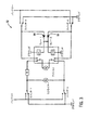
図2を参照して、制御回路26の例示的実施形態が、制御回路50として示されている。制御回路50は、4つのスイッチ、すなわちスイッチ1、スイッチ2、スイッチ3、及びスイッチ4を含む。制御回路50はさらに、リレー1、リレー2、及び抵抗Rを含む。抵抗Rは、1オームから3オームの間、好適には2オームの抵抗を有し、約50ワットに定格されるが、代替的には、他の抵抗及び電力特性を有してよい。シートバックモーター32(或いはリクライナーモーター)は、抵抗R及びシート基部モーター34(或いはクッションモーター)と並列に配置される。リレー1は、抵抗R及びスイッチ3の間で、シート基部モーター34の1つの端子をスイッチするよう構成される。リレー2は、スイッチ2及びスイッチ4の間でシート基部モーター34の第2の端子をスイッチするよう構成される。スイッチ1、2、3、及び4のそれぞれは、車両電源からモーター32、34及びリレー1,2まで、バッテリー或いはグラウンドのいずれかを選択するよう構成される。スイッチ1及び2は、シートバックボタン36に接続され、同時には駆動され得ない。スイッチ3及び4は、シート基部ボタン38に接続され、同時には駆動され得ない。リクライナーボタン36が前方に移動する場合(図1、矢印40)、スイッチ1は、バッテリーを、モーター32と抵抗Rとの間の端子に接続し、シートバック14を前方に駆動する。バッテリーからの入力電圧は、抵抗Rを介してシート基部モータ34に供給され、シートバック14の傾斜角度ごとに、約1.5ミリメーターのスピードで、シート基部モーター34を駆動する。こうして、抵抗Rは、モーター32に亘る第1の電圧、及びモーター34に亘る、より小さい第2の電圧を提供するよう構成される電圧分割ネットワークの一部をなす。これに応じて、モーター32は、通常のスピードで動作し、モーター34は、この通常のスピードから減速されたスピードで動作する。
With reference to FIG. 2, an exemplary embodiment of
シートバックボタン36が後方に移動する場合(図1、矢印40)、スイッチ2は、バッテリーからシートバックモーター32の他の端子に電力を供給し、シートバック14を後方に駆動する。スイッチ2はまた、バッテリー入力電圧を、リレー2、リレー1及び抵抗Rを介してシート基部モーター34に供給し、シートバック14の傾斜角度ごとに、シート基部12を1.5ミリメーターのスピードで前方に移動する。
When the seat back
シート基部ボタン38が後方に移動する場合(図1、矢印42)、スイッチ3は、バッテリー入力電圧を、リレー1のコイルに供給し、このコイルは、シート基部モーター34への入力を、抵抗Rからスイッチ3に切り替え、シート基部モーター34の他の端子を、リレー2のコイルを介して、スイッチ2からスイッチ4へと切り替える。車両入力電圧が、モーター34を介して直接(即ち、抵抗Rを介さず)供給されるため、モーター34は、入力電圧が抵抗Rを介して提供される場合より、より速い、通常のスピードで駆動される。シート基部モーター34は、シート基部12を後方に駆動し、シートバックモーター32は、駆動されず、これにより、シートバック14は移動しない。
When the
シート基部ボタン38が前方に移動する場合(図1、矢印42)、スイッチ4は、入力電圧を、バッテリーからリレー2及びリレー1のコイルを介して供給し、シート基部モーター34の端子をスイッチ3及び4に接続する。入力電圧は、スイッチ3を介してグラウンドに戻り、これにより、シート基部34を、前方に、より速い、通常スピードで駆動する。スイッチ1及び3が同時に作動された場合は、シートバックを前方に、及びシート基部12を後方に移動させるコマンドを示し、リレー1及び2は、作動され、モーター32及び34の双方は、フルスピードで作動されてユーザーコマンドを実行する。スイッチ1及び4が同時に作動された場合、この場合もやはりリレー1及び2は、双方のコマンドがフルスピードで実行されるよう作動される。同様に、スイッチ2及び3、又はスイッチ2及び4が作動されると(シートバック14を後方にシート基部12を後方に移動するユーザーコマンド、及びシートバック14を後方にシート基部12を前方に移動するユーザーコマンドにそれぞれ対応する)、入力電圧をバッテリーからモーター32及び34を介してグラウンドに供給する回路に抵抗Rが含まれないため、モーター32及び34の動作は、通常スピードで実行される。
When the
図3を参照して、本発明の代替的実施形態にかかる制御回路52の概略図が示される。制御回路52は、制御回路50と同様であるが、スイッチ3がダイオード54を介してリレー1のコイルに結合され、スイッチ4がダイオード56を介してリレー2のコイルに結合される点において相違する。ダイオード54及び56のアノードは、スイッチ3及び4にそれぞれ結合され、ダイオード54及び56のカソードは、相互に、及びリレー1及び2のコイルに結合される。リレー1及び2のコイルの反対端は、グラウンドに結合される。ダイオード54及び56は、モーター34からのターンオン及びターンオフ時の過渡的電圧異常(誘導キックとしても参照される)から、リレーコイルを保護する。
Referring to FIG. 3, a schematic diagram of a
図4を参照して、制御回路26のさらに例示的実施形態が、制御回路58として示される。本実施形態において、図2及び図3の実施形態におけるリレー1及び2は、2つの付加的スイッチであるスイッチ3´及び4´で置換される。スイッチ1,2、3、3´、4、及び4´のそれぞれは、本図に図示されており、本明細書の他の図において、停止或いはスリープ状態、非作動状態とも称される状態で図示される。シートバックボタン36が、図示されて矢印40を含み、この矢印は、ボタン36の前方移動はスイッチ1の作動に対応し、ボタン36の後方動作はスイッチ2の作動に対応することを示す。同様に、シート基部ボタン38は、矢印42に沿って図示され、この矢印は、ボタン38の後方移動がスイッチ3及び3´の作動に対応し、ボタン38の前方移動がスイッチ4及び4´に対応することを示す。
With reference to FIG. 4, a further exemplary embodiment of
本実施形態において、抵抗Rは、スイッチ1及びスイッチ3の間に結合される。スイッチ3は、選択的に、グラウンドとスイッチ4´の間に、スイッチ3の他の端子を結合する。 In this embodiment, resistor R is coupled between switch 1 and switch 3. Switch 3 selectively couples the other terminal of switch 3 between ground and switch 4 '.
スイッチ4´は、選択的に、スイッチ3をバッテリー或いはモーター34のいずれかに結合する。モーター34の他の端子は、スイッチ3´に結合される。スイッチ3´は、モーター34の他の端子を、選択的に、車両バッテリー或いはスイッチ4に結合する。スイッチ4は、スイッチ3´を、選択的にグラウンド或いはスイッチ2に結合する。図2及び図3の実施形態のように、リクライナーモーター32は、スイッチ1とスイッチ2との間に結合され、スイッチ1及びスイッチ2は、選択的にバッテリー或いはグラウンドをモーター32に結合し、モーター32を前方或いは後方方向に駆動する。
Switch 4 ′ optionally couples switch 3 to either the battery or the
動作中、スイッチ1及び2は、ボタン36に接続され、同時には作動し得ない。スイッチ3及び3´はともに接続され、ボタン38の後方移動によって、作動される。スイッチ4及び4´はともに接続され、ボタン38の前方移動によって作動される。ボタン36が前方に移動する場合、スイッチ1は、作動し、バッテリー入力電圧をモーター32を介して抵抗R、スイッチ3、スイッチ4´に供給する。このようにして、モーター34は減速スピードで、好適にはモーター32の1度の移動に対して1.5ミリメートルの速度で駆動される。
In operation, switches 1 and 2 are connected to
ボタン36が後方に移動する場合、スイッチ2は、作動し、バッテリー電源をモーター32を介してスイッチ1、グラウンドに結合し、バッテリー電源をスイッチ2を介してスイッチ4、スイッチ3´に、モーター34を介してスイッチ4´、スイッチ3に、抵抗Rを介してスイッチ1、グラウンドに供給する。このようにして、シートバック36は、後方に移動し、シート基部12は、減速スピードで前方に移動する。
When
ボタン38が前方に移動する場合、スイッチ4及び4´が作動し、ここで、入力電圧は、スイッチ4´からモーター34を介してスイッチ3´、スイッチ4、グラウンドに供給され、これにより、モーター34を前方に通常スピードで移動する。ボタン38が後方に移動する場合、スイッチ3及び3´が作動し、ここで、電源は、車両バッテリーからスイッチ3´へ、モーター34を介してスイッチ4´、スイッチ3、グラウンドへ供給され、これによりモーター34を通常スピードで後方に動作させる。ボタン36及び38がともに前方に移動する場合、モーター32はフルスピードで前方動作し、モーター34はフルスピードで前方動作する。ボタン36及び38が後方に移動するか又は前方及び後方の組み合わせで移動する場合、モーター32及び34は、同時に通常スピードで動作する。
When the
図5を参照して、制御回路26の他の例示的実施形態が、制御回路60として図示される。本実施形態において、図4の実施形態におけるスイッチ3、3´、及びスイッチ4、4´は、3−wayスイッチで置換され、ここで、スイッチ3は、モーター34の1つの端子を、バッテリー電源、グラウンド、或いは抵抗Rに結合する。同様に、スイッチ4は、モーター34の他の端子を、バッテリー電源、グランド、或いはスイッチ2とモーター32との間の端子に結合する。モーター32及び34は、1つの端子を抵抗R及びモーター32で共有して、並列に配置される。ボタン38のみが作動する場合、スイッチ3は、バッテリー電源を、モーター34に提供し、スイッチ4は、閉回路をグラウンドに提供する。ボタン38のみが前方に作動した場合、バッテリー電源は、スイッチ4を介してモーター34に提供され、スイッチ3は、グラウンドに閉回路を提供する。シートバックボタン36が、前方或いは後方に作動した場合、スイッチ3及び4は、停止状態となり、ここで、入力電圧は、抵抗Rのみを介してモーター34に供給され、これにより、ボタン38のみが作動した場合より低速スピードで、モーター34を動作させる。さらに、ボタン38がボタン36と同時に作動した場合、入力電圧は、抵抗Rを介さずに、独立してモーター32及び34に供給され、これにより、双方のモーターは、双方向に、そのフルの、通常スピードで動作する。
With reference to FIG. 5, another exemplary embodiment of
図2から図5の実施形態において、顕著には、抵抗Rは、シート基部モーター34に亘る第1の電圧と、シートバックモーター32に亘る第2の電圧とを供給するよう構成される電圧分割回路の一部を具備し、ここで、2つの電圧は相違する。この電圧の相違は、モーター34を、モーター32と異なるスピード、好適にはより低速スピードで駆動して、パワーグライド機構を提供するため使用され得る。また注目すべきことに、図2から図5の回路は、オープンループ制御を提供し、ここでモータ32及び34の位置に関して、フィードバックが提供されない。ある代替的実施形態によれば、フィードバックが提供されて、モーター32及び34の位置をさらに改善してもよい。
In the embodiment of FIGS. 2-5, notably, the resistor R is configured to provide a first voltage across the
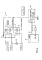
図6を参照して、制御回路26の代替的実施形態が、制御回路62として示される。本実施形態において、デジタルプロセッサ、好適にはマイクロプロセッサ64は、シート基部モーター34及び/又はシートバックモーター32(図示せず)に制御信号を供給する。本実施形態において、パルス幅変調制御信号は、マイクロプロセッサ出力66から、トランジスタ68に供給され、このトランジスタは、本例示的実施形態においては温度保護された電界効果トランジスタ(FET)であるが、代替的に他のトランジスタであってもよい。トランジスタ68は、Infineon Technologies,Munich,ドイツにより製造されたBTS282Zトランジスタである。温度保護は、長期使用或いは連続高電流使用による異常高温から、FETを保護する利点を提供する。トランジスタ68のソースは、グラウンドに結合され、トランジスタ68のドレインは複数のリレー70、72のそれぞれの1つの入力に結合される。リレー70及び72は、出力74及び出力76として示されるマイクロプロセッサ64からのデジタル出力により作動する。シート基部ボタン38(図1)が前方或いは後方に移動する場合、デジタル信号が出力74及び出力76にそれぞれ供給され、リレー70及び72を駆動して、電源を車両バッテリー電源からモーター34に供給する。シートバックボタン36のみが前方及び後方に作動する場合、出力74及び76は作動せず、調整可能な制御信号は、マイクロプロセッサ64から出力66及びトランジスタ68を介して、モーター34に、リレー70及び72が作動する場合に供給されるのより少ない電力量を供給する。好適には、制御回路64は、シートバックボタン36が作動する場合、シート基部ボタン38が作動する場合より低速スピードでモーター34を制御するよう構成される。さらに、速度比は、シートバック14が1度移動するごとに、シート基部12が好適には1.5ミリメーター移動する比率である。トランジスタ68をバッテリーの電圧スパイクから保護するため、ダイオード78が、車両電源及びトランジスタ68の間に提供される。
With reference to FIG. 6, an alternative embodiment of
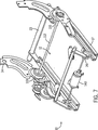
図7を参照して、本発明の代替的な例示的実施形態に係る車両シートの手動による実施形態が示され、この実施形態は、シート基部12(図示せず)と、シートバック14(部分的フレームとして図示される)と、及びシート10の前後移動を支持するシートトラック17とを有するシート10を含む。ここにおいて、用語“手動”は、電動モータを使用しない運動、メカニズム等を参照するため使用される。また、用語“手動による作動”とは、手で移動、調整、或いは動作される運動、メカニズム等を参照するため使用される。
Referring to FIG. 7, a manual embodiment of a vehicle seat according to an alternative exemplary embodiment of the present invention is shown, which includes a seat base 12 (not shown) and a seat back 14 (partial). And a
図7において、シート10はさらに、バー112に相互接続される第1及び第2のリクライナー機構110を含む。このリクライナー機構110は、シート基部12に対するシートバック14の位置の選択的調整を提供する。このリクライナー機構は、好適には、あらゆる公知の或いは適切なタイプのリクライナー機構を使用して製造されるが、有利には、米国特許No.6,390,557に従って製造されてよく、その開示は、参照により本開示の一部をなす。リクライナー機構110は、好適には、例えば図8に示されるように、ハンドル114を用いて作動される。このハンドル114は、リクライナー機構110の1つに接続され、バー部材112は、1つのリクライナー機構110の作動を、他のリクライナー機構110に伝達する。
In FIG. 7, the
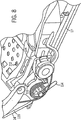
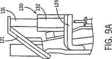
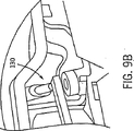
従って、リクライナー機構110は、シートバック14のフレーム部材と、シート基部12のフレーム部材との間に位置する。図8及び図9を参照して、リクライナーブラケット120及びシート基部ブラケット124が図示される。シート基部ブラケット124に対して、シートバック14のリクライナーブラケット120の位置を決定するため、センサー130が提供される。ある実施形態において、センサー130は、プランジャ型のポテンショメータであり、延長部ブラケット125によって、シート基部ブラケット124上で支持される。センサー130は、シートベース12に対するシートバック14の移動を正確に検出する。センサー130は、シートバック14の移動により作動し、ここで延長部ラケット121がリクライナーブラケットに接続されて、センサー130のプランジャ131に接触し、これによりプランジャ131は、センサー130の基部132に対して、リクライナー機構110によって調整されるシートバック14の角度回転に比例する量だけ移動する。代替的に、センサー130は、ホール効果センサーであってよい。ポテンショメータ130に替えて他の設計のセンサーが使用され得、これにより、そのセンサーがシートバック14のリクライン位置或いはリクライン速度を正確に示す限り、あらゆる公知或いは適切な設計のセンサー130が使用され得ることが、理解されるべきである。
Accordingly, the
理解されるとおり、図7から図9に示される実施形態のシート10のリクライナー機構110は、手動により作動されて、シートバック14の位置を調整する。しかしながら、シート基部12は、シートトラック17に沿って、シート10を移動するため、電動モーター140を使用して移動するよう設計される。さらに、上記したとおり、電動の制御回路26に対し、シートバック14が1度移動するごとに、約1ミリメーターから約4ミリメーターの間、好適には、約1.5ミリメーターから約3ミリメーターの間、シート基部12が移動する特定の比率を提供することは有利である。こうして、センサー130により検出されるシートバック14の1度の回転ごとに、シート基部12は結果的に調整される。これは、図10及び図11に示される制御回路160及び170を使用して達成され得る。制御回路160及び170の特徴及び原理は、相互に組み合わせて、単独で、又はあらゆる好適な構成において、使用され得る。
As will be appreciated, the
ある実施形態において、センサー130は、特定の値を有するセンサー130の出力として提供されるシートバック14の回転角度を検出する。制御回路160或いは170は、センサー130から特定の値を検出し、シートバック14が1度回転するごとに、約1ミリメーターから約4ミリメーターである、シート基部12を移動する所望の比率に基づいて、シート基部12が移動すべき量を決定する。シート基部12は、閉ループフィードバック制御を用いて、所望の位置に移動してよい。例えば、いったんシートバック14が、その新たな位置が知られた位置まで移動すると、その新たな位置は、シート基部12の所望の位置を決定するための入力として使用され得る。この構成において、シート基部12は、シート基部12の位置を測定するセンサーを含む。こうして、シート基部12は、シート基部がその所望の位置に到達するまで、閉ループフィードバック制御を使用して移動される。
In one embodiment, the
例示的実施形態において、制御回路160及び170は、シートバック14が移動を停止するまで、シート基部12の移動を遅延させる。ある実施形態において、これは、センサー130を使用して、シートバック14がいつ移動を停止するかをモニターすることで達成され得る。典型的には、シート基部12が移動する前の遅延は、約1秒だが、約0.5秒から約3秒までの間のいずれかであってよく、或いは約0.5秒から約2秒までの間であってよい。
In the exemplary embodiment,
他の実施形態において、シート基部12は、適切な期間、単純に電動モーター140をオンすることによって、再配置される。この構成において、シート基部12の位置は、測定されない。むしろ、電動モーター140のオン時間は、所定の関係の関数となる。また、車両シートは、典型的には、シート基部12が水平でないよう取り付けられるため、電動モーター140は、同じ距離を移動するため、他の方向よりもある方向でより長い時間、オンする必要があり得る。例えば、自動車の車両シートは、シート基部12が約6度前方傾斜するよう取り付けられ得る。この状況において、シート基部12は、後方に移動する場合、重力によって補助され、前方に移動する場合、重力によって妨げられる。これにより、シート基部12は、前方に移動するより速いスピードで、後方に移動する。説明したとおり、重力の効果は、シート基部12が前方或いは後方のいずれに移動するかによって、電動モーター140のオン時間を変動することにより、考慮され得る。例えば、電動モーター140は、シートバック14が3度リクラインされた場合(シート基部12が前方に移動し、重力により妨げられる場合)、シートバック14が3度インクラインされた場合(シート基部が後方に移動し、重力により援助される場合)より、長い時間、オンされ得る。電動モーター140のオン時間の相違は、車両シート及びドライバーそれぞれの特性に特有である。しかしながら、それぞれのドライバーの特性は、平均及び他の統計的技術を用いて、近似され得る。
In other embodiments, the
図10に示される制御回路160は、以下さらに詳細に説明される。制御回路160は、マイクロプロセッサ220と、リレー224と、電圧レギュレータ226と、及びポリスイッチ228とを含む。入力電圧は、電源230からダイオード250及び電圧レギュレータ226を介して、マイクロプロセッサ220及びセンサー130に流れる。ダイオード250は、逆極性保護装置として動作し、これにより、回路の素子の1つの極性が逆転しても、素子に損傷を与えない。電圧レギュレータ226は、入力電圧を12ボルトから5ボルトまで低減する。電圧レギュレータ226はまた、突然の電圧低下を検知し、マイクロプロセッサ22に、シャットダウンを指示する信号を送出するよう機能する。このようにして、電圧レギュレータ226は、マイクロプロセッサ220が、必要なシャットダウン手順を実行することなく、突然シャットオフするのを防止する。
The
図10に示されるマイクロプロセッサ220は、マスクメモリー型であり、1キロバイトのランダム・アクセス・メモリ及び8ビットの中央演算処理ユニットを有する。マイクロプロセッサ220は、STMicroelectronics,1060 East Brokaw Road,San Jose,CA95131から入手可能なST6マイクロプロセッサ、或いは、Microchip Technology Inc.,2355 West Chandler Blvd.,Chandler,AZ85224から入手可能なPICマイクロプロセッサであってよい。しかしながら、あらゆるマイクロプロセッサが制御回路160中で使用され得ることが理解されるべきである。
The
制御回路160は、入力232を具備し、この入力は、センサー130と、ユーザーにより作動され得、シート基部12のみを移動する(即ち、シートバック14が移動することなくシート基部12が移動すること)スイッチとを含む。入力信号は、入力232からマイクロプロセッサ220に、マイクロプロセッサ220を電圧及び電流変動に損傷を与えられることから保護する機能を果たす1つ又は複数のバッファ234を経由して、伝達される。マイクロプロセッサ220は、入力信号を、リレー224を介して電動モーター140を制御するため使用する。センサー130は、ポテンショメータ、或いは例えばホール効果センサー等のあらゆる他の適切なタイプのセンサーであってよい。
The
マイクロプロセッサ220は、リレー224を使用して、電動モーター140の方向を制御し、シート基部12を前方或いは後方に移動する。信号が、マイクロプロセッサ220から、増幅器或いは電流ブースター236を介してリレー224に供給され、これら増幅器或いはブースターは、信号強度を増加させるよう作用する。リレー224は、スイッチ238を動作させて、電動モーター140の極性を制御する。リード240は、電動モーター140を電源230及び高電流グラウンド242に接続する。スイッチ238の構成によって、リード240の1つは、ハイサイドであり、他のリード240はロウサイドとなる。制御回路160において、電動モーター140は、専用の電源及びグラウンド接続を有し(即ち、高電流グラウンド242は、電動モーター140用のグラウンドを参照し、低電流或いはロジックグラウンド248は、マイクロプロセッサ220用のグラウンドとなる)、過剰ノイズが、制御回路160の他のコンポーネントの動作に干渉するのを防止する。電動モーター140は、ポリスイッチ228を介して、電源230及び高電流グラウンド242に結合され、このポリスイッチは、リセット可能なヒューズとして機能する。こうして、電動モーター140が過剰な電流を引き込んだ場合、ポリスイッチは、回路をオープンにして電動モーター140が損傷するのを防止する。マイクロプロセッサ220は、線244で示されるように、電動モーター140に関連するステータス信号を受信する。このステータス信号は、バッファ234と同様に機能する1つ又は複数のバッファ246を介して、伝播する。
The
制御回路160の一部として、キャパシタ252及び過渡サプレッサ254もまた含まれる。キャパシタ252は、制御回路160のそれぞれの部分に所望の定電圧を維持することの補助のため、電荷を蓄えるのみならず、制御回路160からノイズをフィルター処理する。過渡サプレッサ254は、制御回路160で発生し得る電圧スパイクを捕捉するため用いられる。
As part of the
図11に示されるとおり、制御回路170は、モジュール210を含み、このモジュールは、ポテンショメータ212及びスイッチ214から信号を受信し、その結果その信号に基づいてシート基部モーター216を制御するよう構成される。ポテンショメータ212は、シートバック14が移動したか否かを判定し、移動を判定した場合には、シートバック14の新たな位置を判定する。ある実施形態において、ポテンショメータ212は、マイクロスイッチと組み合わされて、ハンドル114(図8)の移動をセンスする。本実施形態において、制御回路170は、ウェイクアップ機能を含み、これによりシートバック14がいかなる調整もされることなく所定時間が経過した後、制御回路170は、スリープモードに入る。ウェイクアップモードにおいて、制御回路170は、ポテンショメータ212の位置を連続的に決定する。スリープモードにおいて、制御回路170は、ポテンショメータ212の位置を決定しない。マイクロスイッチは、シートバック14が移動したか否かを決定し、これに応じて、制御回路170に信号を送出してスリープモードを終了し、ポテンショメータ212の位置の読み取りを開始する。他の実施形態において、例えばホール効果センサー等の装置は、ポテンショメータ212及びマイクロスイッチに替えて使用され得る。この実施形態において、ホール効果センサーは、シートバック14が移動した場合にのみ信号を送出するため、マイクロスイッチは、必要でない。この情報は、その結果シート基部14を調整するモジュール210に入力される。スイッチ214は、シートバック14とは独立して、シート基部モーター216を移動するため使用される。この特性は、ユーザーがシート基部のみの調整を望む場合に有用である。
As shown in FIG. 11, the
制御回路170に関連して説明されたウェイクアップ機能は、シートバック14の移動に応じてシート基部12を移動するために使用され得る他の制御回路同様、制御回路160に適用され得る。一般的に、ウェイクアップ機能は、シートバック14の位置に何ら変化がない間は、制御回路160及び170の不必要な電力消費を防止し、これにより、所定の移動比率を維持するためにシート基部12を移動する必要がない。
The wake-up function described in connection with the
図面及び上記において説明された例示的実施形態は、現在において好適であるが、これらの実施形態は例示のみとして提示されていることが理解されるべきである。他の実施形態もまた、使用され得る。本発明は、特定の実施形態に限定されるものではなく、クレームの範囲及び要旨の範囲内にある、多様な変形、組み合わせ、及び配列にまで及ぶ。 Although the drawings and the exemplary embodiments described above are presently preferred, it should be understood that these embodiments are presented by way of example only. Other embodiments can also be used. The invention is not limited to specific embodiments, but extends to various modifications, combinations, and arrangements that are within the scope and spirit of the claims.
Claims (17)
シート基部を前方及び後方に移動するように構成されるシート基部モータと;
シートバックの傾斜角度を調整するように構成される手動リクライナー機構と;および
前記傾斜角度の変更に応じて、前記シート基部を前方或いは後方に移動するよう構成される制御回路とを具備し、
前記制御回路は前記シート基部モータを制御し、前記シートバックの傾斜角度に比例する距離まで前記シート基部を移動する
ことを特徴とする車両シート用の制御システム。A control system for a vehicle seat,
A seat base motor configured to move the seat base forward and backward;
Manual recliner mechanism and configured to adjust the inclination angle of the seat back; depending on and change of the inclination angle, comprises a configured control circuit to move the seat base forward or backward,
The control system for a vehicle seat, wherein the control circuit controls the seat base motor and moves the seat base to a distance proportional to an inclination angle of the seat back .
ことを特徴とする請求項1に記載の車両シート用の制御システム。The control circuit is configured to move the sheet base forward according to a reclining line of the seat back and to move the sheet base backward according to an ink line of the seat back. The control system for vehicle seats of Claim 1.
前記シートバックの位置を測定するセンサを具備し、
前記センサにより検出された前記シートバックの位置に応じた傾斜角度に比例する距離まで前記シート基部を移動する
ことを特徴とする請求項1に記載の車両シート用の制御システム。The control system further includes:
Comprising a sensor for measuring the position of the seat back ;
2. The vehicle seat control system according to claim 1, wherein the seat base is moved to a distance proportional to an inclination angle corresponding to a position of the seat back detected by the sensor .
ことを特徴とする請求項4に記載の車両シート用の制御システム。The control system for a vehicle seat according to claim 4, wherein the sensor is a potentiometer.
シート基部を前方及び後方に移動するよう構成されるシート基部モータと;
シートバックの傾斜角度を調整するよう構成される手動リクライナー機構と;及び
前記シート基部モータを制御し、前記シートバックの傾斜角度に比例する距離まで前記シート基部を移動するよう構成される制御回路とを具備し、
前記シートバックの傾斜角度約1度に対して約1mmから約3mmの間の比率で前記シート基部を前方又は後方に移動するように構成され、前記シートバックが前方に傾斜角度約1度でインクラインされたときには前記シート基部を後方に約1mmから約3mmの間の比率で移動し、前記シートバックが後方に傾斜角度約1度でリクラインされたときには前記シート基部を前方に約1mmから約3mmの間の比率で移動する
ことを特徴とする車両シート用の制御システム。A control system for a vehicle seat,
A seat base motor configured to move the seat base forward and backward;
A manual recliner mechanism configured to adjust a seat back tilt angle; and a control circuit configured to control the seat base motor and move the seat base to a distance proportional to the seat back tilt angle; Comprising
The seat base is configured to move forward or backward at a ratio of about 1 mm to about 3 mm with respect to an inclination angle of the seat back of about 1 degree, and the sheet back is moved forward at an inclination angle of about 1 degree. When seated, the seat base moves backward at a ratio of about 1 mm to about 3 mm. When the seat back is reclined backward at an inclination angle of about 1 degree, the seat base moves forward from about 1 mm to about 3 mm. Control system for vehicle seats , characterized in that it moves at a ratio between
トラックと;
前記トラックに結合されるシート基部と;
前記シート基部を前方及び後方に移動するよう構成されるシート基部モータと;
前記トラックに枢支結合されるシートバックと;
前記トラックに対して、前記シートバックを枢支回動するよう構成される手動リクライナー機構と;
前記シート基部の移動用のオペレータコマンドを受信するよう構成されるシート基部入力装置と;及び
前記シート基部入力装置からの前記オペレータコマンドを受信して前記シート基部モータを制御するよう構成される制御回路とを具備し、
前記制御回路は前記シート基部モータを制御し、前記シートバックの傾斜角度に比例する距離まで前記シート基部を移動するよう構成され;及び
前記制御回路は前記シート基部入力装置からのコマンド受信に応答して、前記シート基部モータを制御し、前記シート基部のみを移動するよう構成される
ことを特徴とする車両シート。A vehicle seat having a control system,
With track;
A sheet base coupled to the track;
A seat base motor configured to move the seat base forward and backward;
A seat back pivotally coupled to the track;
A manual recliner mechanism configured to pivotally pivot the seat back relative to the track;
And the configured control circuit to receive the operator commands to control the sheet base motor from the seat base input device; sheet base input device and configured to receive operator commands for movement of the seat base And
The control circuit is configured to control the seat base motor and move the seat base to a distance proportional to the seat back tilt angle ; and the control circuit is responsive to command reception from the seat base input device. The vehicle seat is configured to control the seat base motor and move only the seat base.
前記シートバックの位置を測定するセンサーを具備し、
前記制御回路は、前記センサにより検出された前記シートバックの位置に応じた傾斜角度に比例する距離まで前記シート基部を移動する
ことを特徴とする請求項8に記載の車両シート。The vehicle seat further includes:
Comprising a sensor for measuring the position of the seat back;
The vehicle seat according to claim 8 , wherein the control circuit moves the seat base to a distance proportional to an inclination angle corresponding to a position of the seat back detected by the sensor .
ことを特徴とする請求項10に記載の車両シート。The vehicle seat according to claim 10 , wherein the sensor is a potentiometer.
ことを特徴とする請求項8に記載の車両シート。The control circuit moves the seat base substantially forward according to the rear pivoting rotation of the seat back, and moves the seat base substantially backward according to the forward pivoting rotation of the seat back. The vehicle seat according to claim 8 .
ことを特徴とする請求項8に記載の車両シート。The vehicle seat according to claim 8 , wherein the manual recliner mechanism is driven by a handle.
ことを特徴とする請求項8に記載の車両シート。The vehicle seat according to claim 8 , wherein the control circuit includes a microprocessor.
シート基部を前方及び後方に移動するよう構成されるシート基部モータと;
シートバックの傾斜角度を調整するよう構成される手動リクライナー機構と;及び
前記シートバックのインクラインに応じて、前記シート基部を後方に移動するよう構成される制御回路とを具備し、
前記制御回路は前記シート基部モータを制御し、前記シートバックのインクラインの傾斜角度に比例する距離まで前記シート基部を後方に移動する
ことを特徴とする車両シート用の制御システム。A control system for a vehicle seat,
A seat base motor configured to move the seat base forward and backward;
Manual recliner mechanism and configured to adjust the inclination angle of the seat back; in response to and Incline of the seat back, comprising a configured control circuit to move the seat base backward,
The control system for a vehicle seat, wherein the control circuit controls the seat base motor and moves the seat base backward to a distance proportional to an inclination angle of an ink line of the seat back .
ことを特徴とする請求項15に記載の車両シート用の制御システム。The control system, in response to said about 1 degree per the inclination of the seat back, according to claim 15, characterized in that configured to move between about 3mm to about 1mm the sheet base to the rear Control system for vehicle seats.
前記シートバックの位置を測定するセンサをさらに具備する
ことを特徴とする請求項15に記載の車両シート用の制御システム。The control system further includes:
The vehicle seat control system according to claim 15 , further comprising a sensor that measures a position of the seat back.
Applications Claiming Priority (2)
| Application Number | Priority Date | Filing Date | Title |
|---|---|---|---|
| US43780403P | 2003-01-03 | 2003-01-03 | |
| PCT/US2003/019174 WO2004062961A1 (en) | 2003-01-03 | 2003-06-18 | Automotive seat with control system |
Publications (2)
| Publication Number | Publication Date |
|---|---|
| JP2006512169A JP2006512169A (en) | 2006-04-13 |
| JP4105166B2 true JP4105166B2 (en) | 2008-06-25 |
Family
ID=32713231
Family Applications (1)
| Application Number | Title | Priority Date | Filing Date |
|---|---|---|---|
| JP2004566416A Expired - Fee Related JP4105166B2 (en) | 2003-01-03 | 2003-06-18 | Car seat with control system |
Country Status (8)
| Country | Link |
|---|---|
| US (1) | US20060208549A1 (en) |
| EP (1) | EP1587706B1 (en) |
| JP (1) | JP4105166B2 (en) |
| CN (1) | CN100447014C (en) |
| AT (1) | ATE470593T1 (en) |
| AU (1) | AU2003243625A1 (en) |
| DE (1) | DE60332963D1 (en) |
| WO (1) | WO2004062961A1 (en) |
Families Citing this family (47)
| Publication number | Priority date | Publication date | Assignee | Title |
|---|---|---|---|---|
| WO2003068557A1 (en) | 2002-02-12 | 2003-08-21 | Johnson Controls Technology Company | Automotive seat with active back |
| US7239096B2 (en) | 2002-02-12 | 2007-07-03 | Johnson Controls Technology Company | Vehicle seat having an electronic control system |
| JP4804185B2 (en) * | 2006-03-24 | 2011-11-02 | 株式会社オーテックジャパン | Switch for raising and lowering the vehicle seat speed |
| US7823967B2 (en) * | 2007-03-26 | 2010-11-02 | Emteq, Inc. | Heater system for an aircraft seat |
| JP5418827B2 (en) * | 2009-08-21 | 2014-02-19 | アイシン精機株式会社 | Seat control mechanism |
| US8266743B2 (en) * | 2010-08-23 | 2012-09-18 | Midmark Corporation | Examination table with motion tracking |
| JP5655574B2 (en) * | 2011-01-07 | 2015-01-21 | アイシン精機株式会社 | Vehicle seat reclining device |
| DE102012007978A1 (en) * | 2012-04-20 | 2013-10-24 | GM Global Technology Operations LLC (n. d. Gesetzen des Staates Delaware) | Vehicle seat for a motor vehicle |
| US8807650B2 (en) | 2012-04-26 | 2014-08-19 | Barbara ASCHER | Infant to adult adjustable car seat |
| DE102012008822A1 (en) | 2012-05-07 | 2013-11-07 | GM Global Technology Operations LLC (n.d. Ges. d. Staates Delaware) | Adjustment device, motor vehicle seat, motor vehicle and method for this purpose |
| US9333880B2 (en) * | 2013-03-15 | 2016-05-10 | Lear Corporation | System and method for controlling vehicle seat movement |
| US20140316660A1 (en) * | 2013-04-18 | 2014-10-23 | Ford Global Technologies, Llc | Seat-integrated occupant presence detector |
| US9499072B2 (en) | 2014-02-17 | 2016-11-22 | Lear Corporation | Seat cushion length extender with sensor |
| EP3126242B1 (en) * | 2014-03-31 | 2018-08-15 | B/E Aerospace, Inc. | Aircraft seat with electronically-actuated mechanical cable release for locking gas spring and method |
| US9610862B2 (en) * | 2014-10-14 | 2017-04-04 | Faurecia Automotive Seating, Llc | Seat position sensing and adjustment |
| CN104601059A (en) * | 2015-01-16 | 2015-05-06 | 信阳师范学院 | Direct-current motor controller and method |
| FR3064557B1 (en) * | 2017-04-04 | 2021-01-29 | Zodiac Actuation Systems | SEAT ESPECIALLY FOR PASSENGER TRANSPORT VEHICLES |
| US10926667B2 (en) | 2018-05-04 | 2021-02-23 | Lear Corporation | Track assembly |
| US11040638B2 (en) | 2018-05-04 | 2021-06-22 | Lear Corporation | Track assembly |
| US11040639B2 (en) | 2018-05-04 | 2021-06-22 | Lear Corporation | Track assembly |
| US11358497B2 (en) | 2018-05-04 | 2022-06-14 | Lear Corporation | Track system having a rolling member |
| US10562414B2 (en) | 2018-05-04 | 2020-02-18 | Lear Corporation | Track assembly |
| US10906431B2 (en) | 2018-05-04 | 2021-02-02 | Lear Corporation | Track assembly |
| US10882420B2 (en) | 2019-03-08 | 2021-01-05 | Lear Corporation | Track assembly |
| US10850649B2 (en) * | 2018-05-24 | 2020-12-01 | Honda Motor Co., Ltd. | Vehicle seat controller |
| US11225201B2 (en) | 2018-12-10 | 2022-01-18 | Lear Corporation | Track assembly |
| US11440482B2 (en) | 2018-12-10 | 2022-09-13 | Lear Corporation | Track assembly |
| US11613220B2 (en) | 2018-12-17 | 2023-03-28 | Lear Corporation | Electrical assembly |
| US11117538B2 (en) | 2018-12-17 | 2021-09-14 | Lear Corporation | Electrical assembly |
| US10855037B2 (en) | 2018-12-17 | 2020-12-01 | Lear Corporation | Support assembly with a support member and a track assembly |
| US10950977B2 (en) | 2018-12-18 | 2021-03-16 | Lear Corporation | Track assembly for a vehicle component |
| US11161430B2 (en) * | 2019-02-07 | 2021-11-02 | Volvo Car Corporation | Vehicle occupant posture detection |
| US20200262367A1 (en) * | 2019-02-20 | 2020-08-20 | Lear Corporation | Electrical assembly |
| US11040653B2 (en) | 2019-02-25 | 2021-06-22 | Lear Corporation | Track assembly |
| US11299075B2 (en) * | 2019-03-06 | 2022-04-12 | Lear Corporation | Electrical assembly |
| US11807142B2 (en) | 2019-03-06 | 2023-11-07 | Lear Corporation | Electrical track assembly |
| US11323114B2 (en) | 2019-10-04 | 2022-05-03 | Lear Corporation | Electrical system |
| US11463083B2 (en) | 2019-10-04 | 2022-10-04 | Lear Corporation | Electrical system |
| US11634101B2 (en) | 2019-10-04 | 2023-04-25 | Lear Corporation | Removable component system |
| KR102286924B1 (en) | 2019-11-13 | 2021-08-06 | 현대자동차주식회사 | Automatic return apparatus for seat back of seat in vehicle and method for returning of the seat back of seat in vehicle |
| CN113043920B (en) * | 2019-12-27 | 2022-08-30 | 耀鸿(嘉兴)电子科技有限公司 | Electric chair system for vehicle and control method |
| US20210261022A1 (en) | 2020-02-21 | 2021-08-26 | Lear Corporation | Track system with a support member |
| DE102020107243B4 (en) * | 2020-03-17 | 2024-02-08 | Ciar S.P.A. | Sitting and lying furniture and method for adjusting a sitting and lying furniture |
| DE102020113982A1 (en) * | 2020-05-25 | 2021-11-25 | Faurecia Autositze Gmbh | MOTOR VEHICLE SEAT |
| US11505141B2 (en) | 2020-10-23 | 2022-11-22 | Lear Corporation | Electrical system with track assembly and support assembly |
| DE102022120657A1 (en) | 2022-08-16 | 2024-02-22 | Faurecia Autositze Gmbh | Vehicle seat with Easy Entry adjustment |
| US20240109462A1 (en) * | 2022-09-28 | 2024-04-04 | GM Global Technology Operations LLC | Integrated accessibility storage system |
Family Cites Families (41)
| Publication number | Priority date | Publication date | Assignee | Title |
|---|---|---|---|---|
| US2823949A (en) * | 1953-12-21 | 1958-02-18 | American Metal Prod | Adjusting means for the front seat of an automotive vehicle |
| DE3137150A1 (en) * | 1981-09-18 | 1983-04-07 | Robert Bosch Gmbh, 7000 Stuttgart | DEVICE FOR POSITIONING AT LEAST TWO ACTUATORS FOR MOTOR VEHICLE SEATS |
| DE3137151A1 (en) * | 1981-09-18 | 1983-04-07 | Robert Bosch Gmbh, 7000 Stuttgart | DEVICE FOR POSITIONING AT LEAST ONE ADJUSTING DEVICE FOR MOTOR VEHICLE SEATS |
| JPS5876336A (en) * | 1981-10-29 | 1983-05-09 | Aisin Seiki Co Ltd | Vehicle seat |
| JPS61157040U (en) * | 1985-03-23 | 1986-09-29 | ||
| DE3676388D1 (en) * | 1985-08-13 | 1991-02-07 | Aisin Seiki | DEVICE FOR CONTROLLING THE POSITION OF A DEVICE OF A VEHICLE. |
| DE3532608A1 (en) * | 1985-09-12 | 1987-03-19 | Grammer Sitzsysteme Gmbh | SEAT WITH AN ADJUSTABLE SEAT ELEMENT |
| JPH0761782B2 (en) * | 1986-12-04 | 1995-07-05 | アイシン精機株式会社 | Posture control system for vehicle seat |
| DE3910778C2 (en) * | 1989-04-04 | 1996-10-17 | Daimler Benz Ag | Method for controlling at least two adjusting devices of a motor vehicle seat, in particular associated with the longitudinal movement of the seat and the movement of the backrest inclination |
| US5253138A (en) * | 1989-07-04 | 1993-10-12 | Ets Cousin Freres | Simplified supplying system of the position identification potentiometers of electronic memory mechanisms of a motor for setting automobile vehicle seats and the like |
| AT394829B (en) * | 1989-08-04 | 1992-06-25 | Schuster Wilhelm | BACKREST FOR A VEHICLE SEAT, WITH AN ADJUSTABLE LUMBAR REST |
| JPH0439164A (en) * | 1990-06-04 | 1992-02-10 | Jidosha Denki Kogyo Co Ltd | Automatic driving position device |
| FR2664544B1 (en) * | 1990-07-12 | 1993-12-17 | Faure Automobile Bertrand | CENTRALIZED CONTROL BLOCK FOR VEHICLE SEAT. |
| JPH04201745A (en) * | 1990-11-30 | 1992-07-22 | Oki Electric Ind Co Ltd | Power seat for automobile |
| US5249839A (en) * | 1991-11-12 | 1993-10-05 | Steelcase Inc. | Split back chair |
| US5748473A (en) * | 1992-05-05 | 1998-05-05 | Automotive Technologies International, Inc. | Automatic vehicle seat adjuster |
| US6088640A (en) * | 1997-12-17 | 2000-07-11 | Automotive Technologies International, Inc. | Apparatus for determining the location of a head of an occupant in the presence of objects that obscure the head |
| FR2706826B1 (en) * | 1993-06-24 | 1995-08-25 | Bfa | |
| DE4339113C2 (en) * | 1993-11-16 | 1996-09-05 | Daimler Benz Ag | Seat occupancy detection device in a motor vehicle |
| FR2716649B1 (en) * | 1994-02-25 | 1996-05-31 | Faure France Bertrand | Longitudinal positioning device for a vehicle seat. |
| US5636898A (en) * | 1994-04-15 | 1997-06-10 | Burns Aerospace Corporation | Seat with recline linkage |
| US5497326A (en) * | 1994-08-03 | 1996-03-05 | The Cherry Corporation | Intelligent commutation pulse detection system to control electric D.C. motors used with automobile accessories |
| US5651587A (en) * | 1995-06-09 | 1997-07-29 | P.L. Porter Co. | Vehicle seat and system for controlling the same |
| FR2737164B1 (en) * | 1995-07-25 | 1997-11-28 | Cesa | ASSEMBLY FOR ADJUSTING THE POSITION OF AT LEAST TWO ORGANS OF A MOTOR VEHICLE |
| US6195603B1 (en) * | 1995-08-11 | 2001-02-27 | Lear Corporation | Multiple speed vehicle seat memory control apparatus |
| US5864105A (en) * | 1996-12-30 | 1999-01-26 | Trw Inc. | Method and apparatus for controlling an adjustable device |
| US6055473A (en) * | 1997-02-19 | 2000-04-25 | General Motors Corporation | Adaptive seating system |
| DE19734508C2 (en) * | 1997-08-08 | 2001-05-17 | Siemens Ag | Control device for a passenger protection device of a motor vehicle |
| US6157372A (en) * | 1997-08-27 | 2000-12-05 | Trw Inc. | Method and apparatus for controlling a plurality of controllable devices |
| JP3702606B2 (en) * | 1997-09-29 | 2005-10-05 | アイシン精機株式会社 | Vehicle seat structure |
| US6220661B1 (en) * | 1999-04-19 | 2001-04-24 | Steelcase Development Inc. | Chair back and method of assembly |
| US5871258A (en) * | 1997-10-24 | 1999-02-16 | Steelcase Inc. | Chair with novel seat construction |
| US6030043A (en) * | 1997-12-18 | 2000-02-29 | Bertrand Faure Sitztechnik Gmbh & Co. Kg | Motor vehicle seat, in particular back seat |
| JP4265024B2 (en) | 1998-06-22 | 2009-05-20 | トヨタ紡織株式会社 | Reclining device |
| CN2351321Y (en) * | 1998-09-01 | 1999-12-01 | 姚巨波 | Multi-function electric vehicle seat |
| US6079785A (en) * | 1999-01-12 | 2000-06-27 | Steelcase Development Inc. | Chair having adjustable lumbar support |
| US6179384B1 (en) * | 1999-04-21 | 2001-01-30 | Steelcase Development Inc. | Force adjusting device |
| DE19939183C1 (en) * | 1999-08-20 | 2000-10-05 | Daimler Chrysler Ag | Electric adjustment device for automobile front passenger seat has two independent switches coupled to control for forwards movement of front passenger seat to provide easy-entry function for rear passenger |
| CN2433118Y (en) * | 2000-05-30 | 2001-06-06 | 朱丰 | Seat of electric vehicle |
| US6677720B2 (en) * | 2001-06-08 | 2004-01-13 | Dura Global Technologies, Inc. | Control system for vehicle seat |
| US7239096B2 (en) * | 2002-02-12 | 2007-07-03 | Johnson Controls Technology Company | Vehicle seat having an electronic control system |
-
2003
- 2003-06-18 DE DE60332963T patent/DE60332963D1/en not_active Expired - Lifetime
- 2003-06-18 AT AT03815170T patent/ATE470593T1/en not_active IP Right Cessation
- 2003-06-18 CN CNB038259621A patent/CN100447014C/en not_active Expired - Fee Related
- 2003-06-18 EP EP03815170A patent/EP1587706B1/en not_active Expired - Lifetime
- 2003-06-18 WO PCT/US2003/019174 patent/WO2004062961A1/en active Application Filing
- 2003-06-18 AU AU2003243625A patent/AU2003243625A1/en not_active Abandoned
- 2003-06-18 JP JP2004566416A patent/JP4105166B2/en not_active Expired - Fee Related
- 2003-06-18 US US10/541,370 patent/US20060208549A1/en not_active Abandoned
Also Published As
| Publication number | Publication date |
|---|---|
| CN1741917A (en) | 2006-03-01 |
| EP1587706A1 (en) | 2005-10-26 |
| CN100447014C (en) | 2008-12-31 |
| DE60332963D1 (en) | 2010-07-22 |
| ATE470593T1 (en) | 2010-06-15 |
| WO2004062961A1 (en) | 2004-07-29 |
| US20060208549A1 (en) | 2006-09-21 |
| AU2003243625A1 (en) | 2004-08-10 |
| JP2006512169A (en) | 2006-04-13 |
| EP1587706B1 (en) | 2010-06-09 |
Similar Documents
| Publication | Publication Date | Title |
|---|---|---|
| JP4105166B2 (en) | Car seat with control system | |
| US7239096B2 (en) | Vehicle seat having an electronic control system | |
| US20020185985A1 (en) | Control system for vehicle seat | |
| US20050173963A1 (en) | Vehicle seat with a support for the lower legs | |
| JP3492605B2 (en) | Electric adjuster to adjust the front seat of the car | |
| US5285139A (en) | Method and device for controlling motor in a powered seat | |
| KR20200051717A (en) | Seat adjuster with property map control and seat adjustment method | |
| US20100066142A1 (en) | Seat assembly with cushion tilt | |
| US20050071053A1 (en) | Seat device for vehicle | |
| KR100332208B1 (en) | The angle control apparatus of head rest for vehicles | |
| JP3303406B2 (en) | Vehicle seat control device | |
| US5019765A (en) | Motor control device for powered seat | |
| CN111038341A (en) | Electric seat linkage control device and method | |
| JPH03189244A (en) | Method and device for controlling of power seat motor | |
| JP4517883B2 (en) | Vehicle seat | |
| JPH02283534A (en) | Motor control device for vehicle power seat | |
| JPH115479A (en) | Vehicular seat | |
| JPH0213215Y2 (en) | ||
| KR100210150B1 (en) | Seat control device for a car | |
| JP2560465Y2 (en) | Automotive power seats | |
| JPH0513633Y2 (en) | ||
| KR100371543B1 (en) | Variabile seat for automobile | |
| KR20050048239A (en) | Slope control seat for vehicles | |
| JPH0327867Y2 (en) | ||
| JPH0526691B2 (en) |
Legal Events
| Date | Code | Title | Description |
|---|---|---|---|
| A131 | Notification of reasons for refusal |
Free format text: JAPANESE INTERMEDIATE CODE: A131 Effective date: 20071030 |
|
| A521 | Request for written amendment filed |
Free format text: JAPANESE INTERMEDIATE CODE: A523 Effective date: 20080130 |
|
| TRDD | Decision of grant or rejection written | ||
| A01 | Written decision to grant a patent or to grant a registration (utility model) |
Free format text: JAPANESE INTERMEDIATE CODE: A01 Effective date: 20080226 |
|
| A61 | First payment of annual fees (during grant procedure) |
Free format text: JAPANESE INTERMEDIATE CODE: A61 Effective date: 20080326 |
|
| R150 | Certificate of patent or registration of utility model |
Free format text: JAPANESE INTERMEDIATE CODE: R150 |
|
| FPAY | Renewal fee payment (event date is renewal date of database) |
Free format text: PAYMENT UNTIL: 20110404 Year of fee payment: 3 |
|
| FPAY | Renewal fee payment (event date is renewal date of database) |
Free format text: PAYMENT UNTIL: 20120404 Year of fee payment: 4 |
|
| FPAY | Renewal fee payment (event date is renewal date of database) |
Free format text: PAYMENT UNTIL: 20130404 Year of fee payment: 5 |
|
| FPAY | Renewal fee payment (event date is renewal date of database) |
Free format text: PAYMENT UNTIL: 20130404 Year of fee payment: 5 |
|
| FPAY | Renewal fee payment (event date is renewal date of database) |
Free format text: PAYMENT UNTIL: 20140404 Year of fee payment: 6 |
|
| R250 | Receipt of annual fees |
Free format text: JAPANESE INTERMEDIATE CODE: R250 |
|
| R250 | Receipt of annual fees |
Free format text: JAPANESE INTERMEDIATE CODE: R250 |
|
| R250 | Receipt of annual fees |
Free format text: JAPANESE INTERMEDIATE CODE: R250 |
|
| LAPS | Cancellation because of no payment of annual fees |