JP2012134331A - External setup system of component mount apparatus - Google Patents
External setup system of component mount apparatus Download PDFInfo
- Publication number
- JP2012134331A JP2012134331A JP2010285297A JP2010285297A JP2012134331A JP 2012134331 A JP2012134331 A JP 2012134331A JP 2010285297 A JP2010285297 A JP 2010285297A JP 2010285297 A JP2010285297 A JP 2010285297A JP 2012134331 A JP2012134331 A JP 2012134331A
- Authority
- JP
- Japan
- Prior art keywords
- component supply
- component
- jig
- supply jig
- cart
- Prior art date
- Legal status (The legal status is an assumption and is not a legal conclusion. Google has not performed a legal analysis and makes no representation as to the accuracy of the status listed.)
- Granted
Links
Images

Landscapes
- Supply And Installment Of Electrical Components (AREA)
Abstract
Description
本発明は、部品搭載機で使用する部品供給治具を部品供給台車へ配置する段取り作業、および、段取り作業された部品供給台車を部品搭載機に配置する段取り作業を自動でできる部品搭載機の外段取りシステムに関する。 The present invention relates to a component mounting machine capable of automatically performing a setup operation for arranging a component supply jig used in a component mounting machine on a component supply carriage, and a setup operation for arranging the component supply carriage subjected to the setup work on the component placement machine. It relates to an external setup system.
プリント基板に電子部品を実装する生産ラインにおいて、部品搭載機へ部品供給治具を段取りする方法として、作業者が、生産システムから発行された次回の部品供給治具準備表を見て、生産終了した部品供給台車から使用しない部品供給治具を取外し、部品供給治具保管棚へ戻す。作業者は、使用しない部品を全て部品供給治具保管棚へ戻すまで続ける。 In a production line where electronic components are mounted on a printed circuit board, as a method of setting up a component supply jig to a component mounting machine, the operator looks at the next component supply jig preparation table issued from the production system and ends production. Remove the unused parts supply jig from the supplied parts supply cart and return it to the parts supply jig storage shelf. The operator continues until all unused parts are returned to the parts supply jig storage shelf.
作業者は、戻し作業完了後、次に部品供給治具準備表を見て、使用する部品供給治具を部品供給治具保管棚から選び出し部品供給台車へセット(配置)する。作業者は、部品供給治具準備表に従い全て実施し、準備作業完了後、部品供給台車を指定された位置へ移動し待機させる。 After the return operation is completed, the operator looks at the component supply jig preparation table, selects a component supply jig to be used from the component supply jig storage shelf, and sets (places) the component supply jig on the component supply carriage. The operator performs all operations according to the component supply jig preparation table, and after completing the preparation work, moves the component supply cart to a designated position and waits.
現在の生産が終了すると、作業者は、部品搭載機へ配置されている部品供給台車を外し、指定された位置へ移動し退避させる。その後、部品供給治具のセットが完了した部品供給台車を部品搭載機へ配置する。先程、退避した部品供給台車を部品供給治具保管棚の前へ移動し、決められたアドレスへ部品供給治具を1本ずつ、部品供給治具保管棚へ戻すのが一般的である。 When the current production is completed, the worker removes the component supply carriage arranged on the component mounting machine, moves it to the designated position, and retracts it. After that, the component supply carriage that has completed the setting of the component supply jig is placed on the component mounting machine. In general, the retracted component supply carriage is moved to the front of the component supply jig storage shelf, and one component supply jig is returned to the determined address one by one to the component supply jig storage shelf.
部品供給台車への部品供給治具のセット情報は生産機種により異なり、毎回部品供給治具準備表を見て確実に行うことになっている。部品搭載機によっては、部品供給台車を部品搭載機へセットした時点で部品搭載機が有する生産データと部品供給台車の部品供給治具状態の整合性チェックを行い合否判定するものもあるが、この機能をもたない部品搭載機では、作業者が生産機種用の部品供給治具準備表にマジックで合格確認を明記し実施している。 The set information of the component supply jig to the component supply cart varies depending on the production model, and is surely performed by referring to the component supply jig preparation table every time. Depending on the component mounting machine, there is a type that checks the consistency between the production data of the component mounting machine and the component supply jig state of the component supply truck when the component supply truck is set on the component mounting machine. In a component mounting machine that does not have a function, the worker clearly specifies and confirms the acceptance on the component supply jig preparation table for production models.
この方法での一連の作業は、部品供給治具準備表に従って、部品供給台車から使用しない部品供給治具を部品コード、チャンネル(部品供給台車上の部品供給治具をセットする場所)から選び、1本ずつ部品供給治具保管棚の決められたアドレスに戻し、次に、部品供給治具準備表を見て、部品供給治具保管棚のアドレスを見て部品供給治具を選び出し、一時保管台車に仮置きしている。次に、部品供給治具準備表を見て決められたチャンネルにセットし、全てセット完了後に、再度部品供給治具準備表の指示通りに作業ができているか、1部品づつ、部品コードと部品供給台車のチャンネルとを確認し、部品供給治具準備表に合格確認マークと作業者名を記載する必要があり、作業工数が多くかかり、また、品質確保が作業者によるものとなっていた。 For this series of operations, according to the component supply jig preparation table, select a component supply jig that is not used from the component supply cart from the component code and channel (where the component supply jig is set on the component supply cart), Return to the specified address of the parts supply jig storage shelf one by one, then look at the parts supply jig preparation table, select the part supply jig from the address of the parts supply jig storage shelf, and temporarily store it Temporarily placed on a trolley. Next, set it to the channel determined by looking at the parts supply jig preparation table, and after all the settings are complete, check whether the work has been done again according to the instructions in the parts supply jig preparation table, one by one, part code and part It is necessary to confirm the channel of the supply carriage, and to indicate the acceptance confirmation mark and the worker name on the parts supply jig preparation table, which requires a large number of work steps and ensures the quality by the worker.
このような作業者による段取り替えを廃止し自動化する方法において、部品供給治具保管棚と部品供給台車の間に部品供給治具を配置し、部品供給治具の入替え作業を自動化するシステムは数多く報告されている。 There are many systems that automate the replacement work of the component supply jig by arranging the component supply jig between the component supply jig storage shelf and the component supply carriage in the method of eliminating and automating the setup change by the operator. It has been reported.
特許文献1では、部品供給を部品供給治具を移載するための部品供給治具搬送装置が設けられた中間ステージを使用し、部品供給治具保管棚から部品供給台車へ、設備動作中でも入替え作業できる方法が開示されている。
In
特許文献2では、次以降の基板製品の生産に使用する部品が部品毎に収納されている部品カートリッジを、対象とする実装機に取付け可能な部品供給装置に、生産ライン外で所定の配置に予め搭載して用意する外段取り装置が開示されている。
In
特許文献1の技術は、自動で、部品供給台車から部品供給治具を取出し、移載し、部品供給治具保管棚へ戻し、また、部品供給保管棚から部品供給治具を取出し、移載し、部品供給台車へセットする技術であり、部品切れが発生した部品供給治具に対する部品補充段取りを目的としたもので、特に量産ラインでの部品補充の自動化には有効である。しかしながら、生産中に部品段取り替えが可能であるものの、部品搭載の実運用上、使用する部品の中で最後の部品であれば部品が途切れると設備は停止してしまうことが想定される。また、多品種少量生産において、数枚製作のロット単位での全部品供給治具の入替え作業(段取り作業)の時間短縮については考慮されていない。
The technology of
特許文献2の技術は、外段取り装置は情報端末であり、作業者は一括交換台車に手作業で、部品カートリッジを搭載することが要求されており、作業効率については考慮されていない。
In the technique of
本発明は、前記の課題を解決するための発明であって、部品搭載機で使用する部品供給治具を部品供給台車へセットする段取り作業、および、段取り作業された部品供給台車を部品搭載機に配置する段取り作業を自動で行うことができる部品搭載機の外段取りシステムを提供することを目的とする。 The present invention is an invention for solving the above-mentioned problems, and is a setup operation for setting a component supply jig used in a component mounting machine to a component supply carriage, and the component supply carriage that has been set up is a component mounting machine. It is an object of the present invention to provide an external setup system for a component mounting machine that can automatically perform setup work placed on the machine.
前記目的を達成するため、本発明の部品搭載機の外段取りシステムは、部品搭載機で使用する部品供給治具を部品供給台車へセット(配置)する段取り作業、および、部品搭載機にセットされている部品供給台車と次回の生産機種用の部品供給治具が準備された部品供給台車の入替え作業を自動化するシステムである。 In order to achieve the above object, an external setup system for a component mounting machine according to the present invention is set in a setup work for setting (arranging) a component supply jig to be used in the component mounter on a component supply carriage, and set in the component mounter. It is a system that automates the replacement work of the component supply cart and the component supply cart for which the component supply jig for the next production model is prepared.
部品搭載機の外段取りシステムは、部品搭載機へ配置する部品供給台車に部品供給治具保管棚から部品供給治具搬送装置にて部品供給治具をピッキングし移動を行い、部品供給台車へセットし、作業が終了した部品供給台車から部品供給治具が準備された部品供給台車へ部品供給台車入替装置にて部品供給台車の入替えを行うことが特徴である。 The component placement machine external setup system picks up and moves the component supply jig from the component supply jig storage shelf to the component supply carriage placed on the component placement machine, and sets it to the component supply carriage. Then, the component supply cart is replaced by the component supply cart replacement device from the component supply cart that has completed the work to the component supply cart with the component supply jig prepared.
本発明によれば、部品搭載機で使用する部品供給治具を部品供給台車へセットする段取り作業、および、段取り作業された部品供給台車を部品搭載機に配置する段取り作業を自動で行うことができる。 According to the present invention, it is possible to automatically perform a setup operation for setting a component supply jig used in a component mounting machine to a component supply carriage and a setup operation for arranging the prepared component supply carriage on the component placement machine. it can.
以下、本発明の実施形態について図面を参照して詳細に説明する。
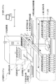
図1は、本実施形態による部品搭載機の外段取りシステムを示す概略模式図である。部品を製品に実装するための部品搭載機1の外段取りシステムSは、部品がセット(配置)された部品供給治具2が複数載置される部品供給台車3(第1の部品供給台車)と、部品搭載機1が生産中に次機種生産に用いる部品供給治具2を準備するための部品供給台車8(第2の部品供給台車)と、部品供給治具2が保管されている部品供給治具保管棚4と、上流の生産システム5の指示により部品供給治具2を部品供給治具保管棚4の保管アドレス(保管位置情報)の位置から取出し、上流の生産システム5の指示により部品供給台車3,8へセットする部品供給治具搬送装置6と、部品供給治具2がセットされた部品供給台車3,8を部品搭載機1へ配置することを自動で行う部品供給台車入替装置7とを含んでいる。
Hereinafter, embodiments of the present invention will be described in detail with reference to the drawings.
FIG. 1 is a schematic diagram showing an external setup system for a component mounting machine according to the present embodiment. The external setup system S of the
部品供給台車入替装置7は、部品供給台車3と部品供給台車8とが、左右移動プレート10の同じ機構上に載っており、また、前後移動プレート9により部品供給台車3,8を、部品搭載機1へ搬入、部品搭載機1から搬出が可能である。なお、左右移動プレート10、前後移動プレート9は、電動アクチュエータなどで実現できる。
In the parts supply
外段取りシステムSは、部品搭載機1で使用する部品供給治具2を部品供給台車3,8へセットする段取り作業、および、部品搭載機1に配置されている部品供給台車3と次回の生産機種用の部品供給治具2がセットされた部品供給台車8との入替えを行う段取り作業を自動化する外段取りシステムである。
The external setup system S is a setup operation for setting the
外段取りシステムSは、部品供給台車3が部品搭載1に配置されプリント基板に部品を実装作業中に、次期生産に使用する部品供給治具2を部品供給治具保管棚4から部品供給治具搬送装置6にてピッキングし移動を行い、部品供給台車8へセットし、生産システム5の指示により、部品供給台車入替装置7にて部品供給台車3から部品供給台車8への入替えを行うものである。これにより、部品搭載機1に対する一連の外段取り作業が自動で行える。
In the external setup system S, the
部品供給治具保管棚4は、前記したように部品供給治具2の保管先を識別するための保管アドレス(保管位置情報)を持ち、この部品供給治具の保管アドレスと、部品供給治具の治具Noと部品の部品コードとが上流の生産システム5で紐付けされており、部品供給治具搬送装置6は、生産システムの段取情報により部品供給治具保管棚4の部品供給治具2の配置位置に移動し、部品供給治具2をピッキングすることが可能である。部品供給治具保管棚4には部品供給治具2が同じ間隔、複数段に配置されている。部品供給治具2のクランプ部位は部品供給治具2の取っ手、もしくは治具本体である。
The component supply jig storage shelf 4 has a storage address (storage position information) for identifying the storage destination of the
部品供給治具2は、サイズ(大きさ)が異なるため、部品供給治具搬送装置6のアームに取り付けられるハンドは、ストッカーにサイズ別に保管されており、ピッキングする部品供給治具2により、変更することができる。
Since the
また、部品供給台車3,8へ部品供給治具2をセットするチャンネルも生産システム5の段取情報に登録されており、部品供給治具搬送装置6は、生産システム5の情報により指定の部品供給台車3,8のチャンネルへ部品供給治具2をセットすることが可能である。
A channel for setting the
さらに、生産機種変更時の部品供給台車3,8の入替えの際に、製品の生産終了情報が部品搭載機1から上流の生産システム5へ送信され、生産終了情報を受信した生産システム5は、部品供給台車入替装置7へ作業指示を送信する。作業指示を受信した外段取りシステムSの部品供給台車入替装置7は、既に部品搭載機1に配置されている部品供給台車3が載った搬送トレイ(前後移動プレート9)を引き戻し、引き戻し完了後、指定の位置へ部品供給台車3を退避させる。同時に部品供給台車入替装置7に載った部品供給治具2が準備された部品供給台車8を部品搭載機1前まで移動させると搬送トレイを押し出し、部品搭載機1へ配置することを自動で行う。これにより、部品搭載機1の外段取りシステムSは、人手で行ってきた部品供給治具2の選び出し、部品供給治具2の部品供給台車3,8へのセット、部品供給台車3,8の入替え作業からなる一連の段取り作業を自動で行う。
Furthermore, when the
本実施形態では、具体例としてプリント基板の表面実装部品搭載作業について説明を行う。先ず、プリント基板の表面実装部品搭載の生産がスタートすると、外段取りシステムSの部品供給治具搬送装置6は、部品搭載機1から搬出され所定の場所へ退避された部品供給台車8から、上流の生産システム5からの指示によって、前回の機種生産で使用した部品供給治具2のうち、次機種生産で使用しない部品供給治具2を、アームによりピッキングし、部品供給治具2を部品供給治具保管棚4へ搬送して部品供給治具保管棚4へ収納する。このとき、部品供給治具搬送装置6は、部品供給治具2の取っ手などの部位をクランプすることで掴むことができる。移動はラック&ピニオン方式であり、高速に動くものとする。なお、部品搭載機1の外段取りシステムSは、採用部品種が増えて部品供給治具保管棚4の収納量を増やす場合、ラック&ピニオン方式のため、増設が簡単である。
In the present embodiment, a surface mounting component mounting operation on a printed circuit board will be described as a specific example. First, when the production of the surface mounting component mounting on the printed circuit board is started, the component supply
収納する部品供給治具保管棚4は、新規に部品が採用された時点で部品供給治具保管棚4の保管アドレスが決められているものとする。但し、部品供給治具保管棚4に採番された保管アドレスは、使用頻度により定期的に見直しがかかり、使用頻度、使用量が多い部品は部品搭載機1の近くの保管位置4に再設定される。
It is assumed that the storage address of the component supply jig storage shelf 4 is determined when the component supply jig storage shelf 4 to be stored is newly adopted. However, the storage address assigned to the parts supply jig storage shelf 4 is periodically reviewed according to the frequency of use, and parts that are frequently used and used are reset to the storage position 4 near the
次に、部品供給治具搬送装置6は、部品供給治具保管棚4へ部品供給治具2が収納された後に、上流の生産システム5により、次生産機種で使用する部品供給治具2を部品供給治具保管棚4から取出し、搬送し、部品供給台車8の指定のチャンネルへのセットを自動で行う。
Next, after the
すなわち、部品供給治具搬送装置6は、部品供給台車8からピッキングした部品供給治具2を部品供給治具保管棚4へ収納し、また、部品供給治具2を部品供給治具保管棚4から取出し、部品供給台車8へセットすることができる。
That is, the component supply
部品供給台車8上の部品供給治具2の入替えの作業が終了すると、外段取りシステムSは、上流の生産システム5へ作業完了信号を送信する。次に、部品搭載機1が現在の生産を終了し、次機種の段取り替えが開始できるようになると、上流の生産システム5から外段取りシステムSの部品供給台車入替装置7へ段取り替え要求信号を送信する。
When the replacement work of the
部品供給台車入替装置7は、段取り替え要求信号を受信すると、部品搭載が終了した部品供給台車3を部品搭載機1から搬出する。
When receiving the setup change request signal, the component supply
次に、搬出された部品供給台車3を所定の退避場所へ移動させる。併せて、部品供給台車8を部品搭載機1へ搬入する。この時点で段取り替え終了信号を上流の生産システム5へ送信し、部品供給治具搬送装置6が動き出し、上流の生産システム5からの指示により、所定の退避場所に移動した部品供給台車3上の部品供給治具2をピッキングし、移動し部品供給治具保管棚4へ収納する。
Next, the carried-out parts supply
部品切れに伴う部品補充方法については、同じ部品がセットされた部品供給治具2について複数本を部品供給治具保管棚4へ準備しておくことで、部品切れ時は同じ部品コードの他の部品供給治具2を使用することができる。また、部品供給治具2が部品供給治具保管棚4へ保管されている際に、生産システム5が部品供給治具2にセットされた部品残量と次生産機種での部品使用量の確認を行い、不足する場合は部品供給治具保管棚4の部品補給側にあるLED(Light Emitting Diode)11を点滅させ、作業者15(図2参照)へ部品補充を促すことができる。
As for the part replenishment method when parts are out of stock, by preparing a plurality of parts supply
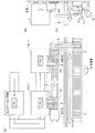
図2は、生産ラインに適用した部品搭載機の外段取りシステムを示す構成図である。図2(a)は、上部から生産ラインをみた説明図であり、図2(b)は、部品搭載機1の側面からの視図であり、図2(c)は、部品供給治具2を含む部品供給治具保管棚4および部品供給治具搬送装置6の側面からの視図である。なお、図2(c)においては、内部に配置されている部品供給治具2がわかるように記載している。
FIG. 2 is a configuration diagram showing an external setup system for a component mounting machine applied to a production line. 2A is an explanatory view of the production line as viewed from above, FIG. 2B is a view from the side of the
図2(a)に示す生産ラインは、はんだペースト印刷機、部品搭載機1A(1)、部品搭載機1B(1)の順番でプリント基板(プラグインボード(PI)またはPCBともいう。)が自動搬送され表面実装部品を搭載する表面実装搭載ラインである。生産稼動中に部品搭載機1Aと部品搭載機1Bとについて一連で段取り作業を行う。2台の部品供給台車8A,8Bからセットされている部品供給治具2を部品供給治具搬送装置6が部品供給治具保管棚4へ戻す。また、生産システム5からの指示により外段取りシステムSの部品供給治具保管棚4から部品供給治具搬送装置6が部品供給治具2をピッキングし、2台の部品供給台車8A,8Bへセットする。なお、部品供給治具2への部品補充作業は、部品供給治具保管棚4の反対側(作業者15がいる側)から部品補充を行うことができる。
The production line shown in FIG. 2A includes a printed circuit board (also referred to as a plug-in board (PI) or PCB) in the order of a solder paste printer, a
図2(c)に示すように、部品供給治具搬送装置6は、アーム6aを上下に移動させること(図2では左右の矢印方向)ができ、部品供給治具保管棚4の上下段に配置された部品供給治具2を取出し、また、部品供給治具保管棚4の上下段に部品供給治具2を戻すことができる。
As shown in FIG. 2 (c), the component supply
本実施形態では、図2(b)、図2(c)に示すように、外段取りシステムSは、床面上に部品搭載機1と部品供給治具保管棚4との間に部品供給治具搬送装置6が設置されており、部品供給治具保管棚4は、部品供給治具搬送装置6に面する側の開口が、部品供給治具搬送装置6のアーム6aの出入口となっており、部品供給治具搬送装置6に面する側と反対となる側(部品補充面側)の開口が、部品補充の補充口となっている。作業者15は、部品補充に際し、部品供給治具搬送装置6に面する側に立ち入る必要はなく、部品供給治具保管棚4は、部品供給治具搬送装置6に対する作業者15の防護柵の機能がある。また、部品供給治具保管棚4の部品補充面側の一面に、部品補充を告知するLED11を配置しているので、作業者15は、補充の必要性のある補充供給治具2の位置を一目で視認することができ、部品補充側の開口を通じて、部品供給治具2を出し入れしやすく、部品補充の作業効率向上の効果がある。
In this embodiment, as shown in FIGS. 2 (b) and 2 (c), the outer setup system S has a component supply control between the
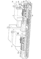
図3は、図2に示す生産ラインの一例を示す斜視図である。図3においては、部品供給治具保管棚4内の部品供給治具2の配置状況は、2点鎖線で記載している。部品供給台車入替装置7の左右移動プレート10上に高さ調整のベース10aを設け、ベース10aに、図2に示す前後移動プレート9の実施形態として、レール9aを設置し、そのレール9a上を部品供給台車3,8A(8),8B(8)が移動するようにしている。移動には、電動アクチュエータ、例えば、電動シリンダを用いるとよい。部品供給治具搬送装置6は、上下移動、左右移動、前後移動ができるようになっている。
FIG. 3 is a perspective view showing an example of the production line shown in FIG. In FIG. 3, the arrangement status of the
部品供給台車3(第1の部品供給台車)および部品供給台車8(第2の部品供給台車)は、同一の移動するベース台(例えば、左右移動プレート10とベース10a)上で、かつ、前記移動するベース台の移動方向と直角な方向のレール9a上にそれぞれ載置されているので、第1の部品供給台車および第2の部品供給台車は、左右および前後に移動することができる。同一の移動するベース台上に設置することにより、駆動源をひとつで構成することもできる。また、ベース10aは、フレーム(枠状)をひとつにして軽量化している。個々にフレームを構成した場合に比べて縦枠の数を減らせることになる。なお、フレームは、通常、横枠と縦枠により構成される。
The component supply cart 3 (first component supply cart) and the component supply cart 8 (second component supply cart) are on the same moving base table (for example, the left and right moving
図4は、生産ラインの制御システムの構成を示す説明図である。適宜図1を参照して説明する。制御システムは、生産システム5と、生産ラインに設置された複数の部品搭載機1と、該部品搭載機1の部品の外段取りをする複数の外段取りシステムSとで構成されている。複数の部品搭載機1と、複数の外段取りシステムSとは、ネットワーク30を介し相互に通信可能に接続されている。
FIG. 4 is an explanatory diagram showing a configuration of a production line control system. This will be described with reference to FIG. The control system includes a production system 5, a plurality of
外段取りシステムSの処理部20は、生産システム5からの作業指示を、部品供給台車入替装置7、部品供給治具搬送装置6、部品供給治具保管棚4に指令し、また、部品供給台車入替装置7、部品供給治具搬送装置6、部品供給治具保管棚4からの作業指示に対する制御結果情報を生産システム5に送信する。
The
外段取りシステムSは、既に説明したように、部品搭載機1で使用する部品供給治具2を部品供給台車3,8へセットする段取り作業、および、部品搭載機1にセットされている部品供給台車(例えば、部品供給台車3)と次回の生産機種用の部品供給治具2が準備された部品供給台車(例えば、部品供給台車8)の入替えを行う作業を自動化することができる。具体的には、部品供給治具搬送装置6にて部品供給治具保管棚4から部品供給治具2をピッキングし移動を行い、部品搭載機1へ配置する部品供給台車3,8にセットし、部品供給治具2が準備された部品供給台車3,8を、部品供給台車入替装置7にて搬送して入替えを行うものである。これにより、部品搭載機1への一連の部品段取り作業が自動で行え、多品種少量生産形態のラインにおいても段取り作業は量産ライン並になり、段取り作業者レスにすることができる。さらに生産システム5の自動化システムにより、ヒューマンエラーなどの不良要因を排除することができる。
As described above, the external setup system S sets up the
外段取りシステムSの機能としては、部品供給治具保管棚4には部品供給治具2の保管先が分かるための保管アドレス(保管位置情報)が付され、この部品供給治具2の保管アドレスと、部品供給治具の治具Noと、部品供給治具にセットされている部品の部品コードとが上流の生産システム5で紐付けされている。部品供給治具搬送装置6は、生産システム5の段取情報により対象の部品供給治具をピッキングすることが可能である。また、部品供給台車3,8へ部品供給治具2をセットするためのチャンネルも生産システム5の段取情報に登録されており、部品供給治具搬送装置6は生産システム5の情報により指定の部品供給台車3,8のチャンネルへ部品供給治具2をセットすることが可能である。
As a function of the external setup system S, a storage address (storage position information) for identifying the storage destination of the
さらに、生産機種変更時の部品供給台車入替え時には、製品の生産終了情報が部品搭載機1から上流の生産システム5へ送信され、生産システム5は、外段取りシステムSの部品供給台車入替装置7へ作業指示を出す。部品供給台車入替装置7は、既に部品搭載機1に配置されている部品供給台車(例えば、部品供給台車3)が載った搬送トレイ(前後移動プレート9に相当)を引き戻し、引き戻し完了後、指定の位置へ部品供給台車3を退避させる。同時に部品供給台車入替装置7に載った部品供給治具2が準備された部品供給台車(例えば、部品供給台車8)を部品搭載機1前まで移動させると搬送トレイを押し出し、部品搭載機1へ配置することを自動化することができ、さらにヒューマンエラーなどの不良要因を排除することができる。
Further, at the time of replacement of the parts supply cart when the production model is changed, the production end information of the product is transmitted from the
部品供給治具搬送装置6は、生産システム5から部品供給治具保管棚4内の部品供給治具2の保管位置情報、部品供給台車3,8の台車識別情報、部品供給台車3,8上の位置を示すチャンネル情報、部品供給治具保管棚4への保管指示(あるいは収納指示)か部品供給治具保管棚4からの取出し指示かの作業指示情報を含む段取情報を受信すると、段取情報に基づいて作業指示が保管指示である場合、台車識別情報およびチャンネル情報に基づいて部品供給治具2を部品供給台車3,8から取外して搬送し、部品供給治具保管棚4内の保管位置情報に基づいて取外した部品供給治具2を戻すことができる。
The component supply
部品供給台車3(第1の部品供給台車)および部品供給台車8(第2の部品供給台車)は、同一の移動するベース台(例えば、左右移動プレート10とベース10a)上で、かつ、前記移動するベース台の移動方向と直角な方向のレール9a上にそれぞれ載置されているので、第1の部品供給台車および第2の部品供給台車は、左右および前後に移動することができる。
The component supply cart 3 (first component supply cart) and the component supply cart 8 (second component supply cart) are on the same moving base table (for example, the left and right moving
本実施形態の外段取りシステムSは、定期的(例えば、月や期ごと)に生産機種予算情報から使用頻度や使用量が多い部品供給治具を、入替え作業時の移動距離を短くする段取情報を生産システム5から受信すると、部品供給治具搬送装置6に受信した段取情報を送信し、段取情報に基づいて部品供給治具保管棚4内の部品供給治具2の配置替えをすることができる。
The external setup system S of the present embodiment is a setup that shortens the moving distance during replacement work for parts supply jigs that are frequently used or used from production model budget information on a regular basis (for example, every month or period). When the information is received from the production system 5, the received setup information is transmitted to the component supply
1,1A,1B 部品搭載機
2 部品供給治具
3 部品供給台車(第1の部品供給台車)
4 部品供給治具保管棚
5 生産システム
6 部品供給治具搬送装置
7 部品供給台車入替装置
8 部品供給台車(第2の部品供給台車)
9 前後移動プレート
10 左右移動プレート
11 LED
15 作業者
20 処理部
30 ネットワーク
S 外段取りシステム
1, 1A, 1B
4 Parts supply jig storage shelf 5
9 Forward / backward moving
15
Claims (5)
第1の生産機種用の複数の部品供給治具が載置される第1の部品供給台車と、
次に生産される第2の生産機種用の複数の部品供給治具が載置される第2の部品供給台車と、
前記第1の部品供給台車と前記第2の部品供給台車とを入替えて前記部品搭載機の所定位置に配置する部品供給台車入替装置と、
前記第1の部品供給台車または前記第2の部品供給台車へ載置される前記部品供給治具が保管された部品供給治具保管棚と、
前記第1の部品供給台車の前記部品供給治具が使用されている期間に、前記第2の部品供給台車から前記部品供給治具を取外して搬送し部品供給治具保管棚に戻し、かつ、前記部品供給治具保管棚から前記部品供給治具を取外して搬送し、前記第2の部品供給台車に前記部品供給治具を載置する部品供給治具搬送装置とを備え、
前記部品供給台車入替装置は、生産システムから部品供給台車の入替え指示を受信すると、前記部品搭載機に配置されている前記第1の部品供給台車を引き出し、所定場所へ移動させるとともに、前記第2の部品供給台車を前記部品搭載機の前記所定位置に配置する
ことを特徴とする外段取りシステム。 An external setup system for a component mounting machine in which a component supply carriage is arranged in the component mounting machine for mounting the component,
A first component supply carriage on which a plurality of component supply jigs for the first production model are placed;
A second component supply carriage on which a plurality of component supply jigs for a second production model to be produced are placed;
A component supply cart replacement device that replaces the first component supply cart and the second component supply cart and arranges the first component supply cart at a predetermined position of the component mounting machine;
A component supply jig storage shelf in which the component supply jig placed on the first component supply carriage or the second component supply carriage is stored;
Removing and transporting the component supply jig from the second component supply carriage and returning it to the component supply jig storage shelf during a period in which the component supply jig of the first component supply carriage is being used; and A component supply jig conveying device that removes and conveys the component supply jig from the component supply jig storage shelf, and places the component supply jig on the second component supply carriage;
When the parts supply cart replacement device receives a replacement instruction for the component supply cart from the production system, the parts supply cart replacement apparatus pulls out the first component supply cart arranged in the component mounting machine and moves it to a predetermined location. The component supply cart is arranged at the predetermined position of the component mounting machine.
前記段取情報に基づいて前記作業指示が保管指示である場合、前記台車識別情報および前記チャンネル情報に基づいて前記部品供給治具を前記第2の部品供給台車から取外して搬送し、前記保管位置情報に基づいて前記取外した部品供給治具を前記部品供給治具保管棚内に戻す
ことを特徴とする請求項1に記載の外段取りシステム。 The component supply jig transporting device stores storage position information of a component supply jig in the component supply jig storage shelf from the production system, vehicle identification information of the second component supply vehicle, and the second component supply vehicle. When receiving setup information including channel information indicating the upper position, work instruction information such as a storage instruction to the component supply jig storage shelf or an instruction to take out from the component supply jig storage shelf,
When the work instruction is a storage instruction based on the setup information, the component supply jig is detached from the second component supply carriage based on the cart identification information and the channel information, and is transported. The external setup system according to claim 1, wherein the removed component supply jig is returned to the component supply jig storage shelf based on the information.
ことを特徴とする請求項1に記載の外段取りシステム。 The first component supply cart and the second component supply cart are respectively mounted on the same moving base table and on a rail in a direction perpendicular to the moving direction of the moving base table. The external setup system according to claim 1, wherein:
ことを特徴とする請求項1に記載の外段取りシステム。 The external setup system periodically receives the setup information for shortening the moving distance at the time of replacement work from the production system regarding the part supply jig having a high use frequency and the use amount from the production model budget information. 2. The outside according to claim 1, wherein the setup information is transmitted to a tool conveying device, and the component supply jig in the component supply jig storage shelf is rearranged based on the setup information. Setup system.
前記部品供給治具保管棚は、前記部品供給治具搬送装置に面する側の開口が、該部品供給治具搬送装置のアームの出入口となっており、前記部品供給治具搬送装置に面する側と反対となる側の開口が部品補充の補充口となっている
ことを特徴とする請求項1に記載の外段取りシステム。 In the outer setup system, the component supply jig transfer device is installed on the floor between the component mounting machine and the component supply jig storage shelf,
The component supply jig storage shelf has an opening on the side facing the component supply jig conveyance device serving as an entrance / exit of an arm of the component supply jig conveyance device, and faces the component supply jig conveyance device. The external setup system according to claim 1, wherein an opening on a side opposite to the side serves as a replenishing port for replenishing parts.
Priority Applications (1)
| Application Number | Priority Date | Filing Date | Title |
|---|---|---|---|
| JP2010285297A JP5476288B2 (en) | 2010-12-22 | 2010-12-22 | External setup system for component mounting machines |
Applications Claiming Priority (1)
| Application Number | Priority Date | Filing Date | Title |
|---|---|---|---|
| JP2010285297A JP5476288B2 (en) | 2010-12-22 | 2010-12-22 | External setup system for component mounting machines |
Publications (2)
| Publication Number | Publication Date |
|---|---|
| JP2012134331A true JP2012134331A (en) | 2012-07-12 |
| JP5476288B2 JP5476288B2 (en) | 2014-04-23 |
Family
ID=46649584
Family Applications (1)
| Application Number | Title | Priority Date | Filing Date |
|---|---|---|---|
| JP2010285297A Active JP5476288B2 (en) | 2010-12-22 | 2010-12-22 | External setup system for component mounting machines |
Country Status (1)
| Country | Link |
|---|---|
| JP (1) | JP5476288B2 (en) |
Cited By (17)
| Publication number | Priority date | Publication date | Assignee | Title |
|---|---|---|---|---|
| WO2015040079A1 (en) * | 2013-09-18 | 2015-03-26 | Mycronic AB | Method, system and device for impoved storage and handling of components |
| EP3020661A4 (en) * | 2013-07-12 | 2016-08-10 | Fuji Machine Mfg | Automatic feeder placement control device and control method |
| JPWO2015037099A1 (en) * | 2013-09-12 | 2017-03-02 | 富士機械製造株式会社 | Substrate working system, working method, and feeder transfer method |
| WO2017033268A1 (en) * | 2015-08-25 | 2017-03-02 | 富士機械製造株式会社 | Component mounting line |
| JPWO2017029704A1 (en) * | 2015-08-18 | 2018-05-31 | 株式会社Fuji | Parts mounting machine |
| JP2019091942A (en) * | 2019-03-06 | 2019-06-13 | パナソニックIpマネジメント株式会社 | Component preparation instruction system and component preparation instruction method |
| EP3484258A4 (en) * | 2016-07-08 | 2019-07-10 | Fuji Corporation | Component-mounting system and management device |
| WO2020003581A1 (en) * | 2018-06-29 | 2020-01-02 | パナソニックIpマネジメント株式会社 | Operation system and feeder carriage transfer method |
| JP2020010069A (en) * | 2018-02-07 | 2020-01-16 | 株式会社Fuji | Cassette feeder replacement system of component mounting machine |
| JP2020014020A (en) * | 2015-08-25 | 2020-01-23 | 株式会社Fuji | Component mounting line |
| JP2020074390A (en) * | 2019-10-18 | 2020-05-14 | 株式会社Fuji | Cassette type feeder replacement system for component mounting machine |
| WO2020121402A1 (en) * | 2018-12-11 | 2020-06-18 | 株式会社Fuji | Mounting system and method of arranging component feeding units |
| WO2020157856A1 (en) * | 2019-01-30 | 2020-08-06 | 株式会社Fuji | Management device, mounting device, mounting system, and management method |
| CN113348736A (en) * | 2019-02-18 | 2021-09-03 | 株式会社富士 | Setup device for setup work of setup change |
| JP2022119992A (en) * | 2019-02-13 | 2022-08-17 | 株式会社Fuji | feeder storage |
| EP4180376A1 (en) * | 2021-11-11 | 2023-05-17 | Totech Europe BV | Pick and place unit for a reel storage cabinet with an access opening |
| DE112020007731T5 (en) | 2020-12-25 | 2023-08-10 | Yamaha Hatsudoki Kabushiki Kaisha | Component storage system, component storage and magazine preparation method |
Citations (7)
| Publication number | Priority date | Publication date | Assignee | Title |
|---|---|---|---|---|
| JPH066084A (en) * | 1992-06-19 | 1994-01-14 | Olympus Optical Co Ltd | Automatic electronic part installation equipment |
| JPH1034459A (en) * | 1996-07-17 | 1998-02-10 | Fujitsu Ltd | Production control system provided with smt line |
| JPH1117389A (en) * | 1997-06-20 | 1999-01-22 | Matsushita Electric Ind Co Ltd | Electronic component fitting machine |
| JP2008103418A (en) * | 2006-10-17 | 2008-05-01 | Yamaha Motor Co Ltd | Mounting machine and feeder |
| JP2008201571A (en) * | 2007-02-22 | 2008-09-04 | Daido Steel Co Ltd | Operating method of automated warehouse |
| WO2010084542A1 (en) * | 2009-01-23 | 2010-07-29 | 村田機械株式会社 | Automated warehouse |
| JP2010267696A (en) * | 2009-05-13 | 2010-11-25 | Hitachi High-Tech Instruments Co Ltd | Board conveyance apparatus |
-
2010
- 2010-12-22 JP JP2010285297A patent/JP5476288B2/en active Active
Patent Citations (7)
| Publication number | Priority date | Publication date | Assignee | Title |
|---|---|---|---|---|
| JPH066084A (en) * | 1992-06-19 | 1994-01-14 | Olympus Optical Co Ltd | Automatic electronic part installation equipment |
| JPH1034459A (en) * | 1996-07-17 | 1998-02-10 | Fujitsu Ltd | Production control system provided with smt line |
| JPH1117389A (en) * | 1997-06-20 | 1999-01-22 | Matsushita Electric Ind Co Ltd | Electronic component fitting machine |
| JP2008103418A (en) * | 2006-10-17 | 2008-05-01 | Yamaha Motor Co Ltd | Mounting machine and feeder |
| JP2008201571A (en) * | 2007-02-22 | 2008-09-04 | Daido Steel Co Ltd | Operating method of automated warehouse |
| WO2010084542A1 (en) * | 2009-01-23 | 2010-07-29 | 村田機械株式会社 | Automated warehouse |
| JP2010267696A (en) * | 2009-05-13 | 2010-11-25 | Hitachi High-Tech Instruments Co Ltd | Board conveyance apparatus |
Cited By (38)
| Publication number | Priority date | Publication date | Assignee | Title |
|---|---|---|---|---|
| EP3020661A4 (en) * | 2013-07-12 | 2016-08-10 | Fuji Machine Mfg | Automatic feeder placement control device and control method |
| JPWO2015037099A1 (en) * | 2013-09-12 | 2017-03-02 | 富士機械製造株式会社 | Substrate working system, working method, and feeder transfer method |
| US11465845B2 (en) | 2013-09-18 | 2022-10-11 | Mycronic AB | Method, system and device for identifying a bin in an SMT system |
| EP3873185A3 (en) * | 2013-09-18 | 2021-09-22 | Mycronic Ab | Methods, system and device for improved storage and handling of components |
| JP2016531449A (en) * | 2013-09-18 | 2016-10-06 | マイクロニック アーベーMycronic Ab | Method, system and apparatus for improved storage and handling of parts |
| US10633185B2 (en) | 2013-09-18 | 2020-04-28 | Mycronic AB | Method, system and device for identifying a bin in an SMT system |
| JP2016532315A (en) * | 2013-09-18 | 2016-10-13 | マイクロニック アーベーMycronic Ab | Method, system and apparatus for redistribution of parts and bins in an SMD warehouse |
| JP2019140405A (en) * | 2013-09-18 | 2019-08-22 | マイクロニック アーベーMycronic Ab | Method, system and device for improved storage and handling of component |
| WO2015040079A1 (en) * | 2013-09-18 | 2015-03-26 | Mycronic AB | Method, system and device for impoved storage and handling of components |
| US10322879B2 (en) | 2013-09-18 | 2019-06-18 | Mycronic AB | Method, system and device for identifying a bin in an SMT system |
| JPWO2017029704A1 (en) * | 2015-08-18 | 2018-05-31 | 株式会社Fuji | Parts mounting machine |
| JPWO2017033268A1 (en) * | 2015-08-25 | 2018-06-14 | 株式会社Fuji | Component mounting line |
| JP2020014020A (en) * | 2015-08-25 | 2020-01-23 | 株式会社Fuji | Component mounting line |
| WO2017033268A1 (en) * | 2015-08-25 | 2017-03-02 | 富士機械製造株式会社 | Component mounting line |
| EP3484258A4 (en) * | 2016-07-08 | 2019-07-10 | Fuji Corporation | Component-mounting system and management device |
| EP3780929A1 (en) * | 2016-07-08 | 2021-02-17 | Fuji Corporation | Component-mounting system and management device |
| JP2020010069A (en) * | 2018-02-07 | 2020-01-16 | 株式会社Fuji | Cassette feeder replacement system of component mounting machine |
| JPWO2020003581A1 (en) * | 2018-06-29 | 2020-07-02 | パナソニックIpマネジメント株式会社 | Work system and feeder carriage method |
| CN112219461B (en) * | 2018-06-29 | 2022-01-18 | 松下知识产权经营株式会社 | Work system and method for conveying feeder carriage |
| US11950369B2 (en) * | 2018-06-29 | 2024-04-02 | Panasonic Intellectual Property Management Co., Ltd. | Work system and feeder carriage transfer method |
| CN112219461A (en) * | 2018-06-29 | 2021-01-12 | 松下知识产权经营株式会社 | Work system and method for conveying feeder carriage |
| JP7113196B2 (en) | 2018-06-29 | 2022-08-05 | パナソニックIpマネジメント株式会社 | Work system, feeder truck transfer method, and feeder truck connection method |
| JP2021057609A (en) * | 2018-06-29 | 2021-04-08 | パナソニックIpマネジメント株式会社 | Working system, transport method of items to be transported, and coupling method of items to be transported |
| WO2020003581A1 (en) * | 2018-06-29 | 2020-01-02 | パナソニックIpマネジメント株式会社 | Operation system and feeder carriage transfer method |
| WO2020121402A1 (en) * | 2018-12-11 | 2020-06-18 | 株式会社Fuji | Mounting system and method of arranging component feeding units |
| JPWO2020121402A1 (en) * | 2018-12-11 | 2021-09-27 | 株式会社Fuji | How to arrange the mounting system and component supply unit |
| JP7329537B2 (en) | 2018-12-11 | 2023-08-18 | 株式会社Fuji | Placement method of mounting system and component supply unit |
| JPWO2020157856A1 (en) * | 2019-01-30 | 2021-11-25 | 株式会社Fuji | Management device, mounting device, mounting system and management method |
| JP7220237B2 (en) | 2019-01-30 | 2023-02-09 | 株式会社Fuji | Management device, mounting device, mounting system and management method |
| WO2020157856A1 (en) * | 2019-01-30 | 2020-08-06 | 株式会社Fuji | Management device, mounting device, mounting system, and management method |
| JP7538834B2 (en) | 2019-02-13 | 2024-08-22 | 株式会社Fuji | Feeder storage and component mounting system |
| JP2022119992A (en) * | 2019-02-13 | 2022-08-17 | 株式会社Fuji | feeder storage |
| CN113348736A (en) * | 2019-02-18 | 2021-09-03 | 株式会社富士 | Setup device for setup work of setup change |
| CN113348736B (en) * | 2019-02-18 | 2022-11-18 | 株式会社富士 | Setup device for setup work of setup change |
| JP2019091942A (en) * | 2019-03-06 | 2019-06-13 | パナソニックIpマネジメント株式会社 | Component preparation instruction system and component preparation instruction method |
| JP2020074390A (en) * | 2019-10-18 | 2020-05-14 | 株式会社Fuji | Cassette type feeder replacement system for component mounting machine |
| DE112020007731T5 (en) | 2020-12-25 | 2023-08-10 | Yamaha Hatsudoki Kabushiki Kaisha | Component storage system, component storage and magazine preparation method |
| EP4180376A1 (en) * | 2021-11-11 | 2023-05-17 | Totech Europe BV | Pick and place unit for a reel storage cabinet with an access opening |
Also Published As
| Publication number | Publication date |
|---|---|
| JP5476288B2 (en) | 2014-04-23 |
Similar Documents
| Publication | Publication Date | Title |
|---|---|---|
| JP5476288B2 (en) | External setup system for component mounting machines | |
| JP6738419B2 (en) | Component mounting system and management device | |
| JP6300808B2 (en) | On-board working system and feeder transfer method | |
| KR960015906B1 (en) | Method and apparatus for manufacturing printed wiring boards | |
| US11445651B2 (en) | Substrate work system | |
| US11864324B2 (en) | Moving work management device, moving work device, mounting system, and moving work management method | |
| CN114600568B (en) | Warehouse system | |
| WO2016084143A1 (en) | Tool exchange assistance system and tool exchange assistance method for component mounting line | |
| JP4372522B2 (en) | Surface mount machine | |
| CN114206625A (en) | Method and system for automated individual replacement in a stencil printer | |
| CN113366934B (en) | Component type management device | |
| WO2016147390A1 (en) | Component mounting line, and component mounting line setup method | |
| WO2021192557A1 (en) | Carrier tape processing device and carrier tape processing method | |
| JPWO2004064473A1 (en) | Substrate carrying-in method in mounting line, substrate production system, and substrate production method in substrate production system | |
| CN114303449B (en) | Simulation device and simulation method | |
| JP7336645B2 (en) | PARTS MANAGEMENT DEVICE AND PARTS MANAGEMENT METHOD | |
| CN114080869B (en) | Auxiliary method and auxiliary device for product changing and adjusting operation | |
| JP5473465B2 (en) | Electronic component mounting equipment | |
| JP7170176B2 (en) | PRODUCTION PLANNING METHOD, PRODUCTION PLANNING APPARATUS, AND PRODUCTION METHOD | |
| KR101868156B1 (en) | Electronic component mounting method and mounting apparatus | |
| JP7289963B2 (en) | Parts type management device | |
| US20230114831A1 (en) | Carrier-tape processing device and carrier-tape processing method | |
| WO2024079881A1 (en) | Component mounting system and mounting tool feeder | |
| WO2022070410A1 (en) | Production assistance device | |
| WO2024025650A1 (en) | Systems and methods for replacing items in a stencil printer |
Legal Events
| Date | Code | Title | Description |
|---|---|---|---|
| A621 | Written request for application examination |
Free format text: JAPANESE INTERMEDIATE CODE: A621 Effective date: 20130201 |
|
| A977 | Report on retrieval |
Free format text: JAPANESE INTERMEDIATE CODE: A971007 Effective date: 20131114 |
|
| A131 | Notification of reasons for refusal |
Free format text: JAPANESE INTERMEDIATE CODE: A131 Effective date: 20131119 |
|
| A521 | Written amendment |
Free format text: JAPANESE INTERMEDIATE CODE: A523 Effective date: 20131213 |
|
| TRDD | Decision of grant or rejection written | ||
| A01 | Written decision to grant a patent or to grant a registration (utility model) |
Free format text: JAPANESE INTERMEDIATE CODE: A01 Effective date: 20140114 |
|
| A61 | First payment of annual fees (during grant procedure) |
Free format text: JAPANESE INTERMEDIATE CODE: A61 Effective date: 20140207 |
|
| R150 | Certificate of patent or registration of utility model |
Ref document number: 5476288 Country of ref document: JP Free format text: JAPANESE INTERMEDIATE CODE: R150 Free format text: JAPANESE INTERMEDIATE CODE: R150 |