JP2012123977A - Compound lamp unit of passenger car - Google Patents
Compound lamp unit of passenger car Download PDFInfo
- Publication number
- JP2012123977A JP2012123977A JP2010272664A JP2010272664A JP2012123977A JP 2012123977 A JP2012123977 A JP 2012123977A JP 2010272664 A JP2010272664 A JP 2010272664A JP 2010272664 A JP2010272664 A JP 2010272664A JP 2012123977 A JP2012123977 A JP 2012123977A
- Authority
- JP
- Japan
- Prior art keywords
- lamp unit
- light guide
- light
- lamp
- passenger car
- Prior art date
- Legal status (The legal status is an assumption and is not a legal conclusion. Google has not performed a legal analysis and makes no representation as to the accuracy of the status listed.)
- Granted
Links
- 150000001875 compounds Chemical class 0.000 title abstract description 6
- 239000002131 composite material Substances 0.000 claims description 15
- 230000001771 impaired effect Effects 0.000 description 1
Images


Classifications
-
- F—MECHANICAL ENGINEERING; LIGHTING; HEATING; WEAPONS; BLASTING
- F21—LIGHTING
- F21S—NON-PORTABLE LIGHTING DEVICES; SYSTEMS THEREOF; VEHICLE LIGHTING DEVICES SPECIALLY ADAPTED FOR VEHICLE EXTERIORS
- F21S43/00—Signalling devices specially adapted for vehicle exteriors, e.g. brake lamps, direction indicator lights or reversing lights
- F21S43/20—Signalling devices specially adapted for vehicle exteriors, e.g. brake lamps, direction indicator lights or reversing lights characterised by refractors, transparent cover plates, light guides or filters
- F21S43/235—Light guides
- F21S43/249—Light guides with two or more light sources being coupled into the light guide
-
- B—PERFORMING OPERATIONS; TRANSPORTING
- B60—VEHICLES IN GENERAL
- B60Q—ARRANGEMENT OF SIGNALLING OR LIGHTING DEVICES, THE MOUNTING OR SUPPORTING THEREOF OR CIRCUITS THEREFOR, FOR VEHICLES IN GENERAL
- B60Q1/00—Arrangement of optical signalling or lighting devices, the mounting or supporting thereof or circuits therefor
- B60Q1/26—Arrangement of optical signalling or lighting devices, the mounting or supporting thereof or circuits therefor the devices being primarily intended to indicate the vehicle, or parts thereof, or to give signals, to other traffic
- B60Q1/30—Arrangement of optical signalling or lighting devices, the mounting or supporting thereof or circuits therefor the devices being primarily intended to indicate the vehicle, or parts thereof, or to give signals, to other traffic for indicating rear of vehicle, e.g. by means of reflecting surfaces
- B60Q1/304—Adaptations of signalling devices having a part on the vehicle body and another on the boot door
-
- B—PERFORMING OPERATIONS; TRANSPORTING
- B60—VEHICLES IN GENERAL
- B60Q—ARRANGEMENT OF SIGNALLING OR LIGHTING DEVICES, THE MOUNTING OR SUPPORTING THEREOF OR CIRCUITS THEREFOR, FOR VEHICLES IN GENERAL
- B60Q1/00—Arrangement of optical signalling or lighting devices, the mounting or supporting thereof or circuits therefor
- B60Q1/26—Arrangement of optical signalling or lighting devices, the mounting or supporting thereof or circuits therefor the devices being primarily intended to indicate the vehicle, or parts thereof, or to give signals, to other traffic
- B60Q1/32—Arrangement of optical signalling or lighting devices, the mounting or supporting thereof or circuits therefor the devices being primarily intended to indicate the vehicle, or parts thereof, or to give signals, to other traffic for indicating vehicle sides, e.g. clearance lights
- B60Q1/323—Arrangement of optical signalling or lighting devices, the mounting or supporting thereof or circuits therefor the devices being primarily intended to indicate the vehicle, or parts thereof, or to give signals, to other traffic for indicating vehicle sides, e.g. clearance lights on or for doors
- B60Q1/324—Arrangement of optical signalling or lighting devices, the mounting or supporting thereof or circuits therefor the devices being primarily intended to indicate the vehicle, or parts thereof, or to give signals, to other traffic for indicating vehicle sides, e.g. clearance lights on or for doors for signalling that a door is open or intended to be opened
-
- F—MECHANICAL ENGINEERING; LIGHTING; HEATING; WEAPONS; BLASTING
- F21—LIGHTING
- F21S—NON-PORTABLE LIGHTING DEVICES; SYSTEMS THEREOF; VEHICLE LIGHTING DEVICES SPECIALLY ADAPTED FOR VEHICLE EXTERIORS
- F21S43/00—Signalling devices specially adapted for vehicle exteriors, e.g. brake lamps, direction indicator lights or reversing lights
- F21S43/20—Signalling devices specially adapted for vehicle exteriors, e.g. brake lamps, direction indicator lights or reversing lights characterised by refractors, transparent cover plates, light guides or filters
- F21S43/235—Light guides
- F21S43/251—Light guides the light guides being used to transmit light from remote light sources
Abstract
Description
本発明は、ドア端に設けられた第1ランプユニットとボディ端に設けられた第2ランプユニットとが意匠的に一つのまとまりを持ったランプユニットを構成する乗用車の複合ランプユニットに関する。 The present invention relates to a composite lamp unit for a passenger car in which a first lamp unit provided at a door end and a second lamp unit provided at a body end constitute a lamp unit having one unit in design.
上記した乗用車の複合ランプユニットの一例が特許文献1に記載されている。
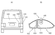
特許文献1に係るリヤランプユニット100は、図6(A)(B)に示すように、乗用車のボディ120側に設けられた点灯ランプ部102とドア122側に設けられた反射ランプ部103とから構成されている。点灯ランプ部102と反射ランプ部103の間は光が通過可能なように透明なレンズ102r,103rにより構成されており、点灯ランプ部102に光源である電球105が設けられている。
前記リヤランプユニット100の場合、点灯ランプ部102と反射ランプ部103とをバランス良く光らせるためには、電球105をリヤランプユニット100の中央に配置する必要があり、前記電球105の位置が制約されるという問題がある。
An example of the above-described composite lamp unit of a passenger car is described in Patent Document 1.
As shown in FIGS. 6A and 6B, the
In the case of the
上記問題を解決するため、図7には光源の光を導く導光体106,107を用いたリヤランプユニット110が記載されている。前記リヤランプユニット110は、ドア端に設けられた第1ランプユニット112とボディ端に設けられた第2ランプユニット113とから構成されている。そして、第1ランプユニット112内に左端位置から右端位置(第2ランプユニットとの境界位置)まで横方向に延びる導光体106が設けられている。また、第2ランプユニット113内には、第1ランプユニット112の導光体106の延長線上位置に、左端位置(第1ランプユニットとの境界位置)から右端位置まで横方向に延びる導光体107が設けられている。そして、第1ランプユニット112では導光体106の左端位置に光源であるLED108が配置されており、第2ランプユニット113では導光体107の右端位置に同じく光源であるLED109が配置されている。
このように、導光体106,107を使用することで光源108,109の配置の自由度が向上する。
In order to solve the above problem, FIG. 7 shows a
As described above, the use of the
上記したリヤランプユニット110の場合、図7に示すように、第1ランプユニット112の導光体106の長さ寸法が第2ランプユニット113の導光体107の長さ寸法よりも大きく設定されている。即ち、第1ランプユニット112の光源108から導光体106の右端位置までの距離は、第2ランプユニット113の光源109から導光体107の左端位置までの距離よりも大きくなる。このため、導光体106,107を通る光の減衰により、第1ランプユニット112の右端位置は第2ランプユニット113の左端位置よりも暗くなる。即ち、第1ランプユニット112と第2ランプユニット113との境界位置近傍で、第1ランプユニット112側が暗く、第2ランプユニット113側が明るくなる。これにより、リヤランプユニット110の一体感が損なわれるという問題がある。
In the case of the
本発明は、上記問題点を解決するためになされたものであり、本発明が解決しようとする課題は、第1ランプユニットと第2ランプユニットとの境界位置近傍で第1ランプユニットと第2ランプユニットとの明るさがばらつかないようにして、複合ランプユニットの一体感を向上させることである。 The present invention has been made to solve the above problems, and the problem to be solved by the present invention is that the first lamp unit and the second lamp unit are located in the vicinity of the boundary position between the first lamp unit and the second lamp unit. It is to improve the sense of unity of the composite lamp unit by preventing the brightness of the lamp unit from varying.
上記した課題は、各請求項の発明によって解決される。
請求項1の発明は、ドア端に設けられた第1ランプユニットとボディ端に設けられた第2ランプユニットとが意匠的に一つのまとまりを持ったランプユニットを構成する乗用車の複合ランプユニットであって、前記第1ランプユニットと第2ランプユニットとは、光源の光を導光体に通すことでその導光体の周囲を照らせるように構成されており、前記第1ランプユニットの導光体を通過した光が前記第2ランプユニットの導光体まで到達し、前記第2ランプユニットの導光体を通過した光が前記第1ランプユニットの導光体まで到達可能なように構成されていることを特徴とする。
The above-described problems are solved by the inventions of the claims.
The invention of claim 1 is a composite lamp unit for a passenger car in which a first lamp unit provided at a door end and a second lamp unit provided at a body end constitute a lamp unit having a single unit in design. The first lamp unit and the second lamp unit are configured to illuminate the periphery of the light guide by passing light from the light source through the light guide, and guide the light from the first lamp unit. The light passing through the body reaches the light guide of the second lamp unit, and the light passing through the light guide of the second lamp unit can reach the light guide of the first lamp unit. It is characterized by.
本発明によると、第1ランプユニットの導光体を通過した光が第2ランプユニットの導光体まで到達し、第2ランプユニットの導光体を通過した光が第1ランプユニットの導光体まで到達可能なように構成されている。このため、第1ランプユニットの導光体と第2ランプユニットの導光体との明るさが均一化される。したがって、第1ランプユニットと第2ランプユニットとの境界位置近傍で第1ランプユニットの明るさと第2ランプユニットの明るさとがばらつくことがない。 According to the present invention, the light passing through the light guide of the first lamp unit reaches the light guide of the second lamp unit, and the light passing through the light guide of the second lamp unit is guided by the first lamp unit. It is configured to reach the body. For this reason, the brightness of the light guide of the first lamp unit and the light guide of the second lamp unit is made uniform. Therefore, the brightness of the first lamp unit and the brightness of the second lamp unit do not vary in the vicinity of the boundary position between the first lamp unit and the second lamp unit.
請求項2の発明によると、第1ランプユニットと第2ランプユニットとの導光体は棒状に形成されて、前記第1ランプユニットの導光体の軸方向延長線上に第2ランプユニットの導光体が配置されており、前記第1ランプユニットの導光体の軸方向端面と第2ランプユニットの導光体の軸方向端面間で光が通過できるように構成されていることを特徴とする。 According to the invention of claim 2, the light guides of the first lamp unit and the second lamp unit are formed in a rod shape, and the second lamp unit is guided on the axial extension line of the light guide of the first lamp unit. A light body is disposed, and is configured to allow light to pass between an axial end surface of the light guide of the first lamp unit and an axial end surface of the light guide of the second lamp unit. To do.
請求項3の発明によると、第1ランプユニット、及び/又は、第2ランプユニットには、導光体を通過した光を集光してその光の向きを調整するレンズが設けられていることを特徴とする。
このように、レンズで光の向きを調整できるため、相手側の導光体に対して効率的に光が届くようになる。
According to the invention of claim 3, the first lamp unit and / or the second lamp unit is provided with a lens for collecting the light passing through the light guide and adjusting the direction of the light. It is characterized by.
Thus, since the direction of the light can be adjusted by the lens, the light can efficiently reach the counterpart light guide.
本発明によると、第1ランプユニットと第2ランプユニットとの境界位置近傍で第1ランプユニットと第2ランプユニットとの明るさがばらつかないようになるため、複合ランプユニットの一体感が向上する。 According to the present invention, since the brightness of the first lamp unit and the second lamp unit does not vary near the boundary position between the first lamp unit and the second lamp unit, the sense of unity of the composite lamp unit is improved. To do.
[実施形態1]
以下、図1から図5に基づいて本発明の実施形態1に係る乗用車の複合ランプユニットについて説明する。本実施形態に係る複合ランプユニットは、乗用車後部の左右両側に取付けられる一対のリヤランプユニットである。
ここで、図中の前後左右及び上下は、乗用車の前後左右及び上下に対応している。
[Embodiment 1]
Hereinafter, a composite lamp unit for a passenger car according to Embodiment 1 of the present invention will be described with reference to FIGS. The composite lamp unit according to the present embodiment is a pair of rear lamp units that are attached to the left and right sides of the rear part of the passenger car.
Here, front and rear, right and left and up and down in the figure correspond to front and rear, right and left and up and down of the passenger car.
<乗用車の車体後部概要について>
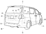
乗用車10はワンボックスタイプの乗用車であり、図1に示すように、後部にその乗用車10の背面開口部12を開閉するための跳ね上げ式の背面ドア14が設けられている。そして、背面ドア14の左右両側位置に複合ランプユニット20(リヤランプユニット20)の車幅方向内側半分を構成する第1ランプユニット30が取付けられている。また、乗用車10のボディ15には、背面開口部12の左右両側位置にリヤランプユニット20の車幅方向外側半分を構成する第2ランプユニット40が取付けられている。
ここで、右側のリヤランプユニット20は左側のリヤランプユニット20と左右対称に構成されている。
<About the rear section of passenger cars>
The
Here, the right
<リヤランプユニット20の概要について>
リヤランプユニット20は、図1、図2に示すように、後方から見た形状が略台形状をしたランプユニットであり、横に長い略角形の第1ランプユニット30と縦に長い略角形の第2ランプユニット40とがドア見切り位置17で合わせられるにより構成される。即ち、第1ランプユニット30と第2ランプユニット40は、背面ドア14が閉じられた状態でドア見切り位置17を介して連続するようになり、意匠的に一つのまとまりを持った略台形状のリヤランプユニット20を構成する。
<About the outline of the
As shown in FIGS. 1 and 2, the
<第1ランプユニット30について>
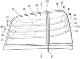
第1ランプユニット30は、図2、図3に示すように、表面側が開放されたランプハウジング32と、そのランプハウジング32の表面開放部を覆うアウタランプレンズ34とにより密閉容器状に形成されている。ランプハウジング32は、図4に示すように、ドア見切り位置17側(右端側)の側壁32wが浅く形成されている。そして、前記ランプハウジング32の浅い側壁32wの位置までアウタランプレンズ34のドア見切り位置17側(右端側)の側壁34wが奥方向に張出している。これにより、第1ランプユニット30の右端側から第2ランプユニット40の方向に光が漏れるようになる。
アウタランプレンズ34の内側には、前記ランプハウジング32の浅い側壁32wから表側に突出するように、インナランプレンズ35が配置されており、そのインナランプレンズ35の内側に棒状の導光体36がそのインナランプレンズ35の裏面に沿って横方向に延びるように設けられている。さらに、前記導光体36の裏側には、ランプハウジング32の表面開放部を塞ぐように板状の意匠部品であるエクステンション38が配置されている。
<About the
As shown in FIGS. 2 and 3, the
An
導光体36は、光源(LED37)の光を通し、さらにその光の一部を散乱させることでその導光体36の周囲を照らすための透明部材であり、図2に示すように、第1ランプユニット30の高さ方向における三箇所に設けられている。導光体36は、図5(B)に示すように、横断面形状が円形に構成されており、その導光体36の裏面側に光を散乱させるための略V字形の縦溝であるステップ36vが複数形成されている(図5(A)参照)。そして、図2、図3に示すように、各々の導光体36の左端位置に光源であるLED37が設置されている。各々のLED37は、光の照射方向が対応する導光体36の軸方向とほぼ一致するように位置決めされている。これにより、各々のLED37の光が対応する導光体36の軸方向に通るとともに、その光の一部が裏面側の前記ステップ36vに反射して散乱し、前記導光体36の周囲を照らすようになる。
また、インナランプレンズ35の右端位置には、図4、図5に示すように、導光体36を通過した光を集光して後記する第2ランプユニット40の導光体46に入射させるための凸レンズ35rが設けられている。
The
Further, as shown in FIGS. 4 and 5, the light that has passed through the
<第2ランプユニット40について>
第2ランプユニット40は、第1ランプユニット30と同様に、表面側が開放されたランプハウジング42と、そのランプハウジング42の表面開放部を覆うアウタランプレンズ44とにより密閉容器状に形成されている(図3参照)。ランプハウジング42は、図4に示すように、ドア見切り位置17側(左端側)の側壁42wが浅く形成されており、その側壁42wの位置までアウタランプレンズ44の左端側の側壁44wが奥方向に張出している。これにより、第2ランプユニット40から第1ランプユニット30側に光が漏れるようになる。
<About the
Similar to the
また、アウタランプレンズ44の内側には、前記ランプハウジング42の浅い側壁42wから表側に突出するように、インナランプレンズ45が配置されている。そして、前記インナランプレンズ45の内側に三本の棒状の導光体46が第1ランプユニット30における各導光体36の延長線上の位置に設けられている。第2ランプユニット40の導光体46は第1ランプユニット30の導光体36と等しい構成であり、各々の導光体46の右端位置に光源であるLED47が設置されている。各々のLED47は、光の照射方向が対応する導光体46の軸方向とほぼ一致するように位置決めされている。
さらに、インナランプレンズ45の左端位置には、図4に示すように、導光体46を通過した光を集光して第1ランプユニット30の導光体36に入射させる凸レンズ45rが設けられている。
なお、前記導光体46の裏側には、ランプハウジング42の表面開放部を塞ぐように板状の意匠部品であるエクステンション48が配置されている。
Further, an
Further, at the left end position of the
An
<リヤランプユニット20の動作について>
背面ドア14が閉じられた状態で第1ランプユニット30のLED37と第2ランプユニット40のLED47とが点灯すると、LED37,47の光が導光体36,46を通り、それらの導光体36,46のステップ36v,46vで散乱されることで前記導光体36,46の周囲を照らすようになる。さらに、図5(A)に示すように、第1ランプユニット30の導光体36の右端面36eから出た光はインナランプレンズ35の凸レンズ35rで集光され、第1ランプユニット30のアウタランプレンズ34、第2ランプユニット40のアウタランプレンズ44、及びインナランプレンズ45を通過して、第2ランプユニット40の導光体46に入射される。同様に、第2ランプユニット40の導光体46の左端面から出た光はインナランプレンズ45の凸レンズ45rで集光され、第2ランプユニット40のアウタランプレンズ44、第1ランプユニット30のアウタランプレンズ34、及びインナランプレンズ35を通過して、第1ランプユニット30の導光体36に入射される。
この結果、第1ランプユニット30の導光体36の右部分と第2ランプユニット40の導光体46の左部分との明るさがほぼ等しくなる。したがって、第1ランプユニット30と第2ランプユニット40との明るさがドア見切り位置17の近傍でばらつくことがなくなる。
<Operation of
When the
As a result, the brightness of the right part of the
<本実施形態に係るリヤランプユニット20の長所について>
本実施形態に係るリヤランプユニット20によると、第1ランプユニット30の導光体36を通過した光が第2ランプユニット40の導光体46まで到達し、第2ランプユニット40の導光体46を通過した光が第1ランプユニット30の導光体36まで到達可能なように構成されている。このため、第1ランプユニット30の導光体36と第2ランプユニット40の導光体46との明るさが均一化される。したがって、第1ランプユニット30と第2ランプユニット40との境界位置近傍で第1ランプユニット30と第2ランプユニット40との明るさがばらつくことがない。これにより、リヤランプユニット20の一体感が向上する。
また、第1ランプユニット30の導光体36の軸方向延長線上に第2ランプユニット40の導光体46が配置されて、第1ランプユニット30の導光体36の軸方向端面と第2ランプユニット40の導光体46の軸方向端面間で光が通過できるように構成されているため、両導光体間で光が通過し易くなる。
また、凸レンズ35r,45rにより光の向きを調整できるため、相手側の導光体36,46に対して効率的に光が届くようになる。
<Advantages of
According to the
Further, the
In addition, since the direction of light can be adjusted by the
<変更例>
なお、本発明は上記実施形態に限定されるものではなく、本発明の要旨を逸脱しない範囲における変更が可能である。例えば、本実施形態では、第1ランプユニット30と第2ランプユニット40とのアウタランプレンズ34,44の内側にインナランプレンズ35,45を設ける例を示したが、インナランプレンズ35,45を省略することも可能である。
また、本実施形態では、インナランプレンズ35,45に導光体36,46を通過した光の向きを調整する凸レンズ35r,45rを形成する例を示したが、前記凸レンズ35r,45rをアウタランプレンズ34,44の内側に設けることも可能である。さらに、前記レンズ35r,45rを導光体36,46の端面に形成することも可能である。
また、第1ランプユニット30と第2ランプユニット40との双方に凸レンズ35r,45rを設ける例を示したが、例えば、第2ランプユニット40側から第1ランプユニット30側に光を多く入射させたい場合には、第1ランプユニット30の凸レンズ35rを省略し、第2ランプユニット40側にのみ凸レンズ45rを設けることも可能である。
<Example of change>
In addition, this invention is not limited to the said embodiment, The change in the range which does not deviate from the summary of this invention is possible. For example, in the present embodiment, the example in which the
Further, in the present embodiment, the example is shown in which the
Moreover, although the example which provides the
14・・・・背面ドア
15・・・・ボディ
17・・・・ドア見切り位置
20・・・・リヤランプユニット(複合ランプユニット)
30・・・・第1ランプユニット
35r・・・凸レンズ
36・・・・導光体
40・・・・第2ランプユニット
45r・・・凸レンズ
46・・・・導光体
14 ···
30 ···
Claims (3)
前記第1ランプユニットと第2ランプユニットとは、光源の光を導光体に通すことでその導光体の周囲を照らせるように構成されており、
前記第1ランプユニットの導光体を通過した光が前記第2ランプユニットの導光体まで到達し、前記第2ランプユニットの導光体を通過した光が前記第1ランプユニットの導光体まで到達可能なように構成されていることを特徴とする乗用車の複合ランプユニット。 The first lamp unit provided at the door end and the second lamp unit provided at the body end are a composite lamp unit of a passenger car that constitutes a lamp unit having a single unit in design,
The first lamp unit and the second lamp unit are configured to illuminate the periphery of the light guide by passing light of the light source through the light guide.
The light passing through the light guide of the first lamp unit reaches the light guide of the second lamp unit, and the light passing through the light guide of the second lamp unit is the light guide of the first lamp unit. A composite lamp unit for a passenger car, characterized in that it can be reached up to
第1ランプユニットと第2ランプユニットとの導光体は棒状に形成されて、前記第1ランプユニットの導光体の軸方向延長線上に第2ランプユニットの導光体が配置されており、
前記第1ランプユニットの導光体の軸方向端面と第2ランプユニットの導光体の軸方向端面間を光が通過できるように構成されていることを特徴とする乗用車の複合ランプユニット。 A composite lamp unit for a passenger car according to claim 1,
The light guides of the first lamp unit and the second lamp unit are formed in a rod shape, and the light guide of the second lamp unit is disposed on the axial extension line of the light guide of the first lamp unit,
A composite lamp unit for a passenger car configured to allow light to pass between an axial end surface of the light guide of the first lamp unit and an axial end surface of the light guide of the second lamp unit.
前記第1ランプユニット、及び/又は、第2ランプユニットには、導光体を通過した光を集光してその光の向きを調整するレンズが設けられていることを特徴とする乗用車の複合ランプユニット。
A passenger car composite lamp unit according to claim 1 or 2,
The first lamp unit and / or the second lamp unit is provided with a lens that collects light that has passed through the light guide and adjusts the direction of the light. Lamp unit.
Priority Applications (2)
| Application Number | Priority Date | Filing Date | Title |
|---|---|---|---|
| JP2010272664A JP5526373B2 (en) | 2010-12-07 | 2010-12-07 | Passenger car composite lamp unit |
| PCT/JP2011/067591 WO2012077379A1 (en) | 2010-12-07 | 2011-08-01 | Combination lamp unit for passenger vehicle |
Applications Claiming Priority (1)
| Application Number | Priority Date | Filing Date | Title |
|---|---|---|---|
| JP2010272664A JP5526373B2 (en) | 2010-12-07 | 2010-12-07 | Passenger car composite lamp unit |
Publications (2)
| Publication Number | Publication Date |
|---|---|
| JP2012123977A true JP2012123977A (en) | 2012-06-28 |
| JP5526373B2 JP5526373B2 (en) | 2014-06-18 |
Family
ID=46206885
Family Applications (1)
| Application Number | Title | Priority Date | Filing Date |
|---|---|---|---|
| JP2010272664A Active JP5526373B2 (en) | 2010-12-07 | 2010-12-07 | Passenger car composite lamp unit |
Country Status (2)
| Country | Link |
|---|---|
| JP (1) | JP5526373B2 (en) |
| WO (1) | WO2012077379A1 (en) |
Cited By (15)
| Publication number | Priority date | Publication date | Assignee | Title |
|---|---|---|---|---|
| JP2014053151A (en) * | 2012-09-06 | 2014-03-20 | Koito Mfg Co Ltd | Vehicular lighting |
| JP2014067514A (en) * | 2012-09-25 | 2014-04-17 | Stanley Electric Co Ltd | Vehicular lighting fixture |
| JP2014107246A (en) * | 2012-11-30 | 2014-06-09 | Stanley Electric Co Ltd | Vehicle lighting fixture |
| JP2014123547A (en) * | 2012-11-21 | 2014-07-03 | Koito Mfg Co Ltd | Lighting tool for vehicle |
| WO2014112288A1 (en) * | 2013-01-17 | 2014-07-24 | トヨタ自動車株式会社 | Vehicle lamp structure |
| JP2014137924A (en) * | 2013-01-17 | 2014-07-28 | Toyota Motor Corp | Vehicle lamp structure |
| JP2015138709A (en) * | 2014-01-23 | 2015-07-30 | スタンレー電気株式会社 | vehicle lamp |
| JP2016012460A (en) * | 2014-06-27 | 2016-01-21 | 株式会社小糸製作所 | Vehicular lighting fixture |
| JP2016115558A (en) * | 2014-12-16 | 2016-06-23 | スタンレー電気株式会社 | Vehicular lighting unit |
| JP2016132297A (en) * | 2015-01-16 | 2016-07-25 | トヨタ自動車株式会社 | Vehicle lighting fixture structure |
| US9791123B2 (en) | 2015-01-21 | 2017-10-17 | Stanley Electric Co., Ltd. | Vehicle signal lamp |
| JP2018045769A (en) * | 2016-09-12 | 2018-03-22 | 株式会社小糸製作所 | Vehicular lighting fixture |
| US10589663B2 (en) | 2017-09-05 | 2020-03-17 | Ford Global Technologies, Llc | Method and apparatus for exterior rear lamp alignment |
| JP2020198272A (en) * | 2019-06-05 | 2020-12-10 | 株式会社今仙電機製作所 | Vehicle lamp fitting |
| JP7469634B2 (en) | 2020-05-13 | 2024-04-17 | 株式会社今仙電機製作所 | Vehicle lighting fixtures |
Families Citing this family (6)
| Publication number | Priority date | Publication date | Assignee | Title |
|---|---|---|---|---|
| JP6134484B2 (en) * | 2012-06-29 | 2017-05-24 | 株式会社小糸製作所 | Vehicle rear panel |
| TWI586563B (en) * | 2015-05-12 | 2017-06-11 | 曾瓊玉 | Tail lamp assembly for a vehicle |
| FR3047792B1 (en) * | 2016-02-16 | 2020-01-31 | Valeo Vision | LIGHTING AND / OR SIGNALING DEVICE FOR A MOTOR VEHICLE |
| FR3071450B1 (en) * | 2017-09-27 | 2022-04-01 | Psa Automobiles Sa | OPTICAL BLOCK WITH TWO COMPLEMENTARY PARTS OFFERING VISUAL AND FUNCTIONAL CONTINUITY OF THEIR CAVITIES |
| JP2020024791A (en) * | 2018-08-06 | 2020-02-13 | マツダ株式会社 | Vehicle lighting device |
| JP7360013B2 (en) | 2019-07-23 | 2023-10-12 | 株式会社今仙電機製作所 | ambient light |
Family Cites Families (2)
| Publication number | Priority date | Publication date | Assignee | Title |
|---|---|---|---|---|
| JPS5932841B2 (en) * | 1982-06-25 | 1984-08-11 | 日産車体株式会社 | Reflective rear combination lamp |
| EP2261083B8 (en) * | 2008-03-03 | 2013-09-25 | Fujikura, Ltd. | Door mirror device |
-
2010
- 2010-12-07 JP JP2010272664A patent/JP5526373B2/en active Active
-
2011
- 2011-08-01 WO PCT/JP2011/067591 patent/WO2012077379A1/en active Application Filing
Cited By (18)
| Publication number | Priority date | Publication date | Assignee | Title |
|---|---|---|---|---|
| JP2014053151A (en) * | 2012-09-06 | 2014-03-20 | Koito Mfg Co Ltd | Vehicular lighting |
| JP2014067514A (en) * | 2012-09-25 | 2014-04-17 | Stanley Electric Co Ltd | Vehicular lighting fixture |
| JP2016105420A (en) * | 2012-11-21 | 2016-06-09 | 株式会社小糸製作所 | Vehicle lighting appliance |
| JP2014123547A (en) * | 2012-11-21 | 2014-07-03 | Koito Mfg Co Ltd | Lighting tool for vehicle |
| JP2014107246A (en) * | 2012-11-30 | 2014-06-09 | Stanley Electric Co Ltd | Vehicle lighting fixture |
| WO2014112288A1 (en) * | 2013-01-17 | 2014-07-24 | トヨタ自動車株式会社 | Vehicle lamp structure |
| JP2014137925A (en) * | 2013-01-17 | 2014-07-28 | Toyota Motor Corp | Vehicle lamp structure |
| JP2014137924A (en) * | 2013-01-17 | 2014-07-28 | Toyota Motor Corp | Vehicle lamp structure |
| JP2015138709A (en) * | 2014-01-23 | 2015-07-30 | スタンレー電気株式会社 | vehicle lamp |
| JP2016012460A (en) * | 2014-06-27 | 2016-01-21 | 株式会社小糸製作所 | Vehicular lighting fixture |
| JP2016115558A (en) * | 2014-12-16 | 2016-06-23 | スタンレー電気株式会社 | Vehicular lighting unit |
| JP2016132297A (en) * | 2015-01-16 | 2016-07-25 | トヨタ自動車株式会社 | Vehicle lighting fixture structure |
| US9791123B2 (en) | 2015-01-21 | 2017-10-17 | Stanley Electric Co., Ltd. | Vehicle signal lamp |
| JP2018045769A (en) * | 2016-09-12 | 2018-03-22 | 株式会社小糸製作所 | Vehicular lighting fixture |
| US10589663B2 (en) | 2017-09-05 | 2020-03-17 | Ford Global Technologies, Llc | Method and apparatus for exterior rear lamp alignment |
| JP2020198272A (en) * | 2019-06-05 | 2020-12-10 | 株式会社今仙電機製作所 | Vehicle lamp fitting |
| JP7299483B2 (en) | 2019-06-05 | 2023-06-28 | 株式会社今仙電機製作所 | vehicle lamp |
| JP7469634B2 (en) | 2020-05-13 | 2024-04-17 | 株式会社今仙電機製作所 | Vehicle lighting fixtures |
Also Published As
| Publication number | Publication date |
|---|---|
| JP5526373B2 (en) | 2014-06-18 |
| WO2012077379A1 (en) | 2012-06-14 |
Similar Documents
| Publication | Publication Date | Title |
|---|---|---|
| JP5526373B2 (en) | Passenger car composite lamp unit | |
| US9457708B2 (en) | Vehicle lamp structure | |
| EP2524841A2 (en) | Vehicle lighting unit | |
| US20140003076A1 (en) | Vehicular lamp and window unit | |
| US9248776B2 (en) | Vehicular light unit with multiple light sources | |
| CN103836474A (en) | Motor vehicle light with light conductor and shield visible through light conductor | |
| JP6537834B2 (en) | Lighting device | |
| JP5733323B2 (en) | Vehicle lamp structure | |
| EP2957824B1 (en) | Vehicle lighting unit | |
| JP2014038733A (en) | Lamp for vehicle | |
| CN105841067A (en) | Multifunctional front fog lamp | |
| JP2016132297A (en) | Vehicle lighting fixture structure | |
| JP2015215946A (en) | Vehicular lighting tool | |
| JP2015505637A (en) | Device that uniformizes the appearance of motor vehicle signal light | |
| WO2014112289A1 (en) | Rear vehicle lamp structure | |
| TWI584977B (en) | Vehicle headlight lamp module, vehicle headlights, and vehicles | |
| JP2015069905A (en) | Vehicle lamp fitting | |
| JP6854113B2 (en) | Vehicle lighting | |
| JP6597024B2 (en) | Vehicle lighting | |
| JP2010100080A (en) | Light body for vehicle | |
| JP6706554B2 (en) | Vehicle lighting | |
| EP2518391A2 (en) | Vehicle lamp | |
| JP2016134342A (en) | Lighting device | |
| KR20150004587U (en) | Rear window spoiler | |
| JP6631053B2 (en) | Vehicle lighting |
Legal Events
| Date | Code | Title | Description |
|---|---|---|---|
| A621 | Written request for application examination |
Free format text: JAPANESE INTERMEDIATE CODE: A621 Effective date: 20130530 |
|
| TRDD | Decision of grant or rejection written | ||
| A01 | Written decision to grant a patent or to grant a registration (utility model) |
Free format text: JAPANESE INTERMEDIATE CODE: A01 Effective date: 20140311 |
|
| A61 | First payment of annual fees (during grant procedure) |
Free format text: JAPANESE INTERMEDIATE CODE: A61 Effective date: 20140324 |
|
| R150 | Certificate of patent or registration of utility model |
Ref document number: 5526373 Country of ref document: JP Free format text: JAPANESE INTERMEDIATE CODE: R150 |
|
| R250 | Receipt of annual fees |
Free format text: JAPANESE INTERMEDIATE CODE: R250 |
|
| R250 | Receipt of annual fees |
Free format text: JAPANESE INTERMEDIATE CODE: R250 |
|
| R250 | Receipt of annual fees |
Free format text: JAPANESE INTERMEDIATE CODE: R250 |
|
| R250 | Receipt of annual fees |
Free format text: JAPANESE INTERMEDIATE CODE: R250 |
|
| R250 | Receipt of annual fees |
Free format text: JAPANESE INTERMEDIATE CODE: R250 |
|
| R250 | Receipt of annual fees |
Free format text: JAPANESE INTERMEDIATE CODE: R250 |
|
| R250 | Receipt of annual fees |
Free format text: JAPANESE INTERMEDIATE CODE: R250 |
|
| R250 | Receipt of annual fees |
Free format text: JAPANESE INTERMEDIATE CODE: R250 |