JP2012123797A - Integrate-and-fire electronic neurons, method and program - Google Patents
Integrate-and-fire electronic neurons, method and program Download PDFInfo
- Publication number
- JP2012123797A JP2012123797A JP2011260006A JP2011260006A JP2012123797A JP 2012123797 A JP2012123797 A JP 2012123797A JP 2011260006 A JP2011260006 A JP 2011260006A JP 2011260006 A JP2011260006 A JP 2011260006A JP 2012123797 A JP2012123797 A JP 2012123797A
- Authority
- JP
- Japan
- Prior art keywords
- membrane potential
- neuron
- inhibitory
- spike
- response
- Prior art date
- Legal status (The legal status is an assumption and is not a legal conclusion. Google has not performed a legal analysis and makes no representation as to the accuracy of the status listed.)
- Granted
Links
Images
Classifications
-
- G—PHYSICS
- G06—COMPUTING; CALCULATING OR COUNTING
- G06N—COMPUTING ARRANGEMENTS BASED ON SPECIFIC COMPUTATIONAL MODELS
- G06N3/00—Computing arrangements based on biological models
- G06N3/02—Neural networks
- G06N3/04—Architecture, e.g. interconnection topology
- G06N3/049—Temporal neural networks, e.g. delay elements, oscillating neurons or pulsed inputs
Landscapes
- Engineering & Computer Science (AREA)
- Theoretical Computer Science (AREA)
- Physics & Mathematics (AREA)
- General Health & Medical Sciences (AREA)
- Computing Systems (AREA)
- Biomedical Technology (AREA)
- Biophysics (AREA)
- Computational Linguistics (AREA)
- Data Mining & Analysis (AREA)
- Evolutionary Computation (AREA)
- Life Sciences & Earth Sciences (AREA)
- Molecular Biology (AREA)
- Artificial Intelligence (AREA)
- General Engineering & Computer Science (AREA)
- General Physics & Mathematics (AREA)
- Mathematical Physics (AREA)
- Software Systems (AREA)
- Health & Medical Sciences (AREA)
- Semiconductor Memories (AREA)
- Measurement And Recording Of Electrical Phenomena And Electrical Characteristics Of The Living Body (AREA)
- Feedback Control In General (AREA)
Abstract
Description
本発明は、米国防総省国防高等研究計画局(DARPA)によって授与された契約第HR0011−09−C−0002号に基づく政府支援により行われたものである。米国政府は本発明において一定の権利を有する。 This invention was made with government support under Contract No. HR0011-09-C-0002 awarded by the US Department of Defense Advanced Research Projects Agency (DARPA). The US government has certain rights in this invention.
本発明は、一般に、ニューロン・シナプス型システムに関し、より具体的には、スパイクタイミング依存可塑性に基づくニューロン・シナプス型システムに関する。 The present invention relates generally to neuron-synaptic systems, and more specifically to neuron-synaptic systems based on spike timing dependent plasticity.
生物システムは、感覚入力によって提供された情報に秩序を与える。この情報は、典型的に、特有の空間的および時間的構造を備えた局部的イベントを含む時空パターンの形で提供される。これらのイベントは多種多様な空間時間スケールで発生するが、脳などの生物システムは、それらを統合し複数個の関連情報を抽出することができる。このような生物システムは、雑音のある時空入力から信号を急速に抽出することができる。 Biological systems give order to the information provided by sensory input. This information is typically provided in the form of a spatio-temporal pattern that includes local events with distinct spatial and temporal structures. These events occur on a wide variety of spatio-temporal scales, but biological systems such as the brain can integrate them and extract a plurality of related information. Such biological systems can rapidly extract signals from noisy space-time inputs.
生物システムでは、ニューロンの軸索と他のニューロンの樹状突起との間の接触点はシナプスと呼ばれる。そのシナプスに関する2つのニューロンはそれぞれ、前シナプスおよび後シナプスと呼ばれる。ニューロンは、シナプスを介して受信した十分な入力によって活動化されると、そのニューロンが前シナプスであるシナプスに対して送達される「スパイク」を放出する。ニューロンは「興奮性」または「抑制性」のいずれかにすることができる。シナプス・コンダクタンスは、シナプスが前シナプスのスパイクによって活動化されたときにシナプスがその後シナプス・ターゲットに及ぼす影響の量を示す尺度である。シナプス・コンダクタンスは、スパイクタイミング依存可塑性(spike-timing dependent plasticity、STDP)により、前シナプス・ニューロンと後シナプス・ニューロンの相対スパイク時間の関数として時間とともに変化することができる。STDP規則では、その前シナプス・ニューロンが発火した後でその後シナプス・ニューロンが発火する場合にシナプスのコンダクタンスが増加し、2回の発火(fire)の順序が逆になった場合にシナプスのコンダクタンスが減少する。我々の個々の経験は、脳全体にわたる何兆ものシナプスのコンダクタンスとして保管されている。 In biological systems, the point of contact between a neuron's axon and the dendrites of other neurons is called a synapse. The two neurons associated with that synapse are called the presynapse and the postsynapse, respectively. When a neuron is activated by sufficient input received through the synapse, it releases a “spike” that is delivered to the presynaptic synapse. Neurons can be either “excitable” or “inhibitory”. Synaptic conductance is a measure of the amount of influence a synapse has on a subsequent synaptic target when the synapse is activated by a presynaptic spike. Synaptic conductance can change over time as a function of the relative spike times of pre- and post-synaptic neurons due to spike-timing dependent plasticity (STDP). In the STDP rule, the synaptic conductance increases when the presynaptic neuron fires and then the synaptic neuron fires, and the synaptic conductance increases when the order of the two fires is reversed. Decrease. Our individual experiences are stored as trillions of synaptic conductances throughout the brain.
人工ニューラル・ネットワークとも呼ばれるニューロン・シナプス型システムは、電子システムが本質的に生物学的脳と類似した方法で機能できるようにする計算システムである。ニューロン・シナプス型システムは、生物学的脳のニューロンと機能的にほぼ同等である処理要素間の接続を作成する。ニューロン・シナプス型システムは、生物ニューロンを手本にした様々な電子回路を含むことができる。 A neuron-synaptic system, also called an artificial neural network, is a computational system that allows an electronic system to function in a manner essentially similar to a biological brain. Neuron-synaptic systems create connections between processing elements that are approximately functionally equivalent to neurons in the biological brain. Neuron-synaptic systems can include various electronic circuits modeled on biological neurons.
本発明の諸実施形態は、統合発火型電子ニューロンを提供する。 Embodiments of the present invention provide an integrated firing electronic neuron.
一実施形態では、外部スパイク信号を受信したことに応じて、外部スパイク信号に基づいて、ニューロン膜電位を表すデジタル・カウンタが更新される。膜電位は漏れ率に基づいて減衰される。膜電位がしきい値を超えしたことに応じて、スパイク信号が生成される。膜電位は生物ニューロン内の膜電位(電圧)に対応する。 In one embodiment, in response to receiving the external spike signal, a digital counter representing the neuron membrane potential is updated based on the external spike signal. The membrane potential is attenuated based on the leakage rate. A spike signal is generated in response to the membrane potential exceeding the threshold. The membrane potential corresponds to the membrane potential (voltage) in the biological neuron.
他の実施形態では、混合モードのデジタル・アナログ電子ニューロンが提供され、外部興奮性スパイク信号を受信したことに応じて、変更する必要があるカウンタ内のビットのみが変更されるようなビット単位の操作を使用して増加分だけデジタル膜電位が増分される。さらに、外部抑制性スパイク信号を受信したことに応じて、変更する必要があるカウンタ内のビットのみが変更されるようなビット単位の操作を使用して減少分だけ膜電位が減分される。さらに、アナログ抵抗−容量モデル(analog resistor-capacitor model)を使用して時定数に基づいて膜電位が減衰される。 In other embodiments, a mixed-mode digital-analog electronic neuron is provided, and in response to receiving an external excitatory spike signal, only the bits in the counter that need to be changed are changed bit-by-bit. Using the operation, the digital membrane potential is incremented by an increment. Further, in response to receiving an external inhibitory spike signal, the membrane potential is decremented by a decrement using a bit-by-bit operation in which only the bits in the counter that need to be changed are changed. In addition, the membrane potential is attenuated based on the time constant using an analog resistor-capacitor model.
一実施形態では、1つの時間ステップで受信した興奮性スパイク信号の数にスケーリング・パラメータを掛けたものに等しい増加分だけ膜電位を増加する。一例では、スケーリング・パラメータは2の倍数に制限され、受信した興奮性スパイクの数に倍率でスケーリングする(倍率を掛ける)ことがビットシフト操作によって行われるようになっている。 In one embodiment, the membrane potential is increased by an increment equal to the number of excitatory spike signals received in one time step multiplied by the scaling parameter. In one example, the scaling parameter is limited to a multiple of 2, so that the number of received excitatory spikes is scaled (multiplied) by a bit shift operation.
一実施形態では、1つの時間ステップで受信した抑制性スパイクの数にスケーリング・パラメータを掛けたものに等しい減少分だけ膜電位を減少させる。スケーリング・パラメータは2の倍数に制限され、受信した抑制性スパイクの数に倍率を掛けることがビットシフト操作によって行われるようになっている。 In one embodiment, the membrane potential is decreased by a decrease equal to the number of inhibitory spikes received in one time step multiplied by the scaling parameter. The scaling parameter is limited to a multiple of 2, so that the number of received inhibitory spikes is multiplied by a bit shift operation.
他の実施形態では、イベント・ドリブン電子ニューロンが提供され、興奮性イベント・タイプが発生すると、デジタル膜電位は興奮性シナプス強度増加分だけ増分される。抑制性イベント・タイプが発生すると、デジタル膜電位は抑制性シナプス強度減少分だけ減分される。減衰イベント・タイプが発生すると、デジタル膜電位は漏れ強度減少分だけ減分される。 In other embodiments, when an event-driven electronic neuron is provided and an excitatory event type occurs, the digital membrane potential is incremented by an increase in excitatory synaptic strength. When an inhibitory event type occurs, the digital membrane potential is decremented by the inhibitory synaptic strength reduction. When the decay event type occurs, the digital membrane potential is decremented by a decrease in leak strength.
本発明の上記その他の特徴、態様、および利点は、以下の説明、特許請求の範囲、および添付図面に関連して十分理解されたものになるであろう。 These and other features, aspects, and advantages of the present invention will become better understood with reference to the following description, appended claims, and accompanying drawings.
本発明の諸実施形態は、統合発火型ニューロンを含むニューロン・シナプス型システムを提供する。統合発火型電子ニューロン(integrate and fire electronic neuron)は、生物ニューロンで検出された統合およびスパイク特性をシミュレートする計算効率の良いメカニズムである。このような電子ニューロンは、シナプス入力を膜電位電圧変数に統合し、膜電位電圧がしきい値を超えた場合にスパイクおよび電圧リセットを発生することによって動作する。本発明の諸実施形態は、正確な1対1のソフトウェア・ハードウェア対応を可能にし、カスタム・デジタル回路内のソフトウェア・シミュレーションおよびハードウェア・シミュレーションで実装可能な漏出型の統合発火型ニューロン・モデルをさらに提供する。 Embodiments of the present invention provide a neuron-synaptic system that includes integrated firing neurons. The integrated and fire electronic neuron is a computationally efficient mechanism that simulates the integration and spike characteristics detected in biological neurons. Such electronic neurons operate by integrating synaptic inputs into membrane potential voltage variables and generating spikes and voltage resets when the membrane potential voltage exceeds a threshold. Embodiments of the present invention enable leaky integrated firing neuron models that allow for accurate one-to-one software hardware support and can be implemented with software and hardware simulation within custom digital circuits. Provide further.
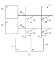
次に図1を参照すると、本発明の一実施形態による、統合発火型電子ニューロンを相互接続するクロスバー・アレイを有するニューロン・シナプス型システム10の図が示されている。一例では、クロスバー・アレイは、約0.1nm〜10μmの範囲内のピッチを有することができる超高密度クロスバー・アレイを含むことができる。ニューロン・シナプス型システム10は、本発明の一実施形態による、複数の統合発火型ニューロン14、16、18、および20を有するクロスバー・アレイ12を含む。これらのニューロンは本明細書では「電子ニューロン」とも呼ばれる。ニューロン14および16は軸索ニューロンであり、ニューロン18および20は樹状突起ニューロンである。
Referring now to FIG. 1, a diagram of a neuron-
軸索ニューロン14および16は、出力22および24が導電性軸索パス/ワイヤ(軸索)26および28にそれぞれ接続された状態で示されている。樹状突起ニューロン18および20は、入力30および32が導電性樹状突起パス/ワイヤ(樹状突起)34および36にそれぞれ接続された状態で示されている。軸索ニューロン14および16は、入力も含み、樹状突起伝いで信号を受信するが、これらの入力および樹状突起は図を単純にするために図示されていない。したがって、軸索ニューロン14および16は、樹状突起接続伝いで入力を受信するときに、樹状突起ニューロンとして機能することになる。同様に、樹状突起ニューロン18および20は、その軸索接続伝いで信号を送出するときに、軸索ニューロンとして機能することになる。ニューロン14、16、18、および20のいずれかが発火したときに、そのニューロンはその軸索接続および樹状突起接続にパルスを送出することになる。本明細書で使用する「ときに(when)」という用語は、ニューロンが発火してから即座にまたはニューロンが発火してからある程度の期間後に、信号が送信されることを意味することができる。
軸索26、28と樹状突起34、36との間の各接続はシナプス・デバイス(synapse device)によって行われ、そのシナプス・デバイスは一実施形態では可変状態抵抗(variable state resistor)38、40、42、および44を含む。可変状態抵抗が位置する接合部は、本明細書では「クロスポイント接合部(cross-point junction)」と呼ぶことができる。「可変状態抵抗」という用語は、電気パルス(電圧または電流のいずれか一方)の印加によってデバイスの電気コンダクタンス特性が変化するクラスのデバイスを指す。クロスバー・アレイ・ニューロン・シナプス型システムならびにこのようなクロスバー・アレイで使用される可変状態抵抗について全般的に考察するために、2008年発行のJ. Nanoelectronics andOptoelectronics, 2008の第3巻、203〜230ページに掲載されたK.Likharevによる「Hybrid CMOS/Nanoelectronic Circuits: Opportunities andChallenges」を参照する。本発明の一実施形態では、可変状態抵抗は相変化メモリ(PCM)を含むことができる。PCMデバイスの他に、本発明の諸実施形態で使用可能なその他の可変状態抵抗デバイスとしては、上記で参照したK.Likharevによる論文により詳細に記載されているように、金属酸化物、硫化物、酸化シリコンおよびアモルファスシリコン、磁気トンネル接合、浮遊ゲートFETトランジスタ、および有機薄膜層デバイスを使用して作られたデバイスを含む。また、可変状態抵抗は、スタティック・ランダム・アクセス・メモリ・デバイスを使用して構築することもできる。また、可変状態抵抗にはアクセス・デバイス39も付加され、このアクセス・デバイスは、PNダイオード、ダイオードとして配線されたFET、または非線形の電圧電流応答を有するその他の何らかのエレメントを含むことができる。
Each connection between
一般に、本発明の一実施形態により、軸索ニューロン14および16は、樹状突起入力接続(図示せず)から受信する入力がしきい値を超えたときに、「発火する」(パルスを送信または放出する)ことになる。軸索ニューロン14および16が発火すると、それらは、時間の経過につれて(たとえば、約50msec)減衰するA−STDP変数を維持する。A−STDP変数は、たとえば、指数関数、一次関数、多項式関数、または二次関数などの関数に応じて、時間の関数として減衰する。A−STDP変数はサンプリングすることができる。本発明の他の実施形態では、A−STDP変数は、時間の経過につれて減少する代わりに増加することもできる。
In general, according to one embodiment of the present invention,
A−STDP変数は、関連のニューロンの最後の発火以降の時間をエンコードすることにより、軸索STDPを達成するために使用される。軸索STDPは、典型的に、このコンテキストでシナプス・コンダクタンスを増加することとして定義される「増強(potentiation)」を制御するために使用されるが、このコンテキストでシナプス・コンダクタンスを減少させることを指す「下降(depression)」を制御するために使用することもできる。樹状突起ニューロン18、20が発火すると、それらは、時間の経過につれて(たとえば、約50msec)減衰するD−STDP変数を維持する。D−STDP変数は、たとえば、指数関数、一次関数、多項式関数、または二次関数などの関数に応じて、時間の関数として減衰する。D−STDP変数はサンプリングすることができる。本発明の他の実施形態では、この変数は、時間の経過につれて減少する代わりに増加することもできる。
The A-STDP variable is used to achieve axon STDP by encoding the time since the last firing of the relevant neuron. Axon STDP is typically used to control “potentiation” which is defined as increasing synaptic conductance in this context, but in this context it is used to reduce synaptic conductance. It can also be used to control "depression" pointing. As the
D−STDP変数は、以下により詳細に論ずるように、関連のニューロンの最後の発火以降の時間をエンコードすることにより、樹状突起STDPを達成するために使用することができる。樹状突起STDPは、典型的に、このコンテキストでシナプス・コンダクタンスを減少させることとして定義される「下降」を制御するために使用されるが、このコンテキストでシナプス・コンダクタンスを増加することを指す「増強」を制御するために使用することもできる。 The D-STDP variable can be used to achieve dendritic STDP by encoding the time since the last firing of the relevant neuron, as discussed in more detail below. Dendritic STDP is typically used to control “down” defined as decreasing synaptic conductance in this context, but refers to increasing synaptic conductance in this context. It can also be used to control “enhancement”.
一実施形態では、本発明は、デジタル回路を使用して実装される統合発火型電子ニューロンを提供する。第1の実装例は、線形漏れ回路と線形ポイント電流(linear point-current)タイプのシナプス・デバイスを使用する、統合発火型ニューロンを含む。第2の実装例は、線形漏れ回路を凸状電圧減衰回路で置き換えることを含み、さらに不応期を使用する。第3の実装例は、コンダクタンスベースの抑制を追加することを含む。第4の実装例は、二重指数コンダクタンスベースのシナプスを実装する。これらの実装例については以下により詳細に説明する。 In one embodiment, the present invention provides an integrated firing electronic neuron implemented using digital circuitry. The first implementation includes an integrated firing neuron that uses a linear leakage circuit and a linear point-current type synaptic device. A second implementation includes replacing the linear leakage circuit with a convex voltage decay circuit and further uses a refractory period. A third implementation includes adding conductance-based suppression. The fourth implementation example implements a double exponential conductance based synapse. These implementation examples are described in more detail below.
線形漏れ統合発火型(LL−IF)
本発明の第1の実装例は、図5のブロック図例によって示されているように、線形漏れ統合発火型(LL−IF)電子ニューロン80を含む。LL−IFニューロン80によって受信された各興奮性スパイクについて、入力積分器モジュール81は一定の量s+だけニューロンの膜電位Vを増加し、ニューロンが受信する各抑制性スパイクについて、入力積分器モジュール81は一定の量s-だけVを減少させる。ニューロン膜漏れは、漏出器(leaker)モジュール82を使用して各時間ステップ内でλだけVを線形に減少させることによってシミュレートされる。1つのデジタル・クロック信号は複数の時間ステップを提供する。比較器モジュール83により、ニューロン80への入力がしきい値θより上にVを増加する場合、スパイクが生成され、Vがリセット値Vresetに設定される。
Linear leak integrated ignition type (LL-IF)
A first implementation of the present invention includes a linear leak integrated firing (LL-IF)
ニューロン・パラメータは非負整数であり、n+は1つの時間ステップ内で受信した興奮性スパイクの数であり(整数[0,63])、n-は1つの時間ステップ内で受信した抑制性スパイクの数であり(整数[0,63])、s+は∈{0,1,2,4,8,16,32}である興奮強度であり、s-は∈{0,1,2,4,8,16,32}である抑制強度であり、効率のために、s+およびs-は2の累乗になるように制限されており、θはVと同じ分解能を有する整数であるスパイクしきい値であり、Vresetはリセット電圧であり(単純にするため、Vreset=0と想定されている)、λは漏れ率である(整数[0,63])。 The neuron parameter is a non-negative integer, n + is the number of excitatory spikes received within one time step (integer [0, 63]), and n − is the inhibitory spike received within one time step. (Integer [0, 63]), s + is the excitement intensity ∈ {0, 1, 2, 4, 8, 16, 32}, and s − is ∈ {0, 1, 2, 4,8,16,32}, and for efficiency, s + and s − are limited to powers of 2 and θ is an integer with the same resolution as V It is a threshold, V reset is the reset voltage (for simplicity, it is assumed that V reset = 0), and λ is the leakage rate (integer [0, 63]).
ニューロン・ダイナミクスに関しては、Vはデジタル・カウンタによって維持される膜電圧(8ビットで表される非負整数)であり、Vは折り返さず、Vがすでにゼロである場合にV−1は依然としてゼロになる。Vに関する更新規則は、以下の式に応じてVを更新することを含む。
V(t)=V(t−1)−λ+s+n+−s-n-
ここで、s+は+s+n+がn+のビットシフト加算になるような2の累乗である。さらに、s-は−s-n-がn-のビットシフト減算になるような2の累乗である。
For neuron dynamics, V is the membrane voltage maintained by the digital counter (a non-negative integer represented by 8 bits), V does not wrap, and V-1 is still zero when V is already zero. Become. The update rule for V includes updating V according to the following equation:
V (t) = V (t−1) −λ + s + n + −s − n −
Here, s + is a power of 2 such that + s + n + is a bit shift addition of n + . Furthermore, s − is a power of 2 such that −s − n − is a bit shift subtraction of n − .
このニューロンに関するスパイク条件は以下のものを含む。
V(t)>θである場合、V(t)=Vresetを設定し、スパイクを放出する。
The spike conditions for this neuron include:
If V (t) > θ, set V (t) = V reset and release the spike.
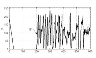
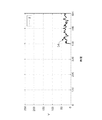
図2は、時間に関して、入力なし(0〜200時間ステップ)、確率興奮性入力(201〜400時間ステップ)、および確率興奮性抑制性入力(401〜600時間ステップ)という条件に対するLL−IF電子ニューロンのV変数の応答グラフ例51を示している。各時間ステップ内の入力スパイクの数はガウス分布(μ=1,δ=1)から引き出され、負数はゼロに丸められている。各時間ステップの長さはデジタル・クロック信号によって決定される。1msecの時間ステップは、生物ニューロンで検出されたものを近似する時間スケール上での挙動を生成する。使用されるパラメータ値は、s+=24、s-=23、θ=200、Vreset=0、λ=6である。 FIG. 2 shows LL-IF electrons for the conditions of no input (0-200 hour steps), stochastic excitatory input (201-400 hour steps), and stochastic excitatory inhibitory input (401-600 hour steps) with respect to time. The response graph example 51 of the V variable of a neuron is shown. The number of input spikes in each time step is derived from a Gaussian distribution (μ = 1, δ = 1), and negative numbers are rounded to zero. The length of each time step is determined by the digital clock signal. A time step of 1 msec produces a behavior on a time scale that approximates that detected by biological neurons. The parameter values used are s + = 2 4 , s − = 2 3 , θ = 200, V reset = 0, λ = 6.
不応期付き凸状減衰統合発火型(CD−IF w/RP)
本発明の第2の実装例は、図6のブロック図例によって示されているように、不応期付き凸状減衰近似統合発火型(CD−IF w/RP)電子ニューロン85を含む。CD−IF w/RP電子ニューロン85は不応期を有し、ニューロンが受信する各興奮性スパイクについて、入力積分器86は一定の量s+だけ膜電位Vを増加し、ニューロンが受信する各抑制性スパイクについて、入力積分器86は一定の量s-だけVを減少させる。ニューロン膜漏れは、漏出器モジュール87が各時間ステップ内で時定数τに応じてVを減衰することによってシミュレートされる(したがって、静止膜電位が0であると想定する)。比較器モジュール88により、ニューロンへの入力がしきい値θより上にVを増加する場合、ニューロンはスパイクを生成し、VがVresetに設定される。ニューロンがスパイクを生成すると、不応期発生器モジュール89がρ時間ステップの間、VをVresetに保持することによって不応期がシミュレートされる。
Convex decay integrated ignition type with refractory period (CD-IF w / RP)
A second implementation of the present invention includes a convex decay approximate integrated firing (CD-IF w / RP)
すべてのニューロン・パラメータは非負整数であり、n+は1つの時間ステップ内で受信した興奮性スパイクの数であり(整数[0,63])、n-は1つの時間ステップ内で受信した抑制性スパイクの数であり(整数[0,63])、s+は∈{0,1,2,4,8,16,32,64,128}である興奮強度であり、s-は∈{0,1,2,4,8,16,32,64,128}である抑制強度であり、効率のために、s+およびs-は2の累乗になるように制限されており、θはスパイクしきい値(Vと同じ分解能を有する整数)であり、Vresetはリセット電圧であって、θより小さい任意の正整数にすることができ、τは∈{1,2,4,8...210}である膜時定数であり、効率のために、τはVの範囲内の2の累乗になるように制限されており、ρは不応期である(整数[0,63])。本明細書に示されているパラメータ範囲は例に過ぎない。当業者であれば、本発明の諸実施形態では複数のパラメータ範囲が可能であり有用であることを認識するであろう。 All neuron parameters are non-negative integers, n + is the number of excitatory spikes received within one time step (integer [0, 63]), and n − is the suppression received within one time step. Is the number of sex spikes (integer [0, 63]), s + is the excitement intensity ∈ {0, 1, 2, 4, 8, 16, 32, 64, 128}, and s − is ∈ { 0, 1, 2, 4, 8, 16, 32, 64, 128}, and for efficiency, s + and s − are limited to powers of 2, and θ is Spike threshold (an integer with the same resolution as V), V reset is the reset voltage and can be any positive integer less than θ, and τ is ∈ {1, 2, 4, 8,. . . 2 10 }, for efficiency, τ is limited to be a power of 2 in the range of V, and ρ is the refractory period (integer [0, 63]). The parameter ranges shown herein are only examples. One skilled in the art will recognize that multiple parameter ranges are possible and useful in embodiments of the present invention.
ニューロン・ダイナミクスに関しては、Vは膜電位カウンタ(10ビットで表される非負整数)であり、Vは折り返さず、Vがすでにゼロである場合にV−1は依然としてゼロになる。rは不応期カウンタ(6ビットで表される正整数)であり、rは折り返さない。 For neuron dynamics, V is a membrane potential counter (a non-negative integer represented by 10 bits), V does not wrap around, and V-1 is still zero when V is already zero. r is a refractory period counter (a positive integer represented by 6 bits), and r does not wrap around.
更新規則は、以下のものを含む。
r(t)>0である場合、r(t)=r(t−1)−1であり、Vを更新せず、
さもなければ、
に応じてVを更新する。
ここで、s+は+s+n+がn+のビットシフト加算になるような2の累乗である。さらに、s-は−s-n-がn-のビットシフト減算になるような2の累乗である。さらに、τは−V(t−1)/τがV(t−1)のビットシフト減算になるような2の累乗である。
The update rules include the following:
If r (t)> 0, then r (t) = r (t−1) −1, V is not updated,
Otherwise,
V is updated accordingly.
Here, s + is a power of 2 such that + s + n + is a bit shift addition of n + . Furthermore, s − is a power of 2 such that −s − n − is a bit shift subtraction of n − . Furthermore, τ is a power of 2 such that −V (t−1) / τ is a bit shift subtraction of V (t−1).
このニューロンに関するスパイク条件は以下のものを含む。
V(t)>θである場合、r(t)=ρを設定し、スパイクを放出する。
The spike conditions for this neuron include:
If V (t) > θ, set r (t) = ρ and emit a spike.
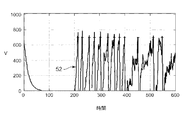
図3は、入力なし(たとえば、0〜200時間ステップ)、確率興奮性入力(たとえば、201〜400時間ステップ)、および確率興奮性抑制性入力(たとえば、401〜600時間ステップ)に対するCD−IF w/RP電子ニューロンの応答グラフ例52を示している。各時間ステップ内の入力スパイクの数はガウス分布(μ=1,δ=1)から引き出され、負数はゼロに丸められている。使用されるパラメータ値は、s+=26、s-=25、θ=700、Vreset=0、ρ=8、およびτ=16である。
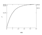
FIG. 3 shows CD-IF for no input (eg, 0-200 hour steps), stochastic excitatory input (eg, 201-400 hour steps), and stochastic excitatory inhibitory input (eg, 401-600 hour steps). The
不応期およびコンダクタンスベースの抑制付き凸状減衰統合発火型(CD−IF w/RP&CB−I)
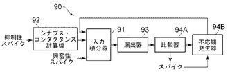
本発明の第3の実装例は、図7のブロック図例によって示されているように、不応期およびコンダクタンスベースの抑制付き凸状減衰近似統合発火型(CD−IF w/RP&CB−I)電子ニューロン90を含む。CD−IF w/RP&CB−Iニューロン90が受信する各興奮性スパイクについて、入力積分器モジュール91は一定の量s+だけ膜電位Vを増加し、入力積分器モジュール91によって受信された各抑制性スパイクについて、入力積分器モジュール91は一定の量s-だけ抑制性チャネル・コンダクタンスgを増加する。シナプス・コンダクタンス計算器モジュール92は各時間ステップで抑制性チャネル・コンダクタンス減衰を提供し、率は時定数τgによって支配される。次に、以下のように膜電位Vを減少させることにより、各時間ステップで入力積分器モジュール91によって抑制が膜電位に統合される。
ここで、gscaleはgの倍率である(これは0という抑制性逆転電位を想定している)。膜漏れは、漏出器モジュール93が各時間ステップ内で時定数τに応じてVを減衰することによってシミュレートされる(したがって、静止膜電位が0であると想定する)。比較器モジュール94Aにより、ニューロンへの入力がしきい値θより上にVを増加する場合、ニューロンはスパイクを生成し、VがVresetに設定される。不応期発生器モジュール94Bにより、ニューロンがスパイクを生成すると、ρ時間ステップの間、VをVresetに保持することによって不応期がシミュレートされる。
Convex damped integrated ignition type with refractory period and conductance-based suppression (CD-IF w / RP & CB-I)
A third implementation of the present invention is a convex damped approximate integrated firing (CD-IF w / RP & CB-I) electron with refractory period and conductance based suppression, as illustrated by the block diagram example of FIG.
Here, g scale is the magnification of g (this assumes an inhibitory reversal potential of 0). Membrane leakage is simulated by the
すべてのパラメータは非負整数であり、n+は1つの時間ステップ内で受信した興奮性スパイクの数であり(整数[0,63])、n-は1つの時間ステップ内で受信した抑制性スパイクの数であり(整数[0,63])、s+は∈{0,1,2,4,8,16,32,64,128}である興奮強度であり、s-は∈{0,1,2,4,8,16,32,64,128}である抑制強度であり、効率のために、s+およびs-は2の累乗になるように制限されており、θはスパイクしきい値(Vと同じ分解能を有する整数)であり、Vresetはリセット電圧であって、θより小さい任意の正整数にすることができ、τは∈{1,2,4,8...210}である膜時定数であり、効率のために、τはVの範囲内の2の累乗になるように制限されており、τgは∈{1,2,4,8...28}である抑制性コンダクタンス時定数であり、効率のために、τgはgの範囲内の2の累乗になるように制限されており、ρは不応期であり(整数[0,63])、gscaleはgの区分倍率(divisive scaling factor)である(整数[10,16])。本明細書に示されているパラメータ範囲は例に過ぎない。当業者であれば、本発明の諸実施形態では複数のパラメータ範囲が可能であり有用であることを認識するであろう。 All parameters are non-negative integers, n + is the number of excitatory spikes received within one time step (integer [0, 63]), and n − is an inhibitory spike received within one time step. (Integer [0, 63]), s + is the excitement intensity ∈ {0, 1, 2, 4, 8, 16, 32, 64, 128}, and s − is ∈ {0, 1, 2, 4, 8, 16, 32, 64, 128}, and for efficiency, s + and s − are limited to powers of 2, and θ spikes. Threshold (an integer with the same resolution as V), V reset is the reset voltage and can be any positive integer less than θ, and τ is ∈ {1, 2, 4, 8,. . . 2 10 }, for efficiency, τ is limited to be a power of 2 in the range of V, and τ g is ∈ {1, 2, 4, 8,. . . 2 8 } is an inhibitory conductance time constant, for efficiency, τ g is limited to be a power of 2 within g, and ρ is a refractory period (integer [0, 63 ], G scale is the diversive scaling factor of g (integer [10, 16]). The parameter ranges shown herein are only examples. One skilled in the art will recognize that multiple parameter ranges are possible and useful in embodiments of the present invention.
ダイナミクスに関しては、Vは膜電圧カウンタ(10ビットで表される非負整数)であり、Vは折り返さず、Vがすでにゼロである場合にV−1は依然としてゼロになる。rは不応期カウンタ(6ビットで表される正整数)であり、rは折り返さない。gは抑制性コンダクタンス(10ビットで表される正整数)であり、gは折り返さない。 With respect to dynamics, V is a membrane voltage counter (a non-negative integer represented by 10 bits), V does not wrap around, and V-1 is still zero when V is already zero. r is a refractory period counter (a positive integer represented by 6 bits), and r does not wrap around. g is an inhibitory conductance (a positive integer represented by 10 bits), and g does not turn.
このニューロンに関する更新規則は、以下のものを含む。
ここで、τgは2の累乗であり、−g(t−1)/τgはg(t−1)のビットシフト減算であり、s-は2の累乗であり、−s-n-はn-のビットシフト減算である。
The update rules for this neuron include:
Where τ g is a power of 2, −g (t−1) / τ g is a bit shift subtraction of g (t−1), s − is a power of 2, and −s − n −. Is a bit shift subtraction of n − .
r(t)>0である場合、r(t)=r(t−1)−1であり、Vを更新せず、
さもなければ、
に応じてVを更新する。
ここで、k=gscale−floor(log2(g(t)))であり、floor(log2(x))はx内の最上位非ゼロ・ビットの位置であり、kは整数であり、(V(t−1)/2k)はV(t−1)のビットシフト・バージョンである。さらに、s+は+s+n+がn+のビットシフト加算になるような2の累乗である。さらに、τは−V(t−1)/τがV(t−1)のビットシフト減算になるような2の累乗である。
If r (t)> 0, then r (t) = r (t−1) −1, V is not updated,
Otherwise,
V is updated accordingly.
Where k = g scale −floor (log 2 (g (t))), where floor (log 2 (x)) is the position of the most significant non-zero bit in x, and k is an integer , (V (t−1) / 2 k ) is a bit-shifted version of V (t−1). Furthermore, s + is a power of 2 such that + s + n + is a bit shift addition of n + . Furthermore, τ is a power of 2 such that −V (t−1) / τ is a bit shift subtraction of V (t−1).
このニューロンに関するスパイク条件は以下のものを含む。
V(t)>θである場合、r(t)=ρを設定し、スパイクを放出する。
The spike conditions for this neuron include:
If V (t) > θ, set r (t) = ρ and emit a spike.
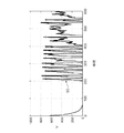
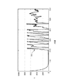
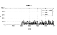
図4は、入力なし(0〜200時間ステップ)、確率興奮性入力(201〜400時間ステップ)、および確率興奮性抑制性入力(401〜600時間ステップ)に対するCD−IF w/RP&CB−I電子ニューロンの応答グラフ例53を示している。各時間ステップ内の入力スパイクの数はガウス分布(μ=1,δ=1)から引き出され、負数はゼロに丸められている。使用されるパラメータ値は、s+=26、s-=25、θ=700、Vreset=0、ρ=8、およびτg=8、gscale=8である。図9は、図4と同じ刺激列に対する抑制性コンダクタンスgの値のグラフ例54を示している。
FIG. 4 shows CD-IF w / RP & CB-I electrons for no input (0-200 hour steps), stochastic excitatory input (201-400 hour steps), and stochastic excitatory inhibitory input (401-600 hour steps). The neuron response graph example 53 is shown. The number of input spikes in each time step is derived from a Gaussian distribution (μ = 1, δ = 1), and negative numbers are rounded to zero. The parameter values used are s + = 2 6 , s − = 2 5 , θ = 700, V reset = 0, ρ = 8, and τ g = 8, g scale = 8. FIG. 9 shows an
不応期およびコンダクタンスベースのシナプス付き凸状減衰統合発火型(CD−IF w/RP&CB−S)
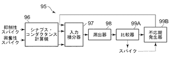
本発明の第4の実装例は、図8のブロック図例によって示されているように、不応期およびコンダクタンスベースのシナプス付き凸状減衰近似統合発火型(CD−IF w/RP&CB−S)電子ニューロン95を含む。シナプス・チャネル・コンダクタンスは指数コンダクタンス変数g1およびg2の差としてモデル化され、これらの変数はニューロンへの各入力によって強度係数sだけ増加する。次に、シナプス・コンダクタンス計算器モジュール96により、コンダクタンス変数は各時間ステップで減衰し、率は時定数τgによって支配される。各時間ステップにおいて、入力積分器モジュール97が以下のようにシナプス電流を使用することにより、ニューロン膜電位Vが変更される。
ここで、gscaleはgの倍率であり、Erevはチャネル逆転電位であって、抑制性チャネルの場合は0になり、興奮性チャネルの場合は210+2EEshiftになるように想定されている。膜漏れは、漏出器モジュール98が各時間ステップ内で時定数τに応じてVを減衰することによってシミュレートされる(したがって、静止膜電位が0であると想定する)。比較器モジュール99Aにより、ニューロン95への入力がしきい値θより上にVを増加する場合、ニューロンはスパイクを生成し、VがVresetに設定される。不応期発生器99Bにより、ニューロンがスパイクを生成すると、ρ時間ステップの間、VをVresetに保持することによって不応期がシミュレートされる。
Refractory period and conductance-based synaptic convex decay integrated firing type (CD-IF w / RP & CB-S)
A fourth implementation of the present invention is a refractory period and conductance-based, synaptic, convexly damped approximate integrated firing (CD-IF w / RP & CB-S) electrons, as illustrated by the block diagram example of FIG.
Here, g scale is the magnification of g, and E rev is the channel reversal potential, which is assumed to be 0 for the inhibitory channel and 2 10 +2 EEshift for the excitatory channel. . Membrane leakage is simulated by the
すべてのパラメータは非負整数であり、n+は受信した興奮性スパイクの数であり(整数[0,63])、n-は受信した抑制性スパイクの数であり(整数[0,63])、s+は∈{0,1,2,4,8,16,32,64,128}である興奮強度であり、s-は∈{0,1,2,4,8,16,32,64,128}である抑制強度であり、効率のために、s+およびs-は2の累乗になるように制限されており、θはスパイクしきい値(Vと同じ分解能を有する整数)であり、Vresetはリセット電圧であって、θより小さい任意の正整数にすることができ、τは∈{1,2,4,8...210}である膜時定数であり、効率のために、τはVの範囲内の2の累乗になるように制限されており、τgI1は∈{1,2,4,8...28}である第1の抑制性コンダクタンス時定数であり、τgI2は∈{1,2,4,8...28}である第2の抑制性コンダクタンス時定数であり、τgE1は∈{1,2,4,8...28}である第1の興奮性コンダクタンス時定数であり、τgE2は∈{1,2,4,8...28}である第2の興奮性コンダクタンス時定数であり、効率のために、すべてのτgはgの範囲内の2の累乗になるように制限されており、ρは不応期であり(整数[0,63])、gEscaleは興奮性コンダクタンスに関する区分倍率であり(整数[10,16])、gIscaleは抑制性コンダクタンスに関する区分倍率であり(整数[10,16])、EEShiftはしきい値より大きい興奮性逆転電位に合わせて調整する(整数[10,13])。本明細書に示されているパラメータ範囲は例に過ぎない。当業者であれば、本発明の諸実施形態では複数のパラメータ範囲が可能であり有用であることを認識するであろう。 All parameters are non-negative integers, n + is the number of excitatory spikes received (integer [0, 63]), and n − is the number of inhibitory spikes received (integer [0, 63]). , S + is the excitation intensity with ∈ {0, 1, 2, 4, 8, 16, 32, 64, 128}, and s − is ∈ {0, 1, 2, 4, 8, 16, 32, 64,128}, and for efficiency, s + and s − are limited to powers of 2, and θ is the spike threshold (an integer with the same resolution as V). V reset is the reset voltage and can be any positive integer smaller than θ, and τ is ∈ {1, 2, 4, 8,. . . 2 10 }, for efficiency, τ is limited to be a power of 2 in the range of V, and τ gI1 is ∈ {1, 2, 4, 8 ,. . . 2 8 } is the first inhibitory conductance time constant, and τ gI2 is ∈ {1, 2, 4, 8 ,. . . 2 8 }, the second inhibitory conductance time constant, τ gE1 is ∈ {1, 2, 4, 8 ,. . . 2 8 } is the first excitatory conductance time constant, and τ gE2 is ∈ {1, 2, 4, 8 ,. . . 2 8 } is the second excitatory conductance time constant, and for efficiency, all τ g are limited to powers of 2 within g, and ρ is the refractory period ( Integer [0, 63]), g Escale is the fractional magnification for excitatory conductance (integer [10, 16]), g Iscale is the fractional magnification for inhibitory conductance (integer [10, 16]), E EShift Is adjusted to an excitatory reversal potential greater than the threshold (integer [10, 13]). The parameter ranges shown herein are only examples. One skilled in the art will recognize that multiple parameter ranges are possible and useful in embodiments of the present invention.
ダイナミクスに関しては、Vは膜電圧(10ビットで表される非負整数)であり、Vは折り返さず、Vがすでにゼロである場合にV−1は依然としてゼロになる。rは不応期カウンタ(6ビットで表される正整数)であり、rは折り返さない。gI1は抑制性指数変数1(10ビットで表される正整数)である。gI2は抑制性指数変数2(10ビットで表される正整数)である。gE1は興奮性指数変数1(10ビットで表される正整数)である。gE2は興奮性指数変数2(10ビットで表される正整数)である。すべてのg値は折り返さない。 With respect to dynamics, V is the membrane voltage (a non-negative integer expressed in 10 bits), V does not wrap around, and V-1 is still zero when V is already zero. r is a refractory period counter (a positive integer represented by 6 bits), and r does not wrap around. g I1 is an inhibitory index variable 1 (a positive integer represented by 10 bits). g I2 is an inhibitory exponent variable 2 (a positive integer represented by 10 bits). g E1 is the excitability index variable 1 (a positive integer represented by 10 bits). g E2 is the excitability index variable 2 (a positive integer represented by 10 bits). All g values do not wrap.
このニューロンに関する更新規則は、以下のものを含む。
に応じてgI1を更新する。
に応じてgI2を更新する。
に応じてgE1を更新する。
に応じてgE2を更新する。
ここで、τgは2の累乗であり、−g(t−1)/τgはg(t−1)のビットシフト減算であり、s-は2の累乗であり、−s-n-はn-のビットシフト減算であり、s+は2の累乗であり、+s+n+はn+のビットシフト加算である。
The update rules for this neuron include:
G I1 is updated accordingly.
G I2 is updated accordingly.
Update g E1 accordingly.
G E2 is updated accordingly.
Where τ g is a power of 2, −g (t−1) / τ g is a bit shift subtraction of g (t−1), s − is a power of 2, and −s − n −. Is a bit shift subtraction of n − , s + is a power of 2, and + s + n + is a bit shift addition of n + .
r(t)>0である場合、r(t)=r(t−1)−1であり、Vを更新せず、
さもなければ、
に応じてVを更新する。
ここで、kI=gIscale−floor(log2(gI1−gI2))であり、kE=gEscale−floor(log2(gE1−gE2))であり、kは整数であり、x/2kはxのビットシフト・バージョンであり、floor(log2(x))はx内の最上位非ゼロ・ビットの位置であり、210−VはVのビット単位の補数であり、210−V+EEShiftは210−Vのビットシフト・バージョンである。さらに、τは−V(t−1)/τがV(t−1)のビットシフト減算になるような2の累乗である。
If r (t)> 0, then r (t) = r (t−1) −1, V is not updated,
Otherwise,
V is updated accordingly.
Here, k I = g Iscale −floor (log 2 (g I1 −g I2 )), k E = g Escale −floor (log 2 (g E1 −g E2 )), and k is an integer. , X / 2 k is a bit-shifted version of x, floor (log 2 (x)) is the position of the most significant non-zero bit in x, and 2 10 −V is the bitwise complement of V Yes , 2 10 −V + E EShift is a 2 10 −V bit-shifted version. Furthermore, τ is a power of 2 such that −V (t−1) / τ is a bit shift subtraction of V (t−1).
このニューロンに関するスパイク条件は以下のものを含む。
V(t)>θである場合、r(t)=ρを設定し、スパイクを放出する。
The spike conditions for this neuron include:
If V (t) > θ, set r (t) = ρ and emit a spike.
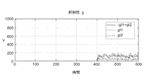
図10は、入力なし(0〜200時間ステップ)、確率興奮性入力(201〜400時間ステップ)、および確率興奮性抑制性入力(401〜600時間ステップ)に対するCD−IF w/RP&CB−S電子ニューロンの応答グラフ例55を示している。各時間ステップ内の入力スパイクの数はガウス分布(μ=1,δ=1)から引き出され、負数はゼロに丸められている。使用されるパラメータ値は、s+=26、s-=25、θ=700、Vreset=0、ρ=8、τ=16、τgI1=2、τgI2=8、τgE1=1、τgE2=2,gIscale=10、gEscale=12、EEShift=12、gscale=8である。 FIG. 10 shows CD-IF w / RP & CB-S electrons for no input (0-200 hour steps), stochastic excitatory input (201-400 hour steps), and stochastic excitatory inhibitory input (401-600 hour steps). The neuron response graph example 55 is shown. The number of input spikes in each time step is derived from a Gaussian distribution (μ = 1, δ = 1), and negative numbers are rounded to zero. The parameter values used are s + = 2 6 , s − = 2 5 , θ = 700, V reset = 0, ρ = 8, τ = 16, τ gI1 = 2, τ gI2 = 8, τ gE1 = 1. Τ gE2 = 2; g Iscale = 10; g Escale = 12; E EShift = 12; g scale = 8.
図11は、図10と同じ刺激列に対する抑制性コンダクタンスgの値のグラフ例を示している。図12は、図10と同じ刺激列に対する興奮性gの値のグラフ例を示している。 FIG. 11 shows a graph example of the value of the inhibitory conductance g with respect to the same stimulus row as FIG. FIG. 12 shows a graph example of the value of excitability g for the same stimulus sequence as FIG.
本明細書に記載されている本発明の実装例では、興奮強度パラメータおよび抑制強度パラメータs+およびs-は2の累乗に制限されている。この制限により、電子ニューロンは、単純なビットシフト操作を使用して、各時間ステップ内に受信した興奮性スパイクおよび抑制性スパイクの数n+およびn-にそれぞれの強度パラメータを掛けることによって、入力スパイクを効率よく統合することができる。次に、加算または減算により、結果値を電圧またはシナプス・コンダクタンスのうち電子ニューロンに適した方に統合することができる。 In the implementation of the invention described herein, the excitation intensity parameter and the suppression intensity parameter s + and s − are limited to a power of two. Due to this limitation, the electronic neuron uses a simple bit-shift operation to multiply the number of excitatory and inhibitory spikes received within each time step, n + and n − by the respective intensity parameter. Spikes can be efficiently integrated. The result value can then be integrated into the voltage or synaptic conductance that is appropriate for the electronic neuron by addition or subtraction.
シナプス強度パラメータを2の累乗に制限することによって提供されるものより精密な制御がそれらのパラメータに対して行われることが望ましい場合がある。このような制御は、シナプス強度パラメータを所与の範囲内の任意の正整数(たとえば、[0,127])にして、さらに柔軟性を提供することによって達成することができる。次に、n+回だけ適切な変数にs+を加えることによって興奮性スパイクを統合することができ、n-回だけ適切な変数からs-を引くことによって抑制性スパイクを統合することができる。電子ニューロンが時間ステップあたり多くても1つの興奮性入力スパイクと1つの抑制性入力スパイクを受信する場合、この実装例は上記で詳述した実装例と同じ程度に効率が良いものである。 It may be desirable to have more precise control over those parameters than provided by limiting the synaptic strength parameters to a power of two. Such control can be achieved by making the synaptic strength parameter any positive integer within a given range (eg, [0,127]) to provide more flexibility. Next, excitatory spikes can be integrated by adding s + to the appropriate variable n + times, and inhibitory spikes can be integrated by subtracting s − from the appropriate variable n − times. . If an electronic neuron receives at most one excitatory input spike and one inhibitory input spike per time step, this implementation is as efficient as the implementation detailed above.
CD−IFニューロン膜電位更新規則は以下の通りである。
これは、上記の第2および第3の実装例に関するものであり、伝統的な統合発火型(IF)ニューロン・モデルで使用される膜電圧の指数関数的減衰に対する凸状近似を提供し、したがって、以下の対応する膜更新規則に比較してより高度の生物学的リアリズムが得られる。
V(t)=V(t−1)−λ+s+n+−s-n-
これは、本発明の第1の実施形態に関するものであり、時間の経過につれて膜電圧が一定の直線傾斜下降することを使用する。
The CD-IF neuron membrane potential renewal rule is as follows.
This relates to the second and third implementations described above and provides a convex approximation to the exponential decay of membrane voltage used in the traditional integrated firing (IF) neuron model, and thus Higher biological realism is obtained compared to the corresponding membrane renewal rules below.
V (t) = V (t−1) −λ + s + n + −s − n −
This relates to the first embodiment of the present invention, which uses the fact that the membrane voltage falls with a constant linear slope over time.
以下のように混合膜更新規則を使用することもできる。
ここで、電圧依存区分漏れおよび電圧非依存線形漏れの項の両方を使用して、この混合膜更新規則はさらに同調可能性を提供する。
A mixed film renewal rule can also be used as follows.
Here, using both voltage-dependent piecewise leakage and voltage-independent linear leakage terms, this mixed film update rule provides further tunability.
本発明の一実施形態により、混合膜更新規則を実装するニューロン・シナプス型システムが上記の本発明の第1、第2、および第3の実装例の挙動を複製する際のパラメータ値を選択することができる。 According to an embodiment of the present invention, a neuron-synaptic system that implements a mixed film update rule selects parameter values for duplicating the behavior of the first, second, and third implementation examples of the present invention described above. be able to.
イベントベースのニューロン更新も使用することができる。本明細書に記載されている更新規則はデジタル・クロック駆動方式で電子ニューロンの更新を提供し、1つまたは複数の状態変数は各時間ステップで変化する。イベントが発生したときに状態変数のみが変化するように、イベントベースの方式でニューロンをシミュレートすることができる。これは、各ニューロンに関するカウンタKを保持することによって達成することができ、このカウンタはイベントが発生するたびにゼロに設定され、各時間ステップで1だけ増分する。次に、このカウンタにより、イベントが発生するたびに状態変数プロセスが変化する。たとえば、本発明の第1の実装例に関するプロセスは以下のように変化する。
更新規則:
V=V−Kλ+s+n+−s-n-に応じてVを更新する。
s+は2の累乗であるので、+s+n+はn+のビットシフト加算である。
s-は2の累乗であるので、−s-n-はn-のビットシフト減算である。
スパイク条件:
V(t)>θである場合、
V(t)=Vresetを設定し、スパイクを放出する。
Event-based neuron updates can also be used. The update rules described herein provide for electronic neuron updates in a digital clocked manner, with one or more state variables changing at each time step. Neurons can be simulated in an event-based manner so that only state variables change when an event occurs. This can be accomplished by maintaining a counter K for each neuron, which is set to zero each time an event occurs and increments by 1 at each time step. This counter then changes the state variable process each time an event occurs. For example, the process for the first implementation of the present invention changes as follows.
Update rules:
V = V-Kλ + s + n + -s - n - to update the V in accordance with the.
Since s + is a power of 2, + s + n + is a bit shift addition of n + .
Since s − is a power of 2, −s − n − is a bit shift subtraction of n − .
Spike condition:
If V (t) > θ,
Set V (t) = V reset and release spikes.
このため、本発明の諸実施形態は専用デジタル電子ニューロンを使用して生物学的脳のシミュレーションを容易にし、この電子ニューロンは製作中に発生する小規模なハードウェアの変動の影響をあまり受けない。 For this reason, embodiments of the present invention use dedicated digital electronic neurons to facilitate biological brain simulation, which is less sensitive to small hardware variations that occur during fabrication. .
本発明の諸実施形態はさらに、完全に非同期で電力効率が良いニューロン・シナプス型ハードウェア実装により、混合モード・デジタル・アナログ統合発火型電子ニューロンを提供する。 Embodiments of the present invention further provide a mixed mode digital-analog integrated firing electronic neuron with a fully asynchronous and power efficient neuron-synaptic hardware implementation.
図13は、本発明による混合モード・デジタル・アナログ統合発火型電子ニューロン60の実装例の図を示している。混合モード・ニューロンはその膜電位(状態)をデジタル状態カウンタ62で維持する。このニューロンが興奮性ニューロンからのスパイクを含む外部信号を受信すると、状態カウンタ62は小さい整数(典型的に1に設定される)だけ増分される。このニューロンが抑制性ニューロンからのスパイクを含む外部信号を受信すると、状態カウンタ62は小さい整数(典型的に1に設定される)だけ減分される。変更する必要がある状態カウンタ62内のビットのみが変更されるように、この増分および減分は電力効率が良いビット単位の方式で実行される。状態カウンタが比較器63によって決定されたしきい値を超えた場合、このニューロンは発火し、パルス・モジュール64を介してスパイクを放出する。
FIG. 13 shows a diagram of an example implementation of a mixed mode digital / analog integrated firing
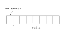
図14では、状態カウンタ62のMSB(最上位ビット)および下位ビット(MSBビット以外のものすべて)が識別されている。減衰イベントを発生するためのメカニズム61が設けられている(図13)。減衰イベントが発生したときに以下のものを実装することによって効率の良い状態カウンタ漏れを達成することができる。
状態カウンタのMSBが1である場合、
状態カウンタのMSBがゼロに設定される。
さもなければ
すべての下位ビットがゼロに設定される。
終了。
In FIG. 14, the MSB (most significant bit) and the lower bits (all except the MSB bit) of the
If the MSB of the status counter is 1,
The MSB of the status counter is set to zero.
Otherwise, all lower bits are set to zero.
End.
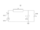
図15を参照すると、第1の実施形態では、減衰イベントを発生するためのメカニズム61は、数ミリ秒のRC時定数を有するアナログ抵抗−容量(RC)回路を含む(たとえば、約5〜20msecの範囲内の値により、電子ニューロンは生物ニューロンで観察された挙動を再生することができるであろう)。電子ニューロン60がスパイクを生成すると、容量Cは急速に放電される。
Referring to FIG. 15, in a first embodiment, a
次に、容量Cは、図16の例によって示されているように、ゆっくり充電する。容量Cがしきい値(たとえば、その完全充電の86.5%)に到達すると、減衰イベントが発生し、以下の動作が回路61内で実行される。
容量61Aはスイッチ61Bを介して急速に放電され、電流源61Dからスイッチ61Cを介してもう一度充電を開始する。
状態カウンタ62のMSBが1である場合、
状態カウンタのMSBがゼロに設定される。
さもなければ
すべての下位ビットがゼロに設定される。
終了。
Next, the capacitor C is slowly charged as shown by the example of FIG. When capacity C reaches a threshold value (eg, 86.5% of its full charge), a decay event occurs and the following operations are performed in
The
When the MSB of the
The MSB of the status counter is set to zero.
Otherwise, all lower bits are set to zero.
End.
第2の実施形態では、減衰イベントを発生するためのメカニズム61は、数ミリ秒のRC時定数を有するRC回路(図15の例によって示されているものなど)を含む(たとえば、約5〜20msecの範囲内の値により、電子ニューロンは生物ニューロンで観察された挙動を再生することができるであろう)。電子ニューロン60がスパイクを生成すると、容量Cは急速に放電される。さらに、以下の動作が実行される。
ステップ1:容量Cは開始値からゆっくり充電する(図16)。スパイク・イベントが発生したばかりである場合、開始値はゼロであり、そうではない場合、開始値は、容量Cがすでに備えている電荷である。容量Cが第1のしきい値(たとえば、その完全充電の86.5%)に到達すると、減衰イベントが発生し、以下の動作が実行される。
状態カウンタ62(図13)のMSBが1である場合、
状態カウンタ62のMSBがゼロに設定される。
さもなければ
状態カウンタ62のすべての下位ビットがゼロに設定される。
終了。
ステップ2に移行する。
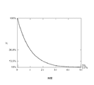
ステップ2:次に容量Cは、それがすでに備えている電荷から始めて、図17に示されているようにゆっくり放電する。容量Cが第2のしきい値(たとえば、その完全充電の約13.5%または14.5%)に到達すると、減衰イベントが発生し、以下の動作が実行される。
状態カウンタ62(図13)のMSBが1である場合、
状態カウンタ62のMSBがゼロに設定される。
さもなければ
状態カウンタ62のすべての下位ビットがゼロに設定される。
終了。
ステップ1に移行する。ステップ1の充電はこの時点では空の容量からではなく、容量がすでに備えている電荷から始めることになる。
In a second embodiment, the
Step 1: The capacity C is slowly charged from the start value (FIG. 16). If the spike event has just occurred, the starting value is zero, otherwise the starting value is the charge that the capacitor C already has. When capacity C reaches a first threshold (eg, 86.5% of its full charge), a decay event occurs and the following operations are performed.
When the MSB of the status counter 62 (FIG. 13) is 1,
The MSB of the
Otherwise, all the low order bits of the
End.
Move to step 2.
Step 2: The capacitor C then discharges slowly as shown in FIG. 17, starting with the charge it already has. When capacity C reaches a second threshold (eg, about 13.5% or 14.5% of its full charge), a decay event occurs and the following operations are performed.
When the MSB of the status counter 62 (FIG. 13) is 1,
The MSB of the
Otherwise, all the low order bits of the
End.
Move to step 1. The charging in
パーセンテージに関しては、好ましくは以下のようになる。
第1のしきい値+第2のしきい値=100%
With respect to the percentage, preferably:
First threshold + second threshold = 100%
上記のステップ1とステップ2は互いに逆であり、ステップ1ではエネルギー(すなわち、電荷)が容量Cに供給され、ステップ2ではエネルギーが容量Cから抽出される。このため、正味のエネルギー損失は削減される。
状態カウンタ62は、電子ニューロン60が興奮性信号を受信したときに増分動作を続行し、電子ニューロン60が抑制性信号を受信したときに減分動作を続行する。いつでも状態カウンタ62がしきい値(たとえば、約255)に到達した場合、電子ニューロン60は発火し、スパイク信号を放出する。電子ニューロン90がスパイクを生成すると、容量Cは急速に放電される。
The
上記の例では、スパイク・イベントが発生すると、容量Cが放電される。エネルギー損失を回避するために、放電動作を除去することができる。これは、追加の異質性と、ニューロン発火におけるランダム性の発生源をもたらすものである。 In the above example, when a spike event occurs, the capacitor C is discharged. In order to avoid energy loss, the discharge operation can be eliminated. This provides additional heterogeneity and a source of randomness in neuronal firing.
代わって、抵抗とインダクタと容量とを含むRLC回路において、2つの容量を使用することができる。ニューロンは、両方の容量が放電状態にある状態から始める。最初は、第1の容量が電流源を介してしきい値に到達するまで第1の容量が充電され、その間に第2の容量はインダクタを介して電流源に放電する。第1の容量がしきい値に到達すると、2つの容量の役割が逆転する。次に、第2の容量が電流源を介してしきい値に到達するまで第2の容量が充電され、その間に第1の容量はインダクタを介して電流源に放電する。第2の容量がしきい値に到達すると、2つの容量の役割がもう一度逆転する。このように、サイクルが継続する。したがって、2つの容量を交互にすることにより、エネルギー損失が最小限になる。 Alternatively, two capacitors can be used in an RLC circuit that includes a resistor, an inductor, and a capacitor. A neuron begins with both capacitances in a discharged state. Initially, the first capacitor is charged until the first capacitor reaches a threshold value via the current source, during which time the second capacitor is discharged to the current source via the inductor. When the first capacity reaches the threshold, the roles of the two capacities are reversed. Next, the second capacitor is charged until the second capacitor reaches a threshold value via the current source, during which the first capacitor is discharged to the current source via the inductor. When the second capacity reaches the threshold, the roles of the two capacities are reversed again. In this way, the cycle continues. Thus, alternating the two capacities minimizes energy loss.
本発明による混合モード電子ニューロンの諸実施形態は、いくつかのこのようなニューロン間の非同期動作を提供し、減衰容量に関するエネルギー消費を削減する際に効率的である(容量内のエネルギー損失は、スパイク・イベントが発生したときにのみ発生し、必要であれば、これさえも最小限にすることができる)。混合モード・ニューロンは、状態カウンタを操作する際に最小限のエネルギーを必要とする(状態カウンタに関するエネルギー損失は、新しい情報が到着したとき、または減衰イベントが発生したとき、またはスパイク・イベントが発生したときにのみ発生する)。ニューロン間には固有の異質性が存在する。ニューロンは、自然にバイナリ・シナプスとのインターフェースを取り、ニューロン同士を相互接続するためにクロスバー・アレイとの高速インターフェース(たとえば、10nsec未満)をサポートする(アナログ専用ニューロンは長時間(0.1ms)の電流の流れを必要とする)。混合モード・ニューロンは、蓄積(デジタル状態カウンタ)および減衰(アナログRC回路)のプロセスを分離する。 Embodiments of mixed-mode electronic neurons according to the present invention provide some asynchronous operation between such neurons and are efficient in reducing energy consumption with respect to attenuation capacity (energy loss in capacity is It only occurs when a spike event occurs, and even this can be minimized if necessary). Mixed-mode neurons require minimal energy when operating the state counter (energy loss for the state counter occurs when new information arrives, when a decay event occurs, or when a spike event occurs Only occurs when There is inherent heterogeneity between neurons. Neurons naturally interface with binary synapses and support high-speed interfaces with crossbar arrays (eg, less than 10 nsec) to interconnect neurons (analog-only neurons are long (0.1 ms) ) Need current flow)). A mixed mode neuron separates the process of accumulation (digital state counter) and decay (analog RC circuit).
低電力イベント・ドリブン(LPED)電子ニューロン回路は、上記のLL−IFニューロンをハードウェアで実現したものである。LPED電子ニューロンは、貴重な資源(たとえば、クロスバー・アレイへのアクセス)を解放するために迅速にイベントを処理する。イベントは比較的低速で到着するので(たとえば、各ニューロンは平均して10,000入力×10Hz=105イベント/秒で受信する)、本発明の一実施形態による純粋なイベント・ドリブン電子ニューロンは、低い動的電力消費により改善されたサービス時間(たとえば、イベントあたり数ナノ秒未満)を提供する。 A low power event-driven (LPED) electronic neuron circuit is a hardware implementation of the LL-IF neuron described above. LPED electronic neurons process events quickly to free valuable resources (eg, access to a crossbar array). Since events arrive relatively slowly (eg, each neuron receives on average 10,000 inputs × 10 Hz = 10 5 events / second), a pure event-driven electronic neuron according to one embodiment of the present invention is Provide improved service time (eg, less than a few nanoseconds per event) with low dynamic power consumption.
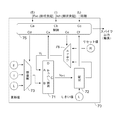
図18は、クロスバー・アレイ回路12に接続された本発明の一実施形態によるLPED電子ニューロン70の図を示している。図19は、本発明の一実施形態による、図18のLL−IF LPED電子ニューロン70に関する回路のより詳細な図を示している。ニューロン・パラメータ(たとえば、8ビットの符号付きの値)としては、興奮性シナプス強度(E)、抑制性シナプス強度(I)、漏れ強度(L)、リセット値(R)、およびしきい値(T)を含む。
FIG. 18 shows a diagram of an LPED
この実施形態では、LPED電子ニューロン70は2つの樹状突起チャネル(ExcおよびInh)上でシナプス・イベントを受信し、これらのイベントは、クロスバー・アレイ、仮想化ネットワークを含む多数の発生源から到着するか、または他のニューロンから発生した軸索から直接、到着する可能性がある。イベントは相互排他的に(一度に1つずつ)到着し、各イベントは他のイベントを受け入れる前にLPED電子ニューロン70によって完全に処理される。他の実施形態では、イベント到着は排他的になるように制限されないが、LPED電子ニューロン70は、一度に1つずつ選択して、その複数入力間でアービトレーションを行う必要がある。また、LPED電子ニューロン70は、個別チャネル上で同期イベントも受信する。その出力のために、LPED電子ニューロン70は軸索チャネル上でスパイク・イベントを送信する。
In this embodiment, LPED
イベント・ドリブン・ニューロン・システムでは、イベントが到着する順序はアービトレーションのために決定的ではない。非決定的イベント到着が存在する場合でも、1)すべての保留シナプス・イベントが時間ウィンドウt内で処理される(ニューロン膜電位Vtが一度にイベント1つずつについて更新される)シナプス更新フェーズと、2)スパイク・イベントが存在するかどうかを判断するためにVtとしきい値が比較されるスパイク計算フェーズという2つのフェーズに計算を分けることにより、LPEDニューロンをソフトウェア記述に正確に一致させることができる。スパイクの有無をチェックする前に、第1のフェーズでイベントが処理される順序がVtの最終値を変更しないので(ニューロンが線形であるため)、LPEDニューロンは決定的な挙動を示す。 In an event-driven neuron system, the order in which events arrive is not definitive due to arbitration. Even if there is a non-deterministic event arrival: 1) all pending synaptic events are processed in time window t (the neuron membrane potential V t is updated for one event at a time); by dividing the calculated two phases spike calculation phase V t and the threshold are compared to 2) a spike event to determine whether there, it is made to coincide accurately LPED neurons software description it can. Before checking for spikes, LPED neurons behave deterministically because the order in which events are processed in the first phase does not change the final value of V t (because the neurons are linear).
ニューロン70は、制御モジュール75と、更新値モジュール73と、リセット・モジュール76と、加算器/ラッチ・モジュール71と、比較モジュール72とを含む。制御モジュール75は、シナプス・イベント用のCaおよびCbと、同期イベント用のCcと、Vtの符号(正または負)を決定するためのCxと、Vt>T(しきい値)という条件を判断するためのCfという5つの入力チャネルを有する。ニューロン70は、Vtを更新するための値を選択するためのCdと、VtをリセットするためのCeと、スパイク・イベントを送信するためのCsという3つの出力チャネルを有する。更新値モジュール73は、Vtに対して可能な更新の値を保管し、選択するための3つの値(8ビットの符号付きの数値)、すなわち、E、I、およびLを有する。この値は、Cdによって制御モジュール75から選択され、加算器/ラッチ・モジュール71に送信される。加算器/ラッチ・モジュール71は、Aと値BとしてVtについて11ビットの符号付き加算を実行し、C上に合計Vt+1を生成し、D上で加算の符号を送信する。この合計は加算器71の出力にあるラッチに保管される。リセット・モジュール76は、Vtをリセット値Rで置き換えるか、または制御モジュール75からのCe上で不変かつ条件付きのVt+1を送信する。比較モジュール72は、Vt+1をTと比較し、その結果をCf上で制御モジュール75に送信する。
The
本明細書で使用する電子ニューロンという用語は、生物ニューロンをシミュレートするように構成されたアーキテクチャを表す。電子ニューロンは、生物学的脳のニューロンと機能的にほぼ同等の処理要素間の接続を作成する。このため、本発明の諸実施形態による電子ニューロンを含むニューロン・シナプス型システムは、生物ニューロンを手本にした様々な電子回路を含むことができる。さらに、本発明の諸実施形態による電子ニューロンを含むニューロン・シナプス型システムは、生物ニューロンを手本にした様々な処理要素(コンピュータ・シミュレーションを含む)を含むことができる。電子回路を含む電子ニューロンを使用して本発明の特定の例示的な諸実施形態について本明細書で説明してきたが、本発明は電子回路に限定されない。本発明の諸実施形態によるニューロン・シナプス型システムは、回路を含むニューロン・シナプス型アーキテクチャとして、さらにコンピュータ・シミュレーションとして実装することができる。実際に、本発明の諸実施形態は、完全にハードウェアの実施形態、完全にソフトウェアの実施形態、またはソフトウェア要素とハードウェア要素の両方を含む一実施形態の形を取ることができる。 As used herein, the term electronic neuron represents an architecture configured to simulate biological neurons. Electronic neurons create connections between processing elements that are approximately functionally equivalent to neurons in the biological brain. Thus, neuron-synaptic systems including electronic neurons according to embodiments of the present invention can include various electronic circuits modeled on biological neurons. Furthermore, neuron-synaptic systems including electronic neurons according to embodiments of the present invention can include various processing elements (including computer simulations) modeled on biological neurons. Although specific exemplary embodiments of the present invention have been described herein using electronic neurons including electronic circuits, the present invention is not limited to electronic circuits. The neuron synapse type system according to the embodiments of the present invention can be implemented as a neuron synapse type architecture including a circuit and further as a computer simulation. Indeed, embodiments of the invention may take the form of an entirely hardware embodiment, an entirely software embodiment or an embodiment containing both software and hardware elements.
本発明の諸実施形態は、コンピュータ、処理装置、または任意の命令実行システムによりあるいはそれに関連して使用するためのプログラム・コードを提供するコンピュータ使用可能媒体またはコンピュータ可読媒体からアクセス可能なコンピュータ・シミュレーションまたはプログラムの形を取ることができる。当業者であれば認識するように、本発明の諸態様は、システム、方法、またはコンピュータ・プログラムとして実施することができる。したがって、本発明の諸態様は、完全にハードウェアの実施形態、完全にソフトウェアの実施形態(ファームウェア、常駐ソフトウェア、マイクロコードなどを含む)、またはソフトウェア態様とハードウェア態様を結合した一実施形態の形を取ることができ、このような実施形態は一般に本明細書ではいずれも「回路」、「モジュール」、または「システム」と呼ぶことができる。さらに、本発明の諸態様は、コンピュータ可読プログラム・コードがそこに実施されている1つまたは複数のコンピュータ可読媒体に実施されたコンピュータ・プログラムの形を取ることもできる。 Embodiments of the present invention are computer simulations accessible from a computer-usable or computer-readable medium that provide program code for use by or in connection with a computer, processing device, or any instruction execution system. Or it can take the form of a program. As will be appreciated by one skilled in the art, aspects of the present invention may be implemented as a system, method, or computer program. Accordingly, aspects of the present invention can be implemented in a fully hardware embodiment, a fully software embodiment (including firmware, resident software, microcode, etc.), or an embodiment that combines a software aspect and a hardware aspect. Any such embodiment may generally be referred to herein as a “circuit”, “module”, or “system”. Further, aspects of the invention may take the form of a computer program implemented on one or more computer readable media having computer readable program code embodied thereon.
1つまたは複数のコンピュータ可読媒体の任意の組み合わせを使用することができる。コンピュータ可読媒体は、コンピュータ可読信号媒体またはコンピュータ可読記憶媒体にすることができる。コンピュータ可読記憶媒体は、たとえば、電子、磁気、光、電磁、赤外線、または半導体システム、装置、あるいはデバイス、もしくはこれらの任意の適切な組み合わせにすることができるが、これらに限定されないものである。コンピュータ可読記憶媒体のより具体的な例(非網羅的リスト)としては、1つまたは複数のワイヤを有する電気接続、ポータブル・コンピュータ・ディスケット、ハード・ディスク、ランダム・アクセス・メモリ(RAM)、読み取り専用メモリ(ROM)、消去可能プログラム可能読み取り専用メモリ(EPROMまたはフラッシュ・メモリ)、光ファイバ、ポータブル・コンパクト・ディスク読み取り専用メモリ(CD−ROM)、光記憶装置、磁気記憶装置、またはこれらの任意の適切な組み合わせを含むであろう。本書に関連して、コンピュータ可読記憶媒体は、命令実行システム、装置、またはデバイスによりあるいはそれに関連して使用するためのプログラムを収容または保管可能な任意の有形媒体にすることができる。 Any combination of one or more computer readable media may be used. The computer readable medium may be a computer readable signal medium or a computer readable storage medium. The computer readable storage medium can be, for example but not limited to, an electronic, magnetic, optical, electromagnetic, infrared, or semiconductor system, apparatus, or device, or any suitable combination thereof. More specific examples (non-exhaustive list) of computer readable storage media include electrical connections with one or more wires, portable computer diskettes, hard disks, random access memory (RAM), reading Dedicated memory (ROM), erasable programmable read only memory (EPROM or flash memory), optical fiber, portable compact disk read only memory (CD-ROM), optical storage, magnetic storage, or any of these Would include an appropriate combination of In connection with this document, a computer-readable storage medium may be any tangible medium that can contain or store a program for use by or in connection with an instruction execution system, apparatus, or device.
コンピュータ可読信号媒体は、たとえば、ベースバンド内にまたは搬送波の一部として、コンピュータ可読プログラム・コードがそこに実施されている伝搬データ信号を含むことができる。このような伝搬信号は、電磁、光、またはこれらの任意の適切な組み合わせを含むがこれらに限定されない様々な形のいずれかを取ることができる。コンピュータ可読信号媒体は、コンピュータ可読記憶媒体ではなく、命令実行システム、装置、またはデバイスによりあるいはそれに関連して使用するためのプログラムを伝達、伝搬、または移送可能な任意のコンピュータ可読媒体にすることができる。 A computer readable signal medium may include a propagated data signal with computer readable program code embodied therein, for example, in baseband or as part of a carrier wave. Such propagated signals can take any of a variety of forms including, but not limited to, electromagnetic, light, or any suitable combination thereof. The computer readable signal medium is not a computer readable storage medium but may be any computer readable medium capable of transmitting, propagating, or transporting a program for use by or in connection with an instruction execution system, apparatus, or device. it can.
コンピュータ可読媒体上に実施されたプログラム・コードは、無線、有線、光ファイバ・ケーブル、RFなど、またはこれらの任意の適切な組み合わせを含むがこれらに限定されない任意の適切な媒体を使用して伝送することができる。本発明の諸態様に関する動作を実行するためのコンピュータ・プログラム・コードは、Java(R)、Smalltalk(R)、C++などのオブジェクト指向プログラミング言語ならびに「C」プログラミング言語または同様のプログラミング言語などの従来の手続き型プログラミング言語を含む、1つまたは複数のプログラミング言語の任意の組み合わせで作成することができる。このプログラム・コードは、スタンドアロン・ソフトウェア・パッケージとして、完全にユーザのコンピュータ上で、一部分はユーザのコンピュータ上で、一部分はユーザのコンピュータ上でしかも一部分はリモート・コンピュータ上で、あるいは完全にリモート・コンピュータまたはサーバ上で実行することができる。後者のシナリオでは、リモート・コンピュータは、ローカル・エリア・ネットワーク(LAN)または広域ネットワーク(WAN)を含む任意のタイプのネットワークを介してユーザのコンピュータに接続される場合もあれば、(たとえば、インターネット・サービス・プロバイダを使用してインターネットを介して)外部コンピュータに対して接続が行われる場合もある。 Program code embodied on a computer readable medium may be transmitted using any suitable medium including, but not limited to, wireless, wired, fiber optic cable, RF, etc., or any suitable combination thereof. can do. Computer program code for performing operations in accordance with aspects of the present invention is conventional, such as object oriented programming languages such as Java®, Smalltalk®, C ++, and “C” programming language or similar programming languages. Can be created in any combination of one or more programming languages, including: This program code is a stand-alone software package that is entirely on the user's computer, partly on the user's computer, partly on the user's computer and partly on the remote computer, or completely remote. It can run on a computer or server. In the latter scenario, the remote computer may be connected to the user's computer via any type of network, including a local area network (LAN) or a wide area network (WAN) (eg, Internet In some cases, a connection is made to an external computer (via the Internet using a service provider).
本発明の諸実施形態による方法、装置(システム)、およびコンピュータ・プログラムの流れ図あるいはブロック図またはその両方に関連して、本発明の諸態様について以下に説明する。流れ図あるいはブロック図またはその両方の各ブロックならびに流れ図あるいはブロック図またはその両方の複数ブロックの組み合わせは、コンピュータ・プログラム命令によって実装可能であることが理解されるであろう。これらのコンピュータ・プログラム命令は、マシンを生産するために汎用コンピュータ、特殊目的コンピュータ、またはその他のプログラマブル・データ処理装置のプロセッサに提供することができ、それにより、コンピュータまたはその他のプログラマブル・データ処理装置のプロセッサを介して実行される命令は流れ図あるいはブロック図またはその両方の1つまたは複数のブロックに指定された機能/動作を実装するための手段を作成することになる。 Aspects of the present invention are described below with reference to flowchart illustrations and / or block diagrams of methods, apparatus (systems) and computer program products according to embodiments of the invention. It will be understood that each block of the flowchart illustrations and / or block diagrams, and combinations of blocks in the flowchart illustrations and / or block diagrams, can be implemented by computer program instructions. These computer program instructions can be provided to a processor of a general purpose computer, special purpose computer, or other programmable data processing device to produce a machine, thereby allowing the computer or other programmable data processing device to The instructions that are executed through the processor will create a means for implementing the specified function / operation in one or more blocks of the flow diagram and / or block diagram.
また、これらのコンピュータ・プログラム命令は、コンピュータ、その他のプログラマブル・データ処理装置、またはその他のデバイスに対して特定の方法で機能するよう指示することができるコンピュータ可読媒体に保管することもでき、それにより、コンピュータ可読媒体に保管された命令は流れ図あるいはブロック図またはその両方の1つまたは複数のブロックに指定された機能/動作を実装する命令を含む生産物(article of manufacture)を生産することになる。 These computer program instructions can also be stored on a computer readable medium that can direct a computer, other programmable data processing apparatus, or other device to function in a particular manner. The instructions stored on the computer readable medium thereby produce an article of manufacture that includes instructions that implement the specified function / operation in one or more blocks of the flowchart and / or block diagram. Become.
また、これらのコンピュータ・プログラム命令は、コンピュータ、その他のプログラマブル・データ処理装置、またはその他のデバイス上にロードして、コンピュータによって実装されるプロセスを生成するためにコンピュータ、その他のプログラマブル装置、またはその他のデバイス上で一連の動作ステップを実行させることができ、それにより、コンピュータまたはその他のプログラマブル装置上で実行される命令は流れ図あるいはブロック図またはその両方の1つまたは複数のブロックに指定された機能/動作を実装するためのプロセスを提供することになる。 These computer program instructions may also be loaded onto a computer, other programmable data processing device, or other device to generate a computer-implemented process, a computer, other programmable device, or other A sequence of operational steps can be performed on a device, such that instructions executed on a computer or other programmable device are functions specified in one or more blocks of a flow diagram and / or block diagram Will provide a process for implementing the operation.
図20は、本発明の一実施形態を実装するために有用な情報処理システムを示す高レベル・ブロック図である。このコンピュータ・システムは、プロセッサ102などの1つまたは複数のプロセッサを含む。プロセッサ102は、通信インフラストラクチャ104(たとえば、通信バス、クロスバー、またはネットワーク)に接続されている。
FIG. 20 is a high-level block diagram illustrating an information processing system useful for implementing an embodiment of the present invention. The computer system includes one or more processors, such as
コンピュータ・システムは、ディスプレイ装置108上に表示するために通信インフラストラクチャ104から(または図示していないフレーム・バッファから)グラフィックス、テキスト、およびその他のデータを転送するディスプレイ・インターフェース106を含むことができる。また、コンピュータ・システムは、好ましくはランダム・アクセス・メモリ(RAM)であるメイン・メモリ110も含み、2次メモリ112を含むこともできる。2次メモリ112は、たとえば、ハード・ディスク・ドライブ114あるいは、たとえば、フレキシブル・ディスク・ドライブ、磁気テープ・ドライブ、または光ディスク・ドライブを表す取り外し可能ストレージ・ドライブ116またはその両方を含むことができる。取り外し可能ストレージ・ドライブ116は、当業者にとって周知の方法で、取り外し可能ストレージ・ユニット118からの読み取りあるいは取り外し可能ストレージ・ユニット118への書き込みまたはその両方を行う。取り外し可能ストレージ・ユニット118は、たとえば、フレキシブル・ディスク、コンパクト・ディスク、磁気テープ、または光ディスクなどを表し、取り外し可能ストレージ・ドライブ116によって読み書きされる。認識されるように、取り外し可能ストレージ・ユニット118は、コンピュータ・ソフトウェアあるいはデータまたはその両方がそこに保管されているコンピュータ可読媒体を含む。
The computer system may include a
代替諸実施形態では、2次メモリ112は、コンピュータ・プログラムまたはその他の命令をコンピュータ・システムにロードできるようにするためのその他の同様の手段を含むことができる。このような手段は、たとえば、取り外し可能ストレージ・ユニット120およびインターフェース122を含むことができる。このような手段の例としては、プログラム・パッケージおよびパッケージ・インターフェース(ビデオ・ゲーム・デバイス内に使用されているものなど)、取り外し可能メモリ・チップ(EPROMまたはPROMなど)および関連ソケット、ならびにその他の取り外し可能ストレージ・ユニット120と取り外し可能ストレージ・ユニット120からコンピュータ・システムにソフトウェアおよびデータを転送できるようにするインターフェース122を含むことができる。
In alternative embodiments,
また、コンピュータ・システムは通信インターフェース124を含むこともできる。通信インターフェース124は、コンピュータ・システムと外部装置との間でソフトウェアおよびデータを転送できるようにするものである。通信インターフェース124の例としては、モデム、ネットワーク・インターフェース(イーサネット・カードなど)、通信ポート、またはPCMCIAスロットおよびカードなどを含むことができる。通信インターフェース124を介して転送されるソフトウェアおよびデータは信号の形になっており、この信号は、たとえば、通信インターフェース124によって受信可能な電子信号、電磁信号、光信号、またはその他の信号にすることができる。これらの信号は通信パス(すなわち、チャネル)126を介して通信インターフェース124に提供される。この通信パス126は、信号を運搬するものであり、ワイヤまたはケーブル、光ファイバ、電話回線、携帯電話リンク、無線周波(RF)リンク、あるいはその他の通信チャネル、またはこれらの組み合わせを使用して実装することができる。
The computer system may also include a
本明細書では、「コンピュータ・プログラム媒体」、「コンピュータ使用可能媒体」、および「コンピュータ可読媒体」という用語は、一般に、メイン・メモリ110および2次メモリ112、取り外し可能ストレージ・ドライブ116、ならびにハード・ディスク・ドライブ114に取り付けられたハード・ディスクなどの媒体を指すために使用されている。
As used herein, the terms “computer program medium”, “computer usable medium”, and “computer readable medium” generally refer to
コンピュータ・プログラム(コンピュータ制御ロジックとも呼ばれる)はメイン・メモリ110あるいは2次メモリ112またはその両方に保管される。また、コンピュータ・プログラムは通信インターフェース124を介して受信することもできる。このようなコンピュータ・プログラムが実行されると、コンピュータ・システムは本明細書で論じた本発明の特徴を実行することができる。特に、コンピュータ・プログラムが実行されると、プロセッサ102はコンピュータ・システムの特徴を実行することができる。したがって、このようなコンピュータ・プログラムは、コンピュータ・システムのコントローラを表す。
Computer programs (also called computer control logic) are stored in
上記の図面内の流れ図およびブロック図は、本発明の様々な実施形態によるシステム、方法、およびコンピュータ・プログラムについて可能な実装例のアーキテクチャ、機能、および動作を例示している。この点に関しては、流れ図またはブロック図内の各ブロックは、指定の論理機能(複数も可)を実装するための1つまたは複数の実行可能命令を含む、コードのモジュール、セグメント、または一部分を表すことができる。また、いくつかの代替実装例では、ブロック内に示された機能は図面内に示された順序から外れて行われる可能性があることにも留意されたい。たとえば、連続して示されている2つのブロックは、関係する機能に応じて、実際にはほぼ同時に実行される場合もあれば、ときには逆の順序で実行される場合もある。また、ブロック図あるいは流れ図またはその両方の各ブロックならびにブロック図あるいは流れ図またはその両方の複数ブロックの組み合わせは、指定の機能または動作を実行する特殊目的ハードウェアベースのシステムによって、または特殊目的ハードウェアとコンピュータ命令の組み合わせによって、実装可能であることも留意されるであろう。 The flowcharts and block diagrams in the above figures illustrate the architecture, functionality, and operation of possible implementations for systems, methods and computer programs according to various embodiments of the present invention. In this regard, each block in the flowchart or block diagram represents a module, segment, or portion of code that includes one or more executable instructions for implementing the specified logical function (s). be able to. It should also be noted that in some alternative implementations, the functions shown in the blocks may be performed out of the order shown in the drawings. For example, two blocks shown in succession may actually be executed substantially simultaneously or sometimes in reverse order depending on the function involved. In addition, each block of the block diagram and / or flowchart and the combination of multiple blocks of the block diagram and / or flowchart may be combined with a special purpose hardware-based system that performs a specified function or operation or with special purpose hardware. It will also be noted that it can be implemented by a combination of computer instructions.
80 線形漏れ統合発火型(LL−IF)電子ニューロン
81 入力積分器
82 漏出器
83 比較器
80 linear leakage integrated firing type (LL-IF)
Claims (26)
漏れ率に基づいて前記デジタル膜電位を減衰するステップと、
前記デジタル膜電位がしきい値を超えたことに応じて、スパイク信号を生成するステップと、
を含む、方法。 In response to an external spike signal of the integrated firing electronic neuron, updating a digital membrane potential representing the neuron membrane potential based on the external spike signal;
Attenuating the digital membrane potential based on a leakage rate;
Generating a spike signal in response to the digital membrane potential exceeding a threshold;
Including a method.
外部興奮性スパイク信号の受信に応じて、1の時間ステップで受信した興奮性スパイク信号の数に第1のスケーリング・パラメータを掛けたものに等しい増加分だけ前記膜電位を増加するステップと、
外部抑制性スパイク信号の受信に応じて、1の時間ステップで受信した抑制性スパイク信号の数に第2のスケーリング・パラメータを掛けたものに等しい減少分だけ前記膜電位を減少させるステップと、
を含む、請求項1記載の方法。 Updating the membrane potential comprises:
In response to receiving an external excitatory spike signal, increasing the membrane potential by an increment equal to the number of excitatory spike signals received in one time step multiplied by a first scaling parameter;
In response to receiving an external inhibitory spike signal, decreasing the membrane potential by a decrease equal to the number of inhibitory spike signals received in one time step multiplied by a second scaling parameter;
The method of claim 1 comprising:
前記抑制性チャネル・コンダクタンス値に基づいて前記膜電位を減少させることにより前記膜電位に抑制を適用するステップと、
をさらに含む、請求項7記載の方法。 Attenuating the inhibitory channel conductance value based on a leakage rate equal to a current value of the inhibitory channel conductance value divided by a time constant, the time constant being a multiple of two, Dividing the inhibitory channel conductance value by the time constant value is performed by a bit shift operation; and
Applying inhibition to the membrane potential by decreasing the membrane potential based on the inhibitory channel conductance value;
The method of claim 7, further comprising:
時定数によって支配される減衰率に基づいて前記コンダクタンス変数を減衰するステップであって、前記時定数が2の倍数であり、前記減衰がデジタル・ビットシフト操作によって行われる、ステップと、
をさらに含む、請求項4記載の方法。 Modeling synaptic channel conductance in the electronic neuron as the difference between two inhibitory channel conductance variables that increase by an intensity factor with each external spike signal;
Attenuating the conductance variable based on a decay rate governed by a time constant, wherein the time constant is a multiple of 2 and the decay is performed by a digital bit shift operation;
The method of claim 4, further comprising:
合計を生成するためにビットシフト操作を使用して膜電位補数値を興奮性強度シフト係数に加えることにより前記膜電位に興奮を適用し、倍率から前記興奮性チャネル・コンダクタンス変数の前記差の値内の最上位非ゼロ・ビットを引いたものに等しい冪指数だけ2を累乗したものである除数で前記合計を割るステップと、
をさらに含む、請求項10記載の方法。 Applying a suppression to the membrane potential by subtracting a current value of the membrane potential divided by a divisor value from the membrane potential, wherein the divisor value is calculated from a factor of the difference of the inhibitory channel conductance variable. A power of 2 by a power that is equal to the most significant non-zero bit minus the value of
Apply excitement to the membrane potential by adding a membrane potential complement value to the excitatory intensity shift factor using a bit shift operation to generate a sum, and multiply the magnitude of the difference value of the excitatory channel conductance variable Dividing the sum by a divisor that is a power of two by a power that is equal to the most significant non-zero bit of
The method of claim 10, further comprising:
外部スパイク信号に基づいて前記膜電位を更新するために構成されたコントローラであって、
外部興奮性スパイク信号の受信に応じて、変更する必要がある前記カウンタ内のビットのみが変更されるようなビット単位の操作を使用して増加分だけ前記膜電位を増分すること、
外部抑制性スパイク信号の受信に応じて、変更する必要がある前記カウンタ内のビットのみが変更されるようなビット単位の操作を使用して減少分だけ前記膜電位を減分すること、
によって前記膜電位を更新するためのコントローラと、
アナログ抵抗−容量・モデルを使用して時定数に基づいて前記膜電位を減衰するために構成された減衰モジュールと、
前記膜電位がしきい値を超えたことに応じて、スパイク信号を生成するために構成されたスパイク・モジュールと、
を含む、統合発火型電子ニューロン。 A digital counter that represents the membrane potential of the integrated firing electronic neuron,
A controller configured to update the membrane potential based on an external spike signal,
Incrementing the membrane potential by an increment using a bit-wise operation such that only the bits in the counter that need to be changed are changed in response to receiving an external excitatory spike signal;
Decrementing the membrane potential by a decrease using a bit-by-bit operation such that only the bits in the counter that need to be changed are changed in response to receiving an external inhibitory spike signal;
A controller for updating the membrane potential by:
An attenuation module configured to attenuate the membrane potential based on a time constant using an analog resistance-capacitance model;
A spike module configured to generate a spike signal in response to the membrane potential exceeding a threshold;
Integrated firing type electronic neuron.
前記容量がある率で放電され、前記充電が第2のしきい値への到達に応じて、減衰イベントが発生される、請求項14記載の統合発火型電子ニューロン。 When the neuron generates a spike signal, the capacitance is rapidly discharged and charged at a charge rate, and a decay event is generated as the charge reaches a first threshold,
15. The integrated firing electronic neuron of claim 14, wherein the capacity is discharged at a rate and a decay event is generated in response to the charge reaching a second threshold.
前記膜の前記電位が、
前記ニューロンが第1のスパイク信号を生成したときに、第2の容量に切り替わりながら第1の容量を急速に放電することと、
前記ニューロンが第2のスパイク信号を生成したときに、前記第1の容量に切り替わりながら前記第2の容量を急速に放電すること
によって減衰される、請求項13記載の統合発火型電子ニューロン。 The resistor-capacitance model includes two capacitors,
The potential of the membrane is
Rapidly discharging the first capacitance while switching to the second capacitance when the neuron generates a first spike signal;
14. The integrated firing electronic neuron of claim 13, wherein when the neuron generates a second spike signal, the neuron is attenuated by rapidly discharging the second capacitor while switching to the first capacitor.
漏れ率に基づいて前記膜電位を減衰するステップと、
前記膜電位がしきい値を超えたことに応じて、スパイク信号を生成するステップを含み、
前記膜電位を更新するステップが、興奮性イベント・タイプの発生に応じて、興奮性シナプス強度増加分だけ前記膜電位を増分するステップをさらに含む、方法。 In response to receiving an external spike signal in an event-driven integrated firing electronic neuron, updating a digital membrane potential of the electronic neuron based on the external spike signal;
Attenuating the membrane potential based on a leakage rate;
Generating a spike signal in response to the membrane potential exceeding a threshold;
Updating the membrane potential further comprises incrementing the membrane potential by an excitatory synaptic strength increase in response to the occurrence of an excitatory event type.
統合発火型電子ニューロン内の外部スパイク信号に応じて、前記外部スパイク信号に基づいてデジタル膜電位を更新するために構成されたコントローラ・モジュールであって、前記デジタル膜電位がニューロン膜電位を表す、コントローラ・モジュールと、
漏れ率に基づいて前記デジタル膜電位を減衰するために構成された減衰モジュールと、
前記デジタル膜電位がしきい値を超えたことに応じて、スパイク信号を生成するために構成されたスパイク・モジュールと、
を含む、統合発火型電子ニューロン。 A digital membrane potential counter;
A controller module configured to update a digital membrane potential based on the external spike signal in response to an external spike signal in an integrated firing electronic neuron, wherein the digital membrane potential represents a neuron membrane potential; A controller module;
An attenuation module configured to attenuate the digital membrane potential based on a leakage rate;
A spike module configured to generate a spike signal in response to the digital membrane potential exceeding a threshold;
Integrated firing type electronic neuron.
外部興奮性スパイク信号の受信に応じて、1つの時間ステップで受信した興奮性スパイク信号の数に第1のスケーリング・パラメータを掛けたものに等しい増加分だけ前記膜電位を増加することと、
外部抑制性スパイク信号の受信に応じて、1つの時間ステップで受信した抑制性スパイク信号の数に第2のスケーリング・パラメータを掛けたものに等しい減少分だけ前記膜電位を減少させること
によって前記膜電位を更新するためにさらに構成される、請求項23記載の統合発火型電子ニューロン。 The controller module is
In response to receiving an external excitatory spike signal, increasing the membrane potential by an increment equal to the number of excitatory spike signals received in one time step multiplied by a first scaling parameter;
In response to receiving an external inhibitory spike signal, the membrane potential is decreased by a decrease equal to the number of inhibitory spike signals received in one time step multiplied by a second scaling parameter. 24. The integrated firing electronic neuron of claim 23, further configured to update a potential.
前記第2のスケーリング・パラメータが2の倍数であり、前記受信した抑制性スパイクの数に前記倍率を掛けることがデジタル・ビットシフト操作によって行われるようになっている、請求項24記載の統合発火型電子ニューロン。 The first scaling parameter is a multiple of two and the number of the received excitatory spikes is multiplied by the factor by a digital bit shift operation;
25. The integrated firing of claim 24, wherein the second scaling parameter is a multiple of 2, and the number of received inhibitory spikes is multiplied by the scale factor by a digital bit shift operation. Type electronic neuron.
Applications Claiming Priority (2)
| Application Number | Priority Date | Filing Date | Title |
|---|---|---|---|
| US12/963558 | 2010-12-08 | ||
| US12/963,558 US8473439B2 (en) | 2010-12-08 | 2010-12-08 | Integrate and fire electronic neurons |
Publications (3)
| Publication Number | Publication Date |
|---|---|
| JP2012123797A true JP2012123797A (en) | 2012-06-28 |
| JP2012123797A5 JP2012123797A5 (en) | 2014-08-14 |
| JP5623372B2 JP5623372B2 (en) | 2014-11-12 |
Family
ID=46200367
Family Applications (1)
| Application Number | Title | Priority Date | Filing Date |
|---|---|---|---|
| JP2011260006A Active JP5623372B2 (en) | 2010-12-08 | 2011-11-29 | Integrated firing electronic neuron, method and program |
Country Status (3)
| Country | Link |
|---|---|
| US (1) | US8473439B2 (en) |
| JP (1) | JP5623372B2 (en) |
| CN (1) | CN102567784B (en) |
Cited By (2)
| Publication number | Priority date | Publication date | Assignee | Title |
|---|---|---|---|---|
| JP2017529592A (en) * | 2014-08-08 | 2017-10-05 | クゥアルコム・インコーポレイテッドQualcomm Incorporated | Artificial and spiking neurons using asynchronous pulse modulation |
| JP2021527910A (en) * | 2018-06-06 | 2021-10-14 | マイクロン テクノロジー,インク. | Weight toiletries that use memory devices |
Families Citing this family (69)
| Publication number | Priority date | Publication date | Assignee | Title |
|---|---|---|---|---|
| US9269042B2 (en) | 2010-09-30 | 2016-02-23 | International Business Machines Corporation | Producing spike-timing dependent plasticity in a neuromorphic network utilizing phase change synaptic devices |
| US20120084240A1 (en) * | 2010-09-30 | 2012-04-05 | International Business Machines Corporation | Phase change memory synaptronic circuit for spiking computation, association and recall |
| US9015093B1 (en) | 2010-10-26 | 2015-04-21 | Michael Lamport Commons | Intelligent control with hierarchical stacked neural networks |
| US8775341B1 (en) | 2010-10-26 | 2014-07-08 | Michael Lamport Commons | Intelligent control with hierarchical stacked neural networks |
| US8812414B2 (en) | 2011-05-31 | 2014-08-19 | International Business Machines Corporation | Low-power event-driven neural computing architecture in neural networks |
| US9566710B2 (en) | 2011-06-02 | 2017-02-14 | Brain Corporation | Apparatus and methods for operating robotic devices using selective state space training |
| US9053428B2 (en) | 2011-07-21 | 2015-06-09 | Qualcomm Incorporated | Method and apparatus of robust neural temporal coding, learning and cell recruitments for memory using oscillation |
| US8843425B2 (en) * | 2011-07-29 | 2014-09-23 | International Business Machines Corporation | Hierarchical routing for two-way information flow and structural plasticity in neural networks |
| US9147155B2 (en) | 2011-08-16 | 2015-09-29 | Qualcomm Incorporated | Method and apparatus for neural temporal coding, learning and recognition |
| US8909576B2 (en) | 2011-09-16 | 2014-12-09 | International Business Machines Corporation | Neuromorphic event-driven neural computing architecture in a scalable neural network |
| US9092735B2 (en) | 2011-09-21 | 2015-07-28 | Qualcomm Incorporated | Method and apparatus for structural delay plasticity in spiking neural networks |
| US9111224B2 (en) * | 2011-10-19 | 2015-08-18 | Qualcomm Incorporated | Method and apparatus for neural learning of natural multi-spike trains in spiking neural networks |
| US8909575B2 (en) | 2012-02-29 | 2014-12-09 | Qualcomm Incorporated | Method and apparatus for modeling neural resource based synaptic placticity |
| US8959040B1 (en) * | 2012-03-08 | 2015-02-17 | Hrl Laboratories, Llc | Spike timing dependent plasticity apparatus, system and method |
| US8990137B2 (en) * | 2012-03-29 | 2015-03-24 | Rhode Island Board Of Education, State Of Rhode Island And Providence Plantations | Apparatus for memristor/neuron emulation and testing |
| US8832009B2 (en) * | 2012-05-15 | 2014-09-09 | The United States Of America As Represented By The Secretary Of The Air Force | Electronic charge sharing CMOS-memristor neural circuit |
| US9064215B2 (en) | 2012-06-14 | 2015-06-23 | Qualcomm Incorporated | Learning spike timing precision |
| US8924322B2 (en) * | 2012-06-15 | 2014-12-30 | International Business Machines Corporation | Multi-processor cortical simulations with reciprocal connections with shared weights |
| EP2877958B1 (en) | 2012-07-25 | 2019-09-04 | HRL Laboratories, LLC | Neuron circuit and method |
| US9141906B2 (en) * | 2013-03-13 | 2015-09-22 | Google Inc. | Scoring concept terms using a deep network |
| US9764468B2 (en) | 2013-03-15 | 2017-09-19 | Brain Corporation | Adaptive predictor apparatus and methods |
| US9242372B2 (en) | 2013-05-31 | 2016-01-26 | Brain Corporation | Adaptive robotic interface apparatus and methods |
| US9418333B2 (en) | 2013-06-10 | 2016-08-16 | Samsung Electronics Co., Ltd. | Synapse array, pulse shaper circuit and neuromorphic system |
| CN104240753B (en) * | 2013-06-10 | 2018-08-28 | 三星电子株式会社 | Cynapse array, pulse shaper and neuromorphic system |
| US9384443B2 (en) | 2013-06-14 | 2016-07-05 | Brain Corporation | Robotic training apparatus and methods |
| US9792546B2 (en) | 2013-06-14 | 2017-10-17 | Brain Corporation | Hierarchical robotic controller apparatus and methods |
| US9314924B1 (en) | 2013-06-14 | 2016-04-19 | Brain Corporation | Predictive robotic controller apparatus and methods |
| US9436909B2 (en) | 2013-06-19 | 2016-09-06 | Brain Corporation | Increased dynamic range artificial neuron network apparatus and methods |
| US9558443B2 (en) | 2013-08-02 | 2017-01-31 | International Business Machines Corporation | Dual deterministic and stochastic neurosynaptic core circuit |
| US9449270B2 (en) | 2013-09-13 | 2016-09-20 | Qualcomm Incorporated | Implementing structural plasticity in an artificial nervous system |
| US9579789B2 (en) | 2013-09-27 | 2017-02-28 | Brain Corporation | Apparatus and methods for training of robotic control arbitration |
| US9296101B2 (en) | 2013-09-27 | 2016-03-29 | Brain Corporation | Robotic control arbitration apparatus and methods |
| US9305256B2 (en) * | 2013-10-02 | 2016-04-05 | Qualcomm Incorporated | Automated method for modifying neural dynamics |
| US9924490B2 (en) * | 2013-10-09 | 2018-03-20 | International Business Machines Corporation | Scaling multi-core neurosynaptic networks across chip boundaries |
| US11501143B2 (en) | 2013-10-11 | 2022-11-15 | Hrl Laboratories, Llc | Scalable integrated circuit with synaptic electronics and CMOS integrated memristors |
| US9597797B2 (en) | 2013-11-01 | 2017-03-21 | Brain Corporation | Apparatus and methods for haptic training of robots |
| US9463571B2 (en) | 2013-11-01 | 2016-10-11 | Brian Corporation | Apparatus and methods for online training of robots |
| US9248569B2 (en) | 2013-11-22 | 2016-02-02 | Brain Corporation | Discrepancy detection apparatus and methods for machine learning |
| US9358685B2 (en) | 2014-02-03 | 2016-06-07 | Brain Corporation | Apparatus and methods for control of robot actions based on corrective user inputs |
| US9346167B2 (en) | 2014-04-29 | 2016-05-24 | Brain Corporation | Trainable convolutional network apparatus and methods for operating a robotic vehicle |
| US9195903B2 (en) * | 2014-04-29 | 2015-11-24 | International Business Machines Corporation | Extracting salient features from video using a neurosynaptic system |
| US9373058B2 (en) | 2014-05-29 | 2016-06-21 | International Business Machines Corporation | Scene understanding using a neurosynaptic system |
| US10115054B2 (en) | 2014-07-02 | 2018-10-30 | International Business Machines Corporation | Classifying features using a neurosynaptic system |
| US9630318B2 (en) | 2014-10-02 | 2017-04-25 | Brain Corporation | Feature detection apparatus and methods for training of robotic navigation |
| CN105629148B (en) | 2014-10-28 | 2018-08-28 | 国际商业机器公司 | The test method and test equipment of multiple modules in test circuit |
| US10489705B2 (en) | 2015-01-30 | 2019-11-26 | International Business Machines Corporation | Discovering and using informative looping signals in a pulsed neural network having temporal encoders |
| US9717387B1 (en) | 2015-02-26 | 2017-08-01 | Brain Corporation | Apparatus and methods for programming and training of robotic household appliances |
| WO2016183522A1 (en) * | 2015-05-14 | 2016-11-17 | Thalchemy Corporation | Neural sensor hub system |
| US10318861B2 (en) * | 2015-06-17 | 2019-06-11 | International Business Machines Corporation | Artificial neuron apparatus |
| KR102565273B1 (en) | 2016-01-26 | 2023-08-09 | 삼성전자주식회사 | Recognition apparatus based on neural network and learning method of neural network |
| US11308383B2 (en) | 2016-05-17 | 2022-04-19 | Silicon Storage Technology, Inc. | Deep learning neural network classifier using non-volatile memory array |
| CN109196528B (en) * | 2016-05-17 | 2022-03-18 | 硅存储技术公司 | Deep learning neural network classifier using non-volatile memory array |
| US10147035B2 (en) | 2016-06-30 | 2018-12-04 | Hrl Laboratories, Llc | Neural integrated circuit with biological behaviors |
| US10423878B2 (en) * | 2016-09-07 | 2019-09-24 | International Business Machines Corporation | Artificial neuron apparatus |
| US10339444B2 (en) * | 2017-01-20 | 2019-07-02 | International Business Machines Corporation | Monitoring potential of neuron circuits |
| WO2018133570A1 (en) * | 2017-01-20 | 2018-07-26 | 清华大学 | Self-adaptive threshold neuron information processing method, self-adaptive leakage value neuron information processing method and system, and computer device and readable storage medium |
| FR3064383B1 (en) | 2017-03-23 | 2019-11-15 | Stmicroelectronics Sa | INTEGRATED ARTIFICIAL NEURONE DEVICE |
| FR3064384B1 (en) * | 2017-03-23 | 2019-05-03 | Stmicroelectronics Sa | REFRACTORY BLOCK FOR INTEGRATED ARTIFICIAL NEURONE DEVICE |
| KR20180111156A (en) * | 2017-03-31 | 2018-10-11 | 에스케이하이닉스 주식회사 | Neuromorphic Device Including a Post-Synaptic Neuron Having a Feed-back Line and A Method for Operating the Neuromorphic Device |
| US11301753B2 (en) * | 2017-11-06 | 2022-04-12 | Samsung Electronics Co., Ltd. | Neuron circuit, system, and method with synapse weight learning |
| FR3083896B1 (en) * | 2018-07-12 | 2021-01-08 | Commissariat Energie Atomique | PULSE NEUROMORPHIC CIRCUIT IMPLEMENTING A FORMAL NEURON |
| US20200226447A1 (en) * | 2019-01-14 | 2020-07-16 | Tetramem Inc. | Implementing hardware neurons using tunneling devices |
| US11500442B2 (en) | 2019-01-18 | 2022-11-15 | Silicon Storage Technology, Inc. | System for converting neuron current into neuron current-based time pulses in an analog neural memory in a deep learning artificial neural network |
| US11270763B2 (en) | 2019-01-18 | 2022-03-08 | Silicon Storage Technology, Inc. | Neural network classifier using array of three-gate non-volatile memory cells |
| US10720217B1 (en) | 2019-01-29 | 2020-07-21 | Silicon Storage Technology, Inc. | Memory device and method for varying program state separation based upon frequency of use |
| CN109948786B (en) * | 2019-02-21 | 2021-05-11 | 山东师范大学 | Brain-imitating digital-analog mixed neuron circuit and method |
| US11423979B2 (en) | 2019-04-29 | 2022-08-23 | Silicon Storage Technology, Inc. | Decoding system and physical layout for analog neural memory in deep learning artificial neural network |
| US11507642B2 (en) * | 2019-05-02 | 2022-11-22 | Silicon Storage Technology, Inc. | Configurable input blocks and output blocks and physical layout for analog neural memory in deep learning artificial neural network |
| CN114997391B (en) * | 2022-08-02 | 2022-11-29 | 深圳时识科技有限公司 | Leakage method in electronic nervous system, chip and electronic equipment |
Citations (2)
| Publication number | Priority date | Publication date | Assignee | Title |
|---|---|---|---|---|
| JP2002533823A (en) * | 1998-12-30 | 2002-10-08 | アービン・センサーズ・コーポレイション | Neural processing module with input architecture to make maximum use of weighted synapse array |
| JP2010146514A (en) * | 2008-12-22 | 2010-07-01 | Sharp Corp | Information processor and neural network circuit using the same |
Family Cites Families (18)
| Publication number | Priority date | Publication date | Assignee | Title |
|---|---|---|---|---|
| US4518866A (en) | 1982-09-28 | 1985-05-21 | Psychologics, Inc. | Method of and circuit for simulating neurons |
| US5148385A (en) | 1987-02-04 | 1992-09-15 | Texas Instruments Incorporated | Serial systolic processor |
| US5201029A (en) | 1988-10-24 | 1993-04-06 | U.S. Philips Corporation | Digital data processing apparatus using daisy chain control |
| US4974169A (en) | 1989-01-18 | 1990-11-27 | Grumman Aerospace Corporation | Neural network with memory cycling |
| US5185851A (en) | 1989-07-12 | 1993-02-09 | Ricoh Company, Ltd. | Neuron unit and neuron unit network |
| US5963930A (en) | 1991-06-26 | 1999-10-05 | Ricoh Company Ltd. | Apparatus and method for enhancing transfer function non-linearities in pulse frequency encoded neurons |
| JPH07114524A (en) | 1993-10-14 | 1995-05-02 | Ricoh Co Ltd | Signal processor |
| JPH0877129A (en) * | 1994-09-09 | 1996-03-22 | Kokusai Electric Co Ltd | Chaos neuron circuit |
| JP3305267B2 (en) * | 1998-08-07 | 2002-07-22 | 株式会社モノリス | Synapse element, threshold circuit and neuron device |
| JP4392089B2 (en) | 1999-05-27 | 2009-12-24 | 株式会社デンソー | Neuron, hierarchical neural network configured using the neuron, and multiplication circuit used for multiplication processing inside the neuron |
| US6292023B1 (en) | 1999-09-29 | 2001-09-18 | Agere Systems Guardian Corp. | Spike-triggered asynchronous finite state machine |
| US7054850B2 (en) | 2000-06-16 | 2006-05-30 | Canon Kabushiki Kaisha | Apparatus and method for detecting or recognizing pattern by employing a plurality of feature detecting elements |
| US20050101995A1 (en) * | 2002-02-19 | 2005-05-12 | Innovationsagentur Gesellschaft | Arrangement for receiving electrical signals from living cells and for the selective transmission of electrical stimulation to living cells |
| GB0207372D0 (en) | 2002-03-28 | 2002-05-08 | Cogniscience Ltd | Digital memory |
| US7174325B1 (en) | 2002-06-07 | 2007-02-06 | George Mason Intellectual Properties, Inc. | Neural processor |
| US7430546B1 (en) | 2003-06-07 | 2008-09-30 | Roland Erwin Suri | Applications of an algorithm that mimics cortical processing |
| CA2642041C (en) | 2005-12-23 | 2014-07-15 | Le Tan Thanh Tai | Spatio-temporal pattern recognition using a spiking neural network and processing thereof on a portable and/or distributed computer |
| WO2008072994A1 (en) * | 2006-12-13 | 2008-06-19 | Evgeny Nikolaevich Zakharov | Neuron element |
-
2010
- 2010-12-08 US US12/963,558 patent/US8473439B2/en active Active
-
2011
- 2011-09-30 CN CN201110305539.4A patent/CN102567784B/en active Active
- 2011-11-29 JP JP2011260006A patent/JP5623372B2/en active Active
Patent Citations (2)
| Publication number | Priority date | Publication date | Assignee | Title |
|---|---|---|---|---|
| JP2002533823A (en) * | 1998-12-30 | 2002-10-08 | アービン・センサーズ・コーポレイション | Neural processing module with input architecture to make maximum use of weighted synapse array |
| JP2010146514A (en) * | 2008-12-22 | 2010-07-01 | Sharp Corp | Information processor and neural network circuit using the same |
Non-Patent Citations (2)
| Title |
|---|
| CSNG200900534005; 久保田 直行: '人間共生システム' 知能と情報 第21巻/第5号, 20091015, pp.683-692, 日本知能情報ファジィ学会 * |
| JPN6014026757; 久保田 直行: '人間共生システム' 知能と情報 第21巻/第5号, 20091015, pp.683-692, 日本知能情報ファジィ学会 * |
Cited By (3)
| Publication number | Priority date | Publication date | Assignee | Title |
|---|---|---|---|---|
| JP2017529592A (en) * | 2014-08-08 | 2017-10-05 | クゥアルコム・インコーポレイテッドQualcomm Incorporated | Artificial and spiking neurons using asynchronous pulse modulation |
| JP2021527910A (en) * | 2018-06-06 | 2021-10-14 | マイクロン テクノロジー,インク. | Weight toiletries that use memory devices |
| JP7048768B2 (en) | 2018-06-06 | 2022-04-05 | マイクロン テクノロジー,インク. | Weight toiletries that use memory devices |
Also Published As
| Publication number | Publication date |
|---|---|
| JP5623372B2 (en) | 2014-11-12 |
| CN102567784B (en) | 2015-03-25 |
| US20120150781A1 (en) | 2012-06-14 |
| CN102567784A (en) | 2012-07-11 |
| US8473439B2 (en) | 2013-06-25 |
Similar Documents
| Publication | Publication Date | Title |
|---|---|---|
| JP5623372B2 (en) | Integrated firing electronic neuron, method and program | |
| US9984324B2 (en) | Dual deterministic and stochastic neurosynaptic core circuit | |
| US11295201B2 (en) | Time-division multiplexed neurosynaptic module with implicit memory addressing for implementing a neural network | |
| KR102592146B1 (en) | Neuron Circuit, system and method for synapse weight learning | |
| US9373073B2 (en) | Time-division multiplexed neurosynaptic module with implicit memory addressing for implementing a universal substrate of adaptation | |
| US8655813B2 (en) | Synaptic weight normalized spiking neuronal networks | |
| US10198692B2 (en) | Scalable neural hardware for the noisy-OR model of Bayesian networks | |
| JP6133503B2 (en) | Method and apparatus for generating a pseudorandom programmable probability distribution function | |
| JP2013546065A (en) | Methods, devices, and circuits for neuromorphic / synaptronic spiking neural networks with synaptic weights learned using simulation | |
| US10248906B2 (en) | Neuromorphic circuits for storing and generating connectivity information | |
| JP2015510195A (en) | Method and apparatus for spiking neural computation | |
| JP2017510890A (en) | Method and apparatus for efficient implementation of a general neuron model | |
| JP6219509B2 (en) | Assigning and examining synaptic delays dynamically | |
| CN111133451A (en) | Time pooling and correlation in artificial neural networks | |
| Yin et al. | MINT: Multiplier-less INTeger Quantization for Energy Efficient Spiking Neural Networks | |
| US20140365413A1 (en) | Efficient implementation of neural population diversity in neural system | |
| Annabi et al. | Continual sequence modeling with predictive coding | |
| CN113011572B (en) | Axon change amount determining method and device and weight processing method and device |
Legal Events
| Date | Code | Title | Description |
|---|---|---|---|
| A621 | Written request for application examination |
Free format text: JAPANESE INTERMEDIATE CODE: A621 Effective date: 20140528 |
|
| A521 | Request for written amendment filed |
Free format text: JAPANESE INTERMEDIATE CODE: A821 Effective date: 20140610 Free format text: JAPANESE INTERMEDIATE CODE: A523 Effective date: 20140610 |
|
| A871 | Explanation of circumstances concerning accelerated examination |
Free format text: JAPANESE INTERMEDIATE CODE: A871 Effective date: 20140610 |
|
| RD12 | Notification of acceptance of power of sub attorney |
Free format text: JAPANESE INTERMEDIATE CODE: A7432 Effective date: 20140610 |
|
| A521 | Request for written amendment filed |
Free format text: JAPANESE INTERMEDIATE CODE: A821 Effective date: 20140611 |
|
| A521 | Request for written amendment filed |
Free format text: JAPANESE INTERMEDIATE CODE: A821 Effective date: 20140613 |
|
| A975 | Report on accelerated examination |
Free format text: JAPANESE INTERMEDIATE CODE: A971005 Effective date: 20140620 |
|
| A131 | Notification of reasons for refusal |
Free format text: JAPANESE INTERMEDIATE CODE: A131 Effective date: 20140718 |
|
| A521 | Request for written amendment filed |
Free format text: JAPANESE INTERMEDIATE CODE: A821 Effective date: 20140815 Free format text: JAPANESE INTERMEDIATE CODE: A523 Effective date: 20140815 |
|
| TRDD | Decision of grant or rejection written | ||
| A01 | Written decision to grant a patent or to grant a registration (utility model) |
Free format text: JAPANESE INTERMEDIATE CODE: A01 Effective date: 20140911 |
|
| A521 | Request for written amendment filed |
Free format text: JAPANESE INTERMEDIATE CODE: A821 Effective date: 20140911 |
|
| RD14 | Notification of resignation of power of sub attorney |
Free format text: JAPANESE INTERMEDIATE CODE: A7434 Effective date: 20140911 |
|
| A61 | First payment of annual fees (during grant procedure) |
Free format text: JAPANESE INTERMEDIATE CODE: A61 Effective date: 20140924 |
|
| R150 | Certificate of patent or registration of utility model |
Ref document number: 5623372 Country of ref document: JP Free format text: JAPANESE INTERMEDIATE CODE: R150 |
