JP2012115445A - Toothbrush - Google Patents
Toothbrush Download PDFInfo
- Publication number
- JP2012115445A JP2012115445A JP2010267470A JP2010267470A JP2012115445A JP 2012115445 A JP2012115445 A JP 2012115445A JP 2010267470 A JP2010267470 A JP 2010267470A JP 2010267470 A JP2010267470 A JP 2010267470A JP 2012115445 A JP2012115445 A JP 2012115445A
- Authority
- JP
- Japan
- Prior art keywords
- flocked
- toothbrush
- flocking
- peripheral wall
- base
- Prior art date
- Legal status (The legal status is an assumption and is not a legal conclusion. Google has not performed a legal analysis and makes no representation as to the accuracy of the status listed.)
- Granted
Links
- 230000002093 peripheral effect Effects 0.000 claims abstract description 134
- 238000000465 moulding Methods 0.000 claims abstract description 50
- 244000144992 flock Species 0.000 claims description 47
- 238000002054 transplantation Methods 0.000 abstract 3
- 229920005989 resin Polymers 0.000 description 32
- 239000011347 resin Substances 0.000 description 32
- 238000000034 method Methods 0.000 description 29
- 239000011248 coating agent Substances 0.000 description 15
- 238000000576 coating method Methods 0.000 description 15
- 238000010438 heat treatment Methods 0.000 description 9
- 230000000052 comparative effect Effects 0.000 description 8
- 210000003128 head Anatomy 0.000 description 7
- 238000004519 manufacturing process Methods 0.000 description 6
- 238000011156 evaluation Methods 0.000 description 5
- -1 polypropylene Polymers 0.000 description 5
- 238000002844 melting Methods 0.000 description 4
- 229920005992 thermoplastic resin Polymers 0.000 description 4
- 230000008018 melting Effects 0.000 description 3
- 238000007719 peel strength test Methods 0.000 description 3
- 239000004743 Polypropylene Substances 0.000 description 2
- 238000002347 injection Methods 0.000 description 2
- 239000007924 injection Substances 0.000 description 2
- 238000001746 injection moulding Methods 0.000 description 2
- 238000012966 insertion method Methods 0.000 description 2
- 210000000214 mouth Anatomy 0.000 description 2
- 229920001707 polybutylene terephthalate Polymers 0.000 description 2
- 229920000728 polyester Polymers 0.000 description 2
- 229920001155 polypropylene Polymers 0.000 description 2
- 238000007493 shaping process Methods 0.000 description 2
- 238000004904 shortening Methods 0.000 description 2
- 239000004677 Nylon Substances 0.000 description 1
- 239000004952 Polyamide Substances 0.000 description 1
- XECAHXYUAAWDEL-UHFFFAOYSA-N acrylonitrile butadiene styrene Chemical compound C=CC=C.C=CC#N.C=CC1=CC=CC=C1 XECAHXYUAAWDEL-UHFFFAOYSA-N 0.000 description 1
- 229920000122 acrylonitrile butadiene styrene Polymers 0.000 description 1
- 239000004676 acrylonitrile butadiene styrene Substances 0.000 description 1
- 229920001893 acrylonitrile styrene Polymers 0.000 description 1
- 230000001680 brushing effect Effects 0.000 description 1
- 230000000694 effects Effects 0.000 description 1
- 229910052736 halogen Inorganic materials 0.000 description 1
- 150000002367 halogens Chemical class 0.000 description 1
- 238000003780 insertion Methods 0.000 description 1
- 230000037431 insertion Effects 0.000 description 1
- 230000001678 irradiating effect Effects 0.000 description 1
- 238000004093 laser heating Methods 0.000 description 1
- 239000000463 material Substances 0.000 description 1
- 238000005259 measurement Methods 0.000 description 1
- 239000002184 metal Substances 0.000 description 1
- 238000012986 modification Methods 0.000 description 1
- 230000004048 modification Effects 0.000 description 1
- 229920001778 nylon Polymers 0.000 description 1
- 229920003229 poly(methyl methacrylate) Polymers 0.000 description 1
- 229920002647 polyamide Polymers 0.000 description 1
- 229920000515 polycarbonate Polymers 0.000 description 1
- 239000004417 polycarbonate Substances 0.000 description 1
- 229920000139 polyethylene terephthalate Polymers 0.000 description 1
- 239000005020 polyethylene terephthalate Substances 0.000 description 1
- 239000004926 polymethyl methacrylate Substances 0.000 description 1
- 229920000098 polyolefin Polymers 0.000 description 1
- 239000011148 porous material Substances 0.000 description 1
- 238000003825 pressing Methods 0.000 description 1
- 238000012545 processing Methods 0.000 description 1
- SCUZVMOVTVSBLE-UHFFFAOYSA-N prop-2-enenitrile;styrene Chemical compound C=CC#N.C=CC1=CC=CC=C1 SCUZVMOVTVSBLE-UHFFFAOYSA-N 0.000 description 1
- 230000001629 suppression Effects 0.000 description 1
- 238000009966 trimming Methods 0.000 description 1
Images


Landscapes
- Brushes (AREA)
Abstract
Description
本発明は、歯ブラシに関し、特に、柄部と、該柄部の先端側に連設され、ブリッスルを束ねてなる毛束が複数植設された植毛部とを有する歯ブラシに関する。 The present invention relates to a toothbrush, and more particularly, to a toothbrush having a handle portion and a flocked portion that is connected to the tip end side of the handle portion and has a plurality of hair bundles formed by bundling bristles.
歯ブラシの製造方法として、平線を毛束の中間部に打ち込んで植毛する平線植毛法が一般的に知られているが、平線植毛法は、毛束の中間部に金属片を打ち込むため、毛束を植毛する植毛台に一定の強度が必要となる。そのため、植毛台の厚みを厚くしたり、植毛台の外周縁と植毛孔との間隔を大きくとる必要がある。 As a method for manufacturing a toothbrush, a flat wire flocking method is generally known in which a flat wire is driven into the middle part of the bristles and is then planted. A certain strength is required for the flocking table for flocking the hair bundle. Therefore, it is necessary to increase the thickness of the flocking table or to increase the distance between the outer peripheral edge of the flocking table and the flocking hole.
これに対して、インモールド成形法等の、平線を用いない植毛法が知られている。例えば、特許文献1に記載のように、歯ブラシの成形用金型に毛束を固定し、固定した毛束の片端部を溶融して溶融部を形成し、溶融部が内部に配置された成形用金型内に樹脂を充填して、ハンドル部と歯ブラシのヘッド部とを一体的に成形する方法や、特許文献2に記載のように、ヘッドカセットに毛束の片端部を溶融して植設した後に、ヘッドカセットをヘッド部に設けられた凹部にはめ込み固定する方法が知られている。 On the other hand, a flocking method that does not use a flat wire, such as an in-mold molding method, is known. For example, as described in Patent Document 1, a hair bundle is fixed to a mold for forming a toothbrush, one end of the fixed hair bundle is melted to form a melted portion, and the melted portion is disposed inside Filling the mold with resin and molding the handle part and the head part of the toothbrush integrally, or as described in Patent Document 2, melt one end part of the hair bundle into the head cassette and plant it. A method is known in which, after being installed, the head cassette is fitted into a recess provided in the head portion and fixed.
特許文献3、4に記載のように、予め形成した植毛基部の複数の植毛孔に複数本のブリッスルを束ねてなる毛束を挿入し、植毛孔に挿入した毛束の、植毛基部の背面側に突出する部分である片端部を加熱して溶融塊を形成し、形成した溶融塊を被覆して植毛基部の背面側に被覆樹脂を充填し硬化させることにより、植毛基部と一体として背面成形部を成形して歯ブラシの植毛部(ヘッド部)を形成する方法が知られている。 As described in Patent Documents 3 and 4, a hair bundle formed by bundling a plurality of bristles is inserted into a plurality of flock holes of a previously formed flock base, and the back side of the flock base of the hair bundle inserted into the flock hole The back molding part is integrated with the flocked base by heating one end part that protrudes to form a molten lump, covering the formed molten lump and filling and curing the coating resin on the back side of the flocked base There is known a method for forming a flocked portion (head portion) of a toothbrush by molding a toothbrush.
特許文献3、4に記載の製造方法によって形成された歯ブラシは、柄部の先端側に連設さる植毛部が、例えば背面側に立設する周縁壁の内側の植毛用凹部の底面に複数の植毛孔が開口形成された植毛基部と、植毛孔に各々配置され、加熱溶融された片端部による溶融塊を植毛用凹部の底面上に有する毛束と、植毛基部の周縁壁の上端面と植毛用凹部とを覆って成形された背面成形部とを備えることになる。 The toothbrushes formed by the manufacturing methods described in Patent Documents 3 and 4 have a plurality of flocking portions provided on the bottom surface of the flocking concave portion on the inner side of the peripheral wall standing on the back side. A flocking base having a flocking hole formed therein, a hair bundle having a molten lump formed by heating and melting at one end portion on the bottom surface of the flocking recess, an upper end surface of the peripheral wall of the flocking base, and flocking And a back molding part formed so as to cover the concave part for use.
インモールド法等の成形方法では、平線植毛法に比べて植毛部の厚みを薄くできたり、植毛部の周縁となるべく近接させて毛束を植毛できたり、毛束を植毛部に対して斜めに植毛する等、植毛部のコンパクト化や、植毛形態の自由度が増す利点がある。 In the molding method such as the in-mold method, the thickness of the flocked portion can be made thinner than the flat flocking method, the hair bundle can be flocked as close as possible to the periphery of the flocked portion, or the hair bundle can be oblique to the flocked portion. For example, there is an advantage that the planted part is made compact and the degree of freedom of the planted form is increased.
しかし、特許文献1記載のインモールド法の成形方法では、毛束の溶融部以外の領域が金型内部に配置されているため、金型内に充填する樹脂の圧力を十分に高くした場合に、毛束の間から充填された樹脂が漏れ出やすい課題がある。特許文献2に記載のヘッドカセットをヘッド部に嵌め込む方法では、ヘッド部の周縁には、ヘッド部にヘッドカセットを嵌め込むための外周壁の幅と、ヘッドカセット部の縁部の毛束を植設するための幅とが必要となり、歯ブラシのヘッド部の周縁から植毛孔までの距離が大きくなる。特許文献3、4に記載の方法によれば、溶融塊が植毛基部に密着して形成されるため、特許文献1のインモールド法に比べて樹脂漏れは生じにくく、歯ブラシの植毛基部の外周縁から植毛孔までの距離も短くすることができる。 However, in the molding method of the in-mold method described in Patent Document 1, since the region other than the melted portion of the hair bundle is disposed inside the mold, the pressure of the resin filled in the mold is sufficiently increased. There is a problem that the resin filled between the hair bundles tends to leak out. In the method of fitting the head cassette described in Patent Document 2, the width of the outer peripheral wall for fitting the head cassette into the head portion and the hair bundle at the edge of the head cassette portion are arranged on the periphery of the head portion. The width for planting is required, and the distance from the periphery of the head part of the toothbrush to the flock hole is increased. According to the methods described in Patent Documents 3 and 4, since the molten mass is formed in close contact with the flocked base, resin leakage is less likely to occur than in the in-mold method of Patent Document 1, and the outer peripheral edge of the flocked base of the toothbrush The distance from the flock hole to the flock hole can also be shortened.
一方、特許文献3、4に記載の方法は、特に、歯ブラシの先端側において、植毛基部の周縁と植毛孔との距離を短くすることによって、毛束を奥歯の奥まで届き易くすることが可能となり、歯ブラシの操作性も良いが、歯ブラシの先端側の縁部は先端方向に突出した湾曲形状であるため、先端部において、植毛基部と背面成形部との一体性が低下するおそれがある。 On the other hand, the methods described in Patent Documents 3 and 4 can make the hair bundle easily reach the back of the back teeth by shortening the distance between the peripheral edge of the flocked base and the flocked hole, particularly on the tip side of the toothbrush. Thus, the operability of the toothbrush is good, but the edge portion on the tip side of the toothbrush has a curved shape protruding in the tip direction, so that the integrity of the flocked base portion and the back surface molding portion may be reduced at the tip portion.
本発明は、植毛基部の背面側に被覆樹脂による背面成形部を一体として成形する方法によって植毛部が形成される歯ブラシによる優れた操作性を備え、しかも、植毛部の強度を効果的に向上させ、背面成形部の成形時の樹脂もれも抑制することのできる歯ブラシを提供することを目的とする。 The present invention has excellent operability with a toothbrush in which a flocked portion is formed by a method of integrally forming a back molding portion with a coating resin on the back side of a flocked base portion, and effectively improves the strength of the flocked portion. An object of the present invention is to provide a toothbrush capable of suppressing resin leakage during molding of the back molding part.
本発明は、柄部と、該柄部の先端側に連設され、ブリッスルを束ねてなる毛束が複数植設された植毛部とを有する歯ブラシであって、植毛部は、背面側に立設する周縁壁の内側の植毛用凹部の底面に複数の植毛孔が開口形成された植毛基部と、植毛孔に各々配置され、加熱溶融された片端部による溶融塊を植毛用凹部の底面上に有する毛束と、植毛基部の周縁壁の上端面と植毛用凹部とを覆って成形された背面成形部とを備え、植毛基部の周縁壁は、植毛部の先端部分に先端方向に突出して湾曲する湾曲周縁部を備えており、植毛孔は、植毛用凹部の底面に向けて断面積をテーパー状に拡大させたテーパー状開口周縁部を備えており、湾曲周縁部を備える先端部分の周縁壁は、当該周縁壁の近傍の1対の植毛孔のテーパー状開口周縁部の外縁の間の領域において、植毛用凹部の内側に肉厚が大きくなり、これらの一対の植毛孔の中間に相当する部分において最も肉厚が大きい厚肉部を備える歯ブラシを提供することにより、上記目的を達成したものである。 The present invention provides a toothbrush having a handle portion and a flocked portion that is connected to the distal end side of the handle portion and in which a plurality of bristle bundles bundling bristles are planted, and the flocked portion stands on the back side. A flocking base having a plurality of flock holes formed in the bottom surface of the flocking recess inside the peripheral wall to be installed, and a molten mass formed by heating and melting one end portion on the flocking hole on the bottom surface of the flocking depression And a back surface molding part formed so as to cover the upper end surface of the peripheral wall of the flocked base part and the concave part for flocking, and the peripheral wall of the flocked base part is curved in a protruding direction toward the front end part of the flocked part The flocking hole has a tapered opening peripheral portion with a cross-sectional area enlarged in a taper shape toward the bottom surface of the flocking concave portion, and the peripheral wall of the tip portion having the curved peripheral portion Is the outer edge of the peripheral edge of the tapered opening of a pair of flock holes in the vicinity of the peripheral wall By providing a toothbrush having a thick portion with the largest thickness in a portion corresponding to the middle between the pair of flock holes in the region between, the thickness is increased inside the recessed portion for flocking. Achieved.
本発明の歯ブラシによれば、植毛基部の背面側に被覆樹脂による背面成形部を一体として成形する方法によって植毛部が形成される歯ブラシによる優れた操作性を保持したまま、植毛部の強度を効果的に向上させ、背面成形部の成形時の樹脂もれを抑制することができる。 According to the toothbrush of the present invention, the strength of the flocked portion is effectively maintained while maintaining excellent operability by the toothbrush in which the flocked portion is formed by a method of integrally forming the back molding portion with the coating resin on the back side of the flocked base portion. Therefore, the resin leakage at the time of molding of the back molding part can be suppressed.
図1(a)、(b)に示す本発明の好ましい一実施形態に係る歯ブラシ10は、例えば図3〜図6に示すように、予め形成した歯ブラシ本体11の植毛基部12(図3(b)参照)の複数の植毛孔13に複数本のブリッスルを束ねてなる毛束14を挿入し(図4参照)、植毛孔13に挿入した毛束14の、植毛基部12の背面側に突出する部分である片端部14aを加熱して溶融塊15を形成し(図5参照)、形成した溶融塊15を被覆して植毛基部12の背面側に被覆樹脂を充填し硬化させることにより、植毛基部12と一体として背面成形部16を成形して歯ブラシ10の植毛部(ヘッド部)17を形成する方法によって製造される。本実施形態の歯ブラシ10は、植毛部17の周縁と直毛孔13との間隔、つまり植毛部17の周縁と毛束14との間隔を広げないことで優れた操作性を保持したまま、植毛基部12の背面側に植毛用凹部20を形成するために設けられた周縁壁19の肉厚を、特に植毛基部12の先端側の部分において大きくすることによって、植毛基部12の強度を向上させ、且つ背面成形部16の成形時に充填される被覆樹脂が植毛孔13から漏れるのを防止する機能を備える。
A
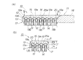
本実施形態の歯ブラシ10は、図1(a)、(b)に示すように、柄部18と、柄部18の先端側に連設され、ブリッスルを束ねてなる毛束14が複数植設された植毛部17とを有する歯ブラシであって、植毛部17は、背面側に立設する周縁壁19の内側の植毛用凹部20の底面20aに複数の植毛孔13が開口形成された植毛基部12と、植毛孔13に各々配置され、加熱溶融された片端部14a(図4参照)による溶融塊15を植毛用凹部20の底面20aに有する毛束14と、植毛基部12の周縁壁19の上端面19aと植毛用凹部20とを覆って成形された背面成形部16とを備える。図2(a)に示すように、植毛基部12の周縁壁19は、少なくとも植毛部17の先端部分に先端方向に突出して湾曲する湾曲周縁部21を備えており、植毛孔13は、植毛基部12の上から下に連通し断面積が概ね同じ筒部13bと、植毛用凹部20の底面20aに断面積をテーパー状に拡大させたテーパー状開口周縁部13aを備えている(図1(a)、(b)参照)。湾曲周縁部21を備える少なくとも先端部分の周縁壁19は、周縁壁19の近傍の1対の先端植毛孔13’,13’のテーパー状開口周縁部13a’,13a’の外縁の間の領域において、内側に肉厚が大きくなり、一対の植毛孔13’、13’の中間に相当する部分において最も肉厚が大きい厚肉部22を備えている。厚肉部22は、先端部分の周縁壁19の近傍の1対の先端植毛孔13’,13’の中間に相当する部分に向けて徐々に肉厚が大きく形成されていることが好ましく、さらに先端部分の周縁壁19の近傍の1対の先端植毛孔13’,13’のテーパー状開口周縁部13a’,13a’の外縁に沿った形状となるように形成されていることが好ましく、特に、植毛用凹部20の内側に突き出た中間凸部によって形成されていることが好ましい(図7参照)。ここで、周縁壁19における1対の先端植毛孔13’、13’の中間に相当する部分とは、一対の植毛孔13’、13’の中心を結ぶ線の中点から垂直に延びる線上の周縁壁19の部分をいう。
As shown in FIGS. 1 (a) and 1 (b), the
また、本実施形態では、湾曲周縁部21を備える先端部分の周縁壁19の近傍の1対の先端植毛孔13’,13’は、植毛基部12の長手方向中心線を対称軸とする対称位置に配置されるものが好ましいが、図9に示すように、先端部の植毛基部12の長手方向中心線上に植毛孔13’を設け、植毛孔13’の周方向両側の植毛孔13”、13”との間に厚肉部22を設けるものであってもよい。
In the present embodiment, the pair of
本実施形態では、図2(a)に示すように、湾曲周縁部21を備える先端部分の周縁壁19の内壁面を、当該先端部分の周縁壁19の近傍の1対の先端植毛孔13’,13’のテーパー状開口周縁部13a’,13a’と重ならない領域において形成する。具体的には、湾曲周縁部21を備える先端部分の周縁壁19の内壁面は、植毛基部12の長手方向中心線と垂直な面であって、湾曲周縁部21の弦方向に沿って起立して形成されることにより、周縁壁19の湾曲周縁部21を外側に拡幅させることなく、1対の先端植毛孔13’,13’のテーパー状開口周縁部13a’,13a’の外縁の間の領域において、植毛用凹部20の内側に向かって肉厚が大きくなった厚肉部22を形成している。
In this embodiment, as shown to Fig.2 (a), the inner wall surface of the
本発明の歯ブラシ10は、図2(b),(c)に示すように、先端部分において、前記植毛部17の外周面と、先端植毛孔13’の筒部13b’の内面の植毛部17と最も近い部分との間の距離d1は、先端部分において植毛部17の周縁と毛束14との間隔を狭くする観点から、0.5〜2mmであることが好ましく、さらに0.6〜1.5mmであることが好ましく、特に0.75〜1.25mmであることが好ましい。ここで、距離d1は、植毛基部12の下面であって歯ブラシ10の毛束14が出ている植毛表面、即ち背面成形部16と反対側の表面近傍にいて、Rが形成されていない植毛部17の外周面の位置から、先端植毛孔13’の筒部13b’との距離である。距離d1を短くすることによって、口腔内での歯ブラシ10の使用時に、植毛基部12の先端が届く位置と同程度まで毛束14が届くことになり、歯ブラシ10の操作性、特に奥歯を磨く際の操作性が良好になる。
As shown in FIGS. 2B and 2C, the
本発明の歯ブラシ10は、先端植毛孔13’だけでなく、 柄部近傍の後端部を除き、周縁壁19に沿って複数の植毛孔13が並んでいることが好ましく、さらに、周縁壁19に沿って並ぶ植毛孔13は、植毛部17の外周面と筒部13bの内面の植毛部17の外周面と最も近い部分との間の距離が0.5〜2mmであることが好ましく、さらに0.6〜1.5mmであることが好ましく、特に0.75〜1.25mmであることが好ましい。このように周縁壁19に沿わせながら近接して植毛孔13を並んで配置させることによって、口腔内での歯ブラシ10の操作性が良好になる。
In the
本実施形態の歯ブラシ10は、図3〜図6に示すように、例えば以下のような製造工程に従って製造される。すなわち、まず、先端部分に植毛基部12を備える図3(b)に示すような歯ブラシ本体11を形成する。歯ブラシ本体11を形成するには、図3(a)に示すように、歯ブラシ本体11の形態に対応したキャビティ31及びキャビティ31に通じる樹脂注入路32を有する成形金型30を用いる。そして、成形金型30を公知の射出成形装置(図示せず)にセットし、所定の射出成形圧で樹脂注入路32からキャビティ31内に熱可塑性樹脂を溶融状態で射出し、冷却した後に脱型する。成形金型30に所定の加工を施しておくことにより、成形された歯ブラシ本体11の植毛基部12の先端部分の湾曲周縁部21に、1対の先端植毛孔13’,13’のテーパー状開口周縁部13a’,13a’の外縁の間の部分において植毛用凹部20の内側に向けて肉厚が大きくなり、植毛孔13’、13’の中間において肉厚が最も大きい厚肉部22を、容易に形成することができる(図2(a)参照)。
The
ここで、歯ブラシ本体11を形成するための熱可塑性樹脂としては、従来から歯ブラシ本体に用いられている種々の熱可塑性樹脂を用いることができる。例えば、ポリプロピレン等のポリオレフィン、ポリカーボネート、ポリエチレンテレフタレート等のポリエステル、ポリメチルメタクリレート、アクリロニトリル−スチレン共重合体、アクリロニトリル−ブタジエン−スチレン共重合体を用いることができる。 Here, as a thermoplastic resin for forming the toothbrush main body 11, various thermoplastic resins conventionally used for the toothbrush main body can be used. For example, polyolefin such as polypropylene, polyester such as polycarbonate and polyethylene terephthalate, polymethyl methacrylate, acrylonitrile-styrene copolymer, and acrylonitrile-butadiene-styrene copolymer can be used.
次に、図4に示すように、形成された歯ブラシ本体11の植毛基部12の植毛孔13に、複数本のブリッスルを束ねてなる毛束14を挿入する。毛束14の挿入方法に特に制限はなく、挿入スリーブを用いた方法等、公知の種々の挿入方法を採用することができる。また、歯ブラシ本体11の植毛基部12を、毛束保持孔33を有する毛束保持治具34に位置決めした状態で毛束14を植毛孔13に各々挿入することにより、毛束14を整列配置した状態で各植毛孔13に容易に配設することが可能になる。本実施形態においては、植毛孔13の断面形状は楕円形状であってもよいが、図2(a)に示すように円形であることが好ましい。
Next, as shown in FIG. 4, a
ここで、毛束14を構成するブリッスルとしては、従来から用いられている通常の材質のものを使用することができるが、清掃性等の点から歯ブラシ本体11を形成する樹脂と異なる種類の樹脂が好ましく、ナイロン等のポリアミド、ポリブチレンテレフタレート等のポリエステル等によるブリッスルを用いることが好ましい。
Here, as the bristle that constitutes the
植毛基部12の植毛孔13に毛束14を挿入した後、図5に示すように、毛束14の植毛基部12の背面側に突出する部分である片端部14a(図4参照)を加熱して溶融塊15を形成する。片端部14aを加熱溶融するための加熱方法としては、例えばレーザー加熱装置を用いた非接触熱源で加熱する方法等、公知の各種の加熱方法を採用することができる。加熱装置の非接触熱源としては、レーザービームを照射するレーザー発振器や、光源から光を集光して照射するハロゲンランプ等を用いることができる。本実施形態では、レーザービームを照射することにより溶融塊15を形成した。
After inserting the
本実施形態では、植毛基部12の背面側の植毛用凹部20の底面20aには、断面積をテーパー状に拡大させた植毛孔13のテーパー状開口周縁部13aが形成されているので、このテーパー状開口周縁部13aのテーパー面に溶融塊15を強固に融着させて各植毛孔13を隙間無く塞ぐことにより、植毛基部12の背面側に被覆樹脂を充填して背面成形部16を成形する際に、充填圧力によって植毛孔13の隙間から樹脂が漏れ出るのを効果的に回避することが可能になるとともに、毛束14が溶融塊15によって一体化される。また、隣り合う植毛孔13同士の間隔の平均は、隣り合う植毛孔13の溶融塊15の周縁が連続又は近接し、植毛基部12の背面側から被覆樹脂を充填して背面成形部15を成形する際に、溶融塊15と植毛用凹部20の底面20aとの隙間から被覆樹脂が植毛孔13に漏れ出ることを抑制する観点から、0.3〜1.5mmであることが好ましく、0.5〜1.2mmであることが好ましく、特に0.7〜1.2mmであることが好ましい。特に先端部における隣り合う植毛孔13の間隔が0.3〜1.2mmであることが好ましく、さらに0.5〜1.1mmであることが好ましく、特に0.7〜1.1mmであることが好ましい。
In the present embodiment, since the tapered opening
植毛基部12の背面側に溶融塊15を形成したら、図6に示すように、植毛基部12の背面側に被覆樹脂を充填して、植毛基部12の周縁壁19の上端面19aと植毛用凹部20とを覆う背面成形部16を成形する。背面成形部16を形成するには、例えば毛束14を融着した歯ブラシ本体11の植毛基部12を背面部形成用の金型36に位置決めした後に、所定の充填圧力で、被覆樹脂を植毛基部12の背面側に充填する。被覆樹脂は、歯ブラシ本体11及び植毛基部12との一体性向上の点から、好ましくは歯ブラシ本体11及び植毛基部12に用いた熱可塑性樹脂と同じ樹脂を用いる。
When the
植毛基部12の背面側に充填した被覆樹脂が硬化して背面成形部16が成形されたら、背面部形成用の金型36から形成された植毛部17を取り外し、必要に応じてトリミング等の後工程の処理を行って、歯ブラシ10の製造を完了する。
When the coating resin filled on the back surface side of the
ここで、本実施形態では、成形金型30(図3(a)参照)を用いて形成された歯ブラシ本体11(図3(b)参照)の植毛基部12は、図1(a),(b)及び図2(a)に示すように、背面成形部16が重ねて成形される部分を当該植毛基部12として、先端から柄部18に最も近い植毛孔13の筒部13bの柄部18側の端部までの長手方向の長さLは10〜30mmであることが好ましく、さらに15〜25mmであるものが好ましい。また、長手方向と垂直な方向の横幅Bは6〜20mmとなる大きさの長円形の平面形状を有するように形成されるが、長軸方向が長さLとなる楕円形状であってもよく、横幅Bはさらに8〜15mmであることが好ましく、特に8〜12mmであることが好ましい。また、植毛基部12は、例えば厚みh1が0.8〜3mmであることが好ましく、さらに1〜2.5mmであることが好ましく、特に1.5〜2.2mmであることが好ましい。周縁壁19の高さh3は0.1〜1.5mmであることが好ましく、さらに0.4〜1.2mmであることが好ましい。そして、植毛基部12の下面から背面成形部16の上面までの厚みTは、歯ブラシの操作性の観点から1.6〜5mmであることが好ましく、さらに2〜4.5mmが好ましく、特に3〜4mmが好ましい。
Here, in this embodiment, the flocked
また、本実施形態の歯ブラシ本体11は、先端部分が先端方向に突出した湾曲形状になっており、しかも、植毛部17の厚みTである植毛基部12の下面から背面成形部16の上面までの厚みTは、歯ブラシ本体11の柄の近傍の厚みT1よりも先端部分の厚みT2の方が小さくなっていることが好ましい。T1とT2との差は、1mm以下であることが好ましく、0.2〜0.7mmであることが好ましい。先端部分において歯ブラシ本体11の厚みが薄くなることによって、歯ブラシ本体11を、奥歯の奥まで挿入しやすくなる。一方、歯ブラシ本体11の先端部分の厚みT2を小さくすると、背面成形部16の厚み(h3+h2)が小さくなる。そして、先端部における周縁壁19の天面の厚みbは、先端部における毛束14と周縁壁19との間隔を狭くする点から、厚肉部22が設けられていない、例えば、先端植毛孔13’,13’との間隔が最も近い部分の周縁壁19において、0.2〜0.45mmであることが好ましく、0.25〜0.4mmであることが好ましい。これに対して、先端部分の周縁壁19の厚肉部22において最も肉厚が大きい部分の肉厚sは、0.6〜1.5mmであることが好ましく、さらに0.65〜1.25mmであることが好ましい。
In addition, the toothbrush body 11 of the present embodiment has a curved shape with the tip portion protruding in the tip direction, and from the lower surface of the flocked
そして、上述の製造方法によって植毛部17が形成された、上述の構成を備える本実施形態の歯ブラシ10によれば、歯ブラシ10の先端部において毛束14と周縁壁19との間隔を狭くすることができるとともに、歯ブラシ10の厚みTを薄くすることが可能となり、優れた操作性を保持したまま、先端部分の強度を効果的に向上させるとともに、背面成形部16の成形樹脂が植毛孔13’から漏れることを防止することができる。
And according to the
すなわち、本実施形態の歯ブラシ10によれば、植毛基部12の周縁壁19は、植毛部17の先端部分に先端方向に突出して湾曲する湾曲周縁部21を備えており、この先端部分の周縁壁19は、周縁壁19の近傍の1対の先端植毛孔13’,13’のテーパー状開口周縁部13a’,13a’の外縁の間の部分において、内側に肉厚が大きくなり、植毛孔13’、13’の中間に相当する部分において最も肉厚が大きい厚肉部22を備えているので、特に歯ブラシ10の先端部分において、植毛部17の周縁と外周部分の毛束14との間の間隔を広げることなく、植毛基部12の周縁壁19の上端面の面積を増加させることが可能になり、これによって植毛基部12と背面成形部16との一体性を向上させることが可能になる。
That is, according to the
また、本実施形態では、特に歯ブラシ10の先端部分で植毛基部12の周縁壁19の厚肉部22の厚みが増加するのに伴って、植毛基部12の先端植毛孔13’,13’のテーパー状開口周縁部13a’,13a’の外縁と周縁壁19との間の距離が小さくなり、毛束14の片端部14aの溶融塊15の周縁が周縁壁19に近接又は連続するものとなり、背面成形部16を成形する際の被覆樹脂が溶融塊15の周縁より周縁壁19側において植毛用凹部20の底面20aと溶融塊15との間から植毛孔13’に漏れ出すことを抑制することができる。
Further, in the present embodiment, the taper of the
本実施形態では、厚肉部22は、湾曲周縁部21を備える歯ブラシ10の先端部分の周縁壁19に設けられている。従って、毛束14と歯ブラシの外周縁との距離d1を小さくしながら、植毛基部12と背面成形部16との一体性を向上し、しかも背面成形部16を成形する際の被覆樹脂が植毛孔13’から漏れだすことを効果的に防止することができる。特に、歯ブラシ10の先端部分の肉厚を薄くした場合であっても、先端部分における植毛基部12と背面成形部16との一体性(剥離強度)を確保できる。
In the present embodiment, the
図7は、歯ブラシ10の植毛部17を形成する際に用いる、植毛基部12’の好ましい他の実施形態を例示するものである。図7に示す植毛基部12’は、上記実施形態の植毛基部12と略同様の構成を備えているが、図7に示す植毛基部12’では、厚肉部22’は、湾曲周縁部21を備える少なくとも先端部分の周縁壁19の近傍の1対の植毛孔13’,13’のテーパー状開口周縁部13a’,13a’の外縁に沿った形状となるように、内側に突き出た中間凸部23によって形成されている。図7に示す植毛基部12’によれば、特に歯ブラシ10の先端部分において、周縁壁19の天面の面積を更に増加させることが可能になるので、上述の植毛基部12’と背面成形部16との一体性、剥離強度を向上させることができる。また、一対の植毛孔13’、13’に形成される溶融塊15は、先端側において溶融塊15の周縁が周縁壁19と連続するものとなり、溶融塊15と植毛用凹部20の底面20aとの間から背面成形部16を成形する際の被覆樹脂が漏れることを防止することができる。
FIG. 7 illustrates another preferred embodiment of the flocked
図8は、歯ブラシ10の植毛部17を形成する際に用いる、植毛基部12”の更に好ましい他の実施形態を例示するものである。図8に示す植毛基部12”は、上記実施形態の植毛基部12と略同様の構成を備えているが、図8に示す植毛基部12”では、湾曲周縁部21を備える先端部分の周縁壁19を含む、周縁壁19の全周に亘って、周縁壁19の近傍の各1対の植毛孔13,13のテーパー状開口周縁部13a,13aの外縁に沿った形状となるように、植毛用凹部20の内側に突き出た中間凸部24による厚肉部22”が形成されている。図8に示す植毛基部12”によれば、歯ブラシ10の先端部分のみならず、歯ブラシ10の全周に亘って周縁壁19の天面の面積を増加させることが可能になるので、上述の剥離強度を向上させる機能を、より一層効果的に発揮させることが可能になる。
FIG. 8 illustrates still another preferred embodiment of the flocked
図9は、歯ブラシ10の植毛部17を形成する際に用いる、植毛基部12xの更に好ましい他の実施形態を例示するものである。図9に示す植毛基部12xは、図2(a)に示す植毛基部12と略同様の構成を備えているが、図9に示す植毛基部12xでは、先端部の湾曲周縁部21を備える周縁壁19の先端に向けて突出する湾曲形状に対応して、植毛基部12xの長手方向にのびる中心軸上に植毛孔13’が形成され、植毛孔13’の両隣であって周縁壁19に沿う方向に並設された2つの植毛孔13”、13”が形成されている。そして、周縁壁19の厚肉部22xは、植毛孔13’と両側の植毛孔13”の間の領域の周縁壁19に各々形成されており、厚肉部22xは植毛孔13’と植毛孔13”との中央に相当する位置に向けて徐々に厚みが大きくなっている。これにより、先端部における植毛基部12xと背面成形部16との一体性を向上させる機能(剥離強度を向上させる機能)を発揮させることができると共に、植毛孔13’と植毛孔13”の溶融塊15の先端側において、溶融塊15の周縁が周縁壁19近傍か、または周縁壁19に連続させることが可能となり、樹脂漏れ抑制効果を向上することができる。
FIG. 9 illustrates another preferred embodiment of the flocked
なお、本発明は上記実施形態に限定されることなく種々の変更が可能である。例えば、植毛基部は、略長円形の平面形状を有するように形成されている必要は必ずしも無く、略円形や略楕円形等、少なくとも植毛部の先端部分に先端方向に突出する湾曲周縁部を備える、その他の種々の平面形状に形成することもできる。 The present invention is not limited to the above-described embodiment, and various modifications can be made. For example, the flocked base portion does not necessarily have to be formed to have a substantially oval planar shape, and includes a curved peripheral portion that protrudes in the distal direction at least at the distal end portion of the flocked portion, such as a substantially circular shape or a substantially oval shape. Other various planar shapes can also be formed.
以下、実施例及び比較例により、本発明の歯ブラシをさらに詳細に説明するが、本発明はこれらに限定されるものではない。 Hereinafter, although the toothbrush of this invention is demonstrated in detail by an Example and a comparative example, this invention is not limited to these.
図2(a)に示す植毛基部を備える歯ブラシ(実施例1)と、図8に示す植毛基部を備える歯ブラシ(実施例2)、及び図10に示す植毛基部を備える歯ブラシ(比較例1)について、先端部の剥離強度試験と、樹脂漏れ抑制のための評価を行った。
<各歯ブラシの構成>
実施例1の歯ブラシは図2(a)に表された構成であって、毛束はポリブチレンテレフタレートであり、植毛基部12、背面成形部16及び柄部18をポリプロピレンで成形した。また、植毛基部12の柄部18に最も近い植毛孔13の柄部18側の端部から、植毛基部12の先端までの距離Lが20mmであり、植毛基部12の短軸方向の幅B(最も広い幅B)が10mm、植毛基部11の植毛用凹部20の底面20aから植毛基部11の下面(背面成形部16と反対側の植毛面)までの平均厚みh1が2mm、周縁壁19の平均高さhが1mm、植毛基部11の下面(植毛面)から背面成形部16の上面までの厚みTが、柄部18の側における厚みT1が4mmであって、先端部における厚みT2が3.5mmである(図1(a),(b)参照)。植毛孔13の径は1.4mmであり、隣り合う植毛孔13の平均間隔は1mm、植毛孔13のテーパー状開口部の周縁の径が1.9mmであった。また、周縁壁の天面の幅bは厚肉部22が形成されていない部分において平均0.4mmであった。
実施例1の歯ブラシは、先端部の厚肉部22の厚みsは0.7mmであった。
実施例2の歯ブラシは、図8に表された構成であって、厚肉部22の形態と、厚肉部22を全周に形成した点を除けば実施例1と同じ構成であり、先端部の厚肉部22の幅sは1.23mmであった。
比較例1の歯ブラシは、図10に表された構成であって、厚肉部22を設けないことを除けば実施例1と同じ構成である。
About a toothbrush (Example 1) provided with the flocked base shown in FIG. 2 (a), a toothbrush (Example 2) provided with the flocked base shown in FIG. 8, and a toothbrush (Comparative Example 1) provided with the flocked base shown in FIG. The peel strength test at the tip and evaluation for resin leakage suppression were performed.
<Configuration of each toothbrush>
The toothbrush of Example 1 has the configuration shown in FIG. 2A, and the bristle bundle is polybutylene terephthalate, and the flocked
In the toothbrush of Example 1, the thickness s of the
The toothbrush of Example 2 is the structure shown in FIG. 8, Comprising: Except for the point which formed the
The toothbrush of the comparative example 1 is the structure represented by FIG. 10, Comprising: Except not providing the
<剥離強度試験>
剥離強度は、以下の方法により測定した。
(1)成形された歯ブラシ(図2、図8、図10に示す歯ブラシ)の先端部分の周縁壁19の近傍の1対の植毛孔13’,13’の毛束14を、溶融塊15から抜くようにペンチで引き抜いた。他の植毛孔13の毛束は、植毛基部12の面に沿ってカットした。
(2)植毛孔13’,13’を上に向け、背面成形部16を側面から押圧によって支えて水平に指示した。
(3)植毛孔13’,13’の両方に、植毛孔13’の孔径と概ね同一のピンを挿入し、ピンを介して上方から植毛基部12に対して圧力をかけた。圧力は計測スタンドに固定したデジタルフォースゲージ(株式会社イマダ 高性能型デジタルフォースゲージZP−1000N)によって測定し、植毛基部12が背面成形部16から剥離するときの荷重(kg)を測定した。
(4)表1には、各実施例、比較例について10本の歯ブラシの剥離強度の平均値を示した。
<Peel strength test>
The peel strength was measured by the following method.
(1) The
(2) The flock holes 13 ′ and 13 ′ were faced up, and the
(3) A pin substantially the same as the hole diameter of the flocked
(4) Table 1 shows the average peel strength of 10 toothbrushes for each of the examples and comparative examples.
<溶融塊の評価>
溶融塊の評価は、植毛孔13’,13’の毛束14の片端部の溶融塊15の周縁の状態を目視で観察することによって行った。毛束14の溶融塊15は、植毛基部12の先端部と溶融塊15の周縁において連続し、一体をなすことによって、背面成形体のために充填された樹脂が植毛孔13’,13’から漏れて植毛面に露出しにくくなる。そこで、先端部における溶融塊15の植毛孔13’の先端側の周縁と、周縁壁19との間の隙間の程度により評価した。実施例1、2及び比較例1の各々10本の歯ブラシの2つの植毛孔13’、13’、つまり20個の植毛孔13’について、溶融塊15の先端側が周縁壁と連続している植毛孔13’の個数を表1に示す。
<Evaluation of molten mass>
Evaluation of the molten lump was performed by visually observing the peripheral state of the
表1に実施例1、2及び比較例1の歯ブラシの剥離強度試験及び溶融塊の評価を示す。表1に示すように、実施例1、2の歯ブラシは、比較例1の歯ブラシに比較して剥離強度が高く、植毛基部12と背面成形部16との一体性が高いことが認められる。また、実施例1、2は溶融塊15の先端側において、溶融塊15の周縁が周縁壁19に届いており、背面成形部16の成形時において被覆成形樹脂が植毛孔13’,13’へ樹脂漏れするのを抑制することができる。
Table 1 shows the peel strength tests of the toothbrushes of Examples 1 and 2 and Comparative Example 1 and the evaluation of the molten mass. As shown in Table 1, it can be seen that the toothbrushes of Examples 1 and 2 have higher peel strength than the toothbrush of Comparative Example 1, and the integrity of the flocked

10 歯ブラシ
11 歯ブラシ本体
12,12’,12” 植毛基部
13 植毛孔
13’ 先端植毛孔
13a,13a’ テーパー状開口周縁部
13b,13b’ 筒部
14 毛束
14a 片端部
15 溶融塊
16 背面成形部
17 植毛部
18 柄部
19 周縁壁
20 植毛用凹部
20a 植毛用凹部の底面
21 湾曲周縁部
22,22’,22” 厚肉部
23,24 中間凸部
DESCRIPTION OF
Claims (5)
前記植毛部は、背面側に立設する周縁壁の内側の植毛用凹部の底面に複数の植毛孔が開口形成された植毛基部と、前記植毛孔に各々配置され、加熱溶融された片端部による溶融塊を前記植毛用凹部の底面上に有する前記毛束と、前記植毛基部の前記周縁壁の上端面と前記植毛用凹部とを覆って成形された背面成形部とを備え、
前記植毛基部の前記周縁壁は、前記植毛部の先端部分に先端方向に突出して湾曲する湾曲周縁部を備えており、
前記植毛孔は、前記植毛用凹部の底面に向けて断面積をテーパー状に拡大させたテーパー状開口周縁部を備えており、
前記湾曲周縁部を備える先端部分の前記周縁壁は、当該周縁壁の近傍の1対の植毛孔のテーパー状開口周縁部の外縁の間の領域において、植毛用凹部の内側に肉厚が大きくなり、前記一対の植毛孔の中間に相当する部分において最も肉厚が大きい厚肉部を備える歯ブラシ。 A toothbrush having a handle portion and a flocked portion continuously provided on the distal end side of the handle portion, in which a plurality of hair bundles formed by bundling bristles are planted,
The flocked portion is formed by a flocked base portion in which a plurality of flocked holes are formed in the bottom surface of a flocked concave portion on the inner side of a peripheral wall standing on the back side, and one end portion that is arranged in the flocked hole and heated and melted. The hair bundle having a molten mass on the bottom surface of the recessed portion for flocking, and a back molding portion formed so as to cover the upper end surface of the peripheral wall of the flocked base and the recessed portion for flocking,
The peripheral wall of the flocked base is provided with a curved peripheral portion that protrudes and curves in the front end direction at the front end portion of the flocked portion,
The flocking hole has a tapered opening peripheral edge with a cross-sectional area enlarged in a taper shape toward the bottom surface of the concave portion for flocking,
The peripheral wall of the distal end portion including the curved peripheral edge portion is thickened inside the recessed portion for flocking in a region between the outer edges of the tapered opening peripheral edge portions of the pair of flock holes in the vicinity of the peripheral wall. A toothbrush comprising a thick part having the largest thickness in a portion corresponding to the middle of the pair of flock holes.
The toothbrush according to any one of claims 1 to 4, wherein a thickness of the flocked portion is smaller at a tip portion than a thickness near the handle portion.
Priority Applications (1)
| Application Number | Priority Date | Filing Date | Title |
|---|---|---|---|
| JP2010267470A JP5650996B2 (en) | 2010-11-30 | 2010-11-30 | toothbrush |
Applications Claiming Priority (1)
| Application Number | Priority Date | Filing Date | Title |
|---|---|---|---|
| JP2010267470A JP5650996B2 (en) | 2010-11-30 | 2010-11-30 | toothbrush |
Publications (2)
| Publication Number | Publication Date |
|---|---|
| JP2012115445A true JP2012115445A (en) | 2012-06-21 |
| JP5650996B2 JP5650996B2 (en) | 2015-01-07 |
Family
ID=46499048
Family Applications (1)
| Application Number | Title | Priority Date | Filing Date |
|---|---|---|---|
| JP2010267470A Active JP5650996B2 (en) | 2010-11-30 | 2010-11-30 | toothbrush |
Country Status (1)
| Country | Link |
|---|---|
| JP (1) | JP5650996B2 (en) |
Cited By (5)
| Publication number | Priority date | Publication date | Assignee | Title |
|---|---|---|---|---|
| JP2016010510A (en) * | 2014-06-27 | 2016-01-21 | 小林製薬株式会社 | toothbrush |
| JP2016010511A (en) * | 2014-06-27 | 2016-01-21 | 小林製薬株式会社 | toothbrush |
| JP2016214785A (en) * | 2015-05-26 | 2016-12-22 | 合資会社三和歯ブラシ工業所 | Brush manufacturing method and brush |
| JP2020185447A (en) * | 2014-06-27 | 2020-11-19 | 小林製薬株式会社 | toothbrush |
| JP2020192302A (en) * | 2019-05-27 | 2020-12-03 | 株式会社Mtt | Toothbrush with sphere-shaped brush hair tips having inside and surface layer impregnated with calcium and manufacturing method therefor |
Citations (5)
| Publication number | Priority date | Publication date | Assignee | Title |
|---|---|---|---|---|
| US10004A (en) * | 1853-09-06 | Improvement in iron car-brakes | ||
| JP2003135154A (en) * | 2001-08-24 | 2003-05-13 | Kao Corp | Method of manufacturing toothbrush and toothbrush |
| JP2005065870A (en) * | 2003-08-21 | 2005-03-17 | Kao Corp | Brush and manufacturing method therefor |
| JP2005245719A (en) * | 2004-03-03 | 2005-09-15 | Kao Corp | Brush |
| JP2010167175A (en) * | 2009-01-26 | 2010-08-05 | Sunstar Inc | Toothbrush and method of manufacturing the same |
-
2010
- 2010-11-30 JP JP2010267470A patent/JP5650996B2/en active Active
Patent Citations (5)
| Publication number | Priority date | Publication date | Assignee | Title |
|---|---|---|---|---|
| US10004A (en) * | 1853-09-06 | Improvement in iron car-brakes | ||
| JP2003135154A (en) * | 2001-08-24 | 2003-05-13 | Kao Corp | Method of manufacturing toothbrush and toothbrush |
| JP2005065870A (en) * | 2003-08-21 | 2005-03-17 | Kao Corp | Brush and manufacturing method therefor |
| JP2005245719A (en) * | 2004-03-03 | 2005-09-15 | Kao Corp | Brush |
| JP2010167175A (en) * | 2009-01-26 | 2010-08-05 | Sunstar Inc | Toothbrush and method of manufacturing the same |
Cited By (8)
| Publication number | Priority date | Publication date | Assignee | Title |
|---|---|---|---|---|
| JP2016010510A (en) * | 2014-06-27 | 2016-01-21 | 小林製薬株式会社 | toothbrush |
| JP2016010511A (en) * | 2014-06-27 | 2016-01-21 | 小林製薬株式会社 | toothbrush |
| JP2020185447A (en) * | 2014-06-27 | 2020-11-19 | 小林製薬株式会社 | toothbrush |
| JP2016214785A (en) * | 2015-05-26 | 2016-12-22 | 合資会社三和歯ブラシ工業所 | Brush manufacturing method and brush |
| CN107708484A (en) * | 2015-05-26 | 2018-02-16 | 合资会社三和牙刷工业所 | The manufacture method and brush of brush |
| US10743651B2 (en) | 2015-05-26 | 2020-08-18 | Sanwa Tooth Brush Industrial Limited Partnership | Method of manufacturing a brush, and brush |
| CN107708484B (en) * | 2015-05-26 | 2020-12-22 | 合资会社三和牙刷工业所 | Brush manufacturing method and brush |
| JP2020192302A (en) * | 2019-05-27 | 2020-12-03 | 株式会社Mtt | Toothbrush with sphere-shaped brush hair tips having inside and surface layer impregnated with calcium and manufacturing method therefor |
Also Published As
| Publication number | Publication date |
|---|---|
| JP5650996B2 (en) | 2015-01-07 |
Similar Documents
| Publication | Publication Date | Title |
|---|---|---|
| US8297710B2 (en) | Toothbrush | |
| JP6669666B2 (en) | Brush head configuration | |
| JP5650996B2 (en) | toothbrush | |
| JP6629341B2 (en) | Brush head assembly and manufacturing method | |
| JP2020072789A (en) | toothbrush | |
| JP5224618B2 (en) | Brush manufacturing method and apparatus | |
| JPWO2017051777A1 (en) | toothbrush | |
| JP4862242B2 (en) | Toothbrush manufacturing method | |
| JP2000287755A (en) | Production of brush product | |
| JP4778167B2 (en) | Brush manufacturing method and apparatus | |
| JP4173749B2 (en) | Brush manufacturing method | |
| JP2008161271A (en) | Toothbrush and manufacturing method therefor | |
| JP2008194497A (en) | Implantation structure of hairs | |
| JP5290657B2 (en) | toothbrush | |
| CN114145560B (en) | Preparation method of brush head assembly | |
| JP2004254787A (en) | Brush | |
| JP2018198796A (en) | toothbrush | |
| JP2018108129A (en) | toothbrush | |
| WO2015137487A1 (en) | Toothbrush handle, toothbrush, and method for manufacturing toothbrush | |
| JPH1052316A (en) | Manufacture of brush | |
| JP4159381B2 (en) | toothbrush | |
| JP4393231B2 (en) | brush | |
| JP2008155051A (en) | Manufacturing method of brush | |
| JP2009034308A (en) | Toothbrush and its manufacturing method | |
| JP5412233B2 (en) | toothbrush |
Legal Events
| Date | Code | Title | Description |
|---|---|---|---|
| A621 | Written request for application examination |
Free format text: JAPANESE INTERMEDIATE CODE: A621 Effective date: 20130905 |
|
| A131 | Notification of reasons for refusal |
Free format text: JAPANESE INTERMEDIATE CODE: A131 Effective date: 20140617 |
|
| A521 | Request for written amendment filed |
Free format text: JAPANESE INTERMEDIATE CODE: A523 Effective date: 20140617 |
|
| A977 | Report on retrieval |
Free format text: JAPANESE INTERMEDIATE CODE: A971007 Effective date: 20140618 |
|
| TRDD | Decision of grant or rejection written | ||
| A01 | Written decision to grant a patent or to grant a registration (utility model) |
Free format text: JAPANESE INTERMEDIATE CODE: A01 Effective date: 20141111 |
|
| A61 | First payment of annual fees (during grant procedure) |
Free format text: JAPANESE INTERMEDIATE CODE: A61 Effective date: 20141114 |
|
| R151 | Written notification of patent or utility model registration |
Ref document number: 5650996 Country of ref document: JP Free format text: JAPANESE INTERMEDIATE CODE: R151 |
|
| R250 | Receipt of annual fees |
Free format text: JAPANESE INTERMEDIATE CODE: R250 |
|
| R250 | Receipt of annual fees |
Free format text: JAPANESE INTERMEDIATE CODE: R250 |
|
| R250 | Receipt of annual fees |
Free format text: JAPANESE INTERMEDIATE CODE: R250 |
|
| R250 | Receipt of annual fees |
Free format text: JAPANESE INTERMEDIATE CODE: R250 |
|
| R250 | Receipt of annual fees |
Free format text: JAPANESE INTERMEDIATE CODE: R250 |
|
| R250 | Receipt of annual fees |
Free format text: JAPANESE INTERMEDIATE CODE: R250 |
|
| R250 | Receipt of annual fees |
Free format text: JAPANESE INTERMEDIATE CODE: R250 |
|
| R250 | Receipt of annual fees |
Free format text: JAPANESE INTERMEDIATE CODE: R250 |