WO2015137487A1 - Toothbrush handle, toothbrush, and method for manufacturing toothbrush - Google Patents

Toothbrush handle, toothbrush, and method for manufacturing toothbrush Download PDF

Info

Publication number
WO2015137487A1
WO2015137487A1 PCT/JP2015/057481 JP2015057481W WO2015137487A1 WO 2015137487 A1 WO2015137487 A1 WO 2015137487A1 JP 2015057481 W JP2015057481 W JP 2015057481W WO 2015137487 A1 WO2015137487 A1 WO 2015137487A1
Authority
WO
WIPO (PCT)
Prior art keywords
toothbrush
handle
handle body
cavity
extending
Prior art date
Application number
PCT/JP2015/057481
Other languages
French (fr)
Japanese (ja)
Inventor
奥田 靖
Original Assignee
ライオン株式会社
Priority date (The priority date is an assumption and is not a legal conclusion. Google has not performed a legal analysis and makes no representation as to the accuracy of the date listed.)
Filing date
Publication date
Application filed by ライオン株式会社 filed Critical ライオン株式会社
Priority to CN201580013085.XA priority Critical patent/CN106102514A/en
Priority to KR1020167019599A priority patent/KR20160134643A/en
Priority to JP2016507847A priority patent/JPWO2015137487A1/en
Publication of WO2015137487A1 publication Critical patent/WO2015137487A1/en

Links

Images

Classifications

    • AHUMAN NECESSITIES
    • A46BRUSHWARE
    • A46BBRUSHES
    • A46B5/00Brush bodies; Handles integral with brushware
    • A46B5/002Brush bodies; Handles integral with brushware having articulations, joints or flexible portions
    • A46B5/0033Brush bodies; Handles integral with brushware having articulations, joints or flexible portions bending or stretching or collapsing
    • A46B5/0037Flexible resilience by plastic deformation of the material
    • AHUMAN NECESSITIES
    • A46BRUSHWARE
    • A46BBRUSHES
    • A46B5/00Brush bodies; Handles integral with brushware
    • AHUMAN NECESSITIES
    • A46BRUSHWARE
    • A46BBRUSHES
    • A46B5/00Brush bodies; Handles integral with brushware
    • A46B5/002Brush bodies; Handles integral with brushware having articulations, joints or flexible portions
    • A46B5/0033Brush bodies; Handles integral with brushware having articulations, joints or flexible portions bending or stretching or collapsing
    • A46B5/005Brushes with a telescopic or similarly moveable portion
    • AHUMAN NECESSITIES
    • A46BRUSHWARE
    • A46BBRUSHES
    • A46B5/00Brush bodies; Handles integral with brushware
    • A46B5/002Brush bodies; Handles integral with brushware having articulations, joints or flexible portions
    • A46B5/0054Brush bodies; Handles integral with brushware having articulations, joints or flexible portions designed to allow relative positioning of the head to body
    • A46B5/0062Brush bodies; Handles integral with brushware having articulations, joints or flexible portions designed to allow relative positioning of the head to body being flexible or resilient during use
    • AHUMAN NECESSITIES
    • A46BRUSHWARE
    • A46BBRUSHES
    • A46B9/00Arrangements of the bristles in the brush body
    • A46B9/02Position or arrangement of bristles in relation to surface of the brush body, e.g. inclined, in rows, in groups
    • A46B9/04Arranged like in or for toothbrushes

Landscapes

  • Brushes (AREA)

Abstract

This toothbrush handle (2) is of elongated shape having a handle portion (21), a neck portion (17) extending from the handle portion (21), and a head portion (11) situated at the distal end of the neck portion (17), wherein the toothbrush handle (2) is provided with a first member (10) that includes the head portion (11) and an extending portion (12) extending from the head portion (11), and with a second member (20) forming the handle portion (21), in which is formed a cavity (4) that extends in the lengthwise direction and opens at one end. Part of the extending portion (12) is inserted within the cavity (4), and an elastomer resin is arranged within the cavity (4), between the first member (10) and the second member (20).

Description

歯ブラシ用ハンドル体、歯ブラシ、及び歯ブラシ用ハンドル体の製造方法Toothbrush handle body, toothbrush, and method for manufacturing toothbrush handle body
 本発明は、歯ブラシ用ハンドル体、歯ブラシ、及び歯ブラシ用ハンドル体の製造方法に関する。
 本願は、2014年3月14日に、日本に出願された特願2014-051551号に基づき優先権を主張し、その内容をここに援用する。
The present invention relates to a toothbrush handle body, a toothbrush, and a method for manufacturing a toothbrush handle body.
This application claims priority on March 14, 2014 based on Japanese Patent Application No. 2014-051551 filed in Japan, the contents of which are incorporated herein by reference.
 歯ブラシとしては、ハンドル部、前記ハンドル部に延設されたネック部、及び前記ネック部の先端に設けられるヘッド部を備える歯ブラシ用ハンドル体と、前記ヘッド部に植毛された毛束とを備えるものが一般に知られている。歯ブラシ用ハンドル体において、通常、ネック部はハンドル部に対して縮径している。
 歯ブラシには、奥歯や前歯の裏側等をより擦掃しやすくするために、口腔内での操作性の向上が求められている。口腔内での操作性を高めた歯ブラシとしては、ヘッド部を小さくしたり、ヘッド部を薄くしたり、ネック部をさらに細くしたものが知られている。
 また、ハンドル部をエラストマー樹脂で被覆し、手指が滑るのを防止して、操作性の向上が図られた歯ブラシが知られている。
The toothbrush includes a handle portion, a handle portion for a toothbrush provided with a handle portion, a neck portion extended to the handle portion, and a head portion provided at the tip of the neck portion, and a hair bundle planted in the head portion. Is generally known. In a handle body for a toothbrush, the neck portion is usually reduced in diameter relative to the handle portion.
The toothbrush is required to improve operability in the oral cavity in order to make it easier to scrub the back teeth and the back side of the front teeth. As toothbrushes with improved operability in the oral cavity, those having a smaller head, a thinner head, or a thinner neck are known.
In addition, a toothbrush is known in which the handle portion is covered with an elastomer resin to prevent a finger from slipping and the operability is improved.
 一般に、歯ブラシ用ハンドル体は、ポリプロピレン(PP)等のポリオレフィンで構成されている。PP製の歯ブラシ用ハンドル体において、ヘッド部を小さくしたり、ヘッド部を薄くしたり、ネック部をさらに細くしたりすると、使用中にヘッド部やネック部が破損しやすくなる。また、平線式植毛で毛束を植毛した際にヘッド部が破損しやすくなる。
 これらの問題に対処するために、歯ブラシ用ハンドル体をポリアセタール樹脂(POM)等の高強度(曲げ弾性率2000MPa以上)の樹脂で成形した歯ブラシが提案されている(例えば、特許文献1)。
Generally, the handle body for toothbrushes is made of polyolefin such as polypropylene (PP). In a PP toothbrush handle body, if the head portion is made smaller, the head portion is made thinner, or the neck portion is made thinner, the head portion and the neck portion are likely to be damaged during use. In addition, the head portion is likely to be damaged when the hair bundle is planted with the flat wire type planting.
In order to cope with these problems, a toothbrush in which a handle body for a toothbrush is formed of a high-strength resin (bending elastic modulus of 2000 MPa or more) such as polyacetal resin (POM) has been proposed (for example, Patent Document 1).
 特許文献1の歯ブラシでは、機械的強度に優れるものの、ネック部の撓み量が小さいため、適切なブラッシング圧で清掃対象部位を擦掃できない。
 この問題に対し、特許文献2には、ネック部の断面輪郭をヘッド部からハンドル部に向かうに従い特定の形状に変化させ、ネック部の撓み方向を段階的に規制することにより、毛束を清掃対象部位に適切に当接させ、適切なブラッシング圧で清掃できる歯ブラシが開示されている。
Although the toothbrush of patent document 1 is excellent in mechanical strength, since the bending amount of a neck part is small, the site | part to be cleaned cannot be wiped off with appropriate brushing pressure.
To deal with this problem, Patent Document 2 discloses that a hair bundle is cleaned by changing the cross-sectional contour of the neck portion to a specific shape as it goes from the head portion toward the handle portion, and gradually regulating the bending direction of the neck portion. A toothbrush that can be appropriately brought into contact with a target portion and cleaned with an appropriate brushing pressure is disclosed.
特開平7-143914号公報Japanese Patent Laid-Open No. 7-143914 特開2013-118944号公報JP 2013-118944 A
 しかしながら、歯ブラシにおいて、ブラッシング圧がより適切にされ、より良好に擦掃できるものが望まれている。
 そこで、本発明は、使用時に、より適切なブラッシング圧で清掃対象部位を擦掃できる歯ブラシ用ハンドル体、歯ブラシ、及び歯ブラシ用ハンドル体の製造方法を目的とする。
However, a toothbrush that has a more appropriate brushing pressure and can be better removed is desired.
Therefore, an object of the present invention is to provide a toothbrush handle body, a toothbrush, and a method for manufacturing a toothbrush handle body that can scrub a site to be cleaned with a more appropriate brushing pressure during use.
 本発明者は、鋭意検討を重ねた結果、ヘッド部を備える第一の部材とハンドル部を備える第二の部材との間にエラストマー樹脂を設けることにより、ネック部の撓みに優れた歯ブラシ用ハンドル体が得られることを見出し、本発明を完成させた。
 すなわち、本発明は、以下の態様を有する。
[1]ハンドル部、前記ハンドル部に延設されたネック部、及び前記ネック部の先端に設けられたヘッド部を備え、長尺状とされた歯ブラシ用ハンドル体において、前記ヘッド部及び前記ヘッド部から延びる延設部が備えられた第一の部材と、前記ハンドル部を形成し、長尺方向に延び、かつ、一方に開口する壁部に囲まれた空洞部が形成された第二の部材とを備え、前記延設部の一部は、前記空洞部内に挿入されており、前記空洞部内には、前記第一の部材と前記第二の部材との間にエラストマー樹脂が設けられている歯ブラシ用ハンドル体。
[2]前記延設部には、長尺方向に交わる方向に突出する第一の凸部が設けられており、前記第一の凸部の先端が前記空洞部を囲う前記壁部の内面に接している、[1]に記載の歯ブラシ用ハンドル体。
[3]前記延設部には、長尺方向に交わる方向に突出する第二の凸部が設けられており、前記第二の凸部が前記空洞部を囲う前記壁部を貫通している、[1]又は[2]に記載の歯ブラシ用ハンドル体。
[4]前記延設部の端部には、延設方向に突出する第三の凸部が形成されており、前記第二の部材には、前記第三の凸部に対応する凹部が形成されている、[1]~[3]のいずれか一項に記載の歯ブラシ用ハンドル体。
[5][1]~[4]のいずれか一項に記載の歯ブラシ用ハンドル体と、前記ヘッド部に植毛されている毛束とを有する歯ブラシ。
[6]前記延設部の一部を、前記空洞部に挿入する第一の工程と、前記空洞部内の、前記第一の部材と前記第二の部材との間に、エラストマー樹脂を充填する第二の工程とを有する、[1]~[4]のいずれか一項に記載の歯ブラシ用ハンドル体の製造方法。
[7]前記第二の工程において、前記第一の部材と前記第二の部材との間に、エラストマー樹脂を充填するのと同時に、ハンドル部の一部を被覆する被覆部を形成する、[6]に記載の歯ブラシ用ハンドル体の製造方法。
As a result of intensive investigations, the present inventor has provided an elastomer resin between the first member having the head portion and the second member having the handle portion, so that the handle for the toothbrush is excellent in bending of the neck portion. It was found that a body was obtained and the present invention was completed.
That is, this invention has the following aspects.
[1] A toothbrush handle body having a handle portion, a neck portion extended to the handle portion, and a head portion provided at a tip of the neck portion, and the head portion and the head A first member provided with an extending part extending from the part, and a second part forming the handle part, extending in the longitudinal direction, and formed with a cavity part surrounded by a wall part opened to one side A part of the extended portion is inserted into the cavity, and an elastomer resin is provided between the first member and the second member in the cavity. Toothbrush handle body.
[2] The extension portion is provided with a first protrusion protruding in a direction intersecting with the longitudinal direction, and a tip of the first protrusion is formed on an inner surface of the wall portion surrounding the cavity portion. The toothbrush handle body according to [1], which is in contact.
[3] The extended portion is provided with a second convex portion protruding in a direction intersecting with the longitudinal direction, and the second convex portion penetrates the wall portion surrounding the cavity portion. , [1] or [2] toothbrush handle body.
[4] A third convex portion protruding in the extending direction is formed at an end of the extended portion, and a concave portion corresponding to the third convex portion is formed in the second member. The toothbrush handle body according to any one of [1] to [3].
[5] A toothbrush comprising the toothbrush handle body according to any one of [1] to [4], and a bristle bundled in the head portion.
[6] A first step of inserting a part of the extended portion into the cavity, and filling the elastomer resin between the first member and the second member in the cavity. A method for manufacturing a handle for a toothbrush according to any one of [1] to [4], comprising a second step.
[7] In the second step, between the first member and the second member, an elastomer resin is filled, and at the same time, a covering portion that covers a part of the handle portion is formed. 6] The manufacturing method of the handle body for toothbrushes of description.
 本発明によれば、使用時にネック部の撓みに優れた歯ブラシ用ハンドル体、歯ブラシ、及び歯ブラシ用ハンドル体の製造方法を提供できる。 According to the present invention, it is possible to provide a toothbrush handle body, a toothbrush, and a method for manufacturing a toothbrush handle body that are excellent in bending of the neck portion during use.
本発明の歯ブラシの一実施形態の側面図である。It is a side view of one Embodiment of the toothbrush of this invention. 図1の実施形態における歯ブラシ用ハンドル体を長尺方向に切断した断面図である。It is sectional drawing which cut | disconnected the toothbrush handle body in embodiment of FIG. 1 in the elongate direction. 図1の実施形態における第一の部材を長尺方向に切断した断面図である。It is sectional drawing which cut | disconnected the 1st member in embodiment of FIG. 1 in the elongate direction. 図1の実施形態における第二の部材を長尺方向に切断した断面図である。It is sectional drawing which cut | disconnected the 2nd member in embodiment of FIG. 1 in the elongate direction. 図1の実施形態における第一の部材と第二の部材の連結部位の一例を長尺方向に切断した部分断面図である。It is the fragmentary sectional view which cut | disconnected the example of the connection site | part of the 1st member and 2nd member in embodiment of FIG. 1 in the elongate direction. 図1の実施形態のA-A’断面図である。FIG. 2 is a sectional view taken along the line A-A ′ of the embodiment of FIG. 1. 図1の実施形態のB-B’断面図である。FIG. 2 is a B-B ′ sectional view of the embodiment of FIG. 1. 図1の実施形態のC-C’断面図である。FIG. 2 is a sectional view taken along the line C-C ′ of the embodiment of FIG. 1. 図1の実施形態のD-D’断面図である。FIG. 2 is a sectional view taken along the line D-D ′ of the embodiment of FIG. 1. 図1の実施形態のE-E’断面図である。FIG. 2 is an E-E ′ sectional view of the embodiment of FIG. 1. 図1の実施形態のF-F’断面図である。FIG. 2 is an F-F ′ cross-sectional view of the embodiment of FIG. 1. 図1の実施形態のG-G’断面図である。FIG. 2 is a G-G ′ sectional view of the embodiment of FIG. 1. 図1の実施形態のH-H’断面図である。FIG. 2 is an H-H ′ cross-sectional view of the embodiment of FIG. 1. 図1の実施形態における第一の部材と第二の部材の連結部位の他の例を長尺方向に切断した部分断面図である。It is the fragmentary sectional view which cut | disconnected the other example of the connection part of the 1st member in the embodiment of FIG. 1, and a 2nd member in the elongate direction.
<歯ブラシの一実施形態>
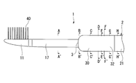
 本発明の歯ブラシは、歯ブラシ用ハンドル体と毛束とを備える。図1~6Hを参照して、本発明の一実施形態の歯ブラシ1を説明するが、本発明はこれに限定されるものではない。図1に示す歯ブラシ1は、長尺状のハンドル体2に、毛束40が設けられている。
<One Embodiment of Toothbrush>
The toothbrush of the present invention includes a toothbrush handle body and a hair bundle. A toothbrush 1 according to an embodiment of the present invention will be described with reference to FIGS. 1 to 6H, but the present invention is not limited to this. The toothbrush 1 shown in FIG. 1 is provided with a bristle bundle 40 on a long handle body 2.
[歯ブラシ用ハンドル体]
 図1に示すように、本実施形態の歯ブラシ用ハンドル体2は、ハンドル部21、前記ハンドル部21に延設されたネック部17、及び前記ネック部17の先端に設けられるヘッド部11を備え、ハンドル部21からヘッド部11の方向に長尺状である。ネック部17は、ハンドル部21に対して縮径している。本実施形態においては、ハンドル部21とネック部17の境を境界部3と称する。
 境界部3からハンドル部21側の外面及び第二の部材20の外面の一部は、被覆部32により被覆されている。
[Toothbrush handle]
As shown in FIG. 1, the toothbrush handle body 2 of this embodiment includes a handle portion 21, a neck portion 17 extending from the handle portion 21, and a head portion 11 provided at the tip of the neck portion 17. The shape is long in the direction from the handle portion 21 to the head portion 11. The neck portion 17 has a reduced diameter with respect to the handle portion 21. In the present embodiment, the boundary between the handle portion 21 and the neck portion 17 is referred to as a boundary portion 3.
A part of the outer surface on the handle part 21 side from the boundary part 3 and the outer surface of the second member 20 is covered with a covering part 32.
 本実施形態の歯ブラシ用ハンドル体2の長さは、特に限定されず、例えば、120~200mmとされる。
 ヘッド部11の幅は、特に限定されず、例えば、7~13mmが好ましく、8~12mmがより好ましい。上記下限値以上であれば、毛束40を植毛する面積を充分に確保でき、上記上限値以下であれば、口腔内での操作性をより高められる。ヘッド部の幅とは、長さ方向に対して垂直方向における、ヘッド部の端部から端部までの長さの最大値を意味する。
 ヘッド部11の長さは、特に限定されず、例えば、10~30mmが好ましく、12~28mmがより好ましい。上記下限値以上であれば、毛束40を植毛する面積を充分に確保でき、上記上限値以下であれば、口腔内での操作性をより高められる。なお、ヘッド部の長さとは、端部5側の毛束40のはえぎわからヘッド部先端までの長さを意味する。
 ヘッド部11の厚さは、材質等を勘案して決定でき、例えば、2~6mmが好ましく、2.5~4mmがより好ましい。上記下限値以上であれば、ヘッド部11の強度をより高められ、上記上限値以下であれば、口腔内での操作性をより高められる。ヘッド部の厚さとは、ヘッド部における厚さの最小値を意味する。
 ネック部17の太さは、材質等を勘案して決定でき、例えば、3~6mmが好ましく、3.5~4.5mmがより好ましい。上記下限値以上であれば、ネック部17の強度をより高められ、上記上限値以下であれば、口腔内での操作性をより高められる。ネック部の太さとは、長さ方向に対して垂直に切断したときの断面における直径の最小値を意味する。
The length of the toothbrush handle body 2 of the present embodiment is not particularly limited, and is, for example, 120 to 200 mm.
The width of the head portion 11 is not particularly limited, and is preferably 7 to 13 mm, and more preferably 8 to 12 mm, for example. If it is more than the said lower limit, the area which transplants the hair | bristle bundle 40 can fully be ensured, and if it is below the said upper limit, the operativity in an oral cavity will be improved more. The width of the head portion means the maximum value of the length from the end portion to the end portion in the direction perpendicular to the length direction.
The length of the head portion 11 is not particularly limited, and is preferably 10 to 30 mm, for example, and more preferably 12 to 28 mm. If it is more than the said lower limit, the area which transplants the hair | bristle bundle 40 can fully be ensured, and if it is below the said upper limit, the operativity in an oral cavity will be improved more. The length of the head portion means the length from the edge of the hair bundle 40 on the end portion 5 side to the tip of the head portion.
The thickness of the head portion 11 can be determined in consideration of the material and the like. For example, the thickness is preferably 2 to 6 mm, and more preferably 2.5 to 4 mm. If it is more than the said lower limit, the intensity | strength of the head part 11 can be raised more, and if it is below the said upper limit, the operativity in an intraoral area will be improved more. The thickness of the head portion means the minimum thickness of the head portion.
The thickness of the neck portion 17 can be determined in consideration of the material and the like, and is preferably 3 to 6 mm, and more preferably 3.5 to 4.5 mm. If it is more than the said lower limit, the intensity | strength of the neck part 17 can be raised more, and if it is below the said upper limit, the operativity in an intraoral area will be improved more. The thickness of the neck portion means the minimum value of the diameter in a cross section when cut perpendicular to the length direction.
 図2に示すように、本実施形態の歯ブラシ用ハンドル体2は、ヘッド部11及び前記ヘッド部11から延びる延設部12が備えられた第一の部材10と、ハンドル部21が形成された第二の部材20と、エラストマー樹脂からなる充填部31とを備える。ここで、延設部12の一部(第一の部材10の境界部3から端部5まで)は、空洞部4内に挿入されている。ネック部17は、延設部12のうち露出している部分である。具体的には、端部5側の毛束40のはえぎわから境界部3までの部分を意味する。また、充填部31は、空洞部4内の、第一の部材10と第二の部材20との間に設けられている。
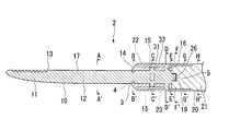
 なお、図2中のアルファベットは、図1のアルファベットが示す箇所に対応する箇所を示している。また、図2において、毛束40は省略されている。
As shown in FIG. 2, the handle body 2 for a toothbrush of the present embodiment is formed with a first member 10 having a head portion 11 and an extending portion 12 extending from the head portion 11, and a handle portion 21. A second member 20 and a filling portion 31 made of an elastomer resin are provided. Here, a part of the extending portion 12 (from the boundary portion 3 to the end portion 5 of the first member 10) is inserted into the cavity portion 4. The neck portion 17 is an exposed portion of the extended portion 12. Specifically, it means a portion from the edge of the hair bundle 40 on the end portion 5 side to the boundary portion 3. The filling portion 31 is provided between the first member 10 and the second member 20 in the cavity portion 4.
Note that the alphabets in FIG. 2 indicate locations corresponding to the locations indicated by the alphabets in FIG. Moreover, in FIG. 2, the hair | bristle bundle 40 is abbreviate | omitted.
 図3に示すように、本実施形態の第一の部材10において、ヘッド部11には植毛穴13が形成されている。図6A~6Eに示すように、延設部12は円柱状とされている。 As shown in FIG. 3, in the first member 10 of the present embodiment, a flock hole 13 is formed in the head portion 11. As shown in FIGS. 6A to 6E, the extending portion 12 has a cylindrical shape.
 図3、図6B~6D,6Fに示すように、第一の部材10の境界部3から延設部12の端部5までには、環状凹部14、第一の凸部15、第二の凸部16、第三の凸部19がこの順で設けられている。
 図3、図6Bに示すように、境界部3には、延設部12を周回する環状凹部14が形成されている。なお、環状凹部14は形成されていてもよく、形成されていなくてもよい。
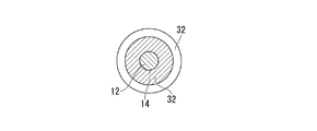
 図3、図6Cに示すように、第一の凸部15は、前記延設部12から、長尺方向に交わる方向で、毛束40側とその裏側の方向(図6Cの上下方向)、及び幅方向(図6Cの両横方向)の4方向に突出している。長尺方向に交わる方向とは、長さ方向に対して垂直方向であることを意味する。4方向に突出した第一の凸部を結ぶ対向線が、延設部12の中心を通るように設けられることが好ましい。4方向に突出した第一の凸部を結ぶ対向線が、垂直に交差することが好ましい。第一の凸部15は、延設部の周方向に同じ間隔で形成されていてもよいし、異なる間隔で形成されていてもよい。第一の凸部15の形状は、角柱状であってもよいし、円柱状であってもよい。
第一の凸部15は、その中心が境界部3から10~50mmの位置になるように形成されることが好ましい。第一の凸部15は、その中心が端部5から10~50mmの位置になるように形成されることが好ましい。
 図3、図6Dに示すように、第二の凸部16は、前記延設部12から、長尺方向に交わる方向で、毛束40側とその裏側の方向(図6Dの上下方向)の2方向に突出している。2方向に突出した第二の凸部を結ぶ線が、延設部12の中心を通るように設けられることが好ましい。第二の凸部16の形状は、角柱状であってもよいし、円柱状であってもよい。第二の凸部16は、第一の凸部15のうち毛束40側とその裏側の方向(図6Cの上下方向)に突出しているものと平行に突出していてもよいし、平行でなくてもよい。
第二の凸部16は、その中心が境界部3から20~80mmの位置になるように形成されることが好ましい。第二の凸部16は、その中心が端部5から10~50mmの位置になるように形成されることが好ましい。
 図3、図6Fに示すように、第三の凸部19は、端部5において、延設部12の延設方向に突出している。第三の凸部15の形状は、角柱状であってもよいし、円柱状であってもよい。
As shown in FIGS. 3 and 6B to 6D and 6F, an annular recess 14, a first protrusion 15, and a second protrusion 15 are formed from the boundary 3 of the first member 10 to the end 5 of the extended portion 12. A convex portion 16 and a third convex portion 19 are provided in this order.
As shown in FIGS. 3 and 6B, the boundary portion 3 is formed with an annular recess 14 that goes around the extending portion 12. In addition, the annular recessed part 14 may be formed and does not need to be formed.
As shown in FIG. 3 and FIG. 6C, the first convex portion 15 is a direction intersecting in the longitudinal direction from the extending portion 12, and the direction of the hair bundle 40 side and the back side thereof (vertical direction in FIG. 6C), And it protrudes in four directions of the width direction (both horizontal direction of FIG. 6C). The direction intersecting with the longitudinal direction means a direction perpendicular to the length direction. It is preferable that an opposing line connecting the first convex portions protruding in the four directions is provided so as to pass through the center of the extending portion 12. It is preferable that the opposing lines connecting the first protrusions protruding in the four directions intersect perpendicularly. The first convex portions 15 may be formed at the same interval in the circumferential direction of the extending portion, or may be formed at different intervals. The shape of the first convex portion 15 may be a prismatic shape or a cylindrical shape.
The first convex portion 15 is preferably formed so that the center thereof is positioned 10 to 50 mm from the boundary portion 3. The first convex portion 15 is preferably formed so that the center thereof is positioned 10 to 50 mm from the end portion 5.
As shown in FIGS. 3 and 6D, the second convex portion 16 extends from the extending portion 12 in the longitudinal direction in the direction of the hair bundle 40 side and the back side thereof (up and down direction in FIG. 6D). Projects in two directions. It is preferable that a line connecting the second protrusions protruding in two directions passes through the center of the extension part 12. The shape of the second convex portion 16 may be a prismatic shape or a cylindrical shape. The 2nd convex part 16 may protrude in parallel with what protrudes in the direction of the hair | bristle bundle 40 side and the back side (up-down direction of FIG. 6C) among the 1st convex parts 15, and is not parallel May be.
The second convex portion 16 is preferably formed so that the center thereof is positioned 20 to 80 mm from the boundary portion 3. The second convex portion 16 is preferably formed so that the center thereof is positioned 10 to 50 mm from the end portion 5.
As shown in FIGS. 3 and 6F, the third convex portion 19 protrudes in the extending direction of the extending portion 12 at the end portion 5. The shape of the third convex portion 15 may be a prismatic shape or a cylindrical shape.
 第一の部材10は、第一の樹脂で構成される。本実施形態において、第一の樹脂は、ヘッド部11やネック部17に求められる剛性や機械特性等を勘案して選択される。第一の樹脂としては、曲げ弾性率(JIS K7203)が500MPa以上3000MPa以下である樹脂が挙げられ、例えば、PBT、ポリエチレンテレフタレート(PET)、ポリシクロへキシレンジメチレンテレフタレート(PCT)等のポリエステル;POM;PP、ポリエチレン(PE)等のポリオレフィン;ポリスチレン(PS);アクリロニトリル・ブタジエン・スチレン樹脂(ABS)、セルロースプロピオネート(CP)、ポリアリレート、ポリカーボネート、アクリロニトリル・スチレン共重合樹脂(AS)等が挙げられる。中でも、ポリエステル及びPOMから選ばれる1種以上を主成分とする樹脂が好ましく、ポリエステル、POMがより好ましく、PBT、POMがさらに好ましい。ポリエステルやPOMであれば、剛性がより高いため、ヘッド部11をさらに薄くしても、充分な強度が得られる。これらの樹脂は、1種単独で用いられてもよいし、2種以上が組み合わされて用いられてもよい。なお、本明細書において「主成分」とは、50質量%以上を含有することをいう。 The first member 10 is made of a first resin. In the present embodiment, the first resin is selected in consideration of the rigidity and mechanical characteristics required for the head portion 11 and the neck portion 17. Examples of the first resin include resins having a flexural modulus (JIS K7203) of 500 MPa or more and 3000 MPa or less. For example, polyester such as PBT, polyethylene terephthalate (PET), polycyclohexylene dimethylene terephthalate (PCT); POM Polyolefins such as PP and polyethylene (PE); polystyrene (PS); acrylonitrile / butadiene / styrene resin (ABS), cellulose propionate (CP), polyarylate, polycarbonate, acrylonitrile / styrene copolymer resin (AS), etc. Can be mentioned. Among them, a resin mainly composed of one or more selected from polyester and POM is preferable, polyester and POM are more preferable, and PBT and POM are further preferable. Since polyester and POM have higher rigidity, sufficient strength can be obtained even if the head portion 11 is made thinner. These resins may be used alone or in combination of two or more. In the present specification, “main component” means containing 50% by mass or more.
 図4に示すように、本実施形態の第二の部材20は、ハンドル部21を形成し、長尺状である。また、第二の部材20には、ネック部17方向に開口部25を有する空洞部4が形成されている。前記空洞部4は、壁部22により囲われている。壁部22は、空洞部4に延設部12の一部(第一の部材10の境界部3から端部5まで)を挿入できるように形成されている。
 壁部22の毛束40側(図4の上側)とその裏側(図4の下側)には、開口部25(壁部22の先端)から後端(壁部22の付け根)に向かって延びるスリット23が形成されている。
 開口部25側から見た空洞部4の奥の壁面には、第一の凹部26が形成されている。第一の凹部26は、第三の凸部19に応じた形状とされている。
As shown in FIG. 4, the second member 20 of the present embodiment forms a handle portion 21 and has a long shape. The second member 20 is formed with a cavity 4 having an opening 25 in the direction of the neck 17. The cavity 4 is surrounded by a wall 22. The wall portion 22 is formed so that a part of the extending portion 12 (from the boundary portion 3 to the end portion 5 of the first member 10) can be inserted into the hollow portion 4.
On the hair bundle 40 side (upper side in FIG. 4) and the back side (lower side in FIG. 4) of the wall portion 22, from the opening 25 (front end of the wall portion 22) toward the rear end (root of the wall portion 22). An extending slit 23 is formed.
A first recess 26 is formed on the inner wall surface of the cavity 4 as viewed from the opening 25 side. The first concave portion 26 has a shape corresponding to the third convex portion 19.
 第二の部材2の太さは、被覆部32を設けるため、壁部22とその近傍が他の部分よりも一段細くなっている(図4、図6G、6H)。壁部22の近傍とは、ハンドル部において、壁部22側から10~50mmの部分を意味する。
 また、図4、図6F~6Hに示すように、第二の部材20は壁部22より後方が、円柱状とされている。ハンドル部の最も太い部分を幅方向に切断した断面における直径と、壁部22とその近傍において幅方向に切断した断面における直径との比が10:6~20:19であることが好ましい。
壁部の長さと、壁部22とその近傍部分との長さとの比は20:1~2:1であることが好ましい。
Since the thickness of the second member 2 is provided with the covering portion 32, the wall portion 22 and the vicinity thereof are thinner than the other portions (FIGS. 4, 6G, and 6H). The vicinity of the wall portion 22 means a portion of 10 to 50 mm from the wall portion 22 side in the handle portion.
Further, as shown in FIGS. 4 and 6F to 6H, the second member 20 has a columnar shape behind the wall portion 22. The ratio of the diameter of the cross section obtained by cutting the thickest part of the handle portion in the width direction to the diameter of the cross section cut in the width direction in the vicinity of the wall portion 22 is preferably 10: 6 to 20:19.
The ratio of the length of the wall portion to the length of the wall portion 22 and the vicinity thereof is preferably 20: 1 to 2: 1.
 第二の部材20は、第二の樹脂で構成される。本実施形態において、第二の樹脂は、ハンドル部21に求められる剛性、エラストマー樹脂との接着性等を勘案して決定される。
 第二の樹脂としては、例えば、第一の樹脂と同様のものが挙げられる。中でも、ポリオレフィンが好ましく、PPがより好ましい。ポリオレフィンであれば、第二の部材20とエラストマー樹脂との接着性を高められる。第二の樹脂は、第一の樹脂と同じでもよく、異なっていてもよい。
The second member 20 is made of a second resin. In the present embodiment, the second resin is determined in consideration of the rigidity required for the handle portion 21 and the adhesiveness with the elastomer resin.
Examples of the second resin include those similar to the first resin. Among these, polyolefin is preferable, and PP is more preferable. If it is polyolefin, the adhesiveness of the 2nd member 20 and elastomer resin can be improved. The second resin may be the same as or different from the first resin.
 本実施形態において、第一の樹脂と第二の樹脂との組み合わせとしては、第一の樹脂をポリエステル及びPOMから選ばれる1種以上を主成分とする樹脂とし、第二の樹脂をポリオレフィンとしたものが好ましく、第一の樹脂をPBT又はPOMとし、第二の樹脂をPPとしたものがより好ましい。このような組み合わせとすることで、ヘッド部11をより薄くし、延設部12をより細くして口腔内での操作性を高め、かつ第二の部材20とエラストマー樹脂との接着性を高められる。
 また、例えば、第一の樹脂を非透光性の樹脂とし、第二の樹脂を透光性の樹脂としてもよい。このような組み合わせとすることで、歯ブラシ用ハンドル体2の意匠のバリエーションを多様化できる。
In this embodiment, as a combination of the first resin and the second resin, the first resin is a resin mainly composed of one or more selected from polyester and POM, and the second resin is a polyolefin. The first resin is preferably PBT or POM, and the second resin is PP. By such a combination, the head portion 11 is made thinner, the extending portion 12 is made thinner to improve the operability in the oral cavity, and the adhesion between the second member 20 and the elastomer resin is improved. It is done.
Further, for example, the first resin may be a non-translucent resin and the second resin may be a translucent resin. By setting it as such a combination, the design variation of the toothbrush handle body 2 can be diversified.
 図2に示すように、第一の部材10の延設部12の一部は、空洞部4内に挿入されている。ネック部17は、延設部12のうち露出している部分(すなわち、延設部12のうち、境界部3から端部5までの部分を除いた部分)である。
 図2、図6Bに示すように、環状凹部14には、被覆部32を構成するエラストマー樹脂が設けられている。
 図2、図6Cに示すように、空洞部4内において、第一の凸部15の先端の全部又は一部は、壁部22の内面に当接している。これにより、後述する歯ブラシ1の製造方法の際に、壁部22に対する、第一の部材10の長尺方向に交わる方向の位置が決定し易くなる。なお、第一の凸部15は設けられていなくてもよい。第一の凸部15が設けられていない場合、使用する際、エラストマー樹脂からなる充填部31により第一の部材10の動きの柔軟性がより向上し、ブラッシング圧がより良好になる。第一の凸部15の先端が壁部22の内面に接している場合、第一の凸部15の先端の形状は壁部22の内面の形状に対応していることが好ましい。例えば、図6Cに示すように、壁部22の内面の幅方向で切断したときの断面形状が円弧状であれば、第一の凸部15の先端の幅方向で切断したときの断面形状も円弧状であることが好ましい。第一の凸部の高さ(厚さ)は0.1~2.0mmであることが好ましく、0.5~1.5mmであることがより好ましい。なお、充填部31の高さ(厚さ)と第一の凸部の高さ(厚さ)とは対応している。充填部31の高さ(厚さ)と壁部22の高さ(厚さ)との比は、 2:1~20:1であることが好ましい。
ネック部17の長さと、延設部12の一部(第一の部材10の境界部3から端部5まで)の長さとの比は、8:5~8:1であることが好ましい。
 図2、図6Dに示すように、第二の凸部16は、スリット23を通って壁部22を貫通している。前記第二の凸部16の先端は、被覆部32の外面と面一となっている。これにより、後述する歯ブラシ1の製造方法の際に、前記第二の凸部16の先端が金型に当接し、金型に対する、第一の部材10の長尺方向に交わる方向の位置が決定される。スリット23の幅は第二の凸部16の幅と同じであってもよいし、第二の凸部16の幅よりも広くてもよい。第二の凸部16の高さ(厚さ)は、充填部31の高さ(厚さ)、壁部22の高さ(厚さ)、及び被覆部32の高さ(厚さ)の合計と同じであることが好ましい。スリットの長さは、壁部22の長さと同じであってもよいし、異なっていてもよい。
As shown in FIG. 2, a part of the extending portion 12 of the first member 10 is inserted into the cavity portion 4. The neck portion 17 is an exposed portion of the extended portion 12 (that is, a portion of the extended portion 12 excluding a portion from the boundary portion 3 to the end portion 5).
As shown in FIGS. 2 and 6B, the annular recess 14 is provided with an elastomer resin that constitutes the covering portion 32.
As shown in FIGS. 2 and 6C, all or part of the tip of the first convex portion 15 is in contact with the inner surface of the wall portion 22 in the hollow portion 4. Thereby, in the case of the manufacturing method of the toothbrush 1 mentioned later, it becomes easy to determine the position of the direction which cross | intersects the longitudinal direction of the 1st member 10 with respect to the wall part 22. FIG. In addition, the 1st convex part 15 does not need to be provided. When the 1st convex part 15 is not provided, when using it, the softness | flexibility of the movement of the 1st member 10 improves more by the filling part 31 which consists of elastomer resins, and a brushing pressure becomes more favorable. When the tip of the first convex portion 15 is in contact with the inner surface of the wall portion 22, the shape of the tip of the first convex portion 15 preferably corresponds to the shape of the inner surface of the wall portion 22. For example, as shown in FIG. 6C, if the cross-sectional shape when cut in the width direction of the inner surface of the wall portion 22 is an arc shape, the cross-sectional shape when cut in the width direction of the tip of the first convex portion 15 is also An arc shape is preferred. The height (thickness) of the first convex portion is preferably 0.1 to 2.0 mm, and more preferably 0.5 to 1.5 mm. Note that the height (thickness) of the filling portion 31 corresponds to the height (thickness) of the first convex portion. The ratio of the height (thickness) of the filling portion 31 to the height (thickness) of the wall portion 22 is preferably 2: 1 to 20: 1.
The ratio of the length of the neck portion 17 to the length of a part of the extended portion 12 (from the boundary portion 3 to the end portion 5 of the first member 10) is preferably 8: 5 to 8: 1.
As shown in FIGS. 2 and 6D, the second convex portion 16 passes through the wall portion 22 through the slit 23. The tip of the second convex portion 16 is flush with the outer surface of the covering portion 32. Thereby, in the manufacturing method of the toothbrush 1 mentioned later, the front-end | tip of said 2nd convex part 16 contact | abuts to a metal mold | die, and the position of the direction which cross | intersects the elongate direction of the 1st member 10 with respect to a metal mold | die is determined. Is done. The width of the slit 23 may be the same as the width of the second protrusion 16 or may be wider than the width of the second protrusion 16. The height (thickness) of the second convex part 16 is the sum of the height (thickness) of the filling part 31, the height (thickness) of the wall part 22, and the height (thickness) of the covering part 32. Is preferably the same. The length of the slit may be the same as or different from the length of the wall portion 22.
 本実施形態においては、図2、図6Fに示すように、第三の凸部19が第一の凹部26に嵌め込まれた嵌め込み構造を形成している。
 嵌め込み構造は、図2、図6Fに示されるように、第三の凸部19が柱状の形状であり、第一の凹部26が前記形状に対応する形状とされている。
 この嵌め込み構造により、第二の部材20に対する、第一の部材10の長尺方向の位置が決定される。また、嵌め込み構造を採用すれば、第一の部材10の長尺方向に交わる方向へのずれが生じにくくなる。
In the present embodiment, as shown in FIGS. 2 and 6F, a fitting structure is formed in which the third convex portion 19 is fitted into the first concave portion 26.
In the fitting structure, as shown in FIGS. 2 and 6F, the third convex portion 19 has a columnar shape, and the first concave portion 26 has a shape corresponding to the shape.
With this fitting structure, the position of the first member 10 in the longitudinal direction with respect to the second member 20 is determined. Moreover, if the fitting structure is employed, the first member 10 is less likely to be displaced in the direction intersecting the longitudinal direction.
 また、嵌め込み構造はアンダーカット構造としてもよい。
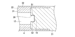
 アンダーカット構造とは、例えば、図5に示すように、第一の部材10の第三の凸部19が柱状の形状であり、前記柱状の形状の側面の周方向に第四の凸部51が設けられ、第二の部材20の凹部の内面の周方向に第四の凸部51に対応する第二の凹部52が設けられる構造等をいう。
 この場合、第四の凸部51は第二の凹部52に挿入されていることにより、第一の部材10は長尺方向に交わる方向だけでなく長尺方向にもずれが生じにくくなる。また、アンダーカット構造を採用すれば、第一の部材10と第二の部材20との連結をより強固にでき、使用時に第一の部材10が第二の部材20から抜け出るのをより防げる。
Further, the fitting structure may be an undercut structure.
For example, as illustrated in FIG. 5, the undercut structure is such that the third protrusion 19 of the first member 10 has a columnar shape, and the fourth protrusion 51 in the circumferential direction of the side surface of the columnar shape. Is provided, and the second concave portion 52 corresponding to the fourth convex portion 51 is provided in the circumferential direction of the inner surface of the concave portion of the second member 20.
In this case, since the fourth convex portion 51 is inserted into the second concave portion 52, the first member 10 is less likely to be displaced not only in the direction intersecting the longitudinal direction but also in the longitudinal direction. Moreover, if an undercut structure is employ | adopted, the connection of the 1st member 10 and the 2nd member 20 can be strengthened more, and it can prevent that the 1st member 10 slips out of the 2nd member 20 at the time of use.
 図2、図6C~Eに示すように、空洞部4内の、第一の部材10と第二の部材20との間には、充填部31が設けられている。前記充填部31は、エラストマー樹脂からなる。すなわち、空洞部4内の、第一の部材10と第二の部材20との間には、エラストマー樹脂が設けられている。
 ここで、「空洞部4内の、第一の部材10と第二の部材20との間」とは、図6C~6Eに示す延設部12と壁部22の間のことである。
As shown in FIGS. 2 and 6C to E, a filling portion 31 is provided between the first member 10 and the second member 20 in the cavity portion 4. The filling portion 31 is made of an elastomer resin. That is, an elastomer resin is provided between the first member 10 and the second member 20 in the cavity 4.
Here, “between the first member 10 and the second member 20 in the cavity 4” is between the extended portion 12 and the wall portion 22 shown in FIGS. 6C to 6E.
 充填部31を構成するエラストマー樹脂の種類としては、例えば、オレフィン系エラストマー、スチレン系エラストマー、ポリエステル系エラストマー、ポリウレタン系熱可塑性エラストマー等が挙げられる。中でも、スチレン系エラストマーが好ましい。スチレン系エラストマーは弾力性が特に優れているため、口腔内での操作性及び磨き心地をより高めることができる。これらの樹脂は、1種単独で用いられてもよいし、2種以上が組み合わされて用いられてもよい。エラストマー樹脂のショア硬度は、10~60が好ましい。なお、ショア硬度はJIS K 6253 ショアAの方法で測定することができる。 Examples of the type of elastomer resin constituting the filling portion 31 include olefin-based elastomers, styrene-based elastomers, polyester-based elastomers, polyurethane-based thermoplastic elastomers, and the like. Of these, styrene-based elastomers are preferable. Since the styrene elastomer is particularly excellent in elasticity, the operability in the oral cavity and the polishing comfort can be further enhanced. These resins may be used alone or in combination of two or more. The Shore hardness of the elastomer resin is preferably 10-60. The Shore hardness can be measured by the method of JIS K 6253 Shore A.
 図2、図6B~6Gに示すように、ハンドル部21には壁部22を含む領域に被覆部32が設けられている。
 前記被覆部32は、充填部31と同様にエラストマー樹脂からなる。被覆部32を構成するエラストマー樹脂の種類は、充填部31を構成するエラストマー樹脂と同様である。
As shown in FIGS. 2 and 6B to 6G, the handle portion 21 is provided with a covering portion 32 in a region including the wall portion 22.
The covering portion 32 is made of an elastomer resin, like the filling portion 31. The type of elastomer resin that constitutes the covering portion 32 is the same as that of the elastomer resin that constitutes the filling portion 31.
 本実施形態において、充填部31と被覆部32とは、スリット23及び開口部25を通じて接続している。
 第一の部材10と第二の部材20とは、主として、充填部31と被覆部32とが開口部25及びスリット23を通じての接続、エラストマー樹脂と第二の部材20の間における接着力又は摩擦力等により、強固に連結される。
In the present embodiment, the filling portion 31 and the covering portion 32 are connected through the slit 23 and the opening portion 25.
The first member 10 and the second member 20 are mainly composed of a connection between the filling portion 31 and the covering portion 32 through the opening 25 and the slit 23, and an adhesive force or friction between the elastomer resin and the second member 20. It is firmly connected by force.
[毛束]
 図1に示すように、本実施形態の歯ブラシ1は、上述した歯ブラシ用ハンドル体2と、ヘッド部11に植毛されている複数の毛束40とを有する。具体的には、毛束40は図2に示す植毛穴13に植毛されている。
 毛束40は、複数の用毛を束ねたものである。
 ヘッド部11の植毛面から毛束40の先端までの長さ(毛丈)は、毛束40に求める毛腰等を勘案して決定でき、例えば、6~13mmとされる。
 全ての毛束40は同じ毛丈であってもよいし、相互に異なっていてもよい。
[Hair bundle]
As shown in FIG. 1, the toothbrush 1 of the present embodiment includes the above-described toothbrush handle body 2 and a plurality of hair bundles 40 planted in the head portion 11. Specifically, the hair bundle 40 is implanted in the flock hole 13 shown in FIG.
The hair bundle 40 is a bundle of a plurality of hairs.
The length (hair length) from the flocked surface of the head portion 11 to the tip of the hair bundle 40 can be determined in consideration of the hair and the like required for the hair bundle 40, and is, for example, 6 to 13 mm.
All the hair bundles 40 may have the same hair length or may be different from each other.
 毛束40の太さ(毛束径)は、毛束40に求める毛腰等を勘案して決定でき、例えば、1~3mmとされる。全ての毛束40は同じ毛束径であってもよいし、相互に異なっていてもよい。 The thickness (hair bundle diameter) of the hair bundle 40 can be determined in consideration of the hair and the like required for the hair bundle 40, and is, for example, 1 to 3 mm. All the hair bundles 40 may have the same hair bundle diameter or may be different from each other.
 毛束40を構成する用毛としては、例えば、毛先に向かって漸次その径が小さくなり、毛先が先鋭化された用毛(テーパー毛)、植毛面から毛先に向かいその径がほぼ同一である用毛(ストレート毛)等が挙げられる。ストレート毛としては、毛先が植毛面に略平行な平面とされたものや、毛先が半球状に丸められたものが挙げられる。
一つの毛束を形成する用毛の本数は10~180本であることが好ましい。
As the hair constituting the hair bundle 40, for example, the diameter gradually decreases toward the hair tip, the hair having a sharp hair tip (tapered hair), and the diameter is approximately from the flocked surface toward the hair tip. The hair for the same (straight hair) etc. are mentioned. Examples of the straight hair include those in which the hair tip is a flat surface substantially parallel to the flocked surface and those in which the hair tip is rounded into a hemisphere.
The number of hairs for forming one hair bundle is preferably 10 to 180.
 用毛の材質は、例えば、6-12ナイロン(6-12NY)、6-10ナイロン(6-10NY)等のポリアミド、PET、PBT、ポリトリメチレンテレフタレート(PTT)、ポリエチレンナフタレート(PEN)、ポリブチレンナフタレート(PBN)等のポリエステル、PP等のポリオレフィン、ポリオレフィン系エラストマー、スチレン系エラストマー等のエラストマー樹脂等が挙げられる。
 これらの樹脂材料は、1種単独で又は2種以上を組み合わせて用いることができる。
 また、用毛としては、芯部と前記芯部の外側に設けられた少なくとも1層以上の鞘部とを有する多重芯構造を有するポリエステル製用毛が挙げられる。
The material of the hair is, for example, polyamide such as 6-12 nylon (6-12NY), 6-10 nylon (6-10NY), PET, PBT, polytrimethylene terephthalate (PTT), polyethylene naphthalate (PEN), Examples thereof include polyesters such as polybutylene naphthalate (PBN), polyolefins such as PP, elastomer resins such as polyolefin elastomers and styrene elastomers.
These resin materials can be used singly or in combination of two or more.
Examples of the bristle include polyester bristle having a multi-core structure having a core part and at least one or more sheath parts provided outside the core part.
 用毛の横断面形状は、特に限定されず、真円形、楕円形等の円形、多角形、星形、三つ葉のクローバー形、四つ葉のクローバー形等としてもよい。全ての用毛の断面形状は同じであってもよいし、異なっていてもよい。 The cross-sectional shape of the hair is not particularly limited, and may be a circle such as a perfect circle or an ellipse, a polygon, a star, a three-leaf clover, a four-leaf clover, or the like. The cross-sectional shapes of all the hairs may be the same or different.
 用毛の太さは、材質等を勘案して決定でき、横断面が円形の場合、例えば、6~9mil(1mil=1/1000inch=0.025mm)とされる。また、使用感、刷掃感、清掃効果、耐久性等を考慮して、太さの異なる複数本の用毛を任意に組み合わせて用いてもよい。 The thickness of the hair can be determined in consideration of the material and the like, and when the cross section is circular, for example, 6 to 9 mil (1 mil = 1/1000 inch = 0.025 mm). Moreover, in consideration of a feeling of use, a feeling of cleaning, a cleaning effect, durability, and the like, a plurality of hairs having different thicknesses may be used in any combination.
[製造方法]
 歯ブラシ1の製造方法は、第一の部材10と第二の部材20を別々に成形した後、インサート成形等で歯ブラシ用ハンドル体2を成形する。例えば、第一の部材10の延設部12の一部を、第二の部材20の空洞部4に挿入する第一の工程と、充填部31に、エラストマー樹脂を充填する第二の工程とにより、歯ブラシ用ハンドル体2を得る。
 次いで、前記歯ブラシ用ハンドル体2のヘッド部11に、毛束40を植毛して、歯ブラシ1が得られる。
[Production method]
In the manufacturing method of the toothbrush 1, after the first member 10 and the second member 20 are separately formed, the toothbrush handle body 2 is formed by insert molding or the like. For example, a first step of inserting a part of the extended portion 12 of the first member 10 into the cavity portion 4 of the second member 20, and a second step of filling the filling portion 31 with an elastomer resin. Thus, the toothbrush handle body 2 is obtained.
Next, the hair bundle 40 is implanted in the head portion 11 of the toothbrush handle body 2 to obtain the toothbrush 1.
 第一の部材10と第二の部材20は、射出成形等の公知の成形方法により得ればよい。
 以下、第二の工程をインサート成形で行う場合の、本発明の歯ブラシ1の製造方法の一例を説明する。
 まず、第二の部材20を金型内に配置する。この金型の内部では、第一の部材10及び第二の部材20を配置した状態において、被覆部32に応じた形状のキャビティが形成される。
 次いで、第一の部材10の延設部12の一部(第一の部材10の境界部3から端部5まで)を、第二の凸部16がスリット23内を移動するように第二の部材20の空洞部4に挿し込み(第一の工程)、第三の凸部19の先端が第二の部材20の第一の凹部26に嵌める。
 次いで、金型を閉じる。第一の部材10及び第二の部材20を金型内に配置すると、第一の凸部15が第二の部材20の壁部22の内面に当接し、第二の凸部16の壁部22外に突き出した先端が金型に当接するため、エラストマー樹脂を射出した際に、第一の部材10がずれにくい。
The first member 10 and the second member 20 may be obtained by a known molding method such as injection molding.
Hereinafter, an example of the manufacturing method of the toothbrush 1 of this invention when performing a 2nd process by insert molding is demonstrated.
First, the second member 20 is placed in the mold. Inside the mold, a cavity having a shape corresponding to the covering portion 32 is formed in a state where the first member 10 and the second member 20 are arranged.
Next, a part of the extended portion 12 of the first member 10 (from the boundary portion 3 to the end portion 5 of the first member 10) is moved so that the second convex portion 16 moves in the slit 23. Is inserted into the cavity 4 of the member 20 (first step), and the tip of the third protrusion 19 is fitted into the first recess 26 of the second member 20.
The mold is then closed. When the first member 10 and the second member 20 are arranged in the mold, the first convex portion 15 comes into contact with the inner surface of the wall portion 22 of the second member 20, and the wall portion of the second convex portion 16. Since the tip protruding outside 22 contacts the mold, the first member 10 is not easily displaced when the elastomer resin is injected.
 次いで、金型の内部に第一の部材10及び第二の部材20を配置した状態でエラストマー樹脂を金型内に射出する。金型内に射出されたエラストマー樹脂は、スリット23、開口部25を通って、充填部31に充填される(第二の工程)。また、ハンドル部21の一部及び壁部22の外側を被覆する被覆部32が、所望の厚さで形成される。充填部31と被覆部32にエラストマー樹脂が設けられることにより、第一の部材10と第二の部材20とが互いに固定される。
エラストマー樹脂を金型内に射出する際の、金型の温度は20~80℃であることが好ましい。
Next, the elastomer resin is injected into the mold in a state where the first member 10 and the second member 20 are disposed inside the mold. The elastomer resin injected into the mold passes through the slit 23 and the opening 25 and fills the filling portion 31 (second step). Moreover, the coating | coated part 32 which coat | covers a part of handle part 21 and the outer side of the wall part 22 is formed by desired thickness. The first member 10 and the second member 20 are fixed to each other by providing the filling portion 31 and the covering portion 32 with the elastomer resin.
The temperature of the mold when the elastomer resin is injected into the mold is preferably 20 to 80 ° C.
 さらに毛束40を植毛穴13に植毛する工程(第三の工程)を行うことにより、歯ブラシを形成する。第三の工程は、第二の工程の後に行ってもよいし、第一の工程の前に行ってもよい。毛束40の植毛方法としては、毛束40を二つ折りにしその間に挟み込まれた平線を植毛穴13に打ち込むことにより毛束40を植毛する平線式植毛、毛束40の下端を植毛穴13となる溶融樹脂中へ圧入して固定する熱融着法、毛束40の下端を加熱して溶融塊を形成した後に金型中に溶融樹脂を注入して植毛穴13を成形するインモールド法等が挙げられる。 Further, a toothbrush is formed by performing a step (third step) of flocking the hair bundle 40 in the flock hole 13. The third step may be performed after the second step or may be performed before the first step. As a method for flocking the hair bundle 40, the hair bundle 40 is folded in half, and a flat wire sandwiched between the two is driven into the flock hole 13 so that the hair bundle 40 is planted. In-mold in which a fusing hole 13 is formed by injecting the molten resin into a mold after the lower end of the hair bundle 40 is heated to form a molten lump. Law.
 上述の通り、本実施形態によれば、エラストマー樹脂からなる充填部31が設けられるため、適切なブラッシング圧で清掃することができる歯ブラシ用ハンドル体2及び歯ブラシ1が得られる。これは、充填部31に柔軟性が高い樹脂であるエラストマー樹脂が用いられることにより、使用時のブラッシング圧が緩和されることによる。
 したがって、本実施形態の歯ブラシ1を用いれば、毛束40を清掃対象部位に適切に当接させ、適切なブラッシング圧で清掃することができるため、擦掃効果がより高くなる。
As described above, according to the present embodiment, since the filling portion 31 made of an elastomer resin is provided, the toothbrush handle body 2 and the toothbrush 1 that can be cleaned with an appropriate brushing pressure are obtained. This is because the use of an elastomer resin, which is a highly flexible resin, in the filling portion 31 reduces the brushing pressure during use.
Therefore, if the toothbrush 1 of this embodiment is used, since the bristle bundle 40 can be appropriately brought into contact with the site to be cleaned and cleaned with an appropriate brushing pressure, the scrubbing effect is further enhanced.
 本実施例によれば上述の擦掃効果が得られるため、ヘッド部11を小さくしたり、ヘッド部11を薄くしたり、ネック部17をさらに細くしたりするために、第一の部材10にPOM等の高強度の樹脂を用いても、より適切なブラッシング圧で清掃することができ、良好な擦掃効果が得られる。
 また、本実施形態において、第一の部材10にPOM等の高強度の樹脂を用いれば、平線式植毛で毛束40を植毛した際のヘッド部11の破損、ヘッド部11の強度の低下による使用中におけるヘッド部11の破損を防ぐことができる。
According to the present embodiment, since the above-described scavenging effect is obtained, the first member 10 is formed in order to make the head portion 11 small, the head portion 11 thin, or the neck portion 17 further narrowed. Even if a high-strength resin such as POM is used, cleaning can be performed with a more appropriate brushing pressure, and a good scrubbing effect can be obtained.
In the present embodiment, if a high-strength resin such as POM is used for the first member 10, the head portion 11 is damaged when the hair bundle 40 is implanted by flat-wire-type flocking, and the strength of the head portion 11 is reduced. It is possible to prevent damage to the head portion 11 during use.
 本実施形態の製造において、金型内に第一の部材10と第二の部材20とを配置すると、第一の凸部15が壁部22の内面に当接し、また、スリット23を通って壁部22を貫通している第二の凸部16の先端が金型に当接するため、エラストマー樹脂を射出した際に、第一の部材10が長尺方向に交わる方向に生じ得るずれが起こりにくい。
 また、本実施形態の延設部12の境界部3から端部5までの間に、例えば、毛束40側とその裏側の方向に、エラストマー樹脂が通り抜けできるような貫通孔を形成することで、製造の際、エラストマー樹脂が充填しやすくなる。また、この貫通孔内にエラストマー樹脂が設けられることにより、第一の部材10と第二の部材20との連結がさらに強固になる。
In the manufacture of the present embodiment, when the first member 10 and the second member 20 are arranged in the mold, the first convex portion 15 comes into contact with the inner surface of the wall portion 22 and passes through the slit 23. Since the tip of the second convex portion 16 penetrating the wall portion 22 comes into contact with the mold, a deviation that may occur in the direction in which the first member 10 intersects the longitudinal direction occurs when the elastomer resin is injected. Hateful.
In addition, by forming a through-hole through which the elastomer resin can pass between the boundary portion 3 and the end portion 5 of the extending portion 12 of the present embodiment, for example, in the direction of the hair bundle 40 side and the back side thereof. During production, the elastomer resin is easily filled. Further, by providing the elastomer resin in the through hole, the connection between the first member 10 and the second member 20 is further strengthened.
<他の実施形態>
 本発明は、上述の実施形態に限定されるものではない。
 上述の実施形態において、第一の凸部15は設けられていてもよく、設けられていなくてもよい。製造する際、第二の部材20に対して第一の部材10を所望の位置に固定するため、第一の凸部15が設けられていることが好ましく、少なくとも2箇所設けられていることがより好ましい。少なくとも4か所設けられていることがさらに好ましい。
 上述の実施形態において、第二の凸部16は設けられていてもよく、設けられていなくてもよい。製造する際、金型に対して所望の位置に固定するため、第二の凸部16が設けられていることが好ましく、少なくとも2箇所設けられていることがより好ましい。
<Other embodiments>
The present invention is not limited to the embodiment described above.
In the above-mentioned embodiment, the 1st convex part 15 may be provided and does not need to be provided. When manufacturing, in order to fix the first member 10 to a desired position with respect to the second member 20, it is preferable that the first convex portion 15 is provided, and that at least two locations are provided. More preferred. More preferably, at least four places are provided.
In the above-mentioned embodiment, the 2nd convex part 16 may be provided and does not need to be provided. When manufacturing, in order to fix to a desired position with respect to a metal mold | die, it is preferable that the 2nd convex part 16 is provided, and it is more preferable that at least 2 places are provided.
 上述の実施形態においては、第三の凸部19と第一の凹部26とにより形成される嵌め込み構造において、第三の凸部19の先端以外の端部5が第二の部材20に当接しないようにし、隙間を設ければ(図7を参照)、エラストマー樹脂が隙間に充填されるため、使用時におけるネック部17の撓み量をより大きくすることができる。こうすることにより、使用時に、毛束40を清掃対象部位にさらに適切に当接させ、より小さいブラッシング圧で清掃することができるため、柔らかな当たり心地が得られる。
 また、第三の凸部19と第一の凹部26を設けず、共に平滑面にし、第一の部材10と第二の部材20とが単に前記平滑面で当接している構造であってもよい。
In the above-described embodiment, in the fitting structure formed by the third convex portion 19 and the first concave portion 26, the end portion 5 other than the tip of the third convex portion 19 abuts on the second member 20. If the clearance is provided and the clearance is provided (see FIG. 7), the elastomer resin is filled in the clearance, so that the amount of deflection of the neck portion 17 during use can be further increased. By carrying out like this, since the hair | bristle bundle 40 can be further contact | abutted to the cleaning object site | part at the time of use, and it can clean with a smaller brushing pressure, a soft contact feeling is obtained.
Further, even if the third convex portion 19 and the first concave portion 26 are not provided, both have a smooth surface, and the first member 10 and the second member 20 are simply in contact with the smooth surface. Good.
 上述の実施形態において、被覆部32が設けられていてもよく、設けられていなくてもよい。第一の部材10と第二の部材20とがより強固に連結する他、使用時に手指が滑りにくくなることから、被覆部32が設けられていることが好ましい。被覆部32の厚さは0.5~2.0mmであることが好ましい。 In the above-described embodiment, the covering portion 32 may or may not be provided. The first member 10 and the second member 20 are more firmly connected to each other, and the fingers 32 are less likely to slip during use, so that the covering portion 32 is preferably provided. The thickness of the covering portion 32 is preferably 0.5 to 2.0 mm.
 上述の実施形態において、スリット23が形成されていてもよく、形成されていなくてもよい。第二の凸部16を設けた場合、製造の際に第一の部材10を第二の部材20に挿入しやすくするため、スリット23が形成されていることが好ましい。第二の凸部16を設けない場合には、スリット23が形成されていないことが好ましい。なお、スリット23を形成しない場合、製造の際にエラストマー樹脂を充填部31に充填しやすくするため、壁部22に、エラストマー樹脂が通り抜けできるような貫通孔を形成することが好ましい。 In the above-described embodiment, the slit 23 may or may not be formed. When the 2nd convex part 16 is provided, in order to make it easy to insert the 1st member 10 in the 2nd member 20 in the case of manufacture, it is preferable that the slit 23 is formed. When not providing the 2nd convex part 16, it is preferable that the slit 23 is not formed. In the case where the slit 23 is not formed, it is preferable to form a through hole in the wall portion 22 through which the elastomer resin can pass in order to make it easy to fill the filling portion 31 with the elastomer resin during manufacturing.
 上述の実施形態において、延設部12は円柱状であるが、本発明において、延設部は円柱状に限られない。延設部の他の態様としては、例えば、多角柱状が挙げられる。多角柱状である場合、角が丸くされていることが好ましい。すなわち、延設部12は、本発明の効果を失わない範囲で、所望の形状が選択可能である。
 上述の実施形態において、第二の部材20は円柱状とされているが、本発明において、第二の部材は円柱状に限られない。第二の部材の他の態様としては、例えば、多角柱状が挙げられる。多角柱状である場合、角が丸くされていることが好ましい。すなわち、第二の部材20は、本発明の効果を失わない範囲で、所望の形状が選択可能である。
In the above-mentioned embodiment, although the extension part 12 is cylindrical, in this invention, an extension part is not restricted to a column shape. Examples of other aspects of the extending portion include a polygonal column shape. In the case of a polygonal column shape, the corners are preferably rounded. That is, the extending portion 12 can select a desired shape as long as the effects of the present invention are not lost.
In the above-described embodiment, the second member 20 is cylindrical, but in the present invention, the second member is not limited to a cylindrical shape. Examples of other aspects of the second member include a polygonal column shape. In the case of a polygonal column shape, the corners are preferably rounded. That is, the desired shape of the second member 20 can be selected as long as the effects of the present invention are not lost.
本発明によれば、使用時にネック部の撓みに優れた歯ブラシ用ハンドル体、歯ブラシ、及び歯ブラシ用ハンドル体の製造方法を提供できる。 ADVANTAGE OF THE INVENTION According to this invention, the manufacturing method of the handle body for toothbrushes, the toothbrush, and the toothbrush handle body excellent in the bending of a neck part at the time of use can be provided.
 1 歯ブラシ;
 2 歯ブラシ用ハンドル体;
 3 境界部;
 4 空洞部;
 5 端部;
 10 第一の部材;
 11 ヘッド部;
 12 延設部;
 13 植毛穴;
 14 環状凹部;
 15 第一の凸部;
 16 第二の凸部;
 17 ネック部;
 19 第三の凸部;
 20 第二の部材;
 21 ハンドル部;
 22 壁部;
 23 スリット;
 25 開口部;
 26 第一の凹部;
 31 充填部;
 32 被覆部;
 40 毛束;
 51 第四の凸部;
 52 第二の凹部
1 toothbrush;
2 handle body for toothbrush;
3 borders;
4 hollow parts;
5 ends;
10 first member;
11 head part;
12 extension part;
13 flocking holes;
14 annular recess;
15 first convex portion;
16 Second convex part;
17 neck part;
19 Third convex part;
20 second member;
21 handle part;
22 walls;
23 slits;
25 openings;
26 first recess;
31 filling section;
32 covering part;
40 hair bundles;
51 4th convex part;
52 Second recess

Claims (7)

  1.  ハンドル部、前記ハンドル部に延設されたネック部、及び前記ネック部の先端に設けられたヘッド部を備え、長尺状とされた歯ブラシ用ハンドル体において、
     前記ヘッド部及び前記ヘッド部から延びる延設部が備えられた第一の部材と、前記ハンドル部を形成し、長尺方向に延び、かつ、一方に開口する壁部に囲まれた空洞部が形成された第二の部材とを備え、
     前記延設部の一部は、前記空洞部内に挿入されており、
     前記空洞部内には、前記第一の部材と前記第二の部材との間にエラストマー樹脂が設けられている歯ブラシ用ハンドル体。
    In a handle body for a toothbrush comprising a handle portion, a neck portion extended to the handle portion, and a head portion provided at the tip of the neck portion, and having a long shape,
    A first member provided with the head part and an extending part extending from the head part, and a cavity part forming the handle part, extending in the longitudinal direction and surrounded by a wall part opened to one side A second member formed,
    A part of the extending part is inserted into the cavity part,
    A toothbrush handle body in which an elastomer resin is provided between the first member and the second member in the hollow portion.
  2.  前記延設部には、長尺方向に交わる方向に突出する第一の凸部が設けられており、前記第一の凸部の先端が前記空洞部を囲う前記壁部の内面に接している、請求項1に記載の歯ブラシ用ハンドル体。 The extending portion is provided with a first convex portion that protrudes in a direction intersecting the longitudinal direction, and a tip of the first convex portion is in contact with an inner surface of the wall portion that surrounds the cavity portion. The toothbrush handle body according to claim 1.
  3.  前記延設部には、長尺方向に交わる方向に突出する第二の凸部が設けられており、前記第二の凸部が前記空洞部を囲う前記壁部を貫通している、請求項1又は2に記載の歯ブラシ用ハンドル体。 The extended portion is provided with a second convex portion that protrudes in a direction intersecting the longitudinal direction, and the second convex portion passes through the wall portion surrounding the cavity portion. The handle body for a toothbrush according to 1 or 2.
  4.  前記延設部の端部には、延設方向に突出する第三の凸部が形成されており、前記第二の部材には、前記第三の凸部に対応する凹部が形成されている、請求項1~3のいずれか一項に記載の歯ブラシ用ハンドル体。 A third convex portion protruding in the extending direction is formed at the end of the extended portion, and a concave portion corresponding to the third convex portion is formed in the second member. The handle body for a toothbrush according to any one of claims 1 to 3.
  5.  請求項1~4のいずれか一項に記載の歯ブラシ用ハンドル体と、前記ヘッド部に植毛されている毛束とを有する歯ブラシ。 A toothbrush comprising the toothbrush handle body according to any one of claims 1 to 4 and a bristle bundled in the head portion.
  6.  前記延設部の一部を、前記空洞部に挿入する第一の工程と、
     前記空洞部内の、前記第一の部材と前記第二の部材との間に、エラストマー樹脂を充填する第二の工程とを有する、請求項1~4のいずれか一項に記載の歯ブラシ用ハンドル体の製造方法。
    A first step of inserting a part of the extended portion into the cavity portion;
    The toothbrush handle according to any one of claims 1 to 4, further comprising: a second step of filling an elastomer resin between the first member and the second member in the cavity. Body manufacturing method.
  7.  前記第二の工程において、前記第一の部材と前記第二の部材との間に、エラストマー樹脂を充填するのと同時に、ハンドル部の一部を被覆する被覆部を形成する、請求項6に記載の歯ブラシ用ハンドル体の製造方法。 In the second step, a covering portion that covers a part of the handle portion is formed between the first member and the second member at the same time as filling the elastomer resin. The manufacturing method of the handle body for toothbrushes of description.
PCT/JP2015/057481 2014-03-14 2015-03-13 Toothbrush handle, toothbrush, and method for manufacturing toothbrush WO2015137487A1 (en)

Priority Applications (3)

Application Number Priority Date Filing Date Title
CN201580013085.XA CN106102514A (en) 2014-03-14 2015-03-13 Toothbrush shank body, toothbrush and the manufacture method of toothbrush shank body
KR1020167019599A KR20160134643A (en) 2014-03-14 2015-03-13 Toothbrush handle, toothbrush, and method for manufacturing toothbrush
JP2016507847A JPWO2015137487A1 (en) 2014-03-14 2015-03-13 Toothbrush handle body, toothbrush, and method for manufacturing toothbrush handle body

Applications Claiming Priority (2)

Application Number Priority Date Filing Date Title
JP2014051551 2014-03-14
JP2014-051551 2014-03-14

Publications (1)

Publication Number Publication Date
WO2015137487A1 true WO2015137487A1 (en) 2015-09-17

Family

ID=54071923

Family Applications (1)

Application Number Title Priority Date Filing Date
PCT/JP2015/057481 WO2015137487A1 (en) 2014-03-14 2015-03-13 Toothbrush handle, toothbrush, and method for manufacturing toothbrush

Country Status (4)

Country Link
JP (1) JPWO2015137487A1 (en)
KR (1) KR20160134643A (en)
CN (1) CN106102514A (en)
WO (1) WO2015137487A1 (en)

Cited By (2)

* Cited by examiner, † Cited by third party
Publication number Priority date Publication date Assignee Title
KR20200090938A (en) * 2016-03-09 2020-07-29 라이온 가부시키가이샤 Toothbrush
KR20200106228A (en) * 2016-03-09 2020-09-11 라이온 가부시키가이샤 Toothbrush

Citations (7)

* Cited by examiner, † Cited by third party
Publication number Priority date Publication date Assignee Title
JP2831401B2 (en) * 1988-11-29 1998-12-02 ブレンダックス、ゲゼルシャフト、ミット、ベシュレンクテル、ハフツング toothbrush
JP2000004944A (en) * 1998-06-26 2000-01-11 Lion Corp Tooth brush
JP2000510711A (en) * 1995-03-23 2000-08-22 スミスクライン・ビーチャム・コンシューマー・ヘルスケア・ゲゼルシャフト・ミット・ベシュレンクテル・ハフツング toothbrush
JP2001517512A (en) * 1997-09-26 2001-10-09 スミスクライン・ビーチャム・ゲゼルシャフト・ミット・ベシュレンクテル・ハフツング・ウント・コムパニー・コマンディットゲゼルシャフト toothbrush
JP2003500091A (en) * 1999-05-24 2003-01-07 グラクソスミスクライン・コンシューマー・ヘルスケア・ゲゼルシャフト・ミット・ベシュレンクテル・ハフツング・ウント・コムパニー・コマンディットゲゼルシャフト toothbrush
JP2003516782A (en) * 1999-12-14 2003-05-20 グラクソスミスクライン・コンシューマー・ヘルスケア・ゲゼルシャフト・ミット・ベシュレンクテル・ハフツング・ウント・コムパニー・コマンディットゲゼルシャフト toothbrush
JP2004538029A (en) * 1999-12-14 2004-12-24 グラクソスミスクライン・コンシューマー・ヘルスケア・ゲゼルシャフト・ミット・ベシュレンクテル・ハフツング・ウント・コムパニー・コマンディットゲゼルシャフト toothbrush

Family Cites Families (8)

* Cited by examiner, † Cited by third party
Publication number Priority date Publication date Assignee Title
JP3387591B2 (en) 1993-11-22 2003-03-17 ジョンソン・エンド・ジョンソン株式会社 toothbrush
JPH10215950A (en) * 1997-02-03 1998-08-18 Lion Corp Brushing pressure control toothbrush
US6502272B1 (en) * 2000-05-24 2003-01-07 Colgate-Palmolive Company Replaceable head toothbrush providing controlled brushing pressure
NO322158B1 (en) * 2002-07-26 2006-08-21 Jordan As Toothbrush
JP2005144033A (en) * 2003-11-19 2005-06-09 Lion Corp Toothbrush
GB201104024D0 (en) * 2011-03-09 2011-04-20 Glaxosmithkline Consumer Healt Novel device
JP5806922B2 (en) 2011-12-07 2015-11-10 ライオン株式会社 toothbrush
JP6170802B2 (en) * 2013-10-02 2017-07-26 ライオン株式会社 Handle body for toothbrush, manufacturing method thereof, and toothbrush

Patent Citations (7)

* Cited by examiner, † Cited by third party
Publication number Priority date Publication date Assignee Title
JP2831401B2 (en) * 1988-11-29 1998-12-02 ブレンダックス、ゲゼルシャフト、ミット、ベシュレンクテル、ハフツング toothbrush
JP2000510711A (en) * 1995-03-23 2000-08-22 スミスクライン・ビーチャム・コンシューマー・ヘルスケア・ゲゼルシャフト・ミット・ベシュレンクテル・ハフツング toothbrush
JP2001517512A (en) * 1997-09-26 2001-10-09 スミスクライン・ビーチャム・ゲゼルシャフト・ミット・ベシュレンクテル・ハフツング・ウント・コムパニー・コマンディットゲゼルシャフト toothbrush
JP2000004944A (en) * 1998-06-26 2000-01-11 Lion Corp Tooth brush
JP2003500091A (en) * 1999-05-24 2003-01-07 グラクソスミスクライン・コンシューマー・ヘルスケア・ゲゼルシャフト・ミット・ベシュレンクテル・ハフツング・ウント・コムパニー・コマンディットゲゼルシャフト toothbrush
JP2003516782A (en) * 1999-12-14 2003-05-20 グラクソスミスクライン・コンシューマー・ヘルスケア・ゲゼルシャフト・ミット・ベシュレンクテル・ハフツング・ウント・コムパニー・コマンディットゲゼルシャフト toothbrush
JP2004538029A (en) * 1999-12-14 2004-12-24 グラクソスミスクライン・コンシューマー・ヘルスケア・ゲゼルシャフト・ミット・ベシュレンクテル・ハフツング・ウント・コムパニー・コマンディットゲゼルシャフト toothbrush

Cited By (4)

* Cited by examiner, † Cited by third party
Publication number Priority date Publication date Assignee Title
KR20200090938A (en) * 2016-03-09 2020-07-29 라이온 가부시키가이샤 Toothbrush
KR20200106228A (en) * 2016-03-09 2020-09-11 라이온 가부시키가이샤 Toothbrush
KR102384895B1 (en) 2016-03-09 2022-04-11 라이온 가부시키가이샤 Toothbrush
KR102418461B1 (en) 2016-03-09 2022-07-08 라이온 가부시키가이샤 Toothbrush

Also Published As

Publication number Publication date
CN106102514A (en) 2016-11-09
KR20160134643A (en) 2016-11-23
JPWO2015137487A1 (en) 2017-04-06

Similar Documents

Publication Publication Date Title
JP6170802B2 (en) Handle body for toothbrush, manufacturing method thereof, and toothbrush
KR102577531B1 (en) Toothbrush
TWI766856B (en) Toothbrush
JP6385027B1 (en) toothbrush
CN113995224B (en) Toothbrush with tooth brush
KR20180058218A (en) toothbrush
JP7203882B2 (en) toothbrush
WO2015137487A1 (en) Toothbrush handle, toothbrush, and method for manufacturing toothbrush
WO2017169967A1 (en) Handle body for toothbrush, and toothbrush
WO2017155045A1 (en) Toothbrush
WO2016199853A1 (en) Toothbrush
KR20200037203A (en) toothbrush
JP6478384B2 (en) Toothbrush handle body and toothbrush
JP2003144232A (en) Manufacturing method for handle of toothbrush
JP5785819B2 (en) toothbrush
JP5879118B2 (en) toothbrush
JP2017213314A (en) toothbrush
JP5977942B2 (en) toothbrush
JP6858123B2 (en) toothbrush
JP2018075269A (en) toothbrush
JP2024054019A (en) toothbrush
JP2024044055A (en) toothbrush
JPWO2019230845A1 (en) toothbrush
KR20200051640A (en) toothbrush
JP2012217468A (en) Toothbrush

Legal Events

Date Code Title Description
121 Ep: the epo has been informed by wipo that ep was designated in this application

Ref document number: 15762198

Country of ref document: EP

Kind code of ref document: A1

ENP Entry into the national phase

Ref document number: 2016507847

Country of ref document: JP

Kind code of ref document: A

ENP Entry into the national phase

Ref document number: 20167019599

Country of ref document: KR

Kind code of ref document: A

NENP Non-entry into the national phase

Ref country code: DE

WWE Wipo information: entry into national phase

Ref document number: IDP00201606132

Country of ref document: ID

122 Ep: pct application non-entry in european phase

Ref document number: 15762198

Country of ref document: EP

Kind code of ref document: A1