JP2012114568A - Image forming apparatus, information setting system, information setting method, and information setting program - Google Patents
Image forming apparatus, information setting system, information setting method, and information setting program Download PDFInfo
- Publication number
- JP2012114568A JP2012114568A JP2010260121A JP2010260121A JP2012114568A JP 2012114568 A JP2012114568 A JP 2012114568A JP 2010260121 A JP2010260121 A JP 2010260121A JP 2010260121 A JP2010260121 A JP 2010260121A JP 2012114568 A JP2012114568 A JP 2012114568A
- Authority
- JP
- Japan
- Prior art keywords
- job
- setting
- information
- update
- image forming
- Prior art date
- Legal status (The legal status is an assumption and is not a legal conclusion. Google has not performed a legal analysis and makes no representation as to the accuracy of the status listed.)
- Granted
Links
Images


Classifications
-
- G—PHYSICS
- G06—COMPUTING; CALCULATING OR COUNTING
- G06F—ELECTRIC DIGITAL DATA PROCESSING
- G06F3/00—Input arrangements for transferring data to be processed into a form capable of being handled by the computer; Output arrangements for transferring data from processing unit to output unit, e.g. interface arrangements
- G06F3/12—Digital output to print unit, e.g. line printer, chain printer
- G06F3/1201—Dedicated interfaces to print systems
- G06F3/1202—Dedicated interfaces to print systems specifically adapted to achieve a particular effect
- G06F3/1203—Improving or facilitating administration, e.g. print management
- G06F3/1204—Improving or facilitating administration, e.g. print management resulting in reduced user or operator actions, e.g. presetting, automatic actions, using hardware token storing data
-
- G—PHYSICS
- G06—COMPUTING; CALCULATING OR COUNTING
- G06F—ELECTRIC DIGITAL DATA PROCESSING
- G06F3/00—Input arrangements for transferring data to be processed into a form capable of being handled by the computer; Output arrangements for transferring data from processing unit to output unit, e.g. interface arrangements
- G06F3/12—Digital output to print unit, e.g. line printer, chain printer
- G06F3/1201—Dedicated interfaces to print systems
- G06F3/1223—Dedicated interfaces to print systems specifically adapted to use a particular technique
- G06F3/1229—Printer resources management or printer maintenance, e.g. device status, power levels
- G06F3/1231—Device related settings, e.g. IP address, Name, Identification
-
- G—PHYSICS
- G06—COMPUTING; CALCULATING OR COUNTING
- G06F—ELECTRIC DIGITAL DATA PROCESSING
- G06F3/00—Input arrangements for transferring data to be processed into a form capable of being handled by the computer; Output arrangements for transferring data from processing unit to output unit, e.g. interface arrangements
- G06F3/12—Digital output to print unit, e.g. line printer, chain printer
- G06F3/1201—Dedicated interfaces to print systems
- G06F3/1278—Dedicated interfaces to print systems specifically adapted to adopt a particular infrastructure
- G06F3/1285—Remote printer device, e.g. being remote from client or server
-
- H—ELECTRICITY
- H04—ELECTRIC COMMUNICATION TECHNIQUE
- H04N—PICTORIAL COMMUNICATION, e.g. TELEVISION
- H04N1/00—Scanning, transmission or reproduction of documents or the like, e.g. facsimile transmission; Details thereof
- H04N1/00127—Connection or combination of a still picture apparatus with another apparatus, e.g. for storage, processing or transmission of still picture signals or of information associated with a still picture
- H04N1/00204—Connection or combination of a still picture apparatus with another apparatus, e.g. for storage, processing or transmission of still picture signals or of information associated with a still picture with a digital computer or a digital computer system, e.g. an internet server
- H04N1/00244—Connection or combination of a still picture apparatus with another apparatus, e.g. for storage, processing or transmission of still picture signals or of information associated with a still picture with a digital computer or a digital computer system, e.g. an internet server with a server, e.g. an internet server
-
- H—ELECTRICITY
- H04—ELECTRIC COMMUNICATION TECHNIQUE
- H04N—PICTORIAL COMMUNICATION, e.g. TELEVISION
- H04N1/00—Scanning, transmission or reproduction of documents or the like, e.g. facsimile transmission; Details thereof
- H04N1/00912—Arrangements for controlling a still picture apparatus or components thereof not otherwise provided for
- H04N1/00915—Assigning priority to, or interrupting, a particular operation
- H04N1/00923—Variably assigning priority
-
- H—ELECTRICITY
- H04—ELECTRIC COMMUNICATION TECHNIQUE
- H04N—PICTORIAL COMMUNICATION, e.g. TELEVISION
- H04N1/00—Scanning, transmission or reproduction of documents or the like, e.g. facsimile transmission; Details thereof
- H04N1/00962—Input arrangements for operating instructions or parameters, e.g. updating internal software
- H04N1/00973—Input arrangements for operating instructions or parameters, e.g. updating internal software from a remote device, e.g. receiving via the internet instructions input to a computer terminal
-
- H—ELECTRICITY
- H04—ELECTRIC COMMUNICATION TECHNIQUE
- H04N—PICTORIAL COMMUNICATION, e.g. TELEVISION
- H04N1/00—Scanning, transmission or reproduction of documents or the like, e.g. facsimile transmission; Details thereof
- H04N1/0035—User-machine interface; Control console
- H04N1/00405—Output means
- H04N1/00408—Display of information to the user, e.g. menus
- H04N1/00411—Display of information to the user, e.g. menus the display also being used for user input, e.g. touch screen
-
- H—ELECTRICITY
- H04—ELECTRIC COMMUNICATION TECHNIQUE
- H04N—PICTORIAL COMMUNICATION, e.g. TELEVISION
- H04N1/00—Scanning, transmission or reproduction of documents or the like, e.g. facsimile transmission; Details thereof
- H04N1/0035—User-machine interface; Control console
- H04N1/00405—Output means
- H04N1/00477—Indicating status, e.g. of a job
-
- H—ELECTRICITY
- H04—ELECTRIC COMMUNICATION TECHNIQUE
- H04N—PICTORIAL COMMUNICATION, e.g. TELEVISION
- H04N1/00—Scanning, transmission or reproduction of documents or the like, e.g. facsimile transmission; Details thereof
- H04N1/00885—Power supply means, e.g. arrangements for the control of power supply to the apparatus or components thereof
- H04N1/00888—Control thereof
- H04N1/00896—Control thereof using a low-power mode, e.g. standby
-
- H—ELECTRICITY
- H04—ELECTRIC COMMUNICATION TECHNIQUE
- H04N—PICTORIAL COMMUNICATION, e.g. TELEVISION
- H04N1/00—Scanning, transmission or reproduction of documents or the like, e.g. facsimile transmission; Details thereof
- H04N1/32—Circuits or arrangements for control or supervision between transmitter and receiver or between image input and image output device, e.g. between a still-image camera and its memory or between a still-image camera and a printer device
- H04N1/32101—Display, printing, storage or transmission of additional information, e.g. ID code, date and time or title
- H04N1/32106—Display, printing, storage or transmission of additional information, e.g. ID code, date and time or title separate from the image data, e.g. in a different computer file
- H04N1/32122—Display, printing, storage or transmission of additional information, e.g. ID code, date and time or title separate from the image data, e.g. in a different computer file in a separate device, e.g. in a memory or on a display separate from image data
-
- H—ELECTRICITY
- H04—ELECTRIC COMMUNICATION TECHNIQUE
- H04N—PICTORIAL COMMUNICATION, e.g. TELEVISION
- H04N2201/00—Indexing scheme relating to scanning, transmission or reproduction of documents or the like, and to details thereof
- H04N2201/0077—Types of the still picture apparatus
- H04N2201/0094—Multifunctional device, i.e. a device capable of all of reading, reproducing, copying, facsimile transception, file transception
-
- H—ELECTRICITY
- H04—ELECTRIC COMMUNICATION TECHNIQUE
- H04N—PICTORIAL COMMUNICATION, e.g. TELEVISION
- H04N2201/00—Indexing scheme relating to scanning, transmission or reproduction of documents or the like, and to details thereof
- H04N2201/0098—User intervention not otherwise provided for, e.g. placing documents, responding to an alarm
-
- H—ELECTRICITY
- H04—ELECTRIC COMMUNICATION TECHNIQUE
- H04N—PICTORIAL COMMUNICATION, e.g. TELEVISION
- H04N2201/00—Indexing scheme relating to scanning, transmission or reproduction of documents or the like, and to details thereof
- H04N2201/32—Circuits or arrangements for control or supervision between transmitter and receiver or between image input and image output device, e.g. between a still-image camera and its memory or between a still-image camera and a printer device
- H04N2201/3201—Display, printing, storage or transmission of additional information, e.g. ID code, date and time or title
- H04N2201/3274—Storage or retrieval of prestored additional information
- H04N2201/3276—Storage or retrieval of prestored additional information of a customised additional information profile, e.g. a profile specific to a user ID
-
- H—ELECTRICITY
- H04—ELECTRIC COMMUNICATION TECHNIQUE
- H04N—PICTORIAL COMMUNICATION, e.g. TELEVISION
- H04N2201/00—Indexing scheme relating to scanning, transmission or reproduction of documents or the like, and to details thereof
- H04N2201/32—Circuits or arrangements for control or supervision between transmitter and receiver or between image input and image output device, e.g. between a still-image camera and its memory or between a still-image camera and a printer device
- H04N2201/3201—Display, printing, storage or transmission of additional information, e.g. ID code, date and time or title
- H04N2201/3278—Transmission
Abstract
Description
本発明は、設定情報の更新を行う画像形成装置、情報設定システム、情報設定方法及び情報設定プログラムに関する。 The present invention relates to an image forming apparatus, an information setting system, an information setting method, and an information setting program for updating setting information.
近年、画像形成装置の多機能化に伴い、各機能を動作させるための設定が増加している。これにより、画像形成装置の新規導入やアプリケーションの更新の際、機器設定が煩雑になり、管理者の負担が増大していた。 In recent years, with the increase in the number of functions of image forming apparatuses, settings for operating each function are increasing. As a result, when a new image forming apparatus is newly introduced or an application is updated, device settings become complicated and the burden on the administrator increases.
この問題に対し、画像形成装置毎に設定操作をする必要がない技術がある。例えば、特許文献1(特開2008−72318号公報)には、サーバが画像形成装置毎に設定情報を保持し、画像形成装置が、自身の機器に対応する設定情報をサーバから取得し、取得した設定情報を登録する技術が開示されている。 For this problem, there is a technique that does not require a setting operation for each image forming apparatus. For example, in Patent Document 1 (Japanese Patent Laid-Open No. 2008-72318), the server holds setting information for each image forming apparatus, and the image forming apparatus acquires setting information corresponding to its own device from the server. A technique for registering the set information is disclosed.
しかし、従来技術では、機器毎に設定情報を保持するため、機器の数が増加すると、設定情報の管理負担が増大していた。また、ネットワークに接続された機器全てに一括設定を行いたい場合は、機器毎に設定された設定情報を同じ情報にする必要があり、管理者の負担は大きかった。 However, in the prior art, since the setting information is held for each device, the management burden of the setting information increases as the number of devices increases. In addition, when it is desired to perform batch setting for all devices connected to the network, the setting information set for each device needs to be the same information, which is a heavy burden on the administrator.
一方、機器の設定情報を一括設定する場合において、WebService/MIBを利用した管理ツールによって、画像形成装置に対して設定情報を送信、設定するPush型の設定方法が考えられる。Push型の場合、設定台数が多いと適用する前に時間がかかったり、画像形成装置に電源が入っていないと設定できなかったりするという問題点があった。 On the other hand, when setting the setting information of devices collectively, a Push type setting method in which setting information is transmitted and set to the image forming apparatus by a management tool using WebService / MIB is conceivable. In the case of the Push type, there are problems that it takes time before application when the number of setting is large, or setting cannot be made unless the image forming apparatus is turned on.
そこで、本発明は、上記問題点に鑑みてなされたものであり、機器の設定情報を複数の画像形成装置に設定する場合において、設定情報を取得した画像形成装置にジョブがある場合でも、設定情報を適切に設定することができる画像形成装置、情報設定システム、情報設定方法及び情報設定プログラムを提供することを目的とする。 Therefore, the present invention has been made in view of the above problems, and when setting device setting information in a plurality of image forming apparatuses, even if there is a job in the image forming apparatus from which the setting information is acquired, An object of the present invention is to provide an image forming apparatus, an information setting system, an information setting method, and an information setting program capable of appropriately setting information.
本発明における一態様の画像形成装置は、記憶手段に記憶された各機能の設定情報に応じて動作する画像形成装置であって、ネットワークを介して接続された、各画像形成装置共通の共通設定情報を有する情報処理装置に対し、前記共通設定情報の取得要求を送信する送信手段と、前記情報処理装置から前記共通設定情報を受信する受信手段と、各機能にジョブがあるか否かを監視する監視手段と、未処理のジョブを優先するか又は更新を優先するかの設定に基づいて、前記記憶手段に記憶された前記設定情報に、前記受信手段により受信された前記共通設定情報を設定するタイミングを制御する更新制御手段と、を備える。 An image forming apparatus according to an aspect of the present invention is an image forming apparatus that operates in accordance with setting information of each function stored in a storage unit, and is common setting common to each image forming apparatus connected via a network. Monitors whether there is a job in each function, a transmission unit that transmits an acquisition request for the common setting information to an information processing apparatus having information, a reception unit that receives the common setting information from the information processing apparatus The common setting information received by the receiving unit is set in the setting information stored in the storage unit based on the setting of whether to prioritize an unprocessed job or update. Update control means for controlling the timing to perform.
また、本発明における他の態様の情報設定システムは、記憶手段に記憶された各機能の設定情報に応じて動作する画像形成装置と、情報処理装置とがネットワークを介して接続される情報設定システムであって、前記情報処理装置は、ネットワークを介して接続される各画像形成装置共通の共通設定情報を記憶する記憶手段と、前記画像形成装置から前記共通設定情報の取得要求を受信した場合、前記共通設定情報を前記画像形成装置に送信する通信手段と、を備え、前記画像形成装置は、前記情報処理装置に対し、前記共通設定情報の取得要求を送信する送信手段と、前記情報処理装置から前記共通設定情報を受信する受信手段と、各機能にジョブがあるか否かを監視する監視手段と、未処理のジョブを優先するか又は更新を優先するかの設定に基づいて、前記記憶手段に記憶された前記設定情報に、前記受信手段により受信された前記共通設定情報を設定するタイミングを制御する更新制御手段と、を備える。 An information setting system according to another aspect of the present invention is an information setting system in which an image forming apparatus that operates according to setting information of each function stored in a storage unit and an information processing apparatus are connected via a network. When the information processing apparatus receives a common setting information common to each image forming apparatus connected via a network and an acquisition request for the common setting information from the image forming apparatus, Communication means for transmitting the common setting information to the image forming apparatus, wherein the image forming apparatus transmits a request for acquiring the common setting information to the information processing apparatus, and the information processing apparatus. Receiving means for receiving the common setting information from, monitoring means for monitoring whether there is a job in each function, whether to give priority to unprocessed jobs or to update Based on the constant, in the storage means the setting information stored in, and an updating control unit for controlling the timing for setting the common setting information received by the receiving means.
また、本発明における他の態様の情報設定方法は、記憶手段に記憶された各機能の設定情報に応じて動作する画像形成装置における情報設定方法であって、ネットワークを介して接続された、各画像形成装置共通の共通設定情報を有する情報処理装置に対し、前記共通設定情報の取得要求を送信する送信ステップと、前記情報処理装置から前記共通設定情報を受信する受信ステップと、各機能にジョブがあるか否かを監視する監視ステップと、監視ステップにより検知された未処理のジョブを優先するか又は更新を優先するかの設定に基づいて、前記記憶手段に記憶された前記設定情報に、前記受信ステップにより受信された前記共通設定情報を設定するタイミングを制御する更新制御ステップと、を有する。 An information setting method according to another aspect of the present invention is an information setting method in an image forming apparatus that operates according to setting information of each function stored in a storage unit, and is connected to each other via a network. A transmission step of transmitting an acquisition request for the common setting information to an information processing apparatus having common setting information common to the image forming apparatus, a receiving step of receiving the common setting information from the information processing apparatus, and a job for each function Based on the setting of whether to give priority to the unprocessed job detected by the monitoring step or whether to give priority to the update, the setting information stored in the storage means, And an update control step for controlling timing for setting the common setting information received in the reception step.
また、本発明の画像形成装置は、コンピュータにより実行可能なプログラムにより実現することができ、また、プログラムを記録した記録媒体をコンピュータに読み取らせて実現することも可能である。 The image forming apparatus of the present invention can be realized by a program that can be executed by a computer, and can also be realized by causing a computer to read a recording medium that records the program.
本発明によれば、機器の設定情報を複数の画像形成装置に設定する場合において、設定情報を取得した画像形成装置にジョブがある場合でも、設定情報を適切に設定することができる。 According to the present invention, when setting information of a device is set in a plurality of image forming apparatuses, the setting information can be appropriately set even when there is a job in the image forming apparatus that has acquired the setting information.
以下、添付図面を参照して、本発明における実施例を詳細に説明する。 Hereinafter, embodiments of the present invention will be described in detail with reference to the accompanying drawings.
[実施例]
<システム>
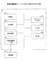
図1は、各実施例における情報設定システムの一例を示す図である。図1に示すように、情報設定システムは、ネットワークを介して画像形成装置10、20、30、情報処理装置(サーバ)40が接続されている。各画像形成装置は、情報処理装置40とデータ通信をすることができる。画像形成装置は、例えばMFP(Multifunction Peripheral)やプリンタである。
[Example]
<System>
FIG. 1 is a diagram illustrating an example of an information setting system in each embodiment. As shown in FIG. 1, in the information setting system,
画像形成装置10は、例えば、スキャン機能、コピー機能、プリンタ機能、ファクシミリ機能などを一つの筐体に搭載したものである。画像形成装置10は、情報処理装置40に対し、各機能(アプリケーション)の設定情報の取得要求を送信する。この設定情報は、プリファレンス情報ともいう。画像形成装置10は、取得したプリファレンス情報を用いて機器設定を行う。なお、画像形成装置20、30は、画像形成装置10と同様であるため、以下では画像形成装置10を用いて説明する。
The
情報処理装置40は、ネットワークを介して接続される各画像形成装置で共通して設定されるプリファレンス情報を保持する。情報処理装置40は、各画像形成装置からプリファレンス情報の取得要求を受信した場合は、プリファレンス情報を各画像形成装置に送信する。
The
つまり、本実施例では、共通のプリファレンス情報を複数の画像形成装置に設定する際、PULL型の設定方法を提供する。 In other words, this embodiment provides a PULL type setting method when setting common preference information to a plurality of image forming apparatuses.
<ハードウェア>
図2は、図1の画像形成装置10に係るハードウェアの一例を示すブロック図である。画像形成装置10のハードウェアとしては、コントローラ101と、オペレーションパネル102と、ファクシミリコントロールユニット(FCU)103と、プロッタ104、スキャナ105及びその他ハードウェア106で構成されるエンジン部107を含む。
<Hardware>
FIG. 2 is a block diagram illustrating an example of hardware according to the
コントローラ101は、CPU111、ASIC112、NB121、SB122、MEM−P131、MEM−C132、HDD(ハードディスクドライブ)133、NIC(ネットワークインタフェースコントローラ)141、USBデバイス142、IEEE1394デバイス143、セントロニクスデバイス144を含む。
The
CPU111は、種々の情報処理用のICである。ASIC112は、種々の画像処理用のICである。NB121は、コントローラ101のノースブリッジである。SB122は、コントローラ101のサウスブリッジである。MEM−P131は、画像形成装置10のシステムメモリである。MEM−C132は、画像形成装置10のローカルメモリである。HDD133は、画像形成装置10のストレージである。
The
NIC141は、MACアドレスによるネットワーク通信用のコントローラである。USBデバイス142は、USB規格の接続端子を提供するためのデバイスである。IEEE1394デバイス143は、IEEE1394規格の接続端子を提供するためのデバイスである。セントロニクスデバイス144は、セントロニクス仕様の接続端子を提供するためのデバイスである。
The
オペレーションパネル102は、オペレータが画像形成装置10に入力を行うためのハードウェア(操作部)であると共に、オペレータが画像形成装置10から出力を得るためのハードウェア(表示部)である。
The
FCU103は、受信したファックスデータを格納し、通常G3規格に従ってファックスデータの送受信を行う。FCU103は、オプションとしてさらにG3規格とG4規格とを搭載してもよい。プロッタ104は、印刷処理を行う。スキャナ105は、原稿を読み取り、文書データを生成する。
The
図3は、実施例における情報処理装置40のハードウェアの一例を示すブロック図である。図3に示すように、情報処理装置40は、制御部401、主記憶部402、補助記憶部403、外部記憶装置I/F部404、ネットワークI/F部406、入力部407、表示部408を含む。これら各構成は、バスを介して相互にデータ送受信可能に接続されている。
FIG. 3 is a block diagram illustrating an example of hardware of the
制御部401は、コンピュータの中で、各装置の制御やデータの演算、加工を行うCPUである。また、制御部401は、主記憶部402に記憶されたプログラムを実行する演算装置であり、入力装置や記憶装置からデータを受け取り、演算、加工した上で、出力装置や記憶装置に出力する。
The
主記憶部402は、ROM(Read Only Memory)やRAM(Random Access Memory)などであり、制御部401が実行する基本ソフトウェアであるOSやアプリケーションソフトウェアなどのプログラムやデータを記憶又は一時保存する記憶装置である。
The
補助記憶部403は、HDD(Hard Disk Drive)などであり、アプリケーションソフトウェアなどに関連するデータを記憶する記憶装置である。
The
外部記憶装置I/F部404は、USB(Universal Serial Bus)などのデータ伝送路を介して接続された記憶媒体405(例えば、フラッシュメモリ、SDカードなど)と情報処理装置40とのインタフェースである。
The external storage device I /
また、記憶媒体405に、所定のプログラムを格納し、この記憶媒体405に格納されたプログラムは外部記憶装置I/F部404を介して情報処理装置40にインストールされ、インストールされた所定のプログラムは情報処理装置40により実行可能となる。
Further, a predetermined program is stored in the
ネットワークI/F部406は、有線及び/又は無線回線などのデータ伝送路により構築されたLAN(Local Area Network)、WAN(Wide Area Network)などのネットワークを介して接続された通信機能を有する周辺機器と情報処理装置40とのインタフェースである。
The network I /
入力部407は、カーソルキー、数字入力及び各種機能キー等を備えたキーボード、表示部408の表示画面上でキーの選択等を行うためのマウスやスライスパット等を有する。また、入力部407は、ユーザが制御部401に操作指示を与えたり、データを入力したりするためのユーザインタフェースである。
The
表示部408は、CRTやLCD等により構成され、制御部401から入力される表示データに応じた表示が行われる。なお、情報処理装置40は、サーバであるため、入力部407と表示部408とは必ずしも備えなくてもよい。
The
<構成>
・画像形成装置10
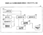
図4は、実施例における画像形成装置10の構成の一例を示すブロック図である。図4に示すように、画像形成装置10は、更新制御手段501、通信制御手段502、設定情報制御手段503、情報記憶手段504、操作手段505、電源制御手段506、メール制御手段507、機器状態管理手段508、ジョブ状態監視手段509を含む。
<Configuration>
FIG. 4 is a block diagram illustrating an example of the configuration of the
操作手段505は、例えばオペレーションパネル202により実現され、情報記憶手段504は、例えばHDD133により実現され、通信制御手段502は、例えばNIC141により実現され、その他の構成は、例えばCPU111により実現されうる。なお、情報記憶手段504以外の各構成は、モジュールとして実装されうる。
The
更新制御手段501は、所定のトリガを検知してプリファレンス情報の設定、更新を制御する。所定のトリガとは、管理者による操作や、電源ON時(起動時)、定期的、サーバ側からのアップデート通知の受信、機器異常発生などが考えられる。
The
更新制御手段501は、未処理のジョブを優先するか、プリファレンス情報の更新を優先するかの何れかを示す設定値を保持する。この設定は、操作手段505により設定可能である。
The
更新制御手段501は、この設定に基づいて、情報処理装置40から取得したプリファレンス情報の更新タイミングを決定する。この更新タイミングの詳細については後述する。
Based on this setting, the
通信制御手段502は、ネットワークで接続された外部機器との通信を制御する。通信制御手段502は、例えば更新制御手段501からの指示によりプリファレンス情報の取得要求を情報処理装置40に送信したり、情報処理装置40からプリファレンス情報を受信したりする。通信制御手段502は、プリファレンス情報の取得要求を送信する前に認証用の機器IDや認証情報(ユーザアカウント、パスワード)を送信してもよい。設定情報制御手段503は、プリファレンス情報の機器への設定を制御する。情報記憶手段504は、機器に設定されるプリファレンス情報などを記憶する。
A
操作手段505は、ユーザからの操作の受け付けと、ユーザへの画面表示を行う。操作手段505は、例えば管理者がプリファレンス情報の更新を指示したときに、その旨を更新制御手段501に通知する。操作手段505は、ジョブを優先するか、プリファレンス情報の更新を優先するかのどちらかを選択する画面を表示する。
The
図5は、モード選択画面の一例を示す図である。図5に示す例では、更新優先モード、ジョブ優先モードのどちらかが選択できるようになっている。ここで、操作手段505は、管理者により選択されたモードを検知し、選択されたモードを更新制御手段501に通知する。
FIG. 5 is a diagram illustrating an example of the mode selection screen. In the example shown in FIG. 5, either the update priority mode or the job priority mode can be selected. Here, the
図4に戻り、電源制御手段506は、電源のON、OFFを制御する。メール制御手段507は、ユーザへのメール送信を制御する。メール制御手段507は、例えば登録されている送信先に対し、プリファレンス情報の設定失敗や失敗の原因を記載したメールを送信する。
Returning to FIG. 4, the
機器状態管理手段508は、機器の状態を管理し、他の構成に異常状態などの通知を行う。ジョブ状態監視手段509は、機器内にジョブがあるかを監視し、ジョブがある場合はそのジョブの状態を他の構成に通知する。ジョブの状態は、実行中、未処理、一時停止などがある。
The device
画像形成装置10は、以上の構成を有することで、所定のトリガによって、情報処理装置40にプリファレンス情報の取得要求を行い、情報処理装置40から取得したプリファレンス情報を設定、更新することができる。また、画像形成装置10は、プリファレンス情報を取得した際に、未処理のジョブがある場合、ジョブの前に更新するのか、未処理のジョブを処理してから更新するのかを決めておくことで、予期しない設定値によるジョブの処理を防止することができる。画像形成装置20、30は、画像形成装置10と同様の構成を有する。
With the above-described configuration, the
・情報処理装置40
図6は、情報処理装置40の構成の一例を示すブロック図である。図6に示す例では、情報処理装置40は、通信制御手段601、認証制御手段602、情報管理手段603、情報記憶手段604を含む。
FIG. 6 is a block diagram illustrating an example of the configuration of the
通信制御手段601は、例えばネットワークI/F部406により実現され、情報記憶手段604は、例えば補助記憶部403により実現され、その他の構成は、例えば制御部401及びワークメモリとしての主記憶部402により実現されうる。なお、情報記憶手段604以外の各構成は、モジュールとして実装されうる。
The
通信制御手段601は、ネットワークで接続された外部装置との通信の制御を行う。通信制御手段601は、例えば、画像形成装置10からプリファレンス情報の取得要求や認証情報を受信する。また、通信制御手段601は、画像形成装置10に対し、プリファレンス情報を送信する。
The
認証制御手段602は、通信制御手段601が認証情報を取得した場合、この認証情報を用いて認証処理を行う。例えば、認証処理は、取得した機器IDの照合をしたり、ユーザアカウント、パスワードの照合をしたりする。通信制御手段601は、認証結果を画像形成装置10に送信する。
When the
情報管理手段603は、通信制御手段601が、プリファレンス情報の取得要求を受信した場合、情報記憶手段604からプリファレンス情報の読み出しを行う。
When the
情報記憶手段604は、ネットワークに接続される各画像形成装置で共通して設定されるプリファレンス情報を記憶する。
The
図7は、プリファレンス情報の一例を示す図である。図7に示す例では、全ての設定項目が一つのファイルで管理されている。また、各設定項目に対し、設定値の設定例を示している。このプリファレンス情報の設定値が各画像形成装置に設定されることになる。 FIG. 7 is a diagram illustrating an example of preference information. In the example shown in FIG. 7, all setting items are managed by one file. In addition, setting values are set for each setting item. The setting value of the preference information is set in each image forming apparatus.
なお、情報処理装置40は、プリファレンス情報が更新された場合には、ネットワークに接続される各画像形成装置に対し、通信制御手段601を用いてアップデート通知を送信する。
When the preference information is updated, the
情報処理装置40は、以上の構成を有することで、共通のプリファレンス情報を複数の画像形成装置に設定を行いたい場合でも、各画像形成装置によってプリファレンス情報のダウンロードを行う時間が異なる場合があるので、通信路に多大な負荷をかけることを軽減することができる。また、管理者によるプリファレンス情報の管理が容易になる。
Since the
<動作>
次に、実施例における情報設定システムの動作について説明する。まず、プリファレンス情報の設定処理について説明する。
<Operation>
Next, the operation of the information setting system in the embodiment will be described. First, preference information setting processing will be described.
(プリファレンス情報の設定処理)
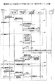
図8は、実施例におけるプリファレンス情報の設定処理の一例を示すシーケンス図である。図8に示すステップS101で、更新制御手段501は、所定のトリガに基づき、プリファレンス情報のインポート要求を検知する。
(Preference information setting process)
FIG. 8 is a sequence diagram illustrating an example of preference information setting processing in the embodiment. In step S101 shown in FIG. 8, the
ステップS102で、更新制御手段501は、インポート要求があると判断すると、通信制御手段502を介して、情報処理装置40に対し、プリファレンス情報のダウンロード要求を送信する。
In step S <b> 102, when the
ステップS103で、情報処理装置40は、画像形成装置10からプリファレンス情報のダウンロード要求を受信すると、プリファレンス情報を読み出して、画像形成装置10に送信する。
In step S <b> 103, when the
ステップS104で、更新制御手段501は、設定情報制御手段503に対して、ダウンロードしたプリファレンス情報の設定要求を行う。設定情報制御手段503は、情報記憶手段504に記憶される設定情報(プリファレンス情報)を、ダウンロードしたプリファレンス情報に設定、更新する。
In step S104, the
これにより、ネットワーク上の各画像形成装置が図8に示す処理を行うことで、通信路に対して一度に負荷をかけずに、各画像形成装置で、共通のプリファレンス情報を適切に設定することができる。 As a result, each image forming apparatus on the network performs the processing shown in FIG. 8 so that common preference information is appropriately set in each image forming apparatus without applying a load to the communication path at once. be able to.
(モードに基づくプリファレンス情報の設定処理)
図9は、実施例におけるジョブ優先モード時のプリファレンス情報の設定処理の一例を示すシーケンス図である。図9に示す例では、画像形成装置10には、ジョブ優先モードが設定されているとする。図9に示すステップS201で、更新制御手段501は、所定のトリガに基づき、インポート要求を検知する。
(Preference information setting process based on mode)
FIG. 9 is a sequence diagram illustrating an example of preference information setting processing in the job priority mode according to the embodiment. In the example illustrated in FIG. 9, it is assumed that the job priority mode is set in the
ステップS202で、更新制御手段501は、機器内にあるジョブの状態を確認するため、ジョブ状態監視手段509にジョブ状態取得要求を出力する。
In step S202, the
ステップS203で、ジョブ状態監視手段509は、機器内にあるジョブの状態を更新制御手段501に出力する。
In step S203, the job
更新制御手段501は、ジョブ優先モードが設定されているので、ステップS202、S203を全てのジョブが終了するまで繰り返し行う。全てのジョブが終了した場合には、更新制御手段501は、更新処理を開始する。更新処理は、図8に示すステップS102〜S104の処理である。
Since the job priority mode is set, the
これにより、機器内にあるジョブが全て終了してからプリファレンス情報の更新を行うため、画像形成装置の利用に支障が出ないという利点がある。なお、「機器内にあるジョブ」とは、実行待機中のジョブ、実行中のジョブ、一時停止中のジョブである。また、「ジョブ」とは、画像形成装置における画像形成に関する処理を表し、画像データの印刷、配信、変換などの処理である。 As a result, the preference information is updated after all the jobs in the device are completed, and there is an advantage that the use of the image forming apparatus is not hindered. The “job in the device” is a job waiting for execution, a job being executed, or a job being paused. A “job” represents processing related to image formation in the image forming apparatus, and is processing such as printing, distribution, and conversion of image data.
図10は、実施例における更新優先モード時のプリファレンス情報の設定処理の一例を示すシーケンス図である。図10に示す例では、画像形成装置10には、更新優先モードが設定されているとする。図10に示すステップS301で、更新制御手段501は、所定のトリガに基づき、インポート要求を検知する。
FIG. 10 is a sequence diagram illustrating an example of preference information setting processing in the update priority mode in the embodiment. In the example illustrated in FIG. 10, it is assumed that the update priority mode is set in the
ステップS302で、更新制御手段501は、機器内にあるジョブの状態を確認するため、ジョブ状態監視手段509にジョブ状態取得要求を出力する。
In step S302, the
ステップS303で、ジョブ状態監視手段509は、機器内にあるジョブの状態を更新制御手段501に出力する。
In step S <b> 303, the job
ここで、更新制御手段501は、更新優先モードが設定されているので、現在実行中のジョブが終了した後に、プリファレンス情報の更新処理を行うため、以下の処理を実行する。
Here, since the update priority mode is set, the
ステップS304で、更新制御手段501は、未処理のジョブを有する各アプリケーション(以下、アプリともいう)に対し、ジョブを中断するよう制御する。ここでいうジョブの中断とは、例えばジョブを一時停止することである。
In step S304, the
ステップS305で、各アプリは、中断が完了した場合、更新制御手段501に中断完了を通知する。これは、処理順が先頭の「待機中」のジョブが、実行中のジョブが終了した後、プリファレンス情報の更新中に、このジョブが実行されないようにするためである。
In step S305, each application notifies the
次に、更新制御手段501は、機器内にジョブがある各アプリから中断完了の通知を取得すると、プリファレンス情報の更新処理を開始する。更新処理は、図8に示すステップS102〜S104の処理である。
Next, the
ステップS306で、更新制御手段501は、更新処理が完了した場合、各アプリに対し、ジョブの再開操作を行う。更新制御手段501は、各アプリに対し、「一時停止」状態から「待機中」状態に戻すよう制御する。
In step S306, when the update process is completed, the
これにより、プリファレンス情報の更新処理を迅速に行うため、更新したプリファレンス情報の設定値によってジョブを実行することができる。 Accordingly, in order to quickly update the preference information, the job can be executed with the updated setting value of the preference information.
図11は、実施例における確認によるプリファレンス情報の設定処理(その1)の一例を示すシーケンス図である。図11に示す例では、管理者A1がプリファレンス情報の更新を操作した際、機器内に待機中のジョブがある場合には、更新する、更新しない、ジョブの終了後に更新する、のいずれかを管理者A1に選択させる。 FIG. 11 is a sequence diagram illustrating an example of preference information setting processing (part 1) based on confirmation in the embodiment. In the example shown in FIG. 11, when the administrator A1 operates the update of the preference information, if there is a waiting job in the device, either update, do not update, or update after the end of the job. Is selected by the administrator A1.
ステップS401で、管理者A1は、プリファレンス情報更新の操作を行う。ステップS402で、操作手段505は、プリファレンス情報更新の操作を検知すると、更新制御手段501に対し、更新要求を通知する。
In step S401, the administrator A1 performs a preference information update operation. In step S402, when the
ステップS403で、更新制御手段501は、ジョブ状態監視手段509に対し、ジョブ状態の取得要求を出力する。
In step S403, the
ステップS404で、ジョブ状態監視手段509は、機器内にあるジョブの状態を更新制御手段501に出力する。
In step S <b> 404, the job
ステップS405で、更新制御手段501は、更新開始の確認画面を表示するよう操作手段505に通知する。
In step S405, the
ステップS406で、操作手段505は、更新開始の確認画面を表示し、管理者A1にこの後の処理を選択させる。
In step S406, the
図12は、確認画面(その1)の一例を示す図である。図12に示す例では、更新要求がされた場合、機器内にジョブがあれば、実行中のジョブの処理後に更新を行うか(図12に示す「はい」)、更新を中止するか(図12に示す「いいえ」)、全てのジョブの処理が終了してから更新するか(図12に示す「ジョブ終了後に開始」)を管理者A1に選択させる。 FIG. 12 is a diagram illustrating an example of the confirmation screen (part 1). In the example shown in FIG. 12, when an update request is made, if there is a job in the device, the update is performed after the processing of the job being executed (“Yes” shown in FIG. 12) or the update is canceled (FIG. 12). Or “No” shown in FIG. 12), or the administrator A1 selects whether to update after the processing of all jobs is finished (“start after job” shown in FIG. 12).
図12に示す「はい」ボタンが押下された場合、ステップS11の処理が行われ、図12に示す「いいえ」ボタンが押下された場合、ステップS12の処理が行われ、図12に示す「ジョブ終了後に開始」ボタンが押下された場合、ステップS13の処理が行われる。 When the “Yes” button shown in FIG. 12 is pressed, the process of step S11 is performed. When the “No” button shown in FIG. 12 is pressed, the process of step S12 is performed, and the “job” shown in FIG. When the “start after completion” button is pressed, the process of step S13 is performed.
・「はい」ボタン押下
ステップS11では、ステップS407〜S411の処理が実行される。ステップS407で、管理者A1は、図12に示す「はい」ボタンを押下する。
-"Yes" button press In step S11, the process of step S407-S411 is performed. In step S407, the administrator A1 presses the “Yes” button shown in FIG.
ステップS408で、操作手段505は、「はい」ボタンの押下を検知すると、更新開始であると判断して、更新制御手段501に更新開始を通知する。
In step S <b> 408, when the
ステップS409〜S411は、図10に示すステップS304〜S306の処理と同様であるため、その説明を省略する。 Steps S409 to S411 are the same as the processes of steps S304 to S306 shown in FIG.
・「いいえ」ボタン押下
ステップS12では、ステップS412〜S415の処理が実行される。ステップS412で、管理者A1は、図12に示す「いいえ」ボタンを押下する。
-"No" button press In step S12, the process of step S412-S415 is performed. In step S412, the administrator A1 presses a “NO” button shown in FIG.
ステップS413で、操作手段505は、「いいえ」ボタンの押下を検知すると、更新終了であると判断して、更新制御手段501に更新終了を通知する。
In step S <b> 413, when the
ステップS414で、更新制御手段501は、操作手段505から更新終了を通知されると、操作手段505に対し、更新終了通知画面の表示要求を行う。
In step S <b> 414, when the
ステップS415で、操作手段505は、更新終了通知画面(不図示)を表示し、管理者A1に更新終了を知らせる。
In step S415, the
・「ジョブ終了後に開始」ボタン押下
ステップS13では、ステップS416〜S419、更新処理が実行される。ステップS416で、管理者A1は、図12に示す「ジョブ終了後に開始」ボタンを押下する。
“Start after Job End” Button Pressed In step S13, steps S416 to S419 and update processing are executed. In step S416, the administrator A1 presses a “start after job” button shown in FIG.
ステップS417で、操作手段505は、「ジョブ終了後に開始」ボタンの押下を検知すると、更新待機であると判断して、更新制御手段501に更新待機を通知する。
In step S417, when the
ステップS418、S419、更新処理は、図9に示すステップS202、S203、図8に示すステップS102〜S104の処理と同様であるため、その説明を省略する。 Steps S418 and S419 and the update process are the same as the processes of steps S202 and S203 shown in FIG. 9 and steps S102 to S104 shown in FIG.
これにより、プリファレンス情報の更新を要求した際に機器内にジョブがある場合、その都度管理者に更新処理をどうするかを選択させることができる。 Thereby, when there is a job in the device when the update of the preference information is requested, the administrator can select how to perform the update process each time.
図13は、実施例における確認によるプリファレンス情報の設定処理(その2)の一例を示すシーケンス図である。図13に示す例では、管理者A1がプリファレンス情報の更新を操作した際、機器内に待機中のジョブがある場合には、ジョブの内容を表示して、更新する、更新しない、更新を待機する、のいずれかを管理者A1に選択させる。 FIG. 13 is a sequence diagram illustrating an example of preference information setting processing (part 2) by confirmation in the embodiment. In the example shown in FIG. 13, when the administrator A1 operates the update of the preference information, if there is a waiting job in the device, the contents of the job are displayed and updated, not updated, or updated. The administrator A1 is made to select any one of waiting.
ステップS501で、管理者A1は、プリファレンス情報更新の操作を行う。ステップS502で、操作手段505は、プリファレンス情報更新の操作を検知すると、更新制御手段501に対し、更新要求を通知する。
In step S501, the administrator A1 performs a preference information update operation. In step S502, when the
ステップS503で、更新制御手段501は、ジョブ状態監視手段509に対し、ジョブ状態などの取得要求を出力する。
In step S503, the
ステップS504で、ジョブ状態監視手段509は、機器内にあるジョブの状態、ジョブ名、アプリ名などを更新制御手段501に出力する。
In step S504, the job
ステップS505で、更新制御手段501は、更新開始の確認画面を表示するよう操作手段505に通知する。
In step S505, the
ステップS506で、操作手段505は、更新開始の確認画面を表示し、管理者A1にこの後の処理を選択させる。
In step S506, the
図14は、確認画面(その2)の一例を示す図である。図14に示す例では、待機中のジョブの内容が表示される。ジョブの内容は、例えば、ジョブID、ファイル名、ジョブ状態、実行するアプリなどである。 FIG. 14 is a diagram illustrating an example of a confirmation screen (part 2). In the example illustrated in FIG. 14, the contents of a job that is on standby are displayed. The contents of the job are, for example, a job ID, a file name, a job status, an application to be executed, and the like.
これにより、更新要求がされた場合、機器内にジョブがあれば、待機中のジョブの内容を表示し、未処理のジョブの前に更新を行うか(図14に示す「はい」)、更新を中止するか(図14に示す「いいえ」)、全てのジョブが終了してから更新するか(図14に示す「待機」)を管理者A1に選択させることができる。 As a result, when an update request is made, if there is a job in the device, the contents of the waiting job are displayed and whether the update is performed before the unprocessed job ("Yes" shown in FIG. 14) or update. The administrator A1 can select whether to cancel ("No" shown in FIG. 14) or update after all jobs are finished ("Standby" shown in FIG. 14).
図14に示す「はい」ボタンが押下された場合、ステップS21の処理が行われ、図14に示す「いいえ」ボタンが押下された場合、ステップS23の処理が行われ、図14に示す「待機」ボタンが押下された場合、ステップS22の処理が行われる。 When the “yes” button shown in FIG. 14 is pressed, the process of step S21 is performed. When the “no” button shown in FIG. 14 is pressed, the process of step S23 is performed, and the “standby” shown in FIG. "Button is pressed, the process of step S22 is performed.
・「はい」ボタン押下
ステップS21では、ステップS507〜S513の処理が実行される。ステップS507で、管理者A1は、図14に示す「はい」ボタンを押下する。
-"Yes" button press In step S21, the process of step S507-S513 is performed. In step S507, the administrator A1 presses the “Yes” button shown in FIG.
ステップS508で、操作手段505は、「はい」ボタンの押下を検知すると、更新開始であると判断して、更新制御手段501に更新優先モードの更新要求を通知する。
In step S <b> 508, when the
ステップS509で、更新制御手段501は、ジョブ状態監視手段509に対し、ジョブ状態の取得要求を行う。
In step S509, the
ステップS510で、ジョブ状態監視手段509は、機器内のジョブの状態を更新制御手段501に出力する。
In step S <b> 510, the job
ステップS511〜S513は、図10に示すステップS304〜S306の処理と同様であるため、その説明を省略する。 Steps S511 to S513 are the same as the processes of steps S304 to S306 shown in FIG.
・「待機」ボタン押下
ステップS22では、ステップS515〜S518、更新処理が実行される。ステップS515で、管理者A1は、図14に示す「待機」ボタンを押下する。
-"Standby" button is pressed In steps S22, steps S515 to S518, update processing is executed. In step S515, the administrator A1 presses a “standby” button shown in FIG.
ステップS516で、操作手段505は、「待機」ボタンの押下を検知すると、ジョブ優先モードの更新要求であると判断して、更新制御手段501にジョブ優先モードの更新要求を通知する。
In step S516, when the
ステップS517、S518、更新処理は、図9に示すステップS202、S203、図8に示すステップS102〜S104の処理と同様であるため、その説明を省略する。 Steps S517 and S518 and the update process are the same as the processes in steps S202 and S203 shown in FIG. 9 and steps S102 to S104 shown in FIG.
・「いいえ」ボタン押下
ステップS23では、ステップS519〜S523の処理が実行される。ステップS519で、管理者A1は、図14に示す「いいえ」ボタンを押下する。
-"No" button press In step S23, the process of step S519-S523 is performed. In step S519, the administrator A1 presses a “No” button shown in FIG.
ステップS520で、操作手段505は、「いいえ」ボタンの押下を検知すると、更新中止であると判断して、更新制御手段501に更新中止を通知する。
In step S520, when the
ステップS521、S522で、更新制御手段501は、操作手段505から更新中止を通知されると、操作手段505に対し、更新中止通知画面(不図示)の表示要求を行う。
In steps S <b> 521 and S <b> 522, when the
ステップS523で、操作手段505は、更新中止通知画面を表示し、管理者A1に更新中止を知らせる。
In step S523, the
これにより、プリファレンス情報の更新を要求した際に機器内にジョブがある場合、待機中のジョブの内容を表示することで、管理者はそのジョブ内容に応じて更新処理をどうするかを選択させることができる。 As a result, when there is a job in the device when the update of the preference information is requested, the content of the waiting job is displayed so that the administrator can select how to perform the update process according to the job content. be able to.
図15は、実施例におけるジョブ毎に行うプリファレンス情報の設定処理の一例を示すシーケンス図である。図15に示す例では、ジョブ毎にジョブ優先モード、更新優先モードが設定されている。これらの設定は、情報記憶手段504に記憶され、更新制御手段501が適宜参照するようにすればよい。例えば、コピージョブに対しては、ジョブ優先モード、メール送信ジョブについては更新優先モードというように設定されているとする。
FIG. 15 is a sequence diagram illustrating an example of preference information setting processing performed for each job in the embodiment. In the example shown in FIG. 15, a job priority mode and an update priority mode are set for each job. These settings may be stored in the
図15に示すステップS601で、管理者A1は、プリファレンス情報更新の操作を行う。ステップS602で、操作手段505は、プリファレンス情報更新の操作を検知すると、更新制御手段501に対し、更新要求を通知する。
In step S601 shown in FIG. 15, the administrator A1 performs an operation for updating preference information. In step S602, when the
ステップS603で、更新制御手段501は、ジョブ状態監視手段509に対し、ジョブ状態などの取得要求を出力する。
In step S <b> 603, the
ステップS604で、ジョブ状態監視手段509は、機器内にあるジョブの状態、ジョブ名、アプリ名などを更新制御手段501に出力する。
In step S604, the job
ステップS605で、更新制御手段501は、ジョブ優先モードが設定されたジョブが、待機しているジョブにあるかを確認する。待機中のジョブにジョブ優先モードが設定されていなかった場合、ステップS31に進み、待機中のジョブにジョブ優先モードが設定されていた場合、ステップS32に進む。
In step S605, the
・待機中のジョブにジョブ優先モードが設定されていなかった場合
ステップS31では、ステップS606〜S608(更新処理含む)の処理が実行される。ステップS606〜S608の処理は、図10に示すステップS304〜S306の処理と同様であるため、その説明を省略する。つまり、更新優先モード時の設定処理が行われる。
When the job priority mode is not set for the waiting job In steps S31, the processing of steps S606 to S608 (including update processing) is executed. The processing in steps S606 to S608 is the same as the processing in steps S304 to S306 shown in FIG. That is, setting processing in the update priority mode is performed.
・待機中のジョブにジョブ優先モードが設定されていた場合
ステップS32では、ステップS609、S610、更新処理が実行される。ステップS609、S610、更新処理は、図9に示すステップS202、S203、図8に示すステップS102〜S104の処理と同様であるため、その説明を省略する。つまり、ジョブ優先モード時の設定処理が行われる。
When the job priority mode is set for the waiting job In steps S32, steps S609 and S610, and update processing are executed. Steps S609 and S610 and the update process are the same as the processes of steps S202 and S203 shown in FIG. 9 and steps S102 to S104 shown in FIG. That is, setting processing in the job priority mode is performed.
これにより、ジョブ毎にジョブ優先モードか更新優先モードかを設定しておくことで、待機しているジョブに応じて適応的にモードを切り替えてプリファレンス情報の更新処理を行うことができる。 Thus, by setting the job priority mode or the update priority mode for each job, it is possible to adaptively switch the mode according to the waiting job and perform the update process of the preference information.
また、待機中のジョブが複数ある場合、ジョブ優先モードが設定されているジョブが先に処理されるようジョブのスケジューリングを行ってもよい。この場合、ジョブ優先モードのジョブが全て終了した後に、更新処理が行われる。次に、更新処理後に、更新優先モードが設定されていたジョブが順に処理されることになる。 Further, when there are a plurality of jobs waiting, job scheduling may be performed so that a job for which the job priority mode is set is processed first. In this case, the update process is performed after all jobs in the job priority mode are completed. Next, after the update process, jobs for which the update priority mode has been set are sequentially processed.
(設定エラー処理)
図16は、実施例における設定エラー処理(その1)の一例を示すシーケンス図である。ここで、設定エラーとは、プリファレンス情報の取得、設定に関するエラーのことをいう。図16に示す設定エラーは、プリファレンス情報の設定失敗である。
(Setting error processing)
FIG. 16 is a sequence diagram illustrating an example of setting error processing (part 1) in the embodiment. Here, the setting error means an error related to acquisition and setting of preference information. The setting error shown in FIG. 16 is a preference information setting failure.
図16に示すステップS701で、管理者A1は、プリファレンス情報更新の操作を行う。ステップS702で、操作手段505は、プリファレンス情報更新の操作を検知すると、更新制御手段501に対し、更新要求を通知する。ここで、更新制御手段501は、更新優先モードが設定されているか、ジョブ優先モードが設定されているかを判定する。更新優先モードが設定されている場合、ステップS41の処理に進み、ジョブ優先モードが設定されている場合、ステップS42の処理に進む。
In step S701 shown in FIG. 16, the administrator A1 performs an operation for updating preference information. In step S <b> 702, when the
更新優先モードの処理(S41)では、ステップS703〜S706の処理が実行される。ステップS703〜S706の処理は、図10に示すS302〜S305の処理と同様であるため、その説明を省略する。 In the update priority mode process (S41), the processes of steps S703 to S706 are executed. The processing of steps S703 to S706 is the same as the processing of S302 to S305 shown in FIG.
ジョブ優先モードの処理(S42)では、ステップS707、S708の処理が実行される。ステップS707、S708の処理は、図9に示すステップS202、S203の処理と同様であるため、その説明を省略する。 In the job priority mode process (S42), the processes of steps S707 and S708 are executed. The processes in steps S707 and S708 are the same as the processes in steps S202 and S203 shown in FIG.
ステップS709で、更新制御手段501は、インポート要求を検知する。ここで、ステップS710〜712の処理は、図8に示すステップS102〜S104の処理と同様であるため、その説明を省略する。
In step S709, the
ステップS713で、更新制御手段501は、設定失敗を検知する。設定失敗は、情報記憶手段504にプリファレンス情報を反映する場合に失敗することをいう。例えば、情報記憶手段504の障害や、プリファレンス情報に異常値が設定されていた場合が、設定失敗になる。
In step S713, the
ステップS714で、更新制御手段501は、操作手段505に対し、設定失敗通知画面を表示するよう制御する。
In step S714, the
ステップS715で、操作手段505は、更新制御手段501から設定失敗通知画面を表示するよう指示を受けると、設定失敗通知画面を表示する。
In step S715, when the
図17は、実施例における失敗通知画面(その1)の一例を示す図である。図17に示す失敗通知画面では、設定失敗であることを表示する。図17に示す失敗通知画面には、「リトライ」ボタンと「中止」ボタンが表示される。 FIG. 17 is a diagram illustrating an example of the failure notification screen (part 1) in the embodiment. The failure notification screen shown in FIG. 17 displays that the setting has failed. On the failure notification screen shown in FIG. 17, a “retry” button and a “cancel” button are displayed.
図17に示す「リトライ」ボタンが押下されると、ステップS43の処理が実行され、図17に示す「中止ボタン」が押下されると、ステップS44の処理が実行される。 When the “Retry” button shown in FIG. 17 is pressed, the process of Step S43 is executed, and when the “Cancel button” shown in FIG. 17 is pressed, the process of Step S44 is executed.
ステップS43の処理は、ステップS712の処理からやり直す処理である。ステップS44の処理では、ステップS716〜S720の処理が実行される。 The process in step S43 is a process that starts over from the process in step S712. In the process of step S44, the processes of steps S716 to S720 are executed.
ステップS716で、管理者A1は、図17に示す「中止」ボタンを押下する。ステップS717で、操作手段505は、「中止」ボタンの押下を検知すると、更新中止であると判断して、更新制御手段501に更新中止を通知する。
In step S716, the administrator A1 presses the “CANCEL” button shown in FIG. In step S717, when the
ステップS718、S719で、更新制御手段501は、操作手段505から更新中止を通知されると、操作手段505に対し、更新中止通知画面(不図示)の表示要求を行う。
In Steps S718 and S719, when the
ステップS720で、操作手段505は、更新中止通知画面を表示し、管理者A1に更新中止を知らせる。
In step S720, the
ステップS721で、更新制御手段501は、更新優先モードであった場合、各アプリに対し、ジョブの再開操作を行う。
In step S721, if the
これにより、画像形成装置10は、設定失敗の場合に管理者にその後の処理を選択させることができる。なお、ステップS41、S42の処理は、ステップS711の処理の後に行ってもよい。
As a result, the
図18は、実施例における設定エラー処理(その2)の一例を示すシーケンス図である。図18に示す設定エラーは、プリファレンス情報の更新失敗である。更新失敗とは、情報処理装置40からプリファレンス情報をダウンロードする際の失敗をいう。
FIG. 18 is a sequence diagram illustrating an example of setting error processing (part 2) in the embodiment. The setting error shown in FIG. 18 is a failure to update preference information. An update failure refers to a failure when downloading preference information from the
図18に示すステップS801で、管理者A1は、プリファレンス情報更新の操作を行う。ステップS802で、操作手段505は、プリファレンス情報更新の操作を検知すると、更新制御手段501に対し、更新要求を通知する。ここで、更新制御手段501は、更新優先モードが設定されているか、ジョブ優先モードが設定されているかを判定する。更新優先モードが設定されている場合、ステップS51の処理に進み、ジョブ優先モードが設定されている場合、ステップS52の処理に進む。
In step S801 illustrated in FIG. 18, the administrator A1 performs an operation for updating preference information. In step S802, when the
更新優先モードの処理S51(ステップS803〜S806)は、図16に示すステップS41の処理と同様であり、ジョブ優先モードの処理S52(ステップS807、S808)は、図16に示すステップS42の処理と同様であるため、その説明を省略する。ステップS51又はS52の処理の後に、更新処理を開始する。 The update priority mode process S51 (steps S803 to S806) is the same as the process of step S41 shown in FIG. 16, and the job priority mode process S52 (steps S807 and S808) is the same as the process of step S42 shown in FIG. Since it is the same, the description is omitted. The update process is started after the process of step S51 or S52.
本来ならば、更新処理は、図8に示すステップS102〜S104の処理が行われるが、この場合、ステップS102、S103の何れかでエラーが生じ、プリファレンス情報のダウンロードに失敗したとする。 Originally, the update process is performed in steps S102 to S104 shown in FIG. 8. In this case, it is assumed that an error occurs in any of steps S102 and S103 and the download of the preference information has failed.
ステップS809で、更新制御手段501は、更新失敗及び更新失敗の理由が通知される。更新失敗及びその理由は、失敗原因によって通知元が異なるため、明記していない。更新失敗の原因としては、ネットワーク障害や、メモリへの一時保存時の書き込みエラーなどが考えられる。
In step S809, the
ステップS810で、更新制御手段501は、操作手段505に対し、更新失敗通知画面を表示するよう制御する。
In step S810, the
ステップS811で、操作手段505は、更新制御手段501から更新失敗通知画面を表示するよう指示を受けると、更新失敗通知画面を表示する。
In step S811, when the
図19は、実施例における失敗通知画面(その2)の一例を示す図である。図19に示す失敗通知画面では、更新失敗であることを表示する。図19に示す失敗通知画面には、「リトライ」ボタンと「中止」ボタンが表示される。 FIG. 19 is a diagram illustrating an example of the failure notification screen (part 2) in the embodiment. The failure notification screen shown in FIG. 19 displays that the update has failed. On the failure notification screen shown in FIG. 19, a “Retry” button and a “Cancel” button are displayed.
図19に示す「リトライ」ボタンが押下されると、ステップS53の処理が実行され、図19に示す「中止ボタン」が押下されると、ステップS54の処理が実行される。 When the “Retry” button shown in FIG. 19 is pressed, the process of Step S53 is executed, and when the “Cancel button” shown in FIG. 19 is pressed, the process of Step S54 is executed.
ステップS53の処理は、ステップS801の処理からやり直す処理である。操作手段505は、「リトライ」ボタンの押下を検知した場合、プリファレンス情報更新操作(ステップS801)が行われたとみなし、ステップS802の処理を行う。以降の処理が順次行われる。
The process in step S53 is a process that starts over from the process in step S801. When it is detected that the “retry” button is pressed, the
ステップS54(ステップS812〜S816)の処理は、図16に示したステップS44の処理と同様であるため、その説明を省略する。 Since the process of step S54 (steps S812 to S816) is the same as the process of step S44 shown in FIG. 16, the description thereof is omitted.
これにより、画像形成装置10は、更新失敗の場合に管理者にその後の処理を選択させることができる。
Accordingly, the
図20は、実施例における設定エラー処理(その3)の一例を示すシーケンス図である。図20に示す設定エラーは、ジョブの中断失敗である。ジョブの中断失敗とは、アプリ側がジョブの中断を断った場合をいう。 FIG. 20 is a sequence diagram illustrating an example of setting error processing (part 3) in the embodiment. The setting error shown in FIG. 20 is a job interruption failure. The job interruption failure means a case where the application side refuses the job interruption.
図20に示すステップS901で、管理者A1は、プリファレンス情報更新の操作を行う。ステップS902で、操作手段505は、プリファレンス情報更新の操作を検知すると、更新制御手段501に対し、更新要求を通知する。ここで、更新制御手段501は、更新優先モードが設定されているとする。
In step S901 illustrated in FIG. 20, the administrator A1 performs an operation for updating preference information. In step S902, when the
ステップS903で、更新制御手段501は、機器内にあるジョブの状態を確認するため、ジョブ状態監視手段509にジョブ状態取得要求を出力する。
In step S903, the
ステップS904で、ジョブ状態監視手段509は、機器内にあるジョブの状態を更新制御手段501に出力する。
In step S904, the job
ステップS905で、更新制御手段501は、未処理のジョブを有する各アプリケーションに対し、ジョブを中断するよう制御する。
In step S905, the
ステップS906で、更新制御手段501は、未処理のジョブを有するアプリからジョブ中断を断られ、中断失敗の通知を受ける。
In step S <b> 906, the
ジョブの中断を断るアプリは、例えばオペレーションパネル102操作により発生したジョブである。このジョブは、例えば、用紙選択、カラー選択などがオペレーションパネル102でなされたコピージョブがある。
An application that refuses to interrupt the job is, for example, a job generated by operating the
これは、オペレーションパネル102操作により発生したジョブは、ユーザが画像形成装置10の前にいる可能性が高いので、先にジョブを実行した方がいいからである。よって、オペレーションパネル102操作により発生したコピージョブを有するコピーアプリは、ジョブの中断を断るとする。
This is because the job generated by the operation of the
ステップS907で、更新制御手段501は、操作手段505に対し、ジョブ中断失敗通知画面を表示するよう制御する。
In step S907, the
ステップS908で、操作手段505は、更新制御手段501からジョブ中断失敗通知画面を表示するよう指示を受けると、ジョブ中断失敗通知画面を表示する。
In step S908, when the
図21は、実施例における失敗通知画面(その3)の一例を示す図である。図21に示す失敗通知画面では、ジョブ中断失敗であることを表示する。図21に示す失敗通知画面には、「リトライ」ボタンと「中止」ボタンが表示される。 FIG. 21 is a diagram illustrating an example of the failure notification screen (part 3) in the embodiment. The failure notification screen shown in FIG. 21 displays that the job has failed. On the failure notification screen shown in FIG. 21, a “Retry” button and a “Cancel” button are displayed.
図21に示す「リトライ」ボタンが押下されると、ステップS61の処理が実行され、図21に示す「中止ボタン」が押下されると、ステップS62の処理が実行される。 When the “Retry” button shown in FIG. 21 is pressed, the process of Step S61 is executed, and when the “Cancel button” shown in FIG. 21 is pressed, the process of Step S62 is executed.
ステップS61の処理は、ステップS905の処理からやり直す処理である。ステップS62(ステップS909〜S913)の処理は、図16に示したステップS44の処理と同様であるため、その説明を省略する。 The process in step S61 is a process that starts over from the process in step S905. The processing in step S62 (steps S909 to S913) is the same as the processing in step S44 shown in FIG.
これにより、画像形成装置10は、ジョブ中断失敗の場合に管理者にその後の処理を選択させることができる。なお、更新制御手段501は、ジョブ中断に失敗した場合、ジョブ優先モードに切り替えてもよい。これにより、ジョブの中断を断ったジョブの処理を実行し、その後に更新処理を行うことができる。また、図21に示す失敗通知画面からジョブ優先モードへの切替を促すボタンを用意し、管理者A1に選択させるようにしてもよい。また、ジョブの中断を断った1又は複数のジョブのみを先に処理した後にプリファレンス情報の更新を行ってもよい。プリファレンス情報の更新後に、中断されたジョブを実行するようにしてもよい。
As a result, the
[変形例]
実施例の画像形成装置10、情報処理装置40で実行されるプログラムは、インストール可能な形式又は実行可能な形式のファイルでCD−ROM、フレキシブルディスク(FD)、CD−R、DVD(Digital Versatile Disk)等のコンピュータで読み取り可能な記録媒体に記録されて提供される。
[Modification]
The programs executed by the
また、実施例の画像形成装置10、情報処理装置40で実行されるプログラムを、インターネット等のネットワークに接続されたコンピュータ上に格納し、ネットワーク経由でダウンロードさせることにより提供するように構成してもよい。また、実施例の画像形成装置10、情報処理装置40で実行されるプログラムをインターネット等のネットワーク経由で提供または配布するように構成してもよい。
Further, the program executed by the
また、実施例の画像形成装置10、情報処理装置40で実行されるプログラムを、ROM等に予め組み込んで提供するように構成してもよい。
In addition, the programs executed by the
実施例の画像形成装置10、情報処理装置40で実行されるプログラムは、前述した各手段を含むモジュール構成となっており、実際のハードウェアとしてはCPU(プロセッサ)が補助記憶部からプログラムを読み出して実行することにより上記各手段のうち1又は複数の各手段が主記憶部上にロードされ、1又は複数の各手段が主記憶部上に生成されるようになっている。
The program executed by the
なお、本発明は、上記実施例そのままに限定されるものではなく、実施段階ではその要旨を逸脱しない範囲で構成要素を変形して具体化することができる。また、上記実施例に開示されている複数の構成要素の適宜な組み合わせにより、種々の発明を形成することができる。例えば、実施例に示される全構成要素からいくつかの構成要素を削除してもよい。 In addition, this invention is not limited to the said Example as it is, A component can be deform | transformed and embodied in the range which does not deviate from the summary in an implementation stage. Moreover, various inventions can be formed by appropriately combining a plurality of constituent elements disclosed in the above embodiments. For example, some components may be deleted from all the components shown in the embodiments.
10、20、30 画像形成装置
40 情報処理装置
501 更新制御手段
502 通信制御手段
503 設定情報制御手段
504 情報記憶手段
505 操作手段
506 電源制御手段
507 メール制御手段
508 機器状態管理手段
509 ジョブ状態監視手段
601 通信制御手段
602 認証制御手段
603 情報管理手段
604 情報記憶手段
10, 20, 30
Claims (14)
ネットワークを介して接続された、各画像形成装置共通の共通設定情報を有する情報処理装置に対し、前記共通設定情報の取得要求を送信する送信手段と、
前記情報処理装置から前記共通設定情報を受信する受信手段と、
各機能にジョブがあるか否かを監視する監視手段と、
未処理のジョブを優先するか又は更新を優先するかの設定に基づいて、前記記憶手段に記憶された前記設定情報に、前記受信手段により受信された前記共通設定情報を設定するタイミングを制御する更新制御手段と、
を備える画像形成装置。 An image forming apparatus that operates according to setting information of each function stored in a storage unit,
Transmitting means for transmitting an acquisition request for the common setting information to an information processing apparatus having common setting information common to the image forming apparatuses connected via a network;
Receiving means for receiving the common setting information from the information processing apparatus;
Monitoring means for monitoring whether each function has a job;
Controls the timing for setting the common setting information received by the receiving unit in the setting information stored in the storage unit based on the setting of whether to give priority to an unprocessed job or update. Update control means;
An image forming apparatus comprising:
各機能のジョブ毎にジョブ優先か更新優先かを設定可能とし、前記監視手段から未処理のジョブを通知された場合、前記未処理のジョブがジョブ優先に設定されていれば、前記未処理のジョブの処理後に前記共通設定情報の設定を制御し、前記未処理のジョブが更新優先に設定されていれば、前記未処理のジョブの処理前に前記共通設定情報の設定を制御する請求項1記載の画像形成装置。 The update control means includes
It is possible to set job priority or update priority for each job of each function, and when an unprocessed job is notified from the monitoring unit, if the unprocessed job is set to job priority, the unprocessed job 2. The setting of the common setting information is controlled after a job is processed, and the setting of the common setting information is controlled before the processing of the unprocessed job if the unprocessed job is set to update priority. The image forming apparatus described.
ジョブ優先が予め設定されていた場合、前記監視手段により検知された未処理のジョブ全てが終了した後に前記共通設定情報の設定を制御し、更新優先が予め設定されていた場合、前記監視手段により検知された未処理のジョブの処理前に前記共通設定情報の設定を制御する請求項1記載の画像形成装置。 The update control means includes
When the job priority is set in advance, the setting of the common setting information is controlled after all unprocessed jobs detected by the monitoring unit are completed. When the update priority is set in advance, the monitoring unit The image forming apparatus according to claim 1, wherein the setting of the common setting information is controlled before processing of the detected unprocessed job.
更新優先が設定されていた場合、前記共通設定情報の設定が終了するまで前記未処理のジョブを中断させる請求項2又は3記載の画像形成装置。 The update control means includes
The image forming apparatus according to claim 2, wherein, when update priority is set, the unprocessed job is interrupted until the setting of the common setting information is completed.
更新優先が設定されていた場合でも、前記未処理のジョブを中断できなかった場合、該未処理のジョブの処理後に前記共通設定情報の設定を制御する請求項4記載の画像形成装置。 The update control means includes
The image forming apparatus according to claim 4, wherein, even if update priority is set, if the unprocessed job cannot be interrupted, the setting of the common setting information is controlled after the processing of the unprocessed job.
前記情報処理装置は、
ネットワークを介して接続される各画像形成装置共通の共通設定情報を記憶する記憶手段と、
前記画像形成装置から前記共通設定情報の取得要求を受信した場合、前記共通設定情報を前記画像形成装置に送信する通信手段と、
を備え、
前記画像形成装置は、
前記情報処理装置に対し、前記共通設定情報の取得要求を送信する送信手段と、
前記情報処理装置から前記共通設定情報を受信する受信手段と、
各機能にジョブがあるか否かを監視する監視手段と、
未処理のジョブを優先するか又は更新を優先するかの設定に基づいて、前記記憶手段に記憶された前記設定情報に、前記受信手段により受信された前記共通設定情報を設定するタイミングを制御する更新制御手段と、
を備える情報設定システム。 An information setting system in which an image forming apparatus that operates according to setting information of each function stored in a storage unit and an information processing apparatus are connected via a network,
The information processing apparatus includes:
Storage means for storing common setting information common to each image forming apparatus connected via a network;
A communication means for transmitting the common setting information to the image forming apparatus when the acquisition request for the common setting information is received from the image forming apparatus;
With
The image forming apparatus includes:
Transmitting means for transmitting the common setting information acquisition request to the information processing apparatus;
Receiving means for receiving the common setting information from the information processing apparatus;
Monitoring means for monitoring whether each function has a job;
Controls the timing for setting the common setting information received by the receiving unit in the setting information stored in the storage unit based on the setting of whether to give priority to an unprocessed job or update. Update control means;
An information setting system comprising:
各機能のジョブ毎にジョブ優先か更新優先かを設定可能とし、前記監視手段から未処理のジョブを通知された場合、前記未処理のジョブがジョブ優先に設定されていれば、前記未処理のジョブの処理後に前記共通設定情報の設定を制御し、前記未処理のジョブが更新優先に設定されていれば、前記未処理のジョブの処理前に前記共通設定情報の設定を制御する請求項7記載の情報設定システム。 The update control means includes
It is possible to set job priority or update priority for each job of each function, and when an unprocessed job is notified from the monitoring unit, if the unprocessed job is set to job priority, the unprocessed job 8. The setting of the common setting information is controlled after a job is processed, and the setting of the common setting information is controlled before the processing of the unprocessed job if the unprocessed job is set to update priority. The information setting system described.
ジョブ優先が予め設定されていた場合、前記監視手段により検知された未処理のジョブ全てが終了した後に前記共通設定情報の設定を制御し、更新優先が予め設定されていた場合、前記監視手段により検知された未処理のジョブの処理前に前記共通設定情報の設定を制御する請求項7記載の情報設定システム。 The update control means includes
When the job priority is set in advance, the setting of the common setting information is controlled after all unprocessed jobs detected by the monitoring unit are completed. When the update priority is set in advance, the monitoring unit The information setting system according to claim 7, wherein the setting of the common setting information is controlled before processing of the detected unprocessed job.
更新優先が設定されていた場合、前記共通設定情報の設定が終了するまで前記未処理のジョブを中断させる請求項8又は9記載の情報設定システム。 The update control means includes
10. The information setting system according to claim 8 or 9, wherein, when update priority is set, the unprocessed job is suspended until the setting of the common setting information is completed.
更新優先が設定されていた場合でも、前記未処理のジョブを中断できなかった場合、該未処理のジョブの処理後に前記共通設定情報の設定を制御する請求項10記載の情報設定システム。 The update control means includes
11. The information setting system according to claim 10, wherein, even when update priority is set, if the unprocessed job cannot be interrupted, the setting of the common setting information is controlled after the processing of the unprocessed job.
ネットワークを介して接続された、各画像形成装置共通の共通設定情報を有する情報処理装置に対し、前記共通設定情報の取得要求を送信する送信ステップと、
前記情報処理装置から前記共通設定情報を受信する受信ステップと、
各機能にジョブがあるか否かを監視する監視ステップと、
監視ステップにより検知された未処理のジョブを優先するか又は更新を優先するかの設定に基づいて、前記記憶手段に記憶された前記設定情報に、前記受信ステップにより受信された前記共通設定情報を設定するタイミングを制御する更新制御ステップと、
を有する情報設定方法。 An information setting method in an image forming apparatus that operates according to setting information of each function stored in a storage unit,
A transmission step of transmitting an acquisition request for the common setting information to an information processing apparatus connected via a network and having common setting information common to the image forming apparatuses;
Receiving the common setting information from the information processing apparatus;
A monitoring step for monitoring whether each function has a job;
The common setting information received in the receiving step is added to the setting information stored in the storage unit based on the setting of whether to give priority to the unprocessed job detected in the monitoring step or to give priority to update. An update control step for controlling the setting timing;
An information setting method.
ネットワークを介して接続された、各画像形成装置共通の共通設定情報を有する情報処理装置に対し、前記共通設定情報の取得要求を送信する送信ステップと、
前記情報処理装置から前記共通設定情報を受信する受信ステップと、
各機能にジョブがあるか否かを監視する監視ステップと、
監視ステップにより検知された未処理のジョブを優先するか又は更新を優先するかの設定に基づいて、前記記憶手段に記憶された前記設定情報に、前記受信ステップにより受信された前記共通設定情報を設定するタイミングを制御する更新制御ステップと、
を有する情報設定プログラム。 An information setting program for causing an image forming apparatus that operates in accordance with setting information of each function stored in a storage unit to execute.
A transmission step of transmitting an acquisition request for the common setting information to an information processing apparatus connected via a network and having common setting information common to the image forming apparatuses;
Receiving the common setting information from the information processing apparatus;
A monitoring step for monitoring whether each function has a job;
The common setting information received in the receiving step is added to the setting information stored in the storage unit based on the setting of whether to give priority to the unprocessed job detected in the monitoring step or to give priority to update. An update control step for controlling the setting timing;
An information setting program.
Priority Applications (2)
| Application Number | Priority Date | Filing Date | Title |
|---|---|---|---|
| JP2010260121A JP5724321B2 (en) | 2010-11-22 | 2010-11-22 | Image forming apparatus, information setting system, information setting method, and information setting program |
| US13/300,865 US20120127527A1 (en) | 2010-11-22 | 2011-11-21 | Image Forming Apparatus, Information Setting System, And Information Setting Method |
Applications Claiming Priority (1)
| Application Number | Priority Date | Filing Date | Title |
|---|---|---|---|
| JP2010260121A JP5724321B2 (en) | 2010-11-22 | 2010-11-22 | Image forming apparatus, information setting system, information setting method, and information setting program |
Publications (2)
| Publication Number | Publication Date |
|---|---|
| JP2012114568A true JP2012114568A (en) | 2012-06-14 |
| JP5724321B2 JP5724321B2 (en) | 2015-05-27 |
Family
ID=46064147
Family Applications (1)
| Application Number | Title | Priority Date | Filing Date |
|---|---|---|---|
| JP2010260121A Expired - Fee Related JP5724321B2 (en) | 2010-11-22 | 2010-11-22 | Image forming apparatus, information setting system, information setting method, and information setting program |
Country Status (2)
| Country | Link |
|---|---|
| US (1) | US20120127527A1 (en) |
| JP (1) | JP5724321B2 (en) |
Families Citing this family (14)
| Publication number | Priority date | Publication date | Assignee | Title |
|---|---|---|---|---|
| JP5754114B2 (en) * | 2010-11-22 | 2015-07-29 | 株式会社リコー | Image forming apparatus, information setting system, information setting method, and information setting program |
| WO2014188502A1 (en) * | 2013-05-21 | 2014-11-27 | 株式会社日立製作所 | Management system, management program, and management method |
| JP5524433B1 (en) * | 2013-10-30 | 2014-06-18 | 楽天株式会社 | Management device, management method, recording medium, and program |
| JP6331504B2 (en) | 2014-03-11 | 2018-05-30 | 株式会社リコー | Electronic device and information processing system |
| JP2015176494A (en) * | 2014-03-17 | 2015-10-05 | 株式会社リコー | Information processing system and information processing method |
| JP6399797B2 (en) * | 2014-05-02 | 2018-10-03 | キヤノン株式会社 | Information processing apparatus, control method therefor, and program |
| WO2015193225A1 (en) * | 2014-06-16 | 2015-12-23 | Oce-Technologies B.V. | A method for a print fleet system |
| JP2016109829A (en) * | 2014-12-05 | 2016-06-20 | コニカミノルタ株式会社 | Image forming apparatus, image forming system, and image forming method |
| JP6812865B2 (en) | 2017-03-21 | 2021-01-13 | 株式会社リコー | Information processing system, service provision system and information processing method |
| JP6922602B2 (en) | 2017-09-25 | 2021-08-18 | 株式会社リコー | Information processing system, information processing device and information processing method |
| JP7024375B2 (en) | 2017-12-18 | 2022-02-24 | 株式会社リコー | Information processing equipment and information processing system |
| EP3709197A1 (en) | 2019-03-13 | 2020-09-16 | Ricoh Company, Ltd. | Information processing system, server, carrier medium, and method for controlling assignment of license |
| JP7347133B2 (en) | 2019-11-06 | 2023-09-20 | 株式会社リコー | One or more information processing devices, information processing systems, and role setting methods |
| JP7347136B2 (en) | 2019-11-08 | 2023-09-20 | 株式会社リコー | One or more information processing devices, information processing systems, and authorization methods |
Citations (9)
| Publication number | Priority date | Publication date | Assignee | Title |
|---|---|---|---|---|
| JP2004151769A (en) * | 2002-10-28 | 2004-05-27 | Canon Inc | Control method for print system |
| JP2005070862A (en) * | 2003-08-27 | 2005-03-17 | Canon Inc | Print control device, data processor, print system, print control method, storage medium storing computer-readable program, and program |
| JP2006072929A (en) * | 2004-09-06 | 2006-03-16 | Sharp Corp | Print processor |
| JP2007130838A (en) * | 2005-11-09 | 2007-05-31 | Ricoh Co Ltd | Image forming system |
| JP2007155765A (en) * | 2005-11-30 | 2007-06-21 | Ricoh Co Ltd | Image forming apparatus, communication method, and communication program |
| JP2009069873A (en) * | 2007-09-10 | 2009-04-02 | Ricoh Co Ltd | Network equipment system, network equipment, program, information processing method |
| JP2010128958A (en) * | 2008-11-28 | 2010-06-10 | Ricoh Co Ltd | Device management apparatus, device management system, operation setting management method, operation setting management program, and recording medium recording the program |
| JP2010210943A (en) * | 2009-03-10 | 2010-09-24 | Konica Minolta Business Technologies Inc | Image forming apparatus and method for controlling the same |
| JP2010218384A (en) * | 2009-03-18 | 2010-09-30 | Ricoh Co Ltd | Device management system, device, device management method and device management program |
Family Cites Families (5)
| Publication number | Priority date | Publication date | Assignee | Title |
|---|---|---|---|---|
| US5995997A (en) * | 1997-05-02 | 1999-11-30 | Microsoft Corporation | Apparatus and methods for optimally allocating currently available computer resources to future task instances versus continued execution of current task instances |
| US7590726B2 (en) * | 2003-11-25 | 2009-09-15 | Microsoft Corporation | Systems and methods for unifying and/or utilizing state information for managing networked systems |
| JP2006134070A (en) * | 2004-11-05 | 2006-05-25 | Fujitsu Ltd | Information processor, information processing method therefor, and information processing program |
| EP2040164B1 (en) * | 2007-03-23 | 2017-06-21 | Kyocera Document Solutions Inc. | Operation control program, operation control method, image formation device, and memory resource allocation method |
| JP2009266139A (en) * | 2008-04-30 | 2009-11-12 | Konica Minolta Business Technologies Inc | Image processing system, image processor and management device for managing image processor |
-
2010
- 2010-11-22 JP JP2010260121A patent/JP5724321B2/en not_active Expired - Fee Related
-
2011
- 2011-11-21 US US13/300,865 patent/US20120127527A1/en not_active Abandoned
Patent Citations (9)
| Publication number | Priority date | Publication date | Assignee | Title |
|---|---|---|---|---|
| JP2004151769A (en) * | 2002-10-28 | 2004-05-27 | Canon Inc | Control method for print system |
| JP2005070862A (en) * | 2003-08-27 | 2005-03-17 | Canon Inc | Print control device, data processor, print system, print control method, storage medium storing computer-readable program, and program |
| JP2006072929A (en) * | 2004-09-06 | 2006-03-16 | Sharp Corp | Print processor |
| JP2007130838A (en) * | 2005-11-09 | 2007-05-31 | Ricoh Co Ltd | Image forming system |
| JP2007155765A (en) * | 2005-11-30 | 2007-06-21 | Ricoh Co Ltd | Image forming apparatus, communication method, and communication program |
| JP2009069873A (en) * | 2007-09-10 | 2009-04-02 | Ricoh Co Ltd | Network equipment system, network equipment, program, information processing method |
| JP2010128958A (en) * | 2008-11-28 | 2010-06-10 | Ricoh Co Ltd | Device management apparatus, device management system, operation setting management method, operation setting management program, and recording medium recording the program |
| JP2010210943A (en) * | 2009-03-10 | 2010-09-24 | Konica Minolta Business Technologies Inc | Image forming apparatus and method for controlling the same |
| JP2010218384A (en) * | 2009-03-18 | 2010-09-30 | Ricoh Co Ltd | Device management system, device, device management method and device management program |
Also Published As
| Publication number | Publication date |
|---|---|
| JP5724321B2 (en) | 2015-05-27 |
| US20120127527A1 (en) | 2012-05-24 |
Similar Documents
| Publication | Publication Date | Title |
|---|---|---|
| JP5724321B2 (en) | Image forming apparatus, information setting system, information setting method, and information setting program | |
| US9948810B2 (en) | Image forming apparatus, information setting system, and information setting method for controlling setting values by requesting setting information through a network | |
| US8228546B2 (en) | Printing system and server therefor | |
| JP5708017B2 (en) | Information processing system, information processing equipment, program | |
| JP5744489B2 (en) | Image processing apparatus, image processing apparatus control method, server, server control method, program, and Web system | |
| US20150055163A1 (en) | Communication apparatus, method for controlling the same, storage medium, and printing apparatus | |
| JP2012208922A (en) | Information processor, power-saving control method, program, and recording medium | |
| US9386122B2 (en) | Server selecting apparatus, information processing apparatus, and non-transitory computer-readable medium storing computer-executable program for server selecting apparatus | |
| JP2015121885A (en) | Image forming apparatus, control method thereof, and program | |
| JP5725751B2 (en) | Job processing apparatus, control method thereof, control program, and recording medium | |
| JP5835943B2 (en) | Image processing apparatus and control method thereof | |
| JP2008269479A (en) | Software update system, server, terminal device, image forming device and software update program | |
| JP6589707B2 (en) | Information processing apparatus, system, information processing method, and program | |
| US20120191827A1 (en) | Apparatus management device, apparatus configuration method, and storage medium | |
| JP6365845B2 (en) | Image forming system and printing misregistration correction method | |
| JP2019161264A (en) | Image processing apparatus, control method of the same, and remote support system for the same | |
| JP6248594B2 (en) | Image processing system, image processing apparatus, processing method, and control program | |
| JP2014103562A (en) | Operation terminal, information processing system using operation terminal, information processing method, program | |
| JP5760609B2 (en) | Image forming system | |
| JP2013143660A (en) | Image processing apparatus, information setting system, program, and recording medium | |
| EP3689629A1 (en) | Electronic device | |
| JP6273724B2 (en) | Information processing apparatus, power control method, program, and storage medium | |
| JP5610731B2 (en) | Image forming apparatus, control method therefor, and program | |
| JP2012073834A (en) | Information processing apparatus, and control method and program of information processing apparatus | |
| JP2013098723A (en) | Operation control program, information processor, and image forming apparatus |
Legal Events
| Date | Code | Title | Description |
|---|---|---|---|
| A621 | Written request for application examination |
Free format text: JAPANESE INTERMEDIATE CODE: A621 Effective date: 20131011 |
|
| A977 | Report on retrieval |
Free format text: JAPANESE INTERMEDIATE CODE: A971007 Effective date: 20140909 |
|
| A131 | Notification of reasons for refusal |
Free format text: JAPANESE INTERMEDIATE CODE: A131 Effective date: 20141007 |
|
| A521 | Request for written amendment filed |
Free format text: JAPANESE INTERMEDIATE CODE: A523 Effective date: 20141120 |
|
| TRDD | Decision of grant or rejection written | ||
| A01 | Written decision to grant a patent or to grant a registration (utility model) |
Free format text: JAPANESE INTERMEDIATE CODE: A01 Effective date: 20150303 |
|
| A61 | First payment of annual fees (during grant procedure) |
Free format text: JAPANESE INTERMEDIATE CODE: A61 Effective date: 20150316 |
|
| R151 | Written notification of patent or utility model registration |
Ref document number: 5724321 Country of ref document: JP Free format text: JAPANESE INTERMEDIATE CODE: R151 |
|
| LAPS | Cancellation because of no payment of annual fees |