JP2012114326A - Component mounter and motor control method in the component mounter - Google Patents
Component mounter and motor control method in the component mounter Download PDFInfo
- Publication number
- JP2012114326A JP2012114326A JP2010263370A JP2010263370A JP2012114326A JP 2012114326 A JP2012114326 A JP 2012114326A JP 2010263370 A JP2010263370 A JP 2010263370A JP 2010263370 A JP2010263370 A JP 2010263370A JP 2012114326 A JP2012114326 A JP 2012114326A
- Authority
- JP
- Japan
- Prior art keywords
- mounting
- load
- load factor
- motor
- component
- Prior art date
- Legal status (The legal status is an assumption and is not a legal conclusion. Google has not performed a legal analysis and makes no representation as to the accuracy of the status listed.)
- Granted
Links
Images


Abstract
Description
本発明は、吸着ノズルを備えた実装ヘッドを部品供給部と基板との間で往復移動させることにより部品を部品供給部から取り出して基板に移送搭載する部品実装装置およびこの部品実装装置においてノズル昇降機構やヘッド移動機構を駆動するモータを制御する部品実装装置におけるモータ制御方法に関するものである。 The present invention relates to a component mounting apparatus that takes out a component from the component supply unit by reciprocating a mounting head having a suction nozzle between the component supply unit and the substrate, and transfers and mounts the component on the substrate. The present invention relates to a motor control method in a component mounting apparatus that controls a motor that drives a mechanism and a head moving mechanism.
基板に電子部品を実装する部品実装装置では、吸着ノズルを備えた実装ヘッドを部品供給部と基板との間で往復移動させることにより部品実装作業が実行される。この部品実装作業は、ノズル昇降機構によって吸着ノズルを昇降させ、ヘッド移動機構によって実装ヘッドを水平移動させることによって行われ、吸着ノズルや実装ヘッドの動作制御は、ノズル昇降機構やヘッド移動機構を駆動するサーボモータを制御することによって行われる。このモータ制御においては、実装動作プログラムによって指定される基板の実装点位置や実装動作順序を示すシーケンスデータに基づいて、各モータを駆動するドライバに対して駆動指令が出力される。 In a component mounting apparatus that mounts electronic components on a substrate, a component mounting operation is performed by reciprocating a mounting head including a suction nozzle between the component supply unit and the substrate. This component mounting operation is performed by moving the suction nozzle up and down by the nozzle lifting mechanism and horizontally moving the mounting head by the head moving mechanism, and operation control of the suction nozzle and mounting head drives the nozzle lifting mechanism and head moving mechanism. This is done by controlling the servo motor. In this motor control, a drive command is output to a driver that drives each motor based on sequence data indicating the mounting point position of the substrate and the mounting operation order specified by the mounting operation program.
このようなモータ駆動による部品実装動作を高効率で実行するためには、吸着ノズルや実装ヘッドの移動をより高速で行うことが望ましい.しかしながら各機構の駆動に用いられるモータには定格負荷が規定されているため、作業動作において定常的に許容される負荷には限度があり、この限度を超えた駆動状態を継続すると過負荷によるモータの過熱などの動作不具合を招く。このため、従来より部品実装装置に用いられる駆動装置には、モータの負荷状態を監視して過負荷状態が生じないように制御する機能を備えたものが知られている(例えば特許文献1参照)。 In order to execute such motor-driven component mounting operation with high efficiency, it is desirable to move the suction nozzle and mounting head at a higher speed. However, since the rated load is specified for the motor used to drive each mechanism, there is a limit to the load that is constantly allowed in the work operation, and if the driving state exceeding this limit is continued, the motor due to overload This causes malfunctions such as overheating. For this reason, conventionally, a drive device used in a component mounting apparatus is known which has a function of monitoring a load state of a motor and controlling so as not to cause an overload state (see, for example, Patent Document 1). ).
この特許文献に示す先行技術例においては負荷状態を示す実効トルクを検出し、検出値が予め規定された上限値を継続的に超えている場合には負荷を低減するために回転速度を所定の減速速度まで下げることにより、過負荷を防止する。そして実効トルクが下限値として規定された安全値以下に低下したときに、再度当初の回転速度に復帰させるようにしている。 In the prior art example shown in this patent document, an effective torque indicating a load state is detected, and when the detected value continuously exceeds a predetermined upper limit value, the rotation speed is set to a predetermined value in order to reduce the load. Prevents overload by reducing to deceleration speed. When the effective torque drops below the safe value defined as the lower limit value, the initial rotational speed is restored again.
しかしながら上述の先行技術例においては、当初の回転速度に復帰させる条件設定に起因して、動作効率の維持が必ずしも有効には行えないという難点がある。すなわち上述の先行技術例では、実効トルクが安全値として規定される下限値以下に低下するまでは回転速度の復帰は行われないことから、動作効率の面からは本来望ましい上限値近傍での駆動状態が必ずしも高い確率で実現されるとは限らず、動作効率の維持を図る効果には限界があった。また1枚の基板を対象とする部品実装作業は、通常は実装ヘッドが部品供給部と基板との間を1往復する実装ターンを複数回反復実行することにより行われるが、実装ターン毎の作業負荷は大きくばらつく場合があり、過負荷防止のための安全値レベルを一律に設定すると、作業負荷が低い実装ターンにおいては負荷率が過度に低下し、結果として全体的な動作効率が低下するという課題が生じている。このように、先行技術例を含めて従来技術においては、過負荷状態の確実な防止と動作効率の維持向上を両立させることが困難であるという課題があった。 However, in the above-described prior art example, there is a problem that the operation efficiency cannot always be effectively maintained due to the condition setting for returning to the initial rotational speed. That is, in the above-described prior art example, the rotational speed is not restored until the effective torque falls below the lower limit value defined as the safe value. The state is not always realized with a high probability, and there is a limit to the effect of maintaining the operation efficiency. In addition, component mounting work for a single board is usually performed by repeatedly performing a mounting turn in which the mounting head makes one reciprocation between the component supply unit and the board a plurality of times. The load may vary greatly, and if the safety value level is set uniformly to prevent overload, the load factor will decrease excessively in the mounting turn where the work load is low, resulting in a decrease in overall operating efficiency. There are challenges. Thus, in the prior art including the prior art examples, there is a problem that it is difficult to achieve both reliable prevention of an overload state and maintenance and improvement of operation efficiency.
そこで本発明は、過負荷状態の確実な防止と動作効率の維持向上を両立させることができる部品実装装置および部品実装装置におけるモータ制御方法を提供することを目的とする。 Therefore, an object of the present invention is to provide a component mounting apparatus and a motor control method in the component mounting apparatus that can achieve both reliable prevention of an overload state and maintenance and improvement of operation efficiency.
本発明の部品実装装置は、ノズル昇降機構によって昇降する吸着ノズルを備えた実装ヘッドを、ヘッド移動機構によって部品供給部と基板との間で往復移動させることにより、前記吸着ノズルによって部品を部品供給部から取り出して基板に移送搭載する部品実装作業を行う部品実装装置であって、前記ノズル昇降機構およびヘッド移動機構を制御する実装制御部と、前記ノズル昇降機構およびヘッド移動機構を駆動する複数のモータと、前記複数のモータを駆動するとともに駆動状態における前記複数のモータの負荷状態を時系列的に検出してそれぞれのモータの定格負荷に対する負荷率を出力する負荷検出部を備えたドライバとを有し、さらに前記実装制御部が、前記モータの回転速度および回転加速度を組み合わせて構成されて前記負荷率を規定する駆動パラメータを前記ドライバに対して出力するパラメータ指令部と、前記実装ヘッドが部品供給部と基板との間を1往復する実装ターン毎に、前記負荷率が当該モータの定格負荷に基づいて予め設定された基準負荷率を超えないように、当該実装ターンにおける作業動作パターンに対応した前記駆動パラメータを、複数の実装ターンのそれぞれについて予め個別に設定する駆動パラメータ設定処理部とを備えた。 The component mounting apparatus of the present invention supplies a component by the suction nozzle by reciprocating a mounting head having a suction nozzle that is moved up and down by a nozzle lifting mechanism between the component supply unit and the substrate by a head moving mechanism. A component mounting apparatus that performs a component mounting operation of taking out from a section and transporting and mounting it on a substrate, wherein the mounting control section controls the nozzle lifting mechanism and the head moving mechanism, and a plurality of driving the nozzle lifting mechanism and the head moving mechanism. A motor, and a driver having a load detection unit that drives the plurality of motors and detects a load state of the plurality of motors in a driving state in time series and outputs a load factor with respect to a rated load of each motor. And the mounting control unit is configured by combining the rotational speed and rotational acceleration of the motor, and A parameter command unit that outputs a drive parameter that defines a rate to the driver, and the load factor becomes the rated load of the motor for each mounting turn in which the mounting head makes a round trip between the component supply unit and the board. A drive parameter setting processing unit for individually setting the drive parameters corresponding to the work operation pattern in the mounting turn individually for each of the plurality of mounting turns so as not to exceed a reference load factor set in advance based on It was.
本発明の部品実装装置におけるモータ制御方法は、ノズル昇降機構によって昇降する吸着ノズルを備えた実装ヘッドを、ヘッド移動機構によって部品供給部と基板との間で往復移動させることにより、前記吸着ノズルによって部品を部品供給部から取り出して基板に移送搭載する部品実装作業を行う部品実装装置において、前記ノズル昇降機構およびヘッド移動機構を駆動する複数のモータを制御する部品実装装置におけるモータ制御方法であって、前記複数のモータについて、回転速度および回転加速度を組み合わせて構成されて前記負荷率を規定する駆動パラメータを各モータを駆動するドライバに対して出力するパラメータ指令工程と、駆動状態における前記複数のモータの負荷状態を時系列的に検出してそれぞれのモータの定格負荷に対する負荷率を出力する負荷検出工程とを含み、さらに前記パラメータ指令工程に先立って、前記実装ヘッドが部品供給部と基板との間を1往復する実装ターン毎に、前記負荷率が当該モータの定格負荷に基づいて予め設定された基準負荷率を超えないように、当該実装ターンにおける作業動作パターンに対応した前記駆動パラメータを、複数の実装ターンのそれぞれについて個別に設定する駆動パラメータ設定処理工程を予め実行する。 The motor control method in the component mounting apparatus according to the present invention includes: a mounting head including a suction nozzle that is lifted and lowered by a nozzle lifting mechanism; and a reciprocating movement between the component supply unit and the substrate by the head moving mechanism. A component control apparatus for controlling a plurality of motors for driving a nozzle lifting mechanism and a head moving mechanism in a component mounting apparatus for performing a component mounting operation for removing a component from a component supply unit and transferring and mounting the component on a substrate. A parameter commanding step for outputting a driving parameter for defining the load factor to a driver for driving each motor, the driving unit being configured by combining rotational speed and rotational acceleration for the plurality of motors; and the plurality of motors in a driving state. The load status of each motor is detected by detecting the load status of each motor in time series. And a load detection step for outputting a load factor for the load, and further, prior to the parameter command step, the load factor is calculated for each mounting turn in which the mounting head makes a round trip between the component supply unit and the substrate. A drive parameter setting processing step for individually setting the drive parameters corresponding to the work operation pattern in the mounting turn so as not to exceed a reference load factor set in advance based on the rated load. Perform in advance.
本発明によれば、実装ヘッドが部品供給部と基板との間を1往復する実装ターン毎に、モータの負荷率が当該モータの定格負荷に基づいて予め設定された基準負荷率を超えないように、当該実装ターンにおける作業動作パターンに対応して負荷率を規定する駆動パラメータを、複数の実装ターンのそれぞれについて個別に設定することにより、実装ターン毎の作業負荷が大きくばらつく場合にあっても、過負荷状態の確実な防止と動作効率の維持向上を両立させることができる。 According to the present invention, the load factor of the motor does not exceed a reference load factor set in advance based on the rated load of the motor for each mounting turn in which the mounting head makes one reciprocation between the component supply unit and the board. In addition, even when the work load for each mounting turn varies greatly by setting the driving parameters for defining the load factor corresponding to the work operation pattern in the mounting turn individually for each of the plurality of mounting turns. Thus, it is possible to achieve both the reliable prevention of an overload state and the maintenance and improvement of operation efficiency.
次に本発明の実施の形態を図面を参照して説明する。まず図1,図2を参照して、部品実装装置1の構造を説明する。図1において、基台1aの上面には、基板搬送機構2がX方向(基板搬送方向)に配設されており、基板搬送機構2は実装対象の基板3を搬送して以下に説明する部品実装機構による実装作業位置に位置決めする。基板搬送機構2の両側方にはそれぞれ部品供給部4が配設されている。
Next, embodiments of the present invention will be described with reference to the drawings. First, the structure of the
部品供給部4は、図2に示すように、複数のテープフィーダ5が並列に装着された台車6が、装置本体部に対して着脱自在にセットされる。テープフィーダ5は、実装対象の電子部品を以下に説明する構成の部品実装機構の実装ヘッド10による取り出し位置に供給する機能を有している。すなわち台車6には実装対象の電子部品を保持したキャリアテープ15を巻回収納した供給リール16がセットされており、供給リール16から引き出されたキャリアテープ15はテープフィーダ5に引き込まれ、テープフィーダ5においてキャリアテープ15をピッチ送りすることにより、キャリアテープ15に保持された電子部品が供給される。
As shown in FIG. 2, the
基台1aのX方向の一端部には、サーボモータ駆動のY軸移動テーブル7がY方向に配設されており、Y軸移動テーブル7には2基のX軸移動テーブル8がY方向に移動自在に結合されている。それぞれのX軸移動テーブル8には、実装ヘッド10がサーボ駆動機構によってX方向に移動自在に装着されている。実装ヘッド10は複数の単位移載ヘッド11を備えた多連型ヘッドであり、それぞれの単位移載ヘッド11の下端部には吸着ノズル11a(図2参照)が交換自在に装着されている。
A Y-axis moving table 7 driven by a servo motor is arranged in the Y direction at one end of the
実装ヘッド10は、各単位移載ヘッド11において吸着ノズル11aを昇降させるノズル昇降機構11b(図3参照)および吸着ノズル11aをノズル軸廻りに回転させるθ軸駆動機構11d(図3参照)を内蔵しており、部品供給部4からの部品取り出しおよび基板3への部品搭載を各単位移載ヘッド11で個別に行えるようになっている。すなわち、本実施の形態に示す実装ヘッド10は吸着ノズル11aを複数備えており、実装ヘッド10が部品供給部4と基板3との間を1往復する実装ターンにおいて、基板3の複数の部品実装点3aを対象として部品実装作業を実行する形態となっている(図10参照)。
The
Y軸移動テーブル7およびX軸移動テーブル8を駆動することにより、実装ヘッド10はそれぞれの部品供給部4と基板搬送機構2に保持された基板3との間で水平移動し、吸着ノズル11aによって電子部品を吸着保持して取り出し、基板3に移送搭載する。したがってY軸移動テーブル7およびX軸移動テーブル8は、実装ヘッド10を部品供給部4と基板3との間で水平移動させるヘッド移動機構9を構成する。それぞれの実装ヘッド10には、X軸移動テーブル8の下面側に位置して実装ヘッド10と一体的に移動する基板認識カメラ12が設けられている。基板認識カメラ12は実装ヘッド10と一体的に基板3の上方に移動し、ここで基板認識カメラ12によって基板3を撮像することにより、基板3の位置認識が行われる。
By driving the Y-axis moving table 7 and the X-axis moving table 8, the
それぞれの部品供給部4と基板搬送機構2との間には、部品認識カメラ13およびノズル収納部14が配設されている。電子部品を保持した実装ヘッド10が部品認識カメラ13の上方を移動することにより部品認識カメラ13はこれらの電子部品を撮像し、この撮像結果を認識処理することにより、実装ヘッド10に保持された状態における電子部品の識別や位置認識が行われる。ノズル収納部14には実装対象となる電子部品の種類に応じて複数の吸着ノズル11aが収納されている。実装ヘッド10がノズル収納部14に対してアクセスしてノズル交換動作を行うことにより、実装ヘッド10の各単位移載ヘッド11において吸着ノズル11aを電子部品の種類に応じて交換することができる。
A
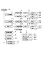
次に図3〜図5を参照して、制御系の構成および部品実装作業を実行するためのモータ制御に用いられる各種のデータについて説明する。図3において、制御装置20は処理演算機能とデータ記憶機能を備えており、以下に説明する各部を制御することにより、部品実装装置1に部品実装作業を実行させる。すなわち制御装置20がヘッド移動機構9、ノズル昇降機構11b、単位移載ヘッド11の集合体である実装ヘッド10を制御することにより、部品供給部4から部品を取り出して基板搬送機構2に位置決め保持された基板3に移送搭載する部品実装動作が実行され,このとき部品吸着機構24を制御することにより吸着ノズル11aによる部品の吸着保持および部品離脱が制御される。
Next, with reference to FIGS. 3 to 5, various data used for motor control for executing the configuration of the control system and component mounting work will be described. In FIG. 3, the
制御装置20が基板搬送機構2を制御することにより、基板3の搬入、位置決め、搬出が行われ、部品供給部4を制御することにより、実装ヘッド10による取り出し位置に部品が供給される。認識処理部25は、基板認識カメラ12、部品認識カメラ13の撮像結果を認識処理することにより、前述の基板3の位置認識および実装ヘッド10に保持された部品の位置検出を行う。そして制御装置20はこれらの認識結果を加味して、実装ヘッド10による基板3への部品搭載動作を行う。
When the
次に、ヘッド移動機構9を構成するY軸移動テーブル7、X軸移動テーブル8にそれぞれ内蔵されたY軸駆動機構7a、X軸駆動機構8a、単位移載ヘッド11に内蔵されたZ軸駆動機構11c、θ軸駆動機構11dの制御系について説明する。これらの駆動機構はいずれもサーボモータによるサーボ駆動系であり、それぞれサーボモータを駆動するためのX軸ドライバ21X、Y軸ドライバ21Y、Z軸ドライバ21Zおよびθ軸ドライバ21θを備えている。X軸ドライバ21X、Y軸ドライバ21Y、Z軸ドライバ21Zおよびθ軸ドライバ21θは、いずれも駆動電流出力部21a、負荷検出部21bおよびパルス処理部21cの機能を備えている。
Next, the Y-
各ドライバ21の駆動電流出力部21aから駆動電流を出力することにより、X軸モータ22X、Y軸モータ22Y、Z軸モータ22Z、θ軸モータ22θが回転駆動される。このとき、負荷検出部21bは各モータの駆動状態における負荷状態、すなわち当該モータの駆動電流を時系列的に検出して実効値を算出し、この実効値の定格負荷(定格電流値)に対する比率で表される負荷率を出力する。パルス処理部21cは、X軸モータ22X、Y軸モータ22Y、Z軸モータ22Z、θ軸モータ22θのそれぞれ付随して設けられたX軸エンコーダ23X、Y軸エンコーダ23Y、Z軸エンコーダ23Z、θ軸エンコーダ23θから出力されるパルスを受信してサーボ制御系のNC回路にフィードバックするパルス処理を行う。サーボ制御系のNC回路はここで示すドライバ21の機能に含めてもよく、またドライバ21と別個に設けられたサーボコントローラにその機能を持たせるようにしてもよい。
By outputting a drive current from the drive
図4に示すように、制御装置20は実装制御部26および記憶部31を備えている。まず記憶部31に記憶されるデータ内容、すなわち実装動作プログラム32、実装データ33、駆動パラメータ34、基準負荷率データ35について説明する。実装動作プログラム32は、実装制御部26が部品実装装置1の各部を制御して部品実装動作を実行させるための動作プログラムである。実装データ33は、前述の部品実装動作を各基板種を対象として実行するためのデータ、すなわち各基板における部品実装位置や実装される部品種、部品実装シーケンスなどについてのデータである。
As shown in FIG. 4, the
駆動パラメータ34は、モータの回転速度および回転加速度を組み合わせて構成されて負荷率を規定するパラメータである。基準負荷率データ35は、各モータにおいて通常使用状態における負荷状態の許容上限を示す基準となる負荷率についてのデータであり、定格負荷に対する割合によって示される。基準負荷率はサーボ駆動系の負荷状態を適正に制御する観点から経験的に設定されるものであり、本実施の形態では、(85%〜90%)を基準負荷率の範囲としている。
The
駆動パラメータ34は、上述のように、駆動時におけるモータの負荷率を規定するパラメータであり、基本的には駆動電流値の実効値によって規定される。ヘッド移動機構9などの作業機構を駆動するモータの負荷率は、当該モータの定格トルクに対応した電流値、すなわち定格電流値を保ったまま長時間駆動を継続する状態が負荷率は最も高く、実際の動作においては、最高加速度で加速状態を継続する動作がこれに相当する。しかしながら実際の作業動作においては、予め設定された移動速度に到達するまで加速を継続し、これ以降は加速がゼロの状態で速度を維持しながら到達点まで移動し、逆加速度によって減速して停止する動作形態が反復して実行される。このような動作形態におけるモータの負荷率は、一般には大きな加速度を長い時間継続するほど増大し、この結果移動対象物の速度はより高速となる。
As described above, the
したがって、モータの負荷率を動作条件設定時に規定する駆動パラメータ34としては、速度のみ、加速度のみ、速度と加速度の組み合わせのいずれを用いてもよい。すなわち動作時間に制約がある実際の作業動作のための動作条件の設定においては、高速の移動を実現しようとすれば必然的に加速度を大きくせざるを得ず、また大加速度で駆動すれば自ずと移動速度は高速となる。このような理由により本実施の形態においては、モータの負荷状態を規定する要素となる駆動パラメータとして、回転速度および回転加速度の組み合わせを用いる。すなわち回転加速度一定の条件で動作条件を設定する場合には、回転速度がモータの負荷率を規定する駆動パラメータとなり、また回転速度一定の条件の場合には、回転加速度がモータの負荷率を規定する駆動パラメータとなる。もちろん、回転速度および回転加速度の両方を変動させるようにしてもよい。
Therefore, any of speed alone, acceleration alone, or a combination of speed and acceleration may be used as the
次に実装制御部26の制御処理機能について説明する。まず実装制御部26は、ノズル昇降機構11bおよびヘッド移動機構9などの機構部を制御することにより、部品実装動作を実行させる。さらに実装制御部26は、駆動パラメータ設定処理部27、パラメータ指令部28、負荷低減処理部29a、負荷回復処理部29b、駆動条件設定処理部30の各機能部を有している。駆動パラメータ設定処理部27は、前述の駆動パラメータ34を設定する処理を行う。
Next, the control processing function of the mounting
ここで駆動パラメータ34としては、図5に示すように、全体動作パラメータ36、実装ターン別パラメータ37の2種類を予め設定して、場合に応じて適宜使い分けるようにしている。なお駆動パラメータ34の設定手法としては、実装動作プログラムから回転速度・回転加速度を数値的に求め、これらの数値に基づいて負荷演算を行う数値演算方法を用いてもよく、また模擬的に部品無しで部品実装機構に慣らし運転を行わせる際に、実際の負荷率を各ドライバの負荷検出部21bによって検出し、この実際の負荷率を参照して適正な駆動パラメータ34を設定するようにしてもよい。
Here, as the
全体動作パラメータ36は、部品実装装置1による部品実装動作を駆動するX軸モータ22X、Y軸モータ22Y、Z軸モータ22Z、θ軸モータ22θのそれぞれについて、部品実装動作開始から終了まで、同一の基準値36aを用いる場合の駆動パラメータである。すなわち、X軸モータ22X、Y軸モータ22Y、Z軸モータ22Z、θ軸モータ22θは、それぞれ全動作期間を通じて常に一定のpx、py、pz、pθの駆動パラメータを用いて駆動される。なお、低減率36b、回復率36cは、動作実行中に負荷率の監視を継続する過程において、適正な負荷率を維持するために駆動パラメータ34を低減または回復させる必要がある場合に用いられる数値であり、同様にX軸モータ22X、Y軸モータ22Y、Z軸モータ22Z、θ軸モータ22θのそれぞれについて予め設定されている。
The
次に実装ターン別パラメータ37は、実装ヘッド10が部品供給部4と基板3との間を1往復する実装ターン毎に、異なる値を個別に設定する場合に用いられる駆動パラメータである。すなわちここでは、駆動パラメータ設定処理部27は、各実装ターン毎の負荷率が当該モータの定格負荷に基づいて予め設定された基準負荷率、すなわち基準負荷率データ35として記憶部31に記憶された基準負荷率を超えないように、当該実装ターンにおける作業動作パターンに対応した駆動パラメータを、複数の実装ターンのそれぞれについて予め個別に設定する処理を行う。これにより、図5に示す実装ターン別パラメータ37が設定され、ターンNo.38に示す番号毎に、X軸モータ22X、Y軸モータ22Y、Z軸モータ22Z、θ軸モータ22θのそれぞれについて個別値37aが設定される。
Next, the mounting turn-
ここで、図10,図11を参照して、各実装ターン毎に異なる駆動パラメータを設定することの意義を説明する。図10(a)は、1実装ターンにおいて実装ヘッド10によって基板3に電子部品を実装する複数の部品実装点3aが近接しており、部品実装点3aの分布範囲を示すターン別実装領域R1が狭い場合を示している。この場合には、実装ヘッド10は、部品供給部4のテープフィーダ5から複数(ここでは4個)の電子部品をピックアップした後、部品認識カメラ13の上方をX方向に所定のスキャン速度で移動して、実装ヘッド10に保持した電子部品を撮像する。そしてその後、実装ヘッド10は基板搬送機構2に保持された基板3上に移動して、複数(ここでは4)の部品実装点3aに電子部品を連続的に実装する。
Here, the significance of setting different driving parameters for each mounting turn will be described with reference to FIGS. In FIG. 10A, a plurality of
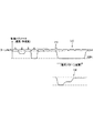
図11(a)は、このときのX、Y、θ、Z(ここでは、Z1〜Znまでの複数軸)各軸のモータの回転速度パターンを示している。図11(a)において、破線枠Aにて示すZ軸の速度パターンは、部品供給部4において複数のテープフィーダ5を対象として、複数の単位移載ヘッド11の吸着ノズル11aを昇降させるためのZ軸の速度パターンを示しており、このZ軸による吸着ノズル11aの昇降が終了した後に、実装ヘッド10は保持した電子部品の認識のために部品認識カメラ13の上方へ移動する。この速度パターンにおいて、動作開始からこの移動完了までにはT1の時間を要している。破線枠Bにて示すX軸の速度パターンは、電子部品を取り出した後の実装ヘッド10が部品認識カメラ13の上方を一定のスキャン速度でX方向に移動する際の速度パターンを示しており、このスキャン動作にはT2の時間を要している。このスキャン動作においては、画像取得上スキャン動作を所定速度に保持する必要があり、常に所定のT2の時間を要する。
FIG. 11 (a) shows the rotational speed pattern of the motor of each axis of X, Y, θ, Z (here, a plurality of axes from Z1 to Zn) at this time. In FIG. 11A, the Z-axis speed pattern indicated by the broken line frame A is for moving the
そしてこの後、実装ヘッド10は基板搬送機構2に位置決めされた基板3上に移動して複数の部品実装点3aに保持した電子部品を順次実装する。破線枠Cにて示すX軸、Y軸、θ軸の速度パターンは、吸着ノズル11aによる部品実装時の位置補正動作を示しており、破線枠Dにて示すZ軸の速度パターンは、基板3において吸着ノズル11aを昇降させるためのZ軸の駆動動作を示している。この実装ヘッド10による部品実装動作には、スキャン動作終了からT3の時間を要している。
Thereafter, the mounting
図11(a)に示す速度パターンは、図10(a)に示すように、部品実装点3aの分布範囲を示すターン別実装領域R1が狭い場合に対応した速度パターンとなっていることから、短時間の内に加減速を高頻度で反復する動作パターン、換言すれば駆動パラメータを大きな値に設定する必要がある動作パターンとなっている。このため、駆動パラメータの設定如何によっては、X軸において負荷率が基準負荷率を超える過負荷状態を招くおそれがある。このような場合には、過負荷状態の発生を予め防止するため、図11(b)に示すような速度パターンが実現されるような駆動パラメータが設定される。
Since the speed pattern shown in FIG. 11A is a speed pattern corresponding to the case where the turn-by-turn mounting region R1 indicating the distribution range of the
図11(b)においては、図11(a)においてそれぞれ時間T1、T3に設定されているX軸の速度パターンを、時間T1、T3よりも長い時間T1*、T3*にて実行するような速度パターンとし、この速度パターンに対応したX軸の駆動パラメータが設定される。ここで、時間T2については、前述の理由で変更することができず、常に固定の時間T2に設定される。このため、時間T1、T3における駆動パラメータの低減率と、時間T2における駆動パラメータの低減率とは異なった値に設定される。 In FIG. 11B, the X-axis velocity patterns set at times T1 and T3 in FIG. 11A are executed at times T1 * and T3 * longer than the times T1 and T3, respectively. A speed pattern is set, and X-axis drive parameters corresponding to the speed pattern are set. Here, the time T2 cannot be changed for the reason described above, and is always set to a fixed time T2. For this reason, the drive parameter reduction rate at times T1 and T3 and the drive parameter reduction rate at time T2 are set to different values.
すなわち上述例においては、負荷低減処理部29aは、複数のモータのうち、部品認識カメラ13による撮像のためのスキャン動を行うX軸モータ22Xのように、特定の動作特性が所望されている作業動作を実行するモータについては、この動作特性に応じて予め個別に設定された異なる低減率を用いて負荷低減処理を行うようにしている。このとき、Y軸、θ軸については、X軸と動作が同期する速度パターンが実現されるように駆動パラメータを設定することが望ましい。
In other words, in the above-described example, the load
また図10(b)は、1実装ターンにおいて実装ヘッド10によって基板3に電子部品を実装する部品実装点3aの分布範囲を示すターン別実装領域R2が広い場合を示している。この場合には、短時間の内に加減速を高頻度で反復する度合いが少なく、X軸、Y軸、θ軸の駆動パラメータを比較的大きな値に設定しても負荷率はあまり高くならず、過負荷状態を招くおそれがない。したがってこのような場合には、図11(a)に示すような速度パターンを適用しても差し支えない。このように、複数の実装ターンのそれぞれについて、部品実装点3aの分布範囲の大きさなどの作業動作パターンに応じて、各軸のモータの回転速度・回転加速度によって規定される駆動パラメータを設定することにより、実装ターン毎の作業負荷が大きくばらつく場合にあっても、過負荷状態を防止するとともに動作効率を極力維持することが可能となる。
FIG. 10B shows a case where a turn-specific mounting region R2 indicating a distribution range of
パラメータ指令部28は、上述のように設定される駆動パラメータ34を記憶部31から読み出して、X軸ドライバ21X、Y軸ドライバ21Y、Z軸ドライバ21Zおよびθ軸ドライバ21θに対して出力する処理を行う。これにより、X軸ドライバ21X、Y軸ドライバ21Y、Z軸ドライバ21Zおよびθ軸ドライバ21θは、指示された駆動パラメータ34に基づいて.それぞれX軸モータ22X、Y軸モータ22Y、Z軸モータ22Z、θ軸モータ22θを駆動する。
The
負荷低減処理部29aは、X軸ドライバ21X、Y軸ドライバ21Y、Z軸ドライバ21Zおよびθ軸ドライバ21θの負荷検出部21bによって検出された当該モータの負荷率を監視し、これら複数のモータの少なくとも1つにおいて、図8の事象F1に示すように、負荷率が当該モータの定格負荷に基づいて予め設定された基準負荷率を超えた場合には、負荷率が予め設定された低減率Δp1(Δpx1,Δpy1,Δpz1,Δpθ1,)で減少するように、パラメータ指令部28から出力される駆動パラメータ34を変更させる負荷低減処理を行う。すなわち負荷低減処理部29aが記憶部31から低減率36b(Δpx1,Δpy1,Δpz1,Δpθ1)を読み取ってパラメータ指令部28に指令することにより、パラメータ指令部28から出力される駆動パラメータ34、基準値36aに対して低減率36bに相当する低減分だけ減少する。
The load
なお、駆動パラメータ34として実装ターン別パラメータ37を適用する場合には、負荷低減処理の態様として上述と異なる負荷低減処理を行うようにしてもよい。まず複数実装ターンを対象とする部品実装作業実行中に、いずれかの実装ターンにおいて図9に示す事象F3のように、作業動作パターンの変更、例えば特定のテープフィーダ5についての部品切れなど、予め設定されていた実装動作シーケンスが実行できないことによる実装順序の変更などが生じた場合には、図9(イ)に示すような対応処理を行う。すなわち当該実装ターンについて設定されている駆動パラメータ34を、当該基板3を対象とする各実装ターンに設定されている駆動パラメータ34のうち最も低い負荷率に対応した駆動パラメータ(MIN.)に変更させる負荷低減処理を行う。この対応処理は、負荷率が基準負荷率(MAX.)を超えることのないよう、駆動パラメータ34を極力安全側に設定することを意味している。
Note that, when the mounting turn-
もちろん、図9(ロ)に示すように、いずれかの実装ターンにおいて図9に示す事象F3が生じた後において、図8において説明したような負荷低減処理、負荷回復処理および駆動条件設定処理を実行することにより、実際の負荷率をできるだけ基準負荷率に近づけるようにしてもよい。さらに、実装ターン1,2,3・・を順次対象として作業を実行する過程において、当初から各実装ターンのそれぞれを対象として図8において説明したような負荷低減処理、負荷回復処理および駆動条件設定処理を実行するようにしてもよい。 Of course, as shown in FIG. 9B, after the event F3 shown in FIG. 9 occurs in any mounting turn, the load reduction processing, load recovery processing, and drive condition setting processing described in FIG. 8 are performed. By executing, the actual load factor may be as close to the reference load factor as possible. Further, in the process of sequentially performing the work on the mounting turns 1, 2, 3,..., The load reduction process, the load recovery process, and the drive condition setting as described in FIG. Processing may be executed.
負荷回復処理部29bは、負荷率が低減された状態で予め設定された作業実行条件にしたがって、例えば所定の基板枚数、所定の実装ターン回数などを対象として部品実装作業を継続実行する過程において、負荷検出部21bによって検出される負荷率が基準負荷率データ35に規定される基準負荷率を超える状態が発生しなかった場合には、負荷率が予め設定された回復率Δp2(Δpx2,Δpy2,Δpz2,Δpθ2)で段階的に増加するように駆動パラメータ34を変更させる負荷率回復処理を行う。すなわち、負荷回復処理部29bが記憶部31から回復率36c(Δpx2,Δpy2,Δpz2,Δpθ2)を読み取ってパラメータ指令部28に指令することにより、パラメータ指令部28から出力される駆動パラメータ34は、基準値36aに対して回復率36cに相当する回復分だけ増加する。そしてこの負荷回復処理は、負荷率が基準負荷率データ35に規定される負荷率に到達するまで反復して行われる。
In the process of continuously executing the component mounting work for a predetermined number of boards, a predetermined number of mounting turns, and the like according to the work execution conditions set in advance with the load factor reduced, If the load factor detected by the
さらに負荷回復処理部29bによる負荷回復処理の態様には、各種のバリエーションが可能である。例えば前述の負荷低減処理実行後に、負荷率が低減された状態で予め設定された作業実行条件にしたがって部品実装作業を継続実行する過程において、作業動作パターンに変更がない実装ターンを作業対象とする場合には、当該実装ターンに適用される駆動パラメータを、予め設定された変更前の駆動パラメータ、すなわち当該実装ターンに本来適用されるべく設定されていたに駆動パラメータ変更して、負荷率を回復させるようにしてもよい。 Furthermore, various variations are possible for the mode of the load recovery processing by the load recovery processing unit 29b. For example, in the process of continuously executing component mounting work according to preset work execution conditions in a state where the load factor is reduced after executing the above-described load reduction processing, a mounting turn whose work operation pattern is not changed is set as a work target. In this case, the drive parameter applied to the mounting turn is changed to the driving parameter before change that is set in advance, that is, the driving parameter originally set to be applied to the mounting turn, to restore the load factor. You may make it make it.
そして駆動条件設定処理部30は、上述の負荷回復処理を反復して実行する過程において、駆動パラメータが増大することによって、図8の事象F2に示すように、負荷率が基準負荷率を再度超えたならば、最後の負荷率回復処理を実行する直前の駆動パラメータ34を、確定駆動パラメータとして設定する駆動条件確定処理を行う。すなわち、これ以降は実装制御部26は,このようにして設定された確定駆動パラメータにしたがって部品実装作業を継続実行させる。これにより、負荷率が基準負荷率を超えず、且つ極力動作効率の高い動作条件で部品実装作業を実行することが可能となる。
In the process of repeatedly executing the load recovery process described above, the drive condition setting
次に部品実装装置1におけるモータ制御処理の実際例について、図6,図7のフローに則して、各図を参照しながら説明する。図6,図7に示す処理は、駆動パラメータ34として全体動作パラメータ36を用いる場合、すなわち複数の実装ターンを連続して実行する部品実装作業を通して同一の駆動パラメータを固定して用いる場合にも適用され、また駆動パラメータ34として実装ターン別パラメータ37を用いる場合、すなわち各実装ターン毎に必要に応じて異なる駆動パラメータを用いる場合にも適用される。
Next, an actual example of motor control processing in the
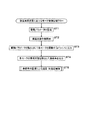
まず図6において、パラメータ指令部28による駆動パラメータの指令に先立って、駆動パラメータ設定処理部27の処理機能により駆動パラメータ34の設定を行う(ST1)。ここで部品実装作業を通して同一の駆動パラメータ34を固定して用いる場合には、図5に示す全体動作パラメータ36が設定され、記憶部31に記憶される。また各実装ターン毎に必要に応じて異なる駆動パラメータ34を用いる場合には、実装ターンにおける作業動作パターンに対応した駆動パラメータ34を、複数の実装ターンのそれぞれについて個別に設定し、記憶部31に実装ターン別パラメータ37として記憶させる(ST1)。すなわち、実装ヘッド10が部品供給部4と基板3との間を1往復する実装ターン毎に、負荷率が当該モータの定格負荷に基づいて予め設定された基準負荷率を超えないように、当該実装ターンにおける作業動作パターンに対応した駆動パラメータ34を、複数の実装ターンのそれぞれについて個別に設定する(駆動パラメータ設定処理工程)。そしてこの後、部品実装装置1による部品実装作業が開始される(ST2)。
First, in FIG. 6, prior to the drive parameter command by the
次いで、駆動パラメータ34を読み出して、各モータを駆動するドライバに対して出力する(ST3)。すなわち、複数のモータ(X軸モータ22X、Y軸モータ22Y、Z軸モータ22Z、θ軸モータ22θ)について、回転速度および回転加速度を組み合わせて構成されて負荷率を規定する駆動パラメータ34を、各モータを駆動するドライバに対して出力する(パラメータ指令工程)。駆動パラメータ34として実装ターン別パラメータ37を用いる場合には、このパラメータ指令工程は、順次実行される各実装ターンを対象とする部品実装作業毎に行われる。
Next, the
この後、各モータの負荷状態を検出して負荷率を出力する(ST3)。すなわち、駆動状態における複数のモータ(X軸モータ22X、Y軸モータ22Y、Z軸モータ22Z、θ軸モータ22θ)の負荷状態を、当該モータに対応するドライバ21の負荷検出部21bによって時系列的に検出して、それぞれのモータの定格負荷に対する負荷率を出力する(負荷検出工程)。そしてこれ以降、負荷状態が過負荷となることを未然に防止するため、負荷率の監視による速度・加速度制御が実行される(ST5)。
Thereafter, the load state of each motor is detected and the load factor is output (ST3). That is, the load states of a plurality of motors (
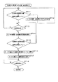
図7は、(ST5)にて実行される処理の詳細を示すものである。すなわちここでは、各モータに対応するドライバ21の負荷検出部21bによって負荷率を監視し、複数のモータの少なくとも1つにおいて負荷率が当該モータの定格負荷に基づいて予め設定された基準負荷率レベル(図8参照)を超えたか否かを判定する(ST11)。ここで、YESであれば、すなわち図8に事象F3で示す状態のように、基準負荷率レベルを超えた場合には、負荷低減処理部29aによって当該モータの速度・加速度、換言すれば駆動パラメータ34を所定割合(低減率Δp1・・図5に示す低減率36b参照)で低減する(ST12)。すなわちここでは負荷率が予め設定された低減率で減少するように、駆動パラメータを変更させる負荷低減処理を行う(負荷低減処理工程)。
FIG. 7 shows the details of the process executed in (ST5). That is, here, the load factor is monitored by the
そしてこの後、(ST11)戻って負荷率の監視を継続し、(ST11)にてNOであれば、すなわち負荷率が基準負荷レベルを下回っていれば、正常な駆動状態であると判断して作業動作を継続実行する。そしてこの状態で、所定数の生産が実行されたか否かを判断し(ST13)、NOであれば(ST11)を実行しながら作業動作を継続する。そして(ST13)において所定数の生産が完了してYESであれば、すなわち予め設定された作業実行条件にしたがって部品実装作業を継続実行する過程において、負荷率が基準負荷率を超える状態が発生しなかった場合には、負荷回復処理部29bによって当該モータの速度・加速度を所定割合(回復率Δp2・・図5に示す回復率36c参照)で増加させるように、駆動パラメータ34を変更する(ST14)。
After that, (ST11) returns to continue monitoring the load factor. If (NO) in (ST11), that is, if the load factor is below the reference load level, it is determined that the drive state is normal. Continue working. In this state, it is determined whether or not a predetermined number of productions have been executed (ST13). If NO, the work operation is continued while executing (ST11). In (ST13), if the predetermined number of productions are completed and YES, that is, a state in which the load factor exceeds the reference load factor occurs in the process of continuously executing the component mounting work according to the preset work execution conditions. If not, the
そしてこの後さらに負荷率が、当該モータの定格負荷に基づいて予め設定された基準負荷率レベルを超えたか否かを判定する(ST15)。ここでNOであれば、すなわち負荷率がなお基準負荷レベルを下回っていれば、(ST13)に戻って、以降の処理を同様に反復実行する。これにより、一旦低減された負荷率は、図8に示すように、回復率Δp2で複数回(ここでは2回)増加し、基準負荷率レベルに接近する。すなわちここでは負荷率が予め設定された回復率Δp2で段階的に増加するように、負荷回復処理部29bによって駆動パラメータを変更させる負荷率回復処理を反復して行う(負荷回復処理工程)。 Thereafter, it is further determined whether or not the load factor has exceeded a preset reference load factor level based on the rated load of the motor (ST15). If “NO” here, that is, if the load factor is still below the reference load level, the process returns to (ST13), and the subsequent processing is repeated in the same manner. As a result, as shown in FIG. 8, the load factor once reduced increases a plurality of times (here, twice) at the recovery rate Δp2, and approaches the reference load factor level. That is, here, the load factor recovery process of changing the drive parameter by the load recovery processor 29b is repeatedly performed so that the load factor increases stepwise at a preset recovery factor Δp2 (load recovery processing step).
この負荷回復処理において、当該モータの速度・加速度をさらに増加させることによって、または何らかの外的条件によって、図8の事象F2に示すように、負荷率が基準負荷率レベルを超える状態が再度発生した場合には、当該モータの速度・加速度を規定する駆動パラメータ34を、前回の増加前のレベル,すなわちこの状態より回復率Δp2だけ低減させたレベルに戻す(ST16)。これにより、当該モータの負荷率は、基準負荷率レベルに極力近く、且つこれを超えることのない安定したレベルに設定される。
In this load recovery process, a state in which the load factor exceeds the reference load factor level again occurs as shown in event F2 in FIG. 8 by further increasing the speed / acceleration of the motor or by some external condition. In this case, the
そしてこの状態における当該モータの速度・加速度の設定状態を確定速度・加速度として記憶する(ST18)。すなわち、駆動条件設定処理部30によって、最後の負荷率回復処理を実行する直前の駆動パラメータを確定駆動パラメータとして設定する駆動条件確定処理を行う(駆動条件設定処理工程)。この後、このようにして設定された確定駆動パラメータを用いて部品実装の生産作業を継続実行し、必要数の生産が確認されることにより(ST18)、生産を終了する。
Then, the setting state of the motor speed and acceleration in this state is stored as the determined speed and acceleration (ST18). That is, the drive condition setting
上記説明したように、本実施の形態に示す部品実装装置におけるモータ制御方法においては、モータの負荷率が当該モータの定格負荷に基づいて予め設定された基準負荷率を超えた場合には、負荷率が予め設定された低減率で減少するように駆動パラメータを変更させる負荷低減処理を行い、負荷率が低減された状態で予め設定された作業実行条件にしたがって部品実装作業を継続実行する過程において、負荷率が基準負荷率を超える状態が発生しなかった場合には、負荷率が予め設定された回復率で段階的に増加するように駆動パラメータを変更する負荷率回復処理を反復して行うようにしている。さらに複数の実装ターンのそれぞれについて、作業動作パターンに応じて、各軸のモータの回転速度・回転加速度によって規定される駆動パラメータを設定するようにしている。これにより、実装ターン毎の作業負荷が大きくばらつく場合にあっても、過負荷状態を防止するとともに動作効率を極力維持することが可能となり、過負荷状態の確実な防止と動作効率の維持向上を両立させることができる。 As described above, in the motor control method in the component mounting apparatus shown in the present embodiment, when the load factor of the motor exceeds a reference load factor set in advance based on the rated load of the motor, the load In the process of performing the load reduction process to change the drive parameter so that the rate decreases at a preset reduction rate, and continuously executing the component mounting work according to the preset work execution condition in a state where the load factor is reduced When a state in which the load factor exceeds the reference load factor does not occur, the load factor recovery process for changing the drive parameter is repeatedly performed so that the load factor increases stepwise at a preset recovery factor. I am doing so. Further, for each of the plurality of mounting turns, drive parameters defined by the rotational speed and rotational acceleration of the motor of each axis are set according to the work operation pattern. This makes it possible to prevent overload conditions and maintain operating efficiency as much as possible even when the work load for each mounting turn varies widely, thereby reliably preventing overload conditions and maintaining and improving operating efficiency. Both can be achieved.
本発明の部品実装装置および部品実装装置におけるモータ制御方法は、過負荷状態の確実な防止と動作効率の維持向上を両立させることができるという効果を有し、吸着ノズルを備えた実装ヘッドを部品供給部と基板との間で往復移動させることにより部品を部品供給部から取り出して基板に移送搭載する部品実装分野において有用である。 INDUSTRIAL APPLICABILITY The component mounting apparatus and the motor control method in the component mounting apparatus according to the present invention have an effect that it is possible to achieve both the reliable prevention of an overload state and the maintenance and improvement of the operation efficiency. This is useful in the field of component mounting in which a component is taken out from the component supply unit by reciprocating between the supply unit and the substrate, and transferred and mounted on the substrate.
1 部品実装装置
2 基板搬送機構
3 基板
4 部品供給部
5 テープフィーダ
9 ヘッド移動機構
10 実装ヘッド
11 単位移載ヘッド
11a 吸着ノズル
DESCRIPTION OF
Claims (8)
前記ノズル昇降機構およびヘッド移動機構を制御する実装制御部と、
前記ノズル昇降機構およびヘッド移動機構を駆動する複数のモータと、
前記複数のモータを駆動するとともに駆動状態における前記複数のモータの負荷状態を時系列的に検出してそれぞれのモータの定格負荷に対する負荷率を出力する負荷検出部を備えたドライバとを有し、
さらに前記実装制御部が、
前記モータの回転速度および回転加速度を組み合わせて構成されて前記負荷率を規定する駆動パラメータを前記ドライバに対して出力するパラメータ指令部と、
前記実装ヘッドが部品供給部と基板との間を1往復する実装ターン毎に、前記負荷率が当該モータの定格負荷に基づいて予め設定された基準負荷率を超えないように、当該実装ターンにおける作業動作パターンに対応した前記駆動パラメータを、複数の実装ターンのそれぞれについて予め個別に設定する駆動パラメータ設定処理部とを備えたことを特徴とする部品実装装置。 A mounting head equipped with a suction nozzle that moves up and down by a nozzle lifting mechanism is reciprocated between a component supply unit and a substrate by a head moving mechanism, whereby the component is taken out from the component supply unit by the suction nozzle and transferred to the substrate A component mounting apparatus for performing component mounting work,
A mounting control unit for controlling the nozzle lifting mechanism and the head moving mechanism;
A plurality of motors for driving the nozzle lifting mechanism and the head moving mechanism;
A driver having a load detection unit that drives the plurality of motors and detects a load state of the plurality of motors in a driving state in time series and outputs a load ratio with respect to a rated load of each motor;
Further, the mounting control unit
A parameter command unit configured to output to the driver a drive parameter configured to combine the rotational speed and rotational acceleration of the motor and define the load factor;
For each mounting turn in which the mounting head makes one reciprocation between the component supply unit and the board, the load factor does not exceed a reference load factor set in advance based on the rated load of the motor. A component mounting apparatus, comprising: a drive parameter setting processing unit that individually sets in advance each of the plurality of mounting turns the driving parameter corresponding to the work operation pattern.
前記複数のモータについて、回転速度および回転加速度を組み合わせて構成されて前記負荷率を規定する駆動パラメータを各モータを駆動するドライバに対して出力するパラメータ指令工程と、
駆動状態における前記複数のモータの負荷状態を時系列的に検出してそれぞれのモータの定格負荷に対する負荷率を出力する負荷検出工程とを含み、
さらに前記パラメータ指令工程に先立って、前記実装ヘッドが部品供給部と基板との間を1往復する実装ターン毎に、前記負荷率が当該モータの定格負荷に基づいて予め設定された基準負荷率を超えないように、当該実装ターンにおける作業動作パターンに対応した前記駆動パラメータを、複数の実装ターンのそれぞれについて個別に設定する駆動パラメータ設定処理工程を予め実行することを特徴とする部品実装装置におけるモータ制御方法。 A mounting head equipped with a suction nozzle that moves up and down by a nozzle lifting mechanism is reciprocated between a component supply unit and a substrate by a head moving mechanism, whereby the component is taken out from the component supply unit by the suction nozzle and transferred to the substrate In a component mounting apparatus that performs a component mounting operation, a motor control method in a component mounting apparatus that controls a plurality of motors that drive the nozzle lifting mechanism and the head moving mechanism,
A parameter commanding step for outputting a driving parameter that is configured by combining rotational speed and rotational acceleration and that defines the load factor to a driver that drives each motor for the plurality of motors;
A load detection step of detecting a load state of the plurality of motors in a driving state in time series and outputting a load factor with respect to a rated load of each motor,
Further, prior to the parameter command step, the load factor is set to a reference load factor set in advance based on the rated load of the motor for each mounting turn in which the mounting head makes one round trip between the component supply unit and the board. A motor in a component mounting apparatus, wherein a drive parameter setting processing step for setting the drive parameters corresponding to the work operation pattern in the mounting turn individually for each of a plurality of mounting turns is performed in advance so as not to exceed Control method.
Priority Applications (1)
| Application Number | Priority Date | Filing Date | Title |
|---|---|---|---|
| JP2010263370A JP5440480B2 (en) | 2010-11-26 | 2010-11-26 | Component mounting apparatus and motor control method in component mounting apparatus |
Applications Claiming Priority (1)
| Application Number | Priority Date | Filing Date | Title |
|---|---|---|---|
| JP2010263370A JP5440480B2 (en) | 2010-11-26 | 2010-11-26 | Component mounting apparatus and motor control method in component mounting apparatus |
Publications (2)
| Publication Number | Publication Date |
|---|---|
| JP2012114326A true JP2012114326A (en) | 2012-06-14 |
| JP5440480B2 JP5440480B2 (en) | 2014-03-12 |
Family
ID=46498197
Family Applications (1)
| Application Number | Title | Priority Date | Filing Date |
|---|---|---|---|
| JP2010263370A Active JP5440480B2 (en) | 2010-11-26 | 2010-11-26 | Component mounting apparatus and motor control method in component mounting apparatus |
Country Status (1)
| Country | Link |
|---|---|
| JP (1) | JP5440480B2 (en) |
Cited By (2)
| Publication number | Priority date | Publication date | Assignee | Title |
|---|---|---|---|---|
| JP2014165278A (en) * | 2013-02-22 | 2014-09-08 | Hitachi High-Tech Instruments Co Ltd | Method of controlling motor in mounting work device, and mounting work device |
| JP2021082833A (en) * | 2021-02-16 | 2021-05-27 | 株式会社Fuji | Maintenance management device |
Citations (4)
| Publication number | Priority date | Publication date | Assignee | Title |
|---|---|---|---|---|
| JPH09282020A (en) * | 1996-04-16 | 1997-10-31 | Denso Corp | Servo motor driving device |
| JP2006013113A (en) * | 2004-06-25 | 2006-01-12 | Hitachi High-Tech Instruments Co Ltd | Electronic component mounter and mounting method |
| JP2006253616A (en) * | 2005-03-14 | 2006-09-21 | Matsushita Electric Ind Co Ltd | Component mounting order determination method, component mounting method and component mounting machine |
| JP2009032871A (en) * | 2007-07-26 | 2009-02-12 | Juki Corp | Head driving device, mounter, and dispenser |
-
2010
- 2010-11-26 JP JP2010263370A patent/JP5440480B2/en active Active
Patent Citations (4)
| Publication number | Priority date | Publication date | Assignee | Title |
|---|---|---|---|---|
| JPH09282020A (en) * | 1996-04-16 | 1997-10-31 | Denso Corp | Servo motor driving device |
| JP2006013113A (en) * | 2004-06-25 | 2006-01-12 | Hitachi High-Tech Instruments Co Ltd | Electronic component mounter and mounting method |
| JP2006253616A (en) * | 2005-03-14 | 2006-09-21 | Matsushita Electric Ind Co Ltd | Component mounting order determination method, component mounting method and component mounting machine |
| JP2009032871A (en) * | 2007-07-26 | 2009-02-12 | Juki Corp | Head driving device, mounter, and dispenser |
Cited By (3)
| Publication number | Priority date | Publication date | Assignee | Title |
|---|---|---|---|---|
| JP2014165278A (en) * | 2013-02-22 | 2014-09-08 | Hitachi High-Tech Instruments Co Ltd | Method of controlling motor in mounting work device, and mounting work device |
| JP2021082833A (en) * | 2021-02-16 | 2021-05-27 | 株式会社Fuji | Maintenance management device |
| JP7068759B2 (en) | 2021-02-16 | 2022-05-17 | 株式会社Fuji | Maintenance equipment |
Also Published As
| Publication number | Publication date |
|---|---|
| JP5440480B2 (en) | 2014-03-12 |
Similar Documents
| Publication | Publication Date | Title |
|---|---|---|
| JP5822819B2 (en) | Electronic component mounting method and surface mounter | |
| JP5440480B2 (en) | Component mounting apparatus and motor control method in component mounting apparatus | |
| JP5488427B2 (en) | Component mounting apparatus and motor control method in component mounting apparatus | |
| EP2961253B1 (en) | Component mounting system and bulk component determination method used for same | |
| EP2876990A1 (en) | Work system and work machines for substrates | |
| JP6294891B2 (en) | Installation position optimization program | |
| JP4850751B2 (en) | Surface mount machine | |
| JP5085527B2 (en) | Drive motor control method, drive motor control device, and electronic component mounting device | |
| JP4485267B2 (en) | Electronic component mounting apparatus and electronic component mounting method | |
| JP6139948B2 (en) | Component mounting equipment | |
| JP6678057B2 (en) | Electronic component mounting machine | |
| JP7307546B2 (en) | Board working device | |
| JP2018120920A (en) | Component loading machine | |
| JP5533534B2 (en) | Component mounting apparatus and positioning control method in component mounting apparatus | |
| JP5102745B2 (en) | Component mounting method and mounting machine | |
| JP5291889B2 (en) | Automatic machine automatic operation control method | |
| JP7339904B2 (en) | Data creation device and component mounting system | |
| US11868113B2 (en) | Servo amplifier system | |
| JP7088809B2 (en) | Work work device, work work system, and control method of work work device | |
| JP7339906B2 (en) | Mounting management device | |
| JP4339141B2 (en) | Surface mount machine | |
| WO2018003102A1 (en) | Production program optimization system and production management system | |
| JP2017220538A (en) | Component mounting apparatus and component mounting method | |
| JP4805084B2 (en) | Imaging control apparatus and surface mounter | |
| JP6832454B2 (en) | Parts mounting machine |
Legal Events
| Date | Code | Title | Description |
|---|---|---|---|
| A621 | Written request for application examination |
Free format text: JAPANESE INTERMEDIATE CODE: A621 Effective date: 20130121 |
|
| RD01 | Notification of change of attorney |
Free format text: JAPANESE INTERMEDIATE CODE: A7421 Effective date: 20130213 |
|
| A977 | Report on retrieval |
Free format text: JAPANESE INTERMEDIATE CODE: A971007 Effective date: 20131111 |
|
| TRDD | Decision of grant or rejection written | ||
| A01 | Written decision to grant a patent or to grant a registration (utility model) |
Free format text: JAPANESE INTERMEDIATE CODE: A01 Effective date: 20131119 |
|
| A61 | First payment of annual fees (during grant procedure) |
Free format text: JAPANESE INTERMEDIATE CODE: A61 Effective date: 20131202 |
|
| R151 | Written notification of patent or utility model registration |
Ref document number: 5440480 Country of ref document: JP Free format text: JAPANESE INTERMEDIATE CODE: R151 |