JP2012112559A - Remote controller of heat source system - Google Patents
Remote controller of heat source system Download PDFInfo
- Publication number
- JP2012112559A JP2012112559A JP2010260598A JP2010260598A JP2012112559A JP 2012112559 A JP2012112559 A JP 2012112559A JP 2010260598 A JP2010260598 A JP 2010260598A JP 2010260598 A JP2010260598 A JP 2010260598A JP 2012112559 A JP2012112559 A JP 2012112559A
- Authority
- JP
- Japan
- Prior art keywords
- display
- screen
- heat source
- unit
- control unit
- Prior art date
- Legal status (The legal status is an assumption and is not a legal conclusion. Google has not performed a legal analysis and makes no representation as to the accuracy of the status listed.)
- Pending
Links
Images


Abstract
Description
本発明は、給湯配管への湯の供給や温水端末への温水の供給を行う熱源システムのリモコン装置に関する。 The present invention relates to a remote control device of a heat source system that supplies hot water to a hot water supply pipe and hot water to a hot water terminal.
従来より、電気、ガス等のエネルギーを消費するエネルギー消費装置と無線通信を行って、エネルギー消費装置を遠隔操作するリモコン装置において、1ヶ月あたりのエネルギー消費量の目標値を設定して現時点でのエネルギーの使用実績値と比較し、目標値と使用実績値との差の比に応じてパターンを変化させる表示(省エネ促進表示)を行うようにした構成が提案されている(例えば、特許文献1参照)。 Conventionally, a remote control device that remotely controls an energy consuming device by performing wireless communication with an energy consuming device that consumes energy, such as electricity and gas, sets a target value for energy consumption per month and A configuration has been proposed in which a display (energy saving promotion display) is performed in which the pattern is changed in accordance with the ratio of the difference between the target value and the actual use value compared to the actual use value of the energy (for example, Patent Document 1). reference).
また、暖房温水システムにおいて、複数の温水暖房端末を遠隔操作する集中リモコンの構成として、集中リモコンの表示部に、各温水暖房端末用の操作画面を切替えて表示するようにした構成が提案されている(例えば、特許文献2参照)。 In addition, in the heating and hot water system, a configuration has been proposed in which the operation screen for each hot water heating terminal is switched and displayed on the display unit of the central remote control as the configuration of the central remote control for remotely operating a plurality of hot water heating terminals. (For example, refer to Patent Document 2).
熱源システムのリモコン装置の表示部には、給湯運転や暖房運転の設定状況及び実行状況等の種々の情報が表示される。そのため、省エネ促進表示を行うための空きスペースが僅かなものとなって、省エネ促進表示のサイズが小さくなり、使用者の省エネ意識を高める効果が低くなるという不都合があった。 Various information such as the setting status and execution status of the hot water supply operation and the heating operation are displayed on the display unit of the remote control device of the heat source system. Therefore, there is a disadvantage that the space for performing the energy saving promotion display becomes small, the size of the energy saving promotion display is reduced, and the effect of raising the user's energy saving awareness is reduced.
本発明は上記不都合を解消し、省エネ促進表示による使用者の省エネ意識の向上効果を高めることができる熱源システムのリモコン装置を提供することを目的とする。 An object of the present invention is to provide a remote control device of a heat source system that can solve the above-mentioned disadvantages and can enhance the effect of improving the user's energy saving awareness by the energy saving promotion display.
本発明は上記目的を達成するためになされたものであり、熱源機を遠隔操作するための操作部と、表示部と、前記熱源機におけるエネルギー消費量を算出するエネルギー消費量算出部と、該エネルギー消費量算出部により算出されたエネルギー消費量に基づいて、省エネルギーを促すための省エネマークを、前記表示部に表示させる表示制御部とを備えた熱源機のリモコン装置において、前記表示制御部は、前記表示部における前記省エネマーク以外の表示状況に応じて、前記省エネマークの表示位置を変更することを特徴とする(第1発明)。 The present invention has been made to achieve the above object, an operation unit for remotely operating a heat source machine, a display unit, an energy consumption calculation unit for calculating an energy consumption amount in the heat source machine, In the remote control device for a heat source apparatus, the display control unit includes a display control unit that displays an energy saving mark for promoting energy saving on the display unit based on the energy consumption calculated by the energy consumption calculation unit. The display position of the energy saving mark is changed according to the display status of the display unit other than the energy saving mark (first invention).
第1発明によれば、前記表示制御部により、前記省エネマークの表示位置が、前記表示部における前記省エネマーク以外の表示状況に応じて変更される。これにより、前記省エネマークの表示位置を固定する場合に比べて、前記省エネマークの表示位置を使用者が視認し易い位置に変更することができるため、前記省エネマークによる使用者の省エネ意識の向上効果を高めることができる。 According to 1st invention, the display position of the said energy saving mark is changed by the said display control part according to display conditions other than the said energy saving mark in the said display part. As a result, the display position of the energy saving mark can be changed to a position that is easy for the user to see compared to the case where the display position of the energy saving mark is fixed. The effect can be enhanced.
また、第1発明において、前記表示制御部は、前記表示部における前記省エネマーク以外の表示状況に応じて、前記省エネマークのサイズを変更することを特徴とする(第2発明)。 Further, in the first invention, the display control unit changes the size of the energy saving mark in accordance with a display situation other than the energy saving mark on the display unit (second invention).
第2発明によれば、前記表示制御部により、前記表示部における前記省エネマーク以外の表示状況に応じて、前記省エネマークのサイズを変更することによって、前記表示部の非表示エリアを有効に活用して、前記省エネマークの視認性を高めることができる。 According to the second invention, the non-display area of the display unit is effectively utilized by the display control unit changing the size of the energy saving mark according to the display status of the display unit other than the energy saving mark. And the visibility of the said energy-saving mark can be improved.
また、前記熱源機は給湯機能を有して、前記表示部には給湯設定温度が表示され、前記表示制御部は、前記給湯設定温度の表示との間隔を所定値以下として、前記省エネマークを表示することを特徴とする(第3発明)。 In addition, the heat source device has a hot water supply function, the hot water set temperature is displayed on the display unit, and the display control unit sets the interval between the hot water set temperature display and a predetermined value or less to display the energy saving mark. It is characterized by displaying (third invention).
第3発明によれば、前記表示部において使用者の目を引き易い箇所である、給湯設定温度の表示の近くに前記省エネマークを表示することによって、前記省エネマークの視認性を一層高めることができる。 According to 3rd invention, the visibility of the said energy-saving mark can be improved further by displaying the said energy-saving mark near the display of the hot water supply preset temperature which is a location which is easy to catch a user's eyes in the said display part. it can.
また、前記熱源機は複数種類の運転を行なう機能を有し、前記表示制御部は、前記複数種類の運転のうち、実行中又は予約設定中である運転のマークを、前記表示部の所定エリアに表示し、該所定エリアに表示されている運転のマークの個数が減少するに従って、前記省エネマークのサイズを拡大して前記所定エリアに表示することを特徴とする(第4発明)。 In addition, the heat source unit has a function of performing a plurality of types of operation, and the display control unit displays a mark of an operation being executed or reserved among the plurality of types of operation in a predetermined area of the display unit. The size of the energy saving mark is enlarged and displayed in the predetermined area as the number of driving marks displayed in the predetermined area decreases (fourth invention).
第4発明によれば、前記特定エリアに表示される前記運転のシンボルの個数が減少するに従って増大する前記所定エリア内の非表示エリアを活用して、前記省エネ表示のサイズを拡大することにより、前記省エネ表示の視認性を高めて、使用者の省エネ意識の向上効果を高めることができる。 According to the fourth invention, by utilizing the non-display area in the predetermined area that increases as the number of symbols of the operation displayed in the specific area decreases, by enlarging the size of the energy saving display, The visibility of the energy saving display can be enhanced, and the effect of improving the user's energy saving awareness can be enhanced.
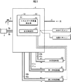
本発明の実施形態について、図1〜図25を参照して説明する。図1を参照して、本実施形態の熱源システムは、熱源機1、台所リモコン2(本発明の熱源機のリモコン装置に相当する)、浴室リモコン4、浴室暖房機60、第1床暖房機61、及び第2床暖房機62を備えている。
An embodiment of the present invention will be described with reference to FIGS. Referring to FIG. 1, a heat source system of the present embodiment includes a
熱源機1には給水管5及び給湯管6が接続され、熱源機1は、給水管5から供給される水を加熱して、給湯設定温度の湯をカラン7等が接続された給湯管6に供給する給湯運転を実行する。
A
また、熱源機1は、暖房往き管60a及び暖房戻り管60bを介して浴室暖房機60と接続され、暖房往き管61a及び暖房戻り管61bを介して第1床暖房機61と接続され、暖房往き管62a及び暖房戻り管62bを介して第2床暖房機62と接続されている。
The
そして、熱源機1は、暖房往き管60a及び暖房戻り管60bを介して温水を循環供給することにより、浴室暖房機60の暖房運転を実行する。同様に、熱源機1は、暖房往き管61a及び暖房戻り管61bを介して温水を循環供給することにより、第1床暖房機61の暖房運転を実行し、暖房往き管62a及び暖房戻り管62bを介して温水を循環供給することにより、第2床暖房機62の暖房運転を実行する。
And the
さらに、熱源機1は、浴槽往き管8a及び浴槽戻り管8bを介して浴槽8と接続され、浴槽往き管8a及び浴槽戻り管8bを介して、浴槽8に湯張り設定量分の湯を供給する自動湯張り運転と、浴槽8内の湯水を浴槽往き管8a及び浴槽戻り管8bを介して循環させながら加熱する追焚き運転と、浴槽8の排水時に少量のお湯を浴槽往き管8a及び浴槽戻り管8bに流して洗浄する配管自動洗浄運転とを実行する。
Furthermore, the
熱源機1は、CPU,メモリ等により構成された電子ユニットであるコントローラ10を備えている。コントローラ10は、メモリに保持された熱源機1の制御用プログラムをCPUで実行することにより、各リモコン2,4の操作に応じて熱源機の作動を制御して、上記給湯運転、暖房運転、自動湯張り運転、追焚き運転、及び配管自動洗浄運転を実行する。
The
また、コントローラ10は、CPUで上記プログラムを実行することにより、熱源機1におけるエネルギー消費量を算出するエネルギー消費量算出部11と、台所リモコン2及び浴室リモコン4の表示部への表示内容を制御する表示制御部12として機能する。
Moreover, the
さらに、コントローラ10は、使用者による台所リモコン2及び浴室リモコン4の意図しない操作によって、台所リモコン2及び浴室リモコン4の表示部が、後述する「メンテナンス1画面」及び「メンテナンス2画面」に切り換わることを回避するための切換制限スイッチ13を備えている。
Furthermore, the
次に、図2(a)を参照して、台所リモコン2は、表示部20、エコシグナル点灯部21、メニュースイッチ22、ダウンスイッチ23、アップスイッチ24、決定スイッチ25、戻るスイッチ26、エネルック(登録商標)スイッチ27、運転スイッチ28、自動スイッチ29、おいだきスイッチ30、及び通話スイッチ31を備えている。
Next, referring to FIG. 2 (a), the kitchen
表示部20には、熱源機1の作動状況や各運転の設定状況等が表示制御部12による制御に応じて表示される。エコシグナル点灯部21には、熱源機1の運転状況に応じて、省エネの程度を示すエコシグナルが表示される。メニュースイッチ22〜戻るスイッチ26は、後述するように、使用者が各運転の開始/停止の指示や運転条件の設定等を行なうためのスイッチである。
On the
エネルック(登録商標)スイッチ27は、後述する「エネルック(登録商標)画面」の表示を指示するためのスイッチである。運転スイッチ28は、熱源機1を各運転の実行が可能な運転状態と、各運転の実行が不能な待機状態とに切替えるためのスイッチである。
The enelook (registered trademark) switch 27 is a switch for instructing display of an “enelook (registered trademark) screen” to be described later. The
自動スイッチ29は、自動湯張り運転の開始と停止を指示するためのスイッチである。おいだきスイッチ30は、追焚き運転の開始と停止を指示するためのスイッチである。通話スイッチ31は、浴室リモコン4とのインターホン通話の開始と停止を指示するためのスイッチである。
The
次に、図2(b)を参照して、浴室リモコン4は、台所リモコン2と同様に、表示部40、エコシグナル点灯部41、メニュースイッチ42、ダウンスイッチ43、アップスイッチ44、決定スイッチ45、戻るスイッチ46、運転スイッチ48、自動スイッチ49、おいだきスイッチ50、通話スイッチ51、及び優先スイッチ52を備えている。
Next, referring to FIG. 2B, the bathroom
浴室リモコン4の各スイッチの機能は、台所リモコン2の同名のスイッチと同じである。優先スイッチ52は、給湯運転における給湯温度を、台所リモコン2による設定温度に優先させて、浴室リモコン4による設定温度とすることを指示するためのスイッチである。
The function of each switch of the bathroom
次に、図3に示したフローチャート及び図4〜図17に示した表示画面の説明図を参照して、台所リモコン2の表示部20の表示態様について説明する。
Next, the display mode of the
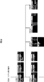
使用者が台所リモコン2の運転スイッチ28を操作して、熱源機1が待機状態から運転状態に切り換わると、表示制御部12は、図4(a)の[0001]の「初期画面」を表示部20に表示する。表示制御部12は、図3のフローチャートにより、熱源機1の作動状況に応じて「初期画面」の表示内容を変更する。
When the user operates the
表示制御部12は、図3のSTEP1で、エネルック(登録商標)マーク(図4(a)では熊のキャラクターマークS、本発明の省エネマークに相当する)が「表示設定」になっているか否かを判断する。そして、エネルック(登録商標)マークが「表示設定」になっているときはSTEP2に進み、STEP3以下の処理によりエネルック(登録商標)を「初期画面」に表示する。一方、エネルック(登録商標)が「非表示設定」になっているときにはSTEP4に分岐し、この場合は「初期画面」にエネルック(登録商標)マークは表示されない。
The
STEP2で、表示制御部12は、熱源機1の各運転(配管自動洗浄運転、自動湯張り運転、浴室暖房運転、第1床暖房運転、第2床暖房運転)の状況を判断する。そして、いずれかの運転が実行中若しくは予約設定中であるときはSTEP20に分岐し、いずれの運転も停止中或いは予約設定がされていないときにはSTEP3に進む。
In
STEP3では、実行中若しくは予約設定がされた運転がないので、表示制御部12は、図4(a)の90gに示したように運転表示エリアL(本発明の所定エリアに相当する)に運転マークの表示をせずに、エネルック(登録商標)マークSを大サイズで表示する。そして、STEP4に進み、熱源機4が運転状態であればSTEP1に戻り、運転状態でなければSTEP5に進んで処理を終了する。
In
STEP20で、表示制御部12は、実行中若しくは予約設定中の運転のマークを、運転表示エリアLに表示する。図4(a)の90aは第2床暖房運転の予約設定がされている場合、90bは配管自動洗浄運転,自動湯張り運転,浴室暖房運転,第1床暖房運転,第2床暖房運転の予約設定がされている場合、90cは自動湯張り運転,浴室暖房運転
,第1床暖房運転,第2床暖房運転の予約設定されている場合の表示例である。
In
また、図4(a)の90dは浴室暖房運転,第1床暖房運転,第2床暖房運転の予約設定されている場合の表示例、90eは第1床暖房運転,第2床暖房運転の予約設定がされている場合、90fは第2床暖房運転の予約設定がされている場合の表示例である。 Also, 90d in FIG. 4 (a) is a display example in the case where a reservation is set for the bathroom heating operation, the first floor heating operation, and the second floor heating operation, and 90e is the first floor heating operation and the second floor heating operation. When the reservation setting is made, 90f is a display example when the reservation setting for the second floor heating operation is made.
続くSTEP21で、表示制御部12は、実行中又は予約設定中の運転の数Nを判断する。そして、運転の数Nが1のときはSTEP3に進み、表示制御部12は、エネルック(登録商標)マークSを大サイズで運転表示エリアLに表示する(図4(a)の90fの状態)。また、運転の数Nが2のときはSTEP30に進み、表示制御部12は、エネルック(登録商標)マークSを大サイズで、運転表示エリアLに表示されている運転のマークの上部に表示する(図4(a)の90eの状態、90eでは第1床暖房運転のマークの上部にエネルック(登録商標)マークSが大サイズで表示されている)。
In
また、運転の数Nが3又は4のときはSTEP31に進み、表示制御部12は、エネルック(登録商標)Sを小サイズで、運転表示エリアLに表示されている運転のマークの上部に表示する(図4(a)の90d,90cの状態、90dでは浴室暖房運転のマークの上部にエネルック(登録商標)マークSが小サイズで表示され、90cでは自動湯張り運転のマークの上部にエネルック(登録商標)マークSが小サイズで表示されている)。また、運転の数Nが5のときはSTEP32に進み、表示制御部12は、エネルック(登録商標)マークSを小サイズで運転表示エリアLの上方に表示する(図4(a)の90bの状態)。
Further, when the number N of driving is 3 or 4, the process proceeds to STEP 31, and the
以上説明したように、表示制御部12は、運転表示エリアLに表示される運転の数Nに応じて、エネルック(登録商標)マークSの位置とサイズを変更して、運転表示エリアLの非表示部又は運転表示エリアLの上方に表示している。そして、これにより、表示部20の非表示部を有効に活用してエネルック(登録商標)マークSの視認性を向上させ、使用者の省エネに関する意識を高めている。
As described above, the
なお、エネルック(登録商標)マークSの表示位置を、使用者が視認する頻度が多いと想定される給湯設定温度(図4(a)では42℃)の表示箇所との間隔を所定値以下とすることにより、使用者がエネルック(登録商標)マークSを視認する機会を増やして、省エネルギーに対する意識をさらに高めることができる。 It should be noted that the interval between the display position of the Eneruk (registered trademark) mark S and the display location of the hot water supply set temperature (42 ° C. in FIG. 4A) that is assumed to be frequently viewed by the user is set to a predetermined value or less. By doing so, the opportunity for a user to visually recognize the EneLook (registered trademark) mark S can be increased, and the awareness of energy saving can be further enhanced.
また、各運転の実行中に故障が検知されたときは、表示制御部12は、図4(b)に示したように、故障の内容を表示する。図4(b)では、浴槽8の栓(図示しない)が外れていることを報知する表示「浴槽の栓を確認してください…」がスクロールして表示されている。また、後述する「リモコン画面」で、シンプル表示が設定されているときには、表示制御部12は、図4(c)示したように、表示部20の表示項目を減少させる。
When a failure is detected during the execution of each operation, the
次に、図5を参照して、表示制御部12は、後述する「エネルック(登録商標)画面」で設定された目標値に対する省エネの達成度合に応じて、エネルック(登録商標)マークの表示態様を、良〜悪の5段階に切替える。また、表示制御部12は、後述する「エネルック(登録商標)画面」で選択されたエネルック(登録商標)マーク(100a〜100fのうちのいずれか)を表示する。なお、表示制御部12により、季節(春,夏,秋,冬)の移り変わりに応じて、エネルック(登録商標)マークを100c〜100fに切替えるようにしてもよい。
Next, referring to FIG. 5, the
次に、図6〜図7を参照して「メンテナンス1画面」について説明する。熱源システムのメンテナンス作業者等が、図4(a)の「初期画面」が表示された状態で、熱源機1のコントローラ10に備えられた切換制限スイッチ13を操作してから所定時間(例えば10分)以内に、ダウンスイッチ23とアップスイッチ24を同時操作すると、表示制御部12は、図6の[3000]の「メンテナンス1画面」を表示部20に表示して、「1.初期設定」〜「5.本体機種設定」の選択を可能とする。
Next, the “
このように、熱源機1に備えられた切換制限スイッチ13の操作を、「メンテナンス1画面」への切換条件に加えることにより、熱源システムの使用者による台所リモコン2の操作によって「メンテナンス1画面」に切り換わり、不適切な設定がなされることを防止している。
Thus, by adding the operation of the
[3000]の「メンテナンス1画面」が表示された状態で、「1.初期設定」が選択されると、表示制御部12は、[3001]画面を表示して、「1.ふろHA」〜「5.メータパルス」の選択を可能とする。また、「2.床暖房メンテ情報」が選択されると、表示制御部12は、[3015]画面を表示して第1床暖房機61(図中床暖房1)、第2床暖房機62(図中床暖房2)、及び浴室暖房機60(図中暖房)の設定値を表示する。
When “1. Initial setting” is selected in a state where “3000” “
また、「3.時刻補正」が選択されると、表示制御部12は、[3019]画面を表示して時刻補正の設定を可能にする。また、「4.本体メンテ設定」が選択されると、表示制御部12は、[3020]画面を表示して浴槽設定の切換を可能にする。
When “3. Time correction” is selected, the
[3001]の「初期画面」が表示された状態で、「1.ふろHA」〜「5.メータパルス」のいずれかが選択されると、表示制御部12は、選択項目に応じて、図7の[3002]画面〜[3012],[3014]画面を表示する。
When any one of “1. Blow HA” to “5. Meter pulse” is selected in a state where the “initial screen” of [3001] is displayed, the
次に、図8を参照して、「メンテナンス2画面」について説明する。熱源システムのメンテナンス作業者等が、図4(a)の「初期画面」が表示された状態で、熱源機1のコントローラ10に備えられた切換制限スイッチ13を操作してから所定時間(例えば10分)以内に、ダウンスイッチ23とアップスイッチ24とメニュースイッチ22を同時操作すると、表示制御部12は、図8の[3022]の「メンテナンス2メニュー」を表示部20に表示する。[3022]画面での選択操作に応じて、例えば[3017],[3028]画面の「故障ガイダンスデモ」、[3025],[3026]画面の「エネルック(登録商標)デモ」が表示される。
Next, the “
次に、図9を参照して、「試運転表示」について説明する。熱源機1が熱源システムの試運転を実行しているときに、表示制御部12は、熱源機1から送信される信号に応じて、[3016]画面を表示する。表示制御部12は、試運転の進行に応じて熱源機から送信される信号に従って、表示内容を図9に示したように順次切替える。
Next, the “trial operation display” will be described with reference to FIG. When the
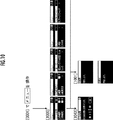
次に、図10〜図15を参照して、「メニュー画面」での表示内容について説明する。図4(a)の[0001]の「初期画面」が表示された状態で、メニュースイッチ22が操作されると、表示制御部12は、図10の[1000]の「メニュー画面」を表示部20に表示する。
Next, display contents on the “menu screen” will be described with reference to FIGS. If the
[1000]の「メニュー画面」では、「1.BGM音量」〜「14.ストップウォッチ」の選択が可能である。「1.BGM音量」が選択されると、表示制御部12は、[1043]画面を表示してBGM音量の変更を可能にする。「2.床暖房1」が選択されると、表示制御部12は、[1001]画面を表示して第1床暖房機61の暖房運転の開始と停止の指示を可能にする。
In “1000” “menu screen”, “1. BGM volume” to “14. stopwatch” can be selected. When “1. BGM volume” is selected, the
[1000]の「メニュー画面」が表示された状態で、「4.床暖房設定」が選択されると、表示制御部12は、図11の[1002]画面を表示して「1.床暖房1」と「2.床暖房2」の選択を可能にする。「1.床暖房1」が選択されると、表示制御部12は、[1003]画面を表示して「1.温度レベル」〜「4.部屋名称の登録」の選択を可能にする。そして、表示制御部12は、選択項目に応じて、[1005]画面、[1006]画面、[1007]画面、[1008]画面等を表示する。
When “4. Floor heating setting” is selected while the “1000” “menu screen” is displayed, the
[1000]の「メニュー画面」が表示された状態で、「6.暖房設定」が選択されると、表示制御部12は、図12の[1010]画面を表示して「1.温度レベル」〜「3.夜間省エネ」の選択を可能にする。「3.夜間省エネ」が選択されると、表示制御部12は、[1015],[1016]画面を表示して夜間省エネのレベルと時間帯の設定を可能にする。
When “6. Heating setting” is selected while the “1000” “menu screen” is displayed, the
[1000]の「メニュー画面」の選択項目からは省略されているが、「浴室暖房設定」が選択されると、表示制御部12は、図13(a)の[1017]画面を表示して、[1018]画面による予約設定/解除と[1019]画面による予約時刻の変更を可能にする。
Although omitted from the selection item of “1000 screen” of “1000”, when “bathroom heating setting” is selected, the
[1000]の「メニュー画面」が表示された状態で、「8.エコシグナル設定」が選択されると、表示制御部12は、図13(a)の[1030]画面を表示して湯量の設定を可能とする。
When “8. Eco signal setting” is selected while the “1000” “menu screen” is displayed, the
[1000]の「メニュー画面」が表示された状態で、「9.ふろ」が選択されると、表示制御部12は、図13(b)の[1032]画面を表示して「1.ふろ予約」〜「6.ふろ保温時間」の選択を可能とする。表示制御部12は、例えば「3.ふろ温度」が選択されると[1035]画面を表示し、「4.ふろ水位」が選択されると[1036]画面を表示し、「6.ふろ保温時間」が選択されると[1041]画面を表示する。
When “9. bath” is selected while the “menu screen” of [1000] is displayed, the
[1000]の「メニュー画面」が表示された状態で、「10.リモコン」が選択されると、表示制御部12は、図14の[1042]画面を表示して「1.リモコン音声音量」〜「9.コントラスト」の設定を可能とする。表示制御部12は、例えば「1.リモコン音声音量」が選択されると[1044]画面を表示し、「2.シンプル表示」が選択されると[1048]画面を表示し、「5.誕生日設定」が選択されると[1052],[1053]画面を表示し、「7.画面色反転」が選択されると[1055]画面を表示し、「8.明るさ」が選択されると[1056]画面を表示する。
When “10. Remote control” is selected while the “menu screen” of [1000] is displayed, the
[1000]の「メニュー画面」が表示された状態で、「12.その他」が選択されると、表示制御部12は、図15の[1058]画面を表示して、静音運転(暖房時)の設定を可能とする。
When “12. Other” is selected while the “menu screen” of [1000] is displayed, the
[1000]の「メニュー画面」が表示された状態で、「14.ストップウォッチ」が選択されると、表示制御部12は、図15の[1060]画面を表示して、ストップウォッチのスタート/ストップ/リセットの指示を可能とする。
When “14. Stopwatch” is selected while the “menu screen” of [1000] is displayed, the
次に、図4(a)の[0001]の初期画面が表示された状態で、エネルック(登録商標)スイッチ27が操作されると、表示制御部12は、図16の[2000]の「エネルック(登録商標)画面」を表示して、「1.まとめてLIVE」〜「9.エネルック(登録商標)設定」の選択を可能とする。
Next, when the enelook (registered trademark) switch 27 is operated in a state where the initial screen of [0001] in FIG. 4A is displayed, the
[2000]の「エネルック(登録商標)画面」で「1.まとめてLIVE」が選択されると、表示制御部12は、[2001]画面を表示し、「2.まとめてルック」が選択されると[2002]画面を表示する。また、表示制御部12は、「3.環境貢献]が選択されると、[2003],[2145]画面を表示する。
When “1. Collectively LIVE” is selected in the “EneLook (registered trademark) screen” of [2000], the
[2000]の「エネルック(登録商標)画面」で「4.CO2」が選択されると、表示制御部12は、[2004]画面を表示して、[2005]〜[2007]画面による月単位でのCO2の排出量と、[2008]〜[2010]画面による週単位でのCO2の排出量と、[2011]〜[2013]画面による日単位でのCO2の排出量とを、切替えて表示する。
When “4.CO 2 ” is selected in the “EneLook (registered trademark) screen” of [2000], the
[2000]の「エネルック(登録商標)画面」で「9.エネルック(登録商標)設定」が選択されると、表示制御部12は、図17の[2112]の「エネルック(登録商標)設定画面」を表示して、「1.エネLIVE設定」〜「8.設定リセット」の選択を可能とする。
When “9. Enerook (registered trademark) setting” is selected in the “EneLook (registered trademark) screen” of [2000], the
[2112]の「エネルック(登録商標)画面」で「1.エネLIVE設定」が選択されると、表示制御部12は、[2113]画面を表示して、給湯器のガス使用量、お湯使用量、電気使用量の表示/非表示の設定を可能とする。
When “1. ENE LIVE setting” is selected in the “EneLook (registered trademark) screen” in [2112], the
[2112]の「エネルック(登録商標)画面」で「2.目標」が選択されると、表示制御部12は、[2114]画面を表示して、現在のガス、お湯、電気の目標値を表示する。また、表示制御部12は、[2117],[2118]画面により、CO2排出量等の目標値の選択を可能とする。
When “2. Target” is selected in the “EneLook (registered trademark) screen” in [2112], the
[2112]の「エネルック(登録商標)画面」で「3.単価」が選択されると、表示制御部12は[2126]画面を表示して、ガス,水道,電気の現在の単価を表示すると共に、各単価の設定を可能とする。
When “3. Unit price” is selected on the “EneLook (registered trademark) screen” of [2112], the
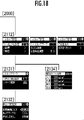
[2112]の「エネルック(登録商標)画面」で「4.エネルック(登録商標)マーク」が選択されると、表示制御部12は図18の[2131],[2132]画面を表示して、エネルック(登録商標)マークの表示/非表示の設定と、表示するエネルック(登録商標)マークの種類の選択を可能にする。
When “4. Enerook (registered trademark) mark” is selected in the “EneLook (registered trademark) screen” of [2112], the
[2112]の「エネルック(登録商標)画面」で「5.CO2係数」が選択されると、表示制御部12は[2134]画面を表示して、ガス,水道,電気,石油の現在のCO2係数を表示すると共に、各係数の設定を可能にする。
When “5. CO 2 coefficient” is selected in the “EneLook (registered trademark) screen” in [2112], the
次に、図19〜図25に示した表示画面の説明図を参照して、浴室リモコン4の表示部40の表示態様について説明する。
Next, the display mode of the
使用者が浴室リモコン4の運転スイッチ48を操作して、熱源機1が待機状態から運転状態に切り換わると、表示制御部12は、図19の[4001]の「初期画面」を表示部40に表示する。表示制御部12は、熱源機1の作動状況に応じて「初期画面」の表示内容を変更する。
When the user operates the
表示制御部12は、熱源機1の運転(配管自動洗浄運転、自動湯張り運転、浴室暖房運転)の状況を判断する。そして、実行中若しくは予約設定がされている運転を、表示部40に表示する。表示制御部12は、風呂洗浄運転と自動湯張り運転と浴室暖房運転の全てが運転若しくは予約設定がされているときは、130aに示したように、表示部40の運転表示エリアMに「洗浄」(風呂洗浄を示す),「ふろ」(自動湯張りを示す),「浴暖」(浴室暖房を示す)の各マークを表示する。
The
また、表示制御部12は、自動湯張り運転と浴室暖房運転の実行若しくは予約設定がされているときは、130bに示したように、表示部40の運転表示エリアMに「ふろ」,「浴暖」のマークを表示し、浴室暖房運転のみの実行若しくは予約設定がされているときは、130cに示したように、表示部40の運転表示エリアMに「浴暖」マークを表示する。また、表示制御部12は、実行又は予約設定がされている運転がないときには、130dに示したように、表示部40の運転表示エリアMへのマークの表示は行わない。
When the automatic filling operation and bathroom heating operation are executed or reserved, the
なお、120に示したように、表示制御部12は、実行中の運転のマークについては時計形状を非表示とし、予約設定中の運転のマークについては時計形状を全表示する。さらに、表示制御部12は、予約運転中の運転のマークについては、予約運転の残り時間に応じて時計形状を全表示から非表示まで段階的に変化させる。
As indicated by 120, the
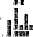
[4001]の「初期画面」が表示された状態でメニュースイッチ42が操作されると、表示制御部12は、表示部40を[5000]の「メニュー画面」に切替えて、「1.BGM音量」〜「15.その他」の選択を可能にする。
When the
また、表示制御部12は、「初期画面」が表示された状態で、浴室リモコン4の操作がなされない状況が所定時間以上継続したときに、[4005]の「スクリーンセーバー画面」に移行する。「スクリーンセーバー画面」では、表示制御部12は、125に示したように、1行表示を右から左にスクロールさせつつ、上から下に向けて繰り返しシフトさせて表示する。
The
熱源システムのメンテナンス作業者等が、[4001]の「初期画面」が表示された状態で、熱源機1のコントローラ10に備えられた切換制限スイッチ13を操作してから所定時間(例えば10分)以内に、ダウンスイッチ43とアップスイッチ44を同時操作すると、表示制御部12は、図20(a)の[6000]の「メンテナンス1画面」を表示して、「1.初期設定」〜「3.本体機種設定」の選択を可能にする。表示制御部12は、「1.初期設定」が選択されると[6001],[6002]画面を表示し、「2.本体メンテ設定」が選択されると[6003]画面を表示する。
A predetermined time (for example, 10 minutes) after a maintenance worker or the like of the heat source system operates the
熱源システムのメンテナンス作業者等が、[4001]の「初期画面」が表示された状態で、熱源機1のコントローラ10に備えられた切換制限スイッチ13を操作してから所定時間(例えば10分)以内に、ダウンスイッチ43とアップスイッチ44とメニュースイッチ42を同時操作したときに、表示制御部12は、図20(b)の[6005]の「メンテナンス2画面」を表示して、「1.故障ガイダンスデモ」と「2.Ecoシグナルデモ」の選択を可能にする。表示制御部12は、「1.故障ガイダンスデモ」が選択されると[6006],[6008]画面を表示する。
A predetermined time (for example, 10 minutes) after a maintenance worker or the like of the heat source system operates the
次に、図19に示した[5000]の「メニュー画面」が表示された状態で、「5.ヒーリングミュージック」が選択されると、表示制御部12は、図21の[5038]画面を表示して、ヒーリングミュージックの停止と選択を可能にする。また、「1.BGM音量」が選択されると、表示制御部12は、図21の[5027]画面を表示して、BGM音量の設定を可能にする。
Next, when “5. Healing music” is selected while the “5000” “menu screen” shown in FIG. 19 is displayed, the
[5000]の「メニュー画面」が表示された状態で、「12.エネLIVE設定」が選択されると、表示制御部12は、図21の[5004]画面を表示して、ガス,お湯,電気の使用量を初期画面に表示するか否かの設定を可能にする。また、表示制御部12は、各使用量について、合計値と現在値のいずれを表示するかの設定を可能にする。
When “12. Energy LIVE setting” is selected while the “5000” “menu screen” is displayed, the
[5000]の「メニュー画面」が表示された状態で、「13.選べるEcoモード」が選択されると、表示制御部12は、図22の[5005]画面を表示して、[5006]画面によるEcoモード運転の設定と、[5007],[5008]画面によるEcoモード選択の設定を可能にする。
When “13. Selectable Eco mode” is selected while the “5000” “menu screen” is displayed, the
[5000]の「メニュー画面」が表示された状態で、「14.Ecoシグナル設定」が選択されると、表示制御部12は、図22の[5015]画面を表示して、Ecoシグナルの解除及び点灯条件の設定を可能にする。
When “14. Eco signal setting” is selected while the “5000” “menu screen” is displayed, the
[5000]の「メニュー画面」が表示された状態で、「9.ふろ」が選択されると、表示制御部12は、図23の[5015]画面を表示して「1.ふろ温度」〜「3.半身浴」の選択を可能にする。そして、表示制御部12は、「1.ふろ温度」が選択されたときは[5018]画面を表示し、「2.ふろ水位」が選択されたときは[5019]画面を表示し、「3.半身浴」が選択されたときは[5020],[5021],[5023]画面を表示して、各表示項目の設定を可能にする。
If “9. bath” is selected while the “menu screen” of “5000” is displayed, the
[5000]の「メニュー画面」が表示された状態で、「6.浴室暖房」が選択されると、表示制御部12は、図24の[5025]画面を表示して浴室暖房運転の開始と停止の指示を可能にする。
When “6. Bathroom heating” is selected while the “5000” “menu screen” is displayed, the
[5000]の「メニュー画面」が表示された状態で、「11.まとめてLIVE」が選択されると、表示制御部12は、図24の[5040]画面を表示して、ガス,お湯,電気又は、ガス,お湯の使用量の現在値を表示する。
When “11. Collective LIVE” is selected while the “5000” “menu screen” is displayed, the
[5000]の「メニュー画面」が表示された状態で、「10.リモコン」が選択されると、表示制御部12は、図24の[5026]画面を表示して、「1.リモコン音声音量」〜「4.明るさ」の選択を可能にする。表示制御部12は、「1.リモコン音声音量」が選択されると[5028],[5029]画面を表示し、「2.故障ガイダンス」が選択されると[5032]画面を表示し、「4.明るさ」が選択されると[5034]画面を表示する。
When “10. Remote control” is selected while the “5000” “menu screen” is displayed, the
[5000]の「メニュー画面」が表示された状態で、「15.その他」が選択されると、表示制御部12は、図25の[5035]画面を表示して静音運転を行なうか否かの設定を可能にする。
When “15. Others” is selected while the “5000” “menu screen” is displayed, the
[5000]の「メニュー画面」が表示された状態で、「8.ストップウォッチ」が選択されると、表示制御部12は、図25の[5037]画面を表示して、ストップウォッチのスタート/ストップ/リセットの指示を可能にする。
When “8. Stopwatch” is selected while the “5000” “menu screen” is displayed, the
なお、本実施形態では、図4(a)に示したように、省エネ表示(エネルック(登録商標)マーク)の大きさ(大・小)を、運転状況の表示エリアLの空き領域の大きさに応じて変更したが、省エネ表示の表示箇所はこれに限らず、表示部の適当な空き領域を選択して、省エネ表示の表示箇所とサイズを決定すればよい。 In the present embodiment, as shown in FIG. 4A, the size (large / small) of the energy saving display (EneLook (registered trademark) mark) is set to the size of the empty area of the operation status display area L. However, the display location of the energy saving display is not limited to this, and an appropriate empty area of the display unit may be selected to determine the display location and size of the energy saving display.
また、本実施形態では、省エネ表示を給湯設定温度の表示箇所の近傍に表示させたが、表示部の表示態様によっては、給湯設定温度の表示箇所からある程度離れた箇所に省エネ表示を表示させる場合にも、本発明の効果を得ることができる。 In the present embodiment, the energy saving display is displayed in the vicinity of the display location of the hot water supply set temperature. However, depending on the display mode of the display unit, the energy saving display may be displayed at a location some distance from the display location of the hot water supply set temperature. In addition, the effects of the present invention can be obtained.
1…熱源機、2…台所リモコン、4…浴室リモコン、10…コントローラ、11…エネルギー消費量算出部、12…表示制御部、20,40…表示部、22,42…メニュースイッチ、23,43…ダウンスイッチ、24,44…アップスイッチ、25,45…決定スイッチ、26,45…設定スイッチ、27…エネルック(登録商標)スイッチ、60…浴室暖房機、61…第1床暖房機、62…第2床暖房機、L…運転状況の表示エリア、S…エネルック(登録商標)マーク。
DESCRIPTION OF
Claims (4)
表示部と、
前記熱源機におけるエネルギー消費量を算出するエネルギー消費量算出部と、
該エネルギー消費量算出部により算出されたエネルギー消費量に基づいて、省エネルギーを促すための省エネマークを、前記表示部に表示させる表示制御部とを備えた熱源機のリモコン装置において、
前記表示制御部は、前記表示部における前記省エネマーク以外の表示状況に応じて、前記省エネマークの表示位置を変更することを特徴とする熱源機のリモコン装置。 An operation unit for remotely operating the heat source device;
A display unit;
An energy consumption calculating unit for calculating energy consumption in the heat source unit;
In a remote control device of a heat source machine comprising a display control unit for displaying an energy saving mark for promoting energy saving on the display unit based on the energy consumption calculated by the energy consumption calculating unit,
The remote control device for a heat source apparatus, wherein the display control unit changes a display position of the energy saving mark according to a display state other than the energy saving mark on the display unit.
前記表示制御部は、前記表示部における前記省エネマーク以外の表示状況に応じて、前記省エネマークのサイズを変更することを特徴とする熱源機のリモコン装置。 In the remote control device of the heat source machine according to claim 1,
The remote control device for a heat source device, wherein the display control unit changes a size of the energy saving mark according to a display state other than the energy saving mark on the display unit.
前記熱源機は給湯機能を有して、前記表示部には給湯設定温度が表示され、
前記表示制御部は、前記給湯設定温度の表示との間隔を所定値以下として、前記省エネマークを表示することを特徴とする熱源機のリモコン装置。 In the remote control device of the heat source machine according to claim 1 or 2,
The heat source unit has a hot water supply function, and the display unit displays a hot water supply set temperature.
The display control unit displays the energy saving mark by setting an interval from the display of the hot water supply set temperature to a predetermined value or less, and a remote control device for a heat source machine.
前記熱源機は複数種類の運転を行なう機能を有し、
前記表示制御部は、前記複数種類の運転のうち、実行中又は予約設定中である運転のマークを、前記表示部の所定エリアに表示し、該所定エリアに表示されている運転のマークの個数が減少するに従って、前記省エネマークのサイズを拡大して前記所定エリアに表示することを特徴とする熱源機のリモコン装置。 In the remote control device of the heat source unit according to any one of claims 1 to 3,
The heat source machine has a function of performing a plurality of types of operation,
The display control unit displays, in a predetermined area of the display unit, an operation mark that is being executed or reserved among the plurality of types of operation, and the number of operation marks displayed in the predetermined area A remote control device for a heat source device, wherein the size of the energy saving mark is enlarged and displayed in the predetermined area as the value decreases.
Priority Applications (1)
| Application Number | Priority Date | Filing Date | Title |
|---|---|---|---|
| JP2010260598A JP2012112559A (en) | 2010-11-22 | 2010-11-22 | Remote controller of heat source system |
Applications Claiming Priority (1)
| Application Number | Priority Date | Filing Date | Title |
|---|---|---|---|
| JP2010260598A JP2012112559A (en) | 2010-11-22 | 2010-11-22 | Remote controller of heat source system |
Publications (1)
| Publication Number | Publication Date |
|---|---|
| JP2012112559A true JP2012112559A (en) | 2012-06-14 |
Family
ID=46496978
Family Applications (1)
| Application Number | Title | Priority Date | Filing Date |
|---|---|---|---|
| JP2010260598A Pending JP2012112559A (en) | 2010-11-22 | 2010-11-22 | Remote controller of heat source system |
Country Status (1)
| Country | Link |
|---|---|
| JP (1) | JP2012112559A (en) |
Cited By (4)
| Publication number | Priority date | Publication date | Assignee | Title |
|---|---|---|---|---|
| JP2015068589A (en) * | 2013-09-30 | 2015-04-13 | 株式会社デンソー | Remote control for water heater |
| JP2015068530A (en) * | 2013-09-27 | 2015-04-13 | 株式会社ノーリツ | Resource usage display device and remote controller for water heater |
| JP2019056494A (en) * | 2017-09-19 | 2019-04-11 | 株式会社コロナ | Temperature adjustment system |
| JP2022103876A (en) * | 2020-12-28 | 2022-07-08 | 株式会社Lixil | Remote operation system |
-
2010
- 2010-11-22 JP JP2010260598A patent/JP2012112559A/en active Pending
Cited By (5)
| Publication number | Priority date | Publication date | Assignee | Title |
|---|---|---|---|---|
| JP2015068530A (en) * | 2013-09-27 | 2015-04-13 | 株式会社ノーリツ | Resource usage display device and remote controller for water heater |
| JP2015068589A (en) * | 2013-09-30 | 2015-04-13 | 株式会社デンソー | Remote control for water heater |
| JP2019056494A (en) * | 2017-09-19 | 2019-04-11 | 株式会社コロナ | Temperature adjustment system |
| JP2022103876A (en) * | 2020-12-28 | 2022-07-08 | 株式会社Lixil | Remote operation system |
| JP7394744B2 (en) | 2020-12-28 | 2023-12-08 | 株式会社Lixil | remote control system |
Similar Documents
| Publication | Publication Date | Title |
|---|---|---|
| JP5504206B2 (en) | Game machine | |
| EP2662485A2 (en) | Laundry treating apparatus and remote controller | |
| JP2012112559A (en) | Remote controller of heat source system | |
| JP2022075702A (en) | Level display method, level display system, program, level display device, remote control device, and hot water supply system | |
| JP2000274778A (en) | Energy management apparatus | |
| JP6014568B2 (en) | Control device, control method, control system, control program, and notification device | |
| CN105958640A (en) | Residential user requirement response system | |
| CN204650156U (en) | The display control unit of cooking apparatus and cooking apparatus | |
| KR20120080082A (en) | Laundry handling apparatus | |
| JP2014158922A (en) | Game machine | |
| JP2007157377A (en) | Induction heating device | |
| JP2007136231A (en) | Game machine | |
| JP2006255063A (en) | Washing machine and its program | |
| JP5340980B2 (en) | Remote control device for water heater | |
| WO2013094319A1 (en) | Power management apparatus | |
| JP2013201864A (en) | Communication apparatus and home appliance control method and program | |
| JP2015181816A5 (en) | ||
| CN105180458B (en) | The rural area particular market type water heater and its control method shown with hot water amount | |
| CN109893066B (en) | Method for displaying energy consumption proportion of dish-washing machine and dish-washing machine with method | |
| JP2016220257A (en) | Control device, control method, control system, control program, and notification apparatus | |
| JP5465026B2 (en) | Remote control device | |
| JP5899404B2 (en) | Induction heating cooking equipment | |
| JP2004286319A (en) | Power-saving remote controller | |
| JP2015181819A5 (en) | ||
| JP5963664B2 (en) | Energy saving plan support information creation system and building |