JP2012111421A - Actuator - Google Patents
Actuator Download PDFInfo
- Publication number
- JP2012111421A JP2012111421A JP2010263828A JP2010263828A JP2012111421A JP 2012111421 A JP2012111421 A JP 2012111421A JP 2010263828 A JP2010263828 A JP 2010263828A JP 2010263828 A JP2010263828 A JP 2010263828A JP 2012111421 A JP2012111421 A JP 2012111421A
- Authority
- JP
- Japan
- Prior art keywords
- motor
- case
- rotating shaft
- fixing means
- axial direction
- Prior art date
- Legal status (The legal status is an assumption and is not a legal conclusion. Google has not performed a legal analysis and makes no representation as to the accuracy of the status listed.)
- Pending
Links
Images


Abstract
Description
本発明は、アクチュエータに関し、特に、自動車用空調装置内に取り付けられた各ドアを開閉制御するアクチュエータに関する。 The present invention relates to an actuator, and more particularly to an actuator that controls opening and closing of each door mounted in an automotive air conditioner.
例えば、特許文献1には、図9に示すように、下ケース101のモータ収容凹部にモータ102を載置し、その回転軸の先端(一端)103にウォーム104を固着してなるアクチュエータが開示されている。このウォーム104は第1減速ギヤ105に歯合され、第1減速ギヤ105に歯合する第2減速ギヤ106は出力ギヤ(出力軸)107に歯合されている。そして、回転軸の先端103側には、回転軸の軸方向の移動を制限するスラスト受部108が下ケース101に設けられ、回転軸の先端103とスラスト受部108との間には、隙間が設けられている。
For example,
この隙間は、例えば、回転軸の長さ方向の寸法公差や、下ケースにおけるスラスト受部の位置の寸法公差や、下ケースとモータの組立の寸法公差が最大になった場合であっても、回転軸がスラスト受部により押圧されないように設定されている。すなわち、上述の部品や組立の寸法公差が最大の場合であっても回転軸の先端はスラスト受部と隙間を持つように設定される。このようにすると回転軸の先端はスラスト受部により押圧されず、モータ回転時、回転軸の他端を受けるモータ内のスラストプレートの耐久性の低下が低減できる。 This gap is, for example, when the dimensional tolerance in the longitudinal direction of the rotating shaft, the dimensional tolerance of the position of the thrust receiving portion in the lower case, or the dimensional tolerance of the assembly of the lower case and the motor is maximized. The rotation shaft is set so as not to be pressed by the thrust receiving portion. That is, the tip of the rotating shaft is set so as to have a gap with the thrust receiving portion even when the dimensional tolerance of the above-described parts or assembly is maximum. If it does in this way, the tip of a rotating shaft will not be pressed by a thrust receiving part, and the fall of the endurance of the thrust plate in the motor which receives the other end of a rotating shaft at the time of motor rotation can be reduced.
しかしながら、上述の部品や組立の寸法公差によっては隙間が大きくなり、ウォームがモータから突出する方向に回転し始める際、回転軸がスラスト移動して、回転軸の先端がスラスト受部に衝突することによって大きな打音が発生してしまう。また、回転軸がモータから突出する方向に回転中に出力軸の負荷がなくなったり、あるいは、回転軸が逆回転したりすると、回転軸がスラスト移動して、回転軸の他端がモータ内のスラストプレートに衝突することによっても大きな打音が発生してしまう。
そこで、上述の部品や組立の寸法公差の精度を高め回転軸の先端とスラスト受部の隙間を小さく設定すれば打音は低減できるが、部品の製造コストが高くなってしまう。
However, depending on the dimensional tolerances of the parts and assemblies described above, the gap becomes large, and when the worm starts to rotate in the direction protruding from the motor, the rotating shaft thrusts and the tip of the rotating shaft collides with the thrust receiving part. Will produce a loud sound. Also, if the load on the output shaft disappears while the rotating shaft is rotating in the direction protruding from the motor, or if the rotating shaft rotates in the reverse direction, the rotating shaft is thrust and the other end of the rotating shaft is moved into the motor. A large hitting sound is also generated by collision with the thrust plate.
Therefore, if the accuracy of the dimensional tolerance of the above-mentioned parts and assembly is increased and the clearance between the tip of the rotating shaft and the thrust receiving part is set small, the hitting sound can be reduced, but the manufacturing cost of the parts becomes high.
そこで、本発明は、部品や組立の寸法公差の精度を高めることなく打音の低減ができるアクチュエータを提供する。 Therefore, the present invention provides an actuator that can reduce the hitting sound without increasing the accuracy of dimensional tolerances of parts and assemblies.
上記の目的を達成すべく成された本発明の請求項1のアクチュエータは、
ケースと、前記ケース内に設けられウォームが回転軸に固着されたモータと、前記ウォームと歯合するギヤとを備えるアクチュエータであって、
前記ケース内には、前記モータの回転軸の先端側に、前記回転軸のスラスト移動を制限するスラスト受部が配置され、
前記ケースと前記モータにはそれぞれ、前記モータを前記回転軸の軸方向における位置を調整して固定できる固定手段が設けられ、
前記固定手段は、前記モータに設けられ前記回転軸の軸方向に形成された突条形状もしくは溝形状からなるモータ側固定手段と、前記モータ側固定手段に嵌合するものであって前記ケース内に設けられ前記回転軸の軸方向に形成された溝形状もしくは突条形状からなるケース側固定手段とからなることを特徴とする。
The actuator of
An actuator comprising a case, a motor provided in the case and having a worm fixed to a rotating shaft, and a gear meshing with the worm,
In the case, a thrust receiving portion for restricting thrust movement of the rotary shaft is disposed on the tip side of the rotary shaft of the motor,
Each of the case and the motor is provided with a fixing means capable of fixing the motor by adjusting the position in the axial direction of the rotating shaft,
The fixing means includes a motor-side fixing means that is provided on the motor and has a ridge shape or a groove shape formed in the axial direction of the rotating shaft, and is fitted into the motor-side fixing means. And a case side fixing means having a groove shape or a ridge shape formed in the axial direction of the rotating shaft.
本発明の請求項2のアクチュエータは、請求項1に記載のアクチュエータにおいて、
前記モータ側固定手段は、前記モータのモータケースに設けられることを特徴とする。
The actuator according to claim 2 of the present invention is the actuator according to
The motor side fixing means is provided in a motor case of the motor.
本発明によれば、ケースとモータにはそれぞれ、モータを回転軸の軸方向における位置を調整して固定できる固定手段が設けられるため、部品や組立の寸法公差の精度を高めることなく回転軸のスラスト移動を抑えることができ打音の低減ができる。 According to the present invention, the case and the motor are each provided with fixing means that can fix the motor by adjusting the position of the rotating shaft in the axial direction. Thrust movement can be suppressed and the hitting sound can be reduced.
以下、図面を参照して本発明の一実施形態に係るアクチュエータ1について説明する。
Hereinafter, an
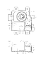
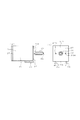
図1は、本発明の一実施形態に係るアクチュエータ1の完成品の平面図である。図2(a)は、本発明の一実施形態に係るアクチュエータの上ケースを除いた平面図であり、図2(b)は、図2(a)の切断線A−Aの断面図である。図3(a)は、本発明の一実施形態に係る下ケースの平面図であり、図3(b)は、図3(a)の切断線B−Bの断面図である。図4(a)は、本発明の一実施形態に係るモータの正面図であり、図4(b)は、図4(a)の側面図である。
本実施形態のアクチュエータ1は、図2に示すように、ケース10、モータ20、ギヤ30を有する。
FIG. 1 is a plan view of a finished product of an
As shown in FIG. 2, the
ケース10は、モータ20及びギヤ30を収容するためのものである。ケース10の具体的な構成例として、樹脂材料の上ケース11と下ケース12に有する収容凹部の開口が対向するように組み付けられ、上ケース11と下ケース12との間に形成される収容凹部には、モータ20及びギヤ30が収容される。
The
そして、下ケース12内には、モータ20の回転軸の先端22に対向するようにスラスト受部13が設けられている。このスラスト受部13は、平面を有する受板であり下ケース12と一体に成形され、回転軸21がモータ20から突出方向に移動する際、回転軸21のスラスト移動の制限をする。
A
モータ20は、ブラシ付モータから構成され、有底円筒状のモータケース24と、モータケース24の開口端を塞ぐモータケース蓋25と、モータケース24とモータケース蓋25にそれぞれ設けられた図示しない軸受と、軸受に回転支持された回転軸21と、回転軸21と一体に回転する図示しないロータを有する。このモータ20は、ブラシレスモータであってもよい。
The
この回転軸21は、モータケースの底部24Aから突出し、この突出した回転軸21には、ウォーム26が固着されている。
本実施形態では、図2に示すように、回転軸の先端(一端)22がウォーム26から突出する。そして、回転軸21の基端(他端)は、モータケース蓋25内に設けられた図示しないスラストプレートに当接され回転支持されている。
The rotating
In the present embodiment, as shown in FIG. 2, the tip (one end) 22 of the rotating shaft protrudes from the
モータ20は、通常、各部品の寸法精度や組立寸法精度にバラツキがあるため、モータケース24の軸受とロータとの間には軸方向(矢印X方向)にクリアランス(スラスト方向の遊び量)が設けられ、回転軸21は、モータケース24から突出する方向に遊び量だけスラスト移動できる。
Since the
このモータ20は、図4に示すように、断面略L字形状のモータ保持部27を介して下ケース12に取り付けられる。この保持部27は、樹脂材料あるいは金属材料で形成される。モータ保持部27の立上部27Aには、モータ20の回転軸21が通過できる図示しない貫通孔が設けられ、回転軸21を貫通孔に通過させた後、モータケースの底部24Aがモータ保持部27の立上部27Aにネジ27A1で固定される。
As shown in FIG. 4, the
そして、下ケース12とモータ20にはそれぞれ、モータ20を回転軸21の軸方向(矢印X方向)における位置を調整して固定できる固定手段が設けられている。
The
この固定手段は、モータ20に設けられ回転軸21の軸方向に形成された突条形状23からなるモータ側固定手段と、モータ側固定手段に嵌合するものであって下ケース12内に設けられ回転軸21の軸方向に形成された溝形状14からなるケース側固定手段とからなる。
The fixing means is provided in the
本実施形態では、突条形状23は、モータ保持部27のベース部27Bの底面にモータ20の回転軸方向に並んで2つ設けられ、この突条形状23に嵌合する溝形状14は、下ケース12内に回転軸の軸方向に並んで2つ設けられている。この溝形状14は、スラスト受部13の板面と略直角方向に形成され、モータ20を下ケース12に固定すると、回転軸21の軸方向は、スラスト受部13の板面と略直交方向になる。
In the present embodiment, two ridge shapes 23 are provided on the bottom surface of the
この突条形状23の幅H1は、下ケース12内に有する溝形状14の幅H2と略同一に形成され、モータ20の突条形状23が下ケース12内の溝形状14に嵌合すると、モータ20は下ケース12に対して固定(固着)できる。
The width H1 of the
上述の説明では、モータ側固定手段は突条形状23であり、ケース側固定手段は溝形状14であるが、モータ側固定手段が溝形状であり、ケース側固定手段が突条形状であってもよい。
また、上述の説明では、突条形状23と溝形状14はそれぞれ2つ設けられたが、突条形状23は、1つあるいは3つ以上設けられ、この突条形状23に嵌合する溝形状14が、下ケース12内に1つあるいは3つ以上設けられてもよい。
In the above description, the motor side fixing means has the
In the above description, two ridge shapes 23 and two
また、上述の説明では、スラスト受部の板面は回転軸の軸方向と略直交方向に形成されているが、回転軸は、スラスト受部に当接して回転軸の移動が制限できればよく、スラスト受部の板面は、回転軸の軸方向に対し傾きがあって設けられてもよいし、スラスト受部は、回転軸の先端が当接する部分が突起形状を有するものであってもよい。 Further, in the above description, the plate surface of the thrust receiving portion is formed in a direction substantially orthogonal to the axial direction of the rotating shaft, but the rotating shaft only needs to abut against the thrust receiving portion to limit the movement of the rotating shaft, The plate surface of the thrust receiving portion may be provided with an inclination with respect to the axial direction of the rotating shaft, and the thrust receiving portion may have a protruding shape at the portion where the tip of the rotating shaft contacts. .
ギヤ30は、複数のギヤから構成され、第1ギヤ31、第2ギヤ32、出力ギヤ(出力軸)33を有する。このギヤ30は、それぞれ上下ケースにより回転自在に軸支される。そして、第1ギヤ31は、モータ20の回転軸21のウォーム26と歯合される。第2ギヤ32は、第1ギヤ31と歯合される。出力軸33は、第2ギヤ32と歯合される。そして、出力軸33は、自動車用空調装置内に取り付けられた各ドアに係合され、モータ20の回転軸21の回転力が伝達されると、各ドアの開閉制御ができる。
The
次に、このアクチュエータ1の組立方法について説明する。
モータ20には、モータ保持部27が取り付けられる。そして、モータ20の回転軸の先端22が下ケース12内のスラスト受部13に対向するようにモータ20が下ケース12に配置される。
Next, a method for assembling the
A
本実施形態では、下ケース12とモータ20にはそれぞれ、モータ20を回転軸21の軸方向における位置を調整して固定できる固定手段が設けられ、この固定手段は、モータ20に設けられ回転軸21の軸方向に形成された突条形状23からなるモータ側固定手段と、モータ側固定手段に嵌合するものであって下ケース12内に設けられ回転軸21の軸方向に形成された溝形状14からなるケース側固定手段とからなる。
In the present embodiment, the
そして、このモータ20は、下ケース12に組み付けられる際、回転軸の先端22とスラスト受部13が近接するように軸方向に位置調整され、モータ20の突条形状23は、下ケース12の収容凹部の開口方向(矢印Y方向)に沿って下ケース12の溝形状14に圧入され嵌合される。
When the
より具体的には、モータ20を下ケース12に組み付ける際に、例えば、回転軸の先端22とスラスト受部13との間に隙間調整用の図示しないスラストゲージを挟み、回転軸の先端22をスラストゲージに押接しながらモータ20を下ケース12に固定後、スラストゲージを取り外し、回転軸の先端22とスラスト受部13を所定の隙間に設定された状態で、モータ20の突条形状23と下ケース12の溝形状14が嵌合される。
More specifically, when assembling the
その後、回転軸21のウォーム26に歯合するように第1ギヤ31が下ケース12に設けられ、次に第2ギヤ32、出力軸33がそれぞれ下ケース12に設けられ、上ケース11が下ケース12に被せられる。
Thereafter, the
以上のように、実施形態のアクチュエータ1は、ケース10と、ケース10内に設けられウォーム26が回転軸21に固着されたモータ20と、ウォーム26と歯合するギヤ30とを備えるアクチュエータ1である。このケース10内には、モータ20の回転軸の先端22側に、回転軸21のスラスト移動を制限するスラスト受部13が配置され、ケース10とモータ20にはそれぞれ、モータ20を回転軸21の軸方向における位置を調整して固定できる固定手段が設けられる。この固定手段は、モータ20に設けられ回転軸21の軸方向に形成された突条形状もしくは溝形状からなるモータ側固定手段と、モータ側固定手段に嵌合するものであってケース10内に設けられ回転軸21の軸方向に形成された溝形状もしくは突条形状からなるケース側固定手段とからなる。
As described above, the
このように構成された本例のアクチュエータは、モータの回転軸のスラスト方向の遊び量と部品や組立の寸法公差により発生する打音を一挙に解決(低減)できるものである。 The actuator of this example configured in this way can solve (reduce) the hitting sound generated due to the play amount in the thrust direction of the rotating shaft of the motor and the dimensional tolerances of parts and assembly at once.
すなわち、本例では、ケースとモータにはそれぞれ、モータを回転軸の軸方向における位置を調整して固定できる固定手段が設けられることにより、回転軸の先端がスラスト受部に近接して(隙間が僅少に)固定できるため、回転軸のスラスト方向の遊び量や部品や組立の寸法公差に関らず回転軸のスラスト移動の距離が小さく設定できる。
そのため、アクチュエータの駆動によって、回転軸がスラスト移動した際、回転軸は移動速度が上がる前にスラスト受部あるいはスラストプレートに当接するため、回転軸の先端がスラスト受部に衝突する打音や回転軸の基端がスラストプレートに衝突する打音の低減ができるものである。
In other words, in this example, the case and the motor are each provided with a fixing means that can fix the motor by adjusting the position of the rotating shaft in the axial direction, so that the tip of the rotating shaft comes close to the thrust receiving portion (gap (Slightly), the thrust movement distance of the rotating shaft can be set small regardless of the play amount in the thrust direction of the rotating shaft and the dimensional tolerance of parts and assembly.
For this reason, when the rotating shaft thrust moves by driving the actuator, the rotating shaft contacts the thrust receiving portion or the thrust plate before the moving speed increases. It is possible to reduce the hitting sound that the base end of the shaft collides with the thrust plate.
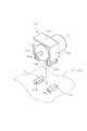
次に、モータ保持部の第1変形例を説明する。図5は、本発明の一実施形態に係るアクチュエータのモータ保持部の第1変形例およびそのモータ保持部を固定する下ケースの溝形状を示す。 Next, a first modification of the motor holding unit will be described. FIG. 5 shows a first modification of the motor holding portion of the actuator according to one embodiment of the present invention and the groove shape of the lower case that fixes the motor holding portion.
図5のモータ保持部28は、鉄板がプレス加工されて形成される。このモータ保持部28は、モータケース24の外周の頂面が接する平坦部28Aと、平坦部28Aに続いてモータケース24の外周の周面と接する側壁28Bと、下部にいくにつれて湾曲してくびれるコの字形状28Cと、くびれ部の先端がモータ20の軸方向に直交する方向に張り出した突条形状28Dとを有する。そして、下ケース12には、突条形状28Dを係止する係止凹部(溝形状)15が2つ軸方向に設けられ、係止凹部(溝形状)の開口15Aが対向配置されている。
The
モータ20を下ケース12に組み込む際には、モータ保持部28は、モータ20を保持し、モータ20を回転軸21の軸方向における位置を調整しながら、側壁28B下部の両側を押して突条形状28Dを下ケース12の溝形状の開口15Aに係止(固定)するものである。このような形状であっても、上述の実施形態と同様な効果を有すると共に、ネジ止めが不要となり部品が少なくなりコスト削減と作業時間が短縮できるものである。
When assembling the
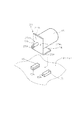
また、モータ保持部の第2変形例を説明する。図6は、本発明の一実施形態に係るアクチュエータのモータの保持部の第2変形例およびそのモータ保持部を固定する下ケースの溝形状を示す。 A second modification of the motor holding part will be described. FIG. 6 shows a second modification of the motor holding portion of the actuator according to the embodiment of the present invention and the groove shape of the lower case that fixes the motor holding portion.
この第2変形例のモータ保持部29は、断面略L字形状であり、モータ保持部29のベース部27Bには、モータ20の軸方向に直交する方向に張り出す突条形状29Aが設けられる。
下ケース12には、突条形状29Aを係止する係止凹部(溝形状)15が2つ軸方向に設けられ、係止凹部(溝形状)の開口15Aが対向配置されている。モータ20を下ケース12に組み込む際には、モータ保持部29の突条形状29Aを溝形状15にスライドさせながらモータ20を回転軸21の軸方向における位置を調整して固定する。このような形状であっても、上述の実施形態と同様な効果を有する。
The
The
図7(a)は、本発明の一実施形態に係るモータの変形例の正面図であり、図7(b)は、(a)の側面図である。
以上の説明では、モータ20にはモータ保持部が取り付けられているが、図7に示すように、突条形状23Aがモータケース24の外周面に一体に設けられ、このモータ20が直接下ケース12に固定されてもよい。
このように構成すると、上述の実施形態と同様な効果を有すると共に、モータ保持部やネジ止めが不要となり部品点数が少なくなるためコスト削減と作業時間が短縮できるものである。
Fig.7 (a) is a front view of the modification of the motor which concerns on one Embodiment of this invention, FIG.7 (b) is a side view of (a).
In the above description, the
With this configuration, the same effects as those of the above-described embodiment are obtained, and the motor holding portion and screwing are not required, and the number of parts is reduced, so that cost reduction and work time can be reduced.
図8(a)は、本発明の一実施形態に係り、変形例のウォームを有するモータを組み込んだ状態のアクチュエータの上ケースを除いた平面図であり、図8(b)は、(a)の切断線C−Cの断面図である。図2では、回転軸の先端22は、ウォーム26から突出する形状であったが、図8に示すように、回転軸21は、ウォーム26が被せられた形状であってもよい。本発明では、回転軸の先端22とは、回転軸21がウォーム26から突出した形状や、回転軸21にウォーム26が被せられた形状をいう。
FIG. 8A is a plan view of an actuator according to an embodiment of the present invention, excluding an upper case of an actuator in which a motor having a modified worm is incorporated, and FIG. It is sectional drawing of cutting line CC of no. In FIG. 2, the
なお、回転軸の他端がスラストプレートに当接した状態で、回転軸の先端とスラスト受部との隙間が極限まで小さく設定されてもよい。この隙間は、モータの回転軸のスラスト方向の遊び量に比べ、極めて小さくなる。このように構成すると回転軸のスラスト移動がほとんどなくなり打音が著しく低減できる。 Note that the gap between the tip of the rotating shaft and the thrust receiving portion may be set as small as possible while the other end of the rotating shaft is in contact with the thrust plate. This gap is extremely small compared to the amount of play in the thrust direction of the rotating shaft of the motor. If comprised in this way, the thrust movement of a rotating shaft will hardly exist and a striking sound can be reduced significantly.
また、モータを下ケースに固定する際に、モータの突条形状は、下ケースの収容凹部の開口方向(矢印Y方向)に沿って下ケースの溝形状に圧入され嵌合されるため、モータは、回転軸の軸方向(矢印X方向)に移動することなく下ケースに嵌合することでき、モータケース蓋と下ケース内側面との隙間を大きく設ける必要がなく、ケースを小型化できる。 In addition, when fixing the motor to the lower case, the motor's ridge shape is press-fitted and fitted into the groove shape of the lower case along the opening direction (arrow Y direction) of the housing recess of the lower case. Can be fitted into the lower case without moving in the axial direction (arrow X direction) of the rotary shaft, and it is not necessary to provide a large gap between the motor case lid and the inner surface of the lower case, thereby reducing the size of the case.
1 アクチュエータ
10 ケース
11 上ケース
12 下ケース
13 スラスト受部
14 溝形状
15 係止凹部(溝形状)
15A 係止凹部(溝形状)の開口
20 モータ
21 回転軸
22 回転軸の先端
22A ウォームの先端
23 突条形状
23A 突条形状
24 モータケース
24A モータケースの底部
25 モータケース蓋
26 ウォーム
27 モータ保持部
27A 立上部
27A1 ネジ
27B ベース部
28 モータ保持部
28A 平坦部
28B 側壁
28C コの字形状
28D 突条形状
29 モータ保持部
29A 突条形状
30 ギヤ
31 第1ギヤ
32 第2ギヤ
33 出力ギヤ(出力軸)
DESCRIPTION OF
15A Opening of a locking recess (groove shape) 20
Claims (2)
前記ケース内には、前記モータの回転軸の先端側に、前記回転軸のスラスト移動を制限するスラスト受部が配置され、
前記ケースと前記モータにはそれぞれ、前記モータを前記回転軸の軸方向における位置を調整して固定できる固定手段が設けられ、
前記固定手段は、前記モータに設けられ前記回転軸の軸方向に形成された突条形状もしくは溝形状からなるモータ側固定手段と、前記モータ側固定手段に嵌合するものであって前記ケース内に設けられ前記回転軸の軸方向に形成された溝形状もしくは突条形状からなるケース側固定手段とからなることを特徴とするアクチュエータ。 An actuator comprising a case, a motor provided in the case and having a worm fixed to a rotating shaft, and a gear meshing with the worm,
In the case, a thrust receiving portion for restricting thrust movement of the rotary shaft is disposed on the tip side of the rotary shaft of the motor,
Each of the case and the motor is provided with a fixing means capable of fixing the motor by adjusting the position in the axial direction of the rotating shaft,
The fixing means includes a motor-side fixing means that is provided on the motor and has a ridge shape or a groove shape formed in the axial direction of the rotating shaft, and is fitted into the motor-side fixing means. And a case-side fixing means having a groove shape or a ridge shape formed in the axial direction of the rotating shaft.
The actuator according to claim 1, wherein the motor side fixing means is provided in a motor case of the motor.
Priority Applications (1)
| Application Number | Priority Date | Filing Date | Title |
|---|---|---|---|
| JP2010263828A JP2012111421A (en) | 2010-11-26 | 2010-11-26 | Actuator |
Applications Claiming Priority (1)
| Application Number | Priority Date | Filing Date | Title |
|---|---|---|---|
| JP2010263828A JP2012111421A (en) | 2010-11-26 | 2010-11-26 | Actuator |
Publications (1)
| Publication Number | Publication Date |
|---|---|
| JP2012111421A true JP2012111421A (en) | 2012-06-14 |
Family
ID=46496102
Family Applications (1)
| Application Number | Title | Priority Date | Filing Date |
|---|---|---|---|
| JP2010263828A Pending JP2012111421A (en) | 2010-11-26 | 2010-11-26 | Actuator |
Country Status (1)
| Country | Link |
|---|---|
| JP (1) | JP2012111421A (en) |
Cited By (6)
| Publication number | Priority date | Publication date | Assignee | Title |
|---|---|---|---|---|
| DE202012007957U1 (en) | 2012-08-20 | 2012-10-16 | Sony Corporation | battery Pack |
| DE202012007956U1 (en) | 2012-08-20 | 2012-10-17 | Sony Corporation | battery Pack |
| DE202012007958U1 (en) | 2012-08-20 | 2012-10-17 | Sony Corporation | battery Pack |
| DE202012007955U1 (en) | 2012-08-20 | 2012-10-17 | Sony Corporation | battery Pack |
| EP2665106A1 (en) | 2012-05-15 | 2013-11-20 | Sony Corporation | Battery pack |
| JP2014151711A (en) * | 2013-02-06 | 2014-08-25 | Denso Corp | Device |
-
2010
- 2010-11-26 JP JP2010263828A patent/JP2012111421A/en active Pending
Cited By (8)
| Publication number | Priority date | Publication date | Assignee | Title |
|---|---|---|---|---|
| EP2665106A1 (en) | 2012-05-15 | 2013-11-20 | Sony Corporation | Battery pack |
| EP2665107A1 (en) | 2012-05-15 | 2013-11-20 | Sony Corporation | Battery pack |
| EP2897190A1 (en) | 2012-05-15 | 2015-07-22 | Sony Corporation | Battery pack |
| DE202012007957U1 (en) | 2012-08-20 | 2012-10-16 | Sony Corporation | battery Pack |
| DE202012007956U1 (en) | 2012-08-20 | 2012-10-17 | Sony Corporation | battery Pack |
| DE202012007958U1 (en) | 2012-08-20 | 2012-10-17 | Sony Corporation | battery Pack |
| DE202012007955U1 (en) | 2012-08-20 | 2012-10-17 | Sony Corporation | battery Pack |
| JP2014151711A (en) * | 2013-02-06 | 2014-08-25 | Denso Corp | Device |
Similar Documents
| Publication | Publication Date | Title |
|---|---|---|
| JP2012111421A (en) | Actuator | |
| KR101543673B1 (en) | Linear Stepping motor | |
| EP1529984A2 (en) | Motor with reduction mechanism and power seat motor with reduction mechanism | |
| JP2010124621A (en) | Motor with decelerator mechanism | |
| JPWO2012029608A1 (en) | Wiper motor | |
| JP5059651B2 (en) | Motor actuator | |
| JP2019075974A (en) | Drive unit | |
| JP2012521510A (en) | Electrical equipment with built-in damping parts for transmission parts | |
| JP6608387B2 (en) | Motor with reduction mechanism | |
| JP2008174024A (en) | Electric power steering device | |
| JP5931697B2 (en) | Motor equipment | |
| JP5563910B2 (en) | Motor with reduction mechanism | |
| JP5546211B2 (en) | Motor with reduction mechanism | |
| JP2008141917A (en) | Motor | |
| JP4630838B2 (en) | Steering lock device | |
| JP6267895B2 (en) | Motor equipment | |
| JP5129726B2 (en) | Motor with reduction mechanism | |
| JP2010124620A (en) | Motor with decelerator mechanism | |
| KR20120110121A (en) | Bearing cover having a bearing function | |
| JP6793556B2 (en) | Motor with reduction mechanism | |
| JP2010098796A (en) | Motor with speed reducer | |
| WO2022244359A1 (en) | Actuator and actuator manufacturing method | |
| JP2016046990A (en) | Motor device | |
| JP2014212647A (en) | Electric actuator | |
| JP5249444B1 (en) | Intake air amount control device for internal combustion engine |