JP2012106956A - Purification method of polymerizable compound - Google Patents
Purification method of polymerizable compound Download PDFInfo
- Publication number
- JP2012106956A JP2012106956A JP2010257938A JP2010257938A JP2012106956A JP 2012106956 A JP2012106956 A JP 2012106956A JP 2010257938 A JP2010257938 A JP 2010257938A JP 2010257938 A JP2010257938 A JP 2010257938A JP 2012106956 A JP2012106956 A JP 2012106956A
- Authority
- JP
- Japan
- Prior art keywords
- polymerizable compound
- water
- absorption tower
- vent gas
- gas absorption
- Prior art date
- Legal status (The legal status is an assumption and is not a legal conclusion. Google has not performed a legal analysis and makes no representation as to the accuracy of the status listed.)
- Granted
Links
Images

Landscapes
- Organic Low-Molecular-Weight Compounds And Preparation Thereof (AREA)
Abstract
Description
本発明は、重合性化合物の精製方法に関する。 The present invention relates to a method for purifying a polymerizable compound.
化学工場においては、液体をタンク内に貯蔵して用いるのが一般的である。ここで、タンクは、通常閉じた構造を有するものが用いられている。そのため、タンク内の液量の増減や、タンク周辺の気温の変化によって、タンク内の圧力が変動する。そして、タンク内の圧力の変動は、タンクにストレスを与える。例えば、タンクの設計圧を超えた場合や、また、負圧対策を行っていないタンクにおいて、タンク周辺の圧力を下回る圧力になった場合には、タンクが損傷する危険がある。したがって、タンクが損傷する事態を回避するため、タンク内の圧力の変動を防止する必要がある。タンク内の圧力の変動を防止する方法として、例えば、タンク内の気相部分において、気体の排出・供給が可能な導管を設置し、タンク内の圧力を制御する方法が挙げられる。当該方法によれば、タンク内の圧力が増加した場合には、前記導管からタンク内の気体を外部に排出し、タンク内の圧力が減少した場合には、前記導管から不活性ガスをタンク内に供給し、タンク内の圧力を一定に維持することができる。このようなタンク内の圧力を一定に維持する装置をタンクのベント装置と呼び、該装置から排出される気体をベントガスと呼ぶ。 In chemical factories, it is common to store liquids in tanks. Here, a tank having a normally closed structure is used. Therefore, the pressure in the tank fluctuates due to the increase or decrease in the amount of liquid in the tank or the change in the temperature around the tank. And the fluctuation | variation of the pressure in a tank gives a stress to a tank. For example, when the pressure exceeds the design pressure of the tank or when the pressure is lower than the pressure around the tank in a tank that does not take negative pressure countermeasures, there is a risk of damage to the tank. Therefore, in order to avoid a situation where the tank is damaged, it is necessary to prevent fluctuations in pressure in the tank. As a method for preventing the fluctuation of the pressure in the tank, for example, a method of controlling the pressure in the tank by installing a conduit capable of discharging and supplying the gas in the gas phase portion in the tank. According to the method, when the pressure in the tank increases, the gas in the tank is discharged from the conduit to the outside, and when the pressure in the tank decreases, the inert gas is discharged from the conduit into the tank. The pressure in the tank can be kept constant. A device that maintains a constant pressure in the tank is called a tank vent device, and a gas discharged from the device is called a vent gas.
また、タンクのベントガス中には、タンク内に貯蔵されている液体が気化した気体が含まれている。該液体が気化した気体は大気を汚染する物質である場合、そのまま大気に放出することができない。このような大気汚染物質を含むベントガスを浄化する方法として、例えばベントガス吸収塔を設置して吸収液により大気汚染物質を含むベントガスを浄化する方法等が挙げられる。 Further, the vent gas of the tank contains a gas obtained by vaporizing the liquid stored in the tank. When the gas which the liquid vaporized is a substance which pollutes air | atmosphere, it cannot discharge | release to air | atmosphere as it is. As a method of purifying vent gas containing such air pollutants, for example, a method of installing a vent gas absorption tower and purifying vent gas containing air pollutants with an absorbing solution can be cited.
例えば特許文献1には、ベントガス吸収塔の吸収液として水を使用し、ベントガスを吸収させた水を活性汚泥処理装置へと供給する方法が記載されている。
For example,
しかしながら、特許文献1に記載の方法を、重合性化合物を貯蔵しているタンクのベントガス吸収塔に適用した場合、ベントガス中に含まれる重合性化合物によりベントガス吸収塔が汚れ、長期間運転すると吸収効率が落ちてしまうという問題がある。
特に、ベントガス吸収塔を有する精製装置で重合性化合物を精製する方法において、ベントガス吸収塔が汚れると、ベントガス吸収塔の吸収効率が低下するだけでなく、重合性化合物の精製も安定して行うことが困難となる。
そこで、本発明は、ベントガス吸収塔を有する精製装置で重合性化合物を精製する方法において、ベントガス吸収塔の汚れを防止し、ベントガス吸収塔の吸収効率を長期間維持しつつ、長期間安定的に重合性化合物を精製する方法を提供することを目的とする。
However, when the method described in
In particular, in a method for purifying a polymerizable compound with a purification apparatus having a vent gas absorption tower, if the vent gas absorption tower becomes dirty, not only the absorption efficiency of the vent gas absorption tower decreases, but also the purification of the polymerizable compound should be performed stably. It becomes difficult.
Therefore, the present invention provides a method for purifying a polymerizable compound using a purification apparatus having a vent gas absorption tower, preventing contamination of the vent gas absorption tower, maintaining the absorption efficiency of the vent gas absorption tower for a long time, and stably for a long time. It aims at providing the method of refine | purifying a polymeric compound.
本発明者は、上記課題を克服するため鋭意検討した結果、重合性化合物を貯蔵するタンクに接続されたベントガス吸収塔における吸収液として、重合性化合物を精製するプロセスで使用された水を利用することにより、ベントガス吸収塔の汚れを抑制し、長期間安定的にベントガス吸収塔を運転できるとともに、長期間安定して重合性化合物を精製することができることを見出し、本発明を完成するに至った。
すなわち、本発明は以下のとおりである。
[1]
精製装置で重合性化合物を精製する方法であって、
前記精製装置が、重合性化合物と水との分離部と、重合性化合物の貯蔵部と、該貯蔵部に接続したベントガス吸収塔とを含み、
前記分離部で重合性化合物と水とを分離する工程と、
前記分離部で分離した水を、前記ベントガス吸収塔における吸収液として供給する工程とを含む重合性化合物の精製方法。
[2]
前記精製装置が、重合性化合物と水との接触部を含み、
前記接触部で重合性化合物を水に接触させる工程を含む、[1]に記載の重合性化合物の精製方法。
[3]
前記分離部で分離した水が重合防止剤を含む、[1]または[2]に記載の重合性化合物の精製方法。
[4]
前記接触部で重合性化合物を水に溶解して得られた水溶液とともに、前記ベントガス吸収塔の塔底流を前記分離部に供給する、[2]に記載の重合性化合物の精製方法。
[5]
前記精製装置が、廃水焼却炉用空気ブロワまたは廃ガス焼却炉空気ブロワを含み、
前記ベントガス吸収塔塔頂の出口ガスを、廃水焼却炉用空気ブロワの吸引側、または廃ガス焼却炉空気ブロワの吸引側に導く、[1]〜[4]のいずれかに記載の重合性化合物の精製方法。
[6]
[1]〜[5]のいずれかに記載の精製方法により精製された重合性化合物。
[7]
重合性化合物と水との分離部と、
重合性化合物の貯蔵部と、
該貯蔵部に接続したベントガス吸収塔とを含み、
前記分離部と前記ベントガス吸収塔とが接続されており、
前記分離部で分離した水を、前記ベントガス吸収塔に供給する精製装置。
[8]
さらに、重合性化合物と水との接触部を含み、
前記ベントガス吸収塔における吸収液を前記分離部に供給する、[7]に記載の精製装置。
As a result of diligent studies to overcome the above problems, the present inventor utilizes water used in the process of purifying the polymerizable compound as an absorbing solution in a vent gas absorption tower connected to a tank for storing the polymerizable compound. As a result, it was found that the contamination of the vent gas absorption tower can be suppressed, the vent gas absorption tower can be stably operated for a long period of time, and the polymerizable compound can be purified stably for a long period of time, and the present invention has been completed. .
That is, the present invention is as follows.
[1]
A method for purifying a polymerizable compound with a purification apparatus,
The purification apparatus includes a polymerizable compound and water separation unit, a polymerizable compound storage unit, and a vent gas absorption tower connected to the storage unit,
Separating the polymerizable compound and water in the separation part;
And a step of supplying the water separated in the separation section as an absorbent in the vent gas absorption tower.
[2]
The purification apparatus includes a contact portion between a polymerizable compound and water,
The method for purifying a polymerizable compound according to [1], including a step of bringing the polymerizable compound into contact with water at the contact portion.
[3]
The method for purifying a polymerizable compound according to [1] or [2], wherein the water separated in the separation unit contains a polymerization inhibitor.
[4]
The method for purifying a polymerizable compound according to [2], wherein a bottom stream of the bent gas absorption tower is supplied to the separation part together with an aqueous solution obtained by dissolving the polymerizable compound in water at the contact part.
[5]
The purification apparatus includes a waste water incinerator air blower or a waste gas incinerator air blower,
The polymerizable compound according to any one of [1] to [4], wherein an outlet gas at the top of the vent gas absorption tower is led to a suction side of a waste water incinerator air blower or a suction side of a waste gas incinerator air blower. Purification method.
[6]
[1] A polymerizable compound purified by the purification method according to any one of [5].
[7]
A separation part of the polymerizable compound and water;
A reservoir of polymerizable compounds;
A vent gas absorption tower connected to the storage section,
The separation unit and the vent gas absorption tower are connected,
A purification apparatus for supplying water separated by the separation unit to the vent gas absorption tower.
[8]
Furthermore, including a contact portion between the polymerizable compound and water,
The purification apparatus according to [7], wherein an absorption liquid in the vent gas absorption tower is supplied to the separation unit.
本発明により、重合性化合物を貯蔵するタンクに接続されたベントガス吸収塔の汚れを抑制し、ベントガス吸収塔を長期間安定的に運転することができるとともに、長期間安定して重合性化合物を精製することができる。 According to the present invention, contamination of a vent gas absorption tower connected to a tank for storing a polymerizable compound can be suppressed, the vent gas absorption tower can be stably operated for a long time, and the polymerizable compound can be purified stably for a long time. can do.
以下、本発明を実施するための形態(以下、「本実施の形態」という)について詳細に説明する。なお、本発明は、以下の実施の形態に制限されるものではなく、その要旨の範囲内で種々変形して実施することができる。
本実施の形態の重合性化合物の精製方法は、精製装置で重合性化合物を精製する方法であって、前記精製装置が、重合性化合物と水との分離部と、重合性化合物の貯蔵部と、該貯蔵部に接続したベントガス吸収塔とを含み、前記分離部で重合性化合物と水とを分離する工程と、前記分離部で分離した水を、前記ベントガス吸収塔における吸収液として供給する工程とを含む。
Hereinafter, a mode for carrying out the present invention (hereinafter referred to as “the present embodiment”) will be described in detail. In addition, this invention is not restrict | limited to the following embodiment, In the range of the summary, various deformation | transformation can be implemented.
The method for purifying a polymerizable compound according to the present embodiment is a method for purifying a polymerizable compound using a purifier, wherein the purifier includes a separation unit for the polymerizable compound and water, a storage unit for the polymerizable compound, A step of separating the polymerizable compound and water in the separation unit, and a step of supplying the water separated in the separation unit as an absorption liquid in the vent gas absorption tower. Including.
本明細書中、重合性化合物とは、分子内に重合しうる二重結合を有する化合物を言い、触媒の作用により重合反応が進行する化合物を包含する。
重合性化合物の具体例としては、アクリル酸、メタクリル酸等の不飽和カルボン酸;アクリル酸メチル、アクリル酸エチル、アクリル酸ブチル、アクリル酸−2−エチルヘキシル、アクリル酸オクチル、アクリル酸−2−ヒドロキシエチル、アクリル酸−2−ヒドロキシプロピル、メタクリル酸メチル、メタクリル酸ブチル等の(メタ)アクリル酸エステルや酢酸ビニル等の不飽和カルボン酸エステル類;(メタ)アクリロニトリル、アクリルアミド等のアクリル化合物;スチレン、α−メチルスチレン、ジビニルベンゼン等の芳香族ビニル化合物が挙げられる。中でも、(メタ)アクリロニトリルが好ましい。
In the present specification, the polymerizable compound means a compound having a double bond that can be polymerized in a molecule, and includes a compound in which a polymerization reaction proceeds by the action of a catalyst.
Specific examples of the polymerizable compound include unsaturated carboxylic acids such as acrylic acid and methacrylic acid; methyl acrylate, ethyl acrylate, butyl acrylate, 2-ethylhexyl acrylate, octyl acrylate, 2-hydroxy acrylate (Meth) acrylic acid esters such as ethyl, 2-hydroxypropyl acrylate, methyl methacrylate and butyl methacrylate, and unsaturated carboxylic acid esters such as vinyl acetate; acrylic compounds such as (meth) acrylonitrile and acrylamide; styrene, Examples include aromatic vinyl compounds such as α-methylstyrene and divinylbenzene. Of these, (meth) acrylonitrile is preferable.
重合性化合物と水との分離部としては、例えば、蒸留塔、デカンター、膜分離が挙げられる。これらの分離部は、単独で用いてもよく、2つ以上併用してもよい。 Examples of the separation part of the polymerizable compound and water include a distillation tower, a decanter, and membrane separation. These separation parts may be used alone or in combination of two or more.
前記分離部で分離した水は、重合防止剤を含むことが好ましい。
分離部で分離した水が重合防止剤を含んでいると、分離部で分離した水とともに重合防止剤がベントガス吸収塔に供給されることになるので、ベントガス吸収塔内でも重合防止効果が得られる。また、本実施の形態において、ベントガス吸収塔における吸収液中の重合防止剤の濃度は25質量ppm以上であることが好ましい。当該重合防止剤の濃度の上限は、特に限定されないが10000ppm以下であることが好ましい。重合防止剤の濃度の測定方法は、使用する重合防止剤によって異なるが、イオンクロマトグラフィー、ガスクロマトグラフィー、液体クロマトグラフィー、分光光度計などの分析機器を用いて測定する方法が挙げられる。
重合防止剤は、重合性化合物の重合を抑制する機能を奏するものであれば特に限定されない。従って、本明細書中「重合防止剤」は、一般的に重合防止剤と定義されているものの他、重合禁止剤と称される場合があるものを含む概念である。重合防止剤の具体例としては、ハイドロキノンやメトキノン等のキノン類;ニトロフェノール、ターシャリーブチルカテコールなどフェノール類;ニトロソ基を有する有機化合物類;ニトロキシルラジカルを有する化合物類を挙げることができる。
The water separated in the separation part preferably contains a polymerization inhibitor.
If the water separated in the separation part contains a polymerization inhibitor, the polymerization inhibitor is supplied to the vent gas absorption tower together with the water separated in the separation part, so that the polymerization prevention effect can be obtained even in the vent gas absorption tower. . Moreover, in this Embodiment, it is preferable that the density | concentration of the polymerization inhibitor in the absorption liquid in a vent gas absorption tower is 25 mass ppm or more. The upper limit of the concentration of the polymerization inhibitor is not particularly limited, but is preferably 10,000 ppm or less. The method for measuring the concentration of the polymerization inhibitor varies depending on the polymerization inhibitor used, and examples thereof include a method of measuring using an analytical instrument such as ion chromatography, gas chromatography, liquid chromatography, and spectrophotometer.
The polymerization inhibitor is not particularly limited as long as it has a function of suppressing polymerization of the polymerizable compound. Accordingly, the “polymerization inhibitor” in the present specification is a concept including what is generally defined as a polymerization inhibitor and may be referred to as a polymerization inhibitor. Specific examples of the polymerization inhibitor include quinones such as hydroquinone and methoquinone; phenols such as nitrophenol and tertiary butyl catechol; organic compounds having a nitroso group; compounds having a nitroxyl radical.
重合性化合物の貯蔵部としては、例えば、タンク、ドラムが挙げられる。これらの貯蔵部は、単独で用いてもよく、2つ以上併用してもよい。
貯蔵部の構造や容量には特に制限がない。タンクおよびドラムの具体例としては、コーンルーフタンク、ドームルーフタンク、横型ドラム、縦型ドラムなどの各タイプのタンクおよびドラムを挙げることができる。
貯蔵部は、収容する重合性化合物との接触や、周囲の環境によって腐食等の影響を受けない材質からなることが好ましい。重合性化合物のうち一般的な腐食性を有する重合性化合物用の貯蔵部としては、カーボンスチールからなるものが選ばれることが多い。腐食性が強い(メタ)アクリル酸および(メタ)アクリル酸エステル等を収容する貯蔵部としては、SUS304およびSUS316等の耐腐食性を有する材料からなるものが好ましい。
タンクやドラムなどの貯蔵部の形状や個数は特に限定されず、例えば、図1に示されているように、タンク3およびドラム4として異なる形状のものがそれぞれ1つ設けられていてもよく、収容する重合性化合物の物性や量等に鑑みて適宜設定される。つまり、同じ機能を有する貯蔵部が複数設けられてよく、それらの形状やサイズも同じでも異なってもよい。もちろん、場合によっては貯蔵部が1つでもよい。貯蔵部が複数設けられる場合、そのうち少なくとも1つをベントガス吸収塔に接続し、前記分離部で分離した水を、前記ベントガス吸収塔における吸収液として供給する態様であれば、本実施の形態の範疇である。
As a storage part of a polymeric compound, a tank and a drum are mentioned, for example. These storage units may be used alone or in combination of two or more.
There is no particular limitation on the structure and capacity of the storage unit. Specific examples of the tank and drum include various types of tanks and drums such as a cone roof tank, a dome roof tank, a horizontal drum, and a vertical drum.
The storage part is preferably made of a material that is not affected by corrosion or the like due to contact with the polymerizable compound to be accommodated or the surrounding environment. Of the polymerizable compounds, a storage portion for a polymerizable compound having general corrosive properties is often selected from carbon steel. As the storage unit for storing (meth) acrylic acid and (meth) acrylic acid ester having strong corrosivity, those made of a material having corrosion resistance such as SUS304 and SUS316 are preferable.
The shape and the number of storage units such as tanks and drums are not particularly limited. For example, as shown in FIG. 1, one of different shapes may be provided as the
前記貯蔵部に接続したベントガス吸収塔としては、特に制限はなく、公知の吸収装置を用いることができる。このような吸収装置の一例として、気液接触型の充填塔を挙げることができる。これは、充填物が充填された塔の下部より処理する気体を導入し、塔上部から気体を吸収する液体(吸収液)を導入して、該塔内で気体と液体とを接触させ、気体を液体中に吸収させる装置である。当該装置における充填物としては特に制限はなく、公知の充填物である、カスケードミリリング、ポールリング、ラシヒリング、メラパック、テラレットなどを用いることができる。 There is no restriction | limiting in particular as a vent gas absorption tower connected to the said storage part, A well-known absorber can be used. As an example of such an absorber, a gas-liquid contact type packed tower can be mentioned. This is because the gas to be treated is introduced from the lower part of the tower filled with the packing, the liquid (absorbing liquid) that absorbs the gas is introduced from the upper part of the tower, the gas is brought into contact with the liquid in the tower, the gas Is a device that absorbs water into a liquid. There is no restriction | limiting in particular as a filler in the said apparatus, Cascade Milling, a pole ring, a Raschig ring, a melapack, a terralet etc. which are well-known fillers can be used.
ベントガス吸収塔の運転条件は、吸収させる気体の種類、その濃度に依存する。
ベントガス中の重合性化合物の濃度は、
(タンク気相部温度における重合性化合物の蒸気圧)/(タンク気相部温度における全圧)×100
で算出される。
例えばアクリロニトリルを貯蔵している常圧タンクの温度が25℃の場合、ベントガス中のアクリロニトリル濃度は約15容積%である。この場合、ベントガス吸収塔の運転条件としては、吸収水を常温で供給し、ベントガス吸収塔の圧力を常圧とするのが設備面および経済面から好ましい。なお、ベントガス吸収塔の吸収水の供給量は、多いほどベントガス吸収塔塔頂ガス中の重合性化合物濃度を下げることができるが、その分ベントガス吸収塔塔底液量が増え、処理費がかさむこととなるため、大気汚染防止の面および経済面の両面から適切な量を決めることが好ましい。
The operating conditions of the vent gas absorption tower depend on the type of gas to be absorbed and its concentration.
The concentration of the polymerizable compound in the vent gas is
(Vapor pressure of polymerizable compound at tank gas phase temperature) / (Total pressure at gas phase temperature of tank) × 100
Is calculated by
For example, when the temperature of the atmospheric tank storing acrylonitrile is 25 ° C., the concentration of acrylonitrile in the vent gas is about 15% by volume. In this case, as operating conditions of the vent gas absorption tower, it is preferable from the viewpoint of facilities and economy that the absorption water is supplied at normal temperature and the pressure of the vent gas absorption tower is set to normal pressure. As the amount of absorbed water supplied to the vent gas absorption tower increases, the concentration of the polymerizable compound in the gas at the top of the vent gas absorption tower can be lowered, but the amount of liquid at the bottom of the vent gas absorption tower increases and the processing cost increases accordingly. Therefore, it is preferable to determine an appropriate amount from the viewpoints of air pollution prevention and economy.
本実施の形態の重合性化合物の精製方法は、前記精製装置が、重合性化合物と水との接触部を含み、前記接触部で重合性化合物を水に接触させる工程を含むことが好ましい。
重合性化合物と水との接触部としては、気液接触型の充填塔や棚段塔、液液抽出装置のスプレー塔や充填塔が挙げられる。
気液接触型の充填塔や液液抽出装置の充填塔の塔内には充填物が充填されている。当該充填物としては特に制限はなく、公知の充填物である、カスケードミリリング、ポールリング、ラシヒリング、メラパック、テラレットなどを用いることができる。
重合性化合物を水に接触させる工程において、前記接触部に、重合性化合物を含む流体が供給される態様が好ましい。当該流体としてはガス、液体、ガスと液体との混合物、ガスと固体と液体との混合物のいずれでもよい。
本実施の形態の重合性化合物の精製方法は、前記接触部で重合性化合物を水に溶解して得られた水溶液とともに、前記ベントガス吸収塔の塔底流を前記分離部に供給することが好ましい。これにより、ベントガス中の重合性化合物をより多く回収できるため、好ましい。
In the purification method of the polymerizable compound of the present embodiment, it is preferable that the purification apparatus includes a contact portion between the polymerizable compound and water, and a step of bringing the polymerizable compound into contact with water at the contact portion.
Examples of the contact portion between the polymerizable compound and water include gas-liquid contact type packed towers and plate towers, and spray towers and packed towers of liquid-liquid extraction devices.
The inside of the gas-liquid contact type packed tower or the packed tower of the liquid-liquid extraction apparatus is filled with a packing material. There is no restriction | limiting in particular as the said filler, A cascade milling, a pole ring, a Raschig ring, a melapack, a terralet etc. which are well-known fillings can be used.
In the step of bringing the polymerizable compound into contact with water, a mode in which a fluid containing the polymerizable compound is supplied to the contact portion is preferable. The fluid may be any of gas, liquid, a mixture of gas and liquid, and a mixture of gas, solid and liquid.
In the purification method of the polymerizable compound of the present embodiment, it is preferable to supply the bottom stream of the bent gas absorption tower to the separation unit together with an aqueous solution obtained by dissolving the polymerizable compound in water at the contact unit. This is preferable because more polymerizable compound in the vent gas can be recovered.
本実施の形態の重合性化合物の精製方法は、前記精製装置が、廃水焼却炉用空気ブロワまたは廃ガス焼却炉空気ブロワを含み、前記ベントガス吸収塔塔頂の出口ガスを、廃水焼却炉用空気ブロワの吸引側、または廃ガス焼却炉空気ブロワの吸引側に導くことが好ましい。これにより、ベントガス吸収塔塔頂の出口ガスが、廃水焼却炉または廃ガス焼却炉で無害化処理されるので、大気汚染を防止することができる。
また、本実施の形態の重合性化合物の精製方法は、前記精製装置が、ベントガス吸収塔塔頂ガス吸引ブロワを含み、ベントガス吸収塔塔頂ガスを吸引することが好ましい。
なお、本実施の形態の重合性化合物の精製方法は、上述のとおりベントガス吸収塔塔頂の出口ガス等の、廃水または廃ガスを、廃水焼却炉または廃ガス焼却炉で無害化処理する工程を含んでいてもよく、その他の排水を活性汚泥処理設備で無害化する工程などを含んでいてもよい。
本実施の形態の重合性化合物は、上述の精製方法により精製された重合性化合物である。本実施の形態の重合性化合物は、上述の精製方法により精製されるので、長期間安定的かつ効率的に得ることができる。
In the purification method of the polymerizable compound of the present embodiment, the purification apparatus includes a waste water incinerator air blower or a waste gas incinerator air blower, and the outlet gas at the top of the vent gas absorption tower is used as waste water incinerator air. It is preferable to lead to the suction side of the blower or the suction side of the waste gas incinerator air blower. Thereby, since the exit gas at the top of the vent gas absorption tower is detoxified in the waste water incinerator or the waste gas incinerator, air pollution can be prevented.
In the purification method of the polymerizable compound of the present embodiment, it is preferable that the purification apparatus includes a vent gas absorption tower top gas suction blower and sucks the vent gas absorption tower top gas.
In addition, the purification method of the polymerizable compound according to the present embodiment includes a step of detoxifying waste water or waste gas, such as the outlet gas at the top of the vent gas absorption tower as described above, in a waste water incinerator or a waste gas incinerator. It may contain, and the process etc. which detoxify other waste_water | drain with activated sludge processing equipment may be included.
The polymerizable compound of the present embodiment is a polymerizable compound purified by the above-described purification method. Since the polymerizable compound of the present embodiment is purified by the above purification method, it can be obtained stably and efficiently for a long period of time.
本実施の形態の精製装置は、重合性化合物と水との分離部と、重合性化合物の貯蔵部と、該貯蔵部に接続したベントガス吸収塔とを含み、前記分離部と前記ベントガス吸収塔とが接続されており、前記分離部で分離した水を、前記ベントガス吸収塔に供給する精製装置である。
本実施の形態の精製装置は、前記分離部で分離した水を、前記ベントガス吸収塔に供給しているので、ベントガス吸収塔の汚れを抑制し、ベントガス吸収塔を長期間安定的に運転することができるとともに、長期間安定して重合性化合物を精製することができる。
また、本実施の形態の精製装置は、さらに、重合性化合物と水との接触部を含み、前記ベントガス吸収塔における吸収液を前記分離部に供給することが好ましい。これにより、ベントガス中の重合性化合物をより多く回収できるため、好ましい。
さらに、本実施の形態の精製装置は、廃水焼却炉用空気ブロワもしくは廃ガス焼却炉空気ブロワ、ベントガス吸収塔塔頂ガス吸引ブロワ、廃水焼却炉もしくは廃ガス焼却炉、活性汚泥処理設備などを含んでいてもよい。
なお、本実施の形態の精製装置において、分離部、貯蔵部、ベントガス吸収塔、接触塔および重合性化合物などの構成要件は、上述の精製方法の場合と同様である。
The purification apparatus of the present embodiment includes a separation unit for the polymerizable compound and water, a storage unit for the polymerizable compound, and a vent gas absorption tower connected to the storage unit, and the separation unit, the vent gas absorption tower, Is a purification device that supplies water separated by the separation unit to the vent gas absorption tower.
In the purification apparatus of the present embodiment, the water separated in the separation unit is supplied to the vent gas absorption tower, so that contamination of the vent gas absorption tower is suppressed, and the vent gas absorption tower is stably operated for a long period of time. In addition, the polymerizable compound can be purified stably for a long period of time.
Moreover, it is preferable that the refiner | purifier of this Embodiment further includes the contact part of a polymeric compound and water, and supplies the absorption liquid in the said vent gas absorption tower to the said separation part. This is preferable because more polymerizable compound in the vent gas can be recovered.
Furthermore, the purification apparatus of the present embodiment includes a waste water incinerator air blower or waste gas incinerator air blower, a vent gas absorption tower top gas suction blower, a waste water incinerator or waste gas incinerator, activated sludge treatment equipment, and the like. You may go out.
In the purifying apparatus of the present embodiment, the constituent elements such as the separation unit, the storage unit, the vent gas absorption tower, the contact tower, and the polymerizable compound are the same as those in the above purification method.
以下、精製のうち「蒸留」を例にとって、本実施の形態の重合性化合物の精製方法を図1〜5を用いてより詳細に説明するが、本実施の形態は図1〜5に示す態様に限定されない。また、本明細書中、精製は、蒸留に限定されず、重合性化合物と水との混合物が不純物を含む場合に、混合物から不純物の少なくとも一部を除去するためのその他の操作を含む概念である。従って、「精製」には蒸留の他、静置による液液分離を含み、「精製装置」は蒸留塔の他、デカンターを有する精製装置を包含する。 Hereinafter, the purification method of the polymerizable compound of the present embodiment will be described in more detail with reference to FIGS. 1 to 5 by taking “distillation” as an example of the purification, but this embodiment is an embodiment shown in FIGS. It is not limited to. Further, in the present specification, purification is not limited to distillation, and is a concept including other operations for removing at least a part of impurities from a mixture when the mixture of a polymerizable compound and water contains impurities. is there. Therefore, “purification” includes not only distillation but also liquid-liquid separation by standing, and “purification apparatus” includes a purification apparatus having a decanter in addition to a distillation column.
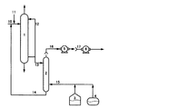
図1は、本発明の精製装置の一例を示す概略図である。該精製装置は、重合性化合物と水との分離部として蒸留塔1を含み、また重合性化合物の貯蔵部としてタンク3およびドラム4を含み、さらに該貯蔵部に接続したベントガス吸収塔2を含む。さらにまた、ベントガス吸収塔塔頂ガス吸引ブロワ5と、廃ガス焼却炉用または廃水焼却炉用の空気ブロワ6とを含む。そして、ベントガス吸収塔2は蒸留塔1に接続されている。
重合性化合物は接触塔(図1には示されていない)内で水に接触し、水溶液となってフィード配管10を通じて蒸留塔1に供給され、蒸留塔1内で抽出蒸留される。蒸留塔1に供給される直前で、フィード配管11から重合防止剤が添加され、蒸留塔1内での重合防止が図られる。
ベントガス吸収塔2の下部には、配管を介してタンク3およびドラム4が並列に接続されている。ベントガス吸収塔2に接続される配管は、タンク3およびドラム4の上端に接続され、配管はタンクおよびドラムの中で気体が存在する部分で開口するようになっている。
ベントガス吸収塔2の塔頂には第一および第二のブロワ5および6が縦列に接続されている。ベントガス吸収塔2の塔頂から塔頂出口ガスはライン16を通して第一のブロワ5で吸引され、ライン17を通して第二のブロワへ吸引される。ベントガス吸収塔2の塔頂配管とライン16とは、ベントガス吸収塔2がブロワ5の吸引圧の影響を直接受けないよう直結せず、10〜50cm程度の適当な間を空けておき、ライン16に調節弁を設け、ベントガス吸収塔2の圧力を調節することが好ましい。ブロワ5の吐出配管とライン17との間も同様に、ベントガス吸収塔2がブロワ6の吸引圧の影響を直接受けないよう直結せず、10〜50cm程度の適当な間を空けておき、ライン17に調節弁を設け、ベントガス吸収塔2の圧力を調節することが好ましい。
蒸留塔1に接続されたライン12を通じて塔底の近傍から塔頂の近傍へ循環させる塔内液をプロセス循環水という。このプロセス循環水のうち一部をベントガス吸収塔2のフィードライン13に導き、重合性化合物を貯蔵するタンク3およびドラム4のベントガスを吸収させる吸収液として利用する。重合性化合物を含んだベントガス吸収塔2の塔底液は、ライン14を通じて蒸留塔1のフィードラインに戻す。
ブロワ5はベントガス吸収塔塔頂ガスを吸引するためのブロワである。ブロワ5の吸引圧はベントガス吸収塔圧力、タンク圧力を維持できる圧力とする。ブロワ6は廃ガス焼却炉または廃水焼却炉用の空気ブロワである。そのため、ブロワ6の吸引圧は変動させず、ブロワ5の排出量がブロワ6の吸引量内に収まるようにする。
蒸留塔1にフィードされている重合防止剤はプロセス循環水にも含まれる。そのため、ベントガス吸収塔2における吸収液としてプロセス循環水を用いることで、ベントガス吸収塔2内でも重合防止効果が得られる。また、本プロセスにおけるベントガス吸収塔2の吸収液中の重合防止剤の濃度は25質量ppm以上であることが好ましい。
FIG. 1 is a schematic view showing an example of the purification apparatus of the present invention. The purification apparatus includes a
The polymerizable compound contacts water in a contact tower (not shown in FIG. 1), becomes an aqueous solution, is supplied to the
A
First and
The liquid in the tower that is circulated from the vicinity of the tower bottom to the vicinity of the tower top through the
The
The polymerization inhibitor fed to the
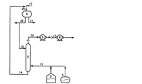
図2は蒸留塔を有する精製装置の別の例を示す。図2に示す装置は、蒸留塔1に接触塔7が接続されている以外、図1に示す例と同じであるので、相違点のみ以下に説明する。
フィードライン19を通じて、重合性化合物を含むガスが接触塔7に供給される。接触塔7は気液接触型の充填塔であって、塔内には上述した充填物が充填されている。 接触塔7上部から水が供給されて塔内で散布されるので、重合性化合物を含む流体は接触塔7内で水に接触して吸収される。生成した水溶液はライン10を通じて蒸留塔1に供給される。水の一部は蒸留塔1の下部から抜出され、フィードライン13を通じて吸収塔2に供給される他、ライン18を通じて接触塔7に供給されて再び吸収水となる。
接触塔7には重合性化合物を含む流体が供給される。流体はガス、液体、ガスと液体の混合物、ガスと固体と液体の混合物のいずれでもよい。重合性化合物を含む流体がガスの場合、当該流体は塔底付近から供給され、接触塔7内を上昇する。接触塔7内には塔頂付近から水が供給されるので、重合性化合物を含む流体は接触塔7内で水に接触し、水との混合物となって塔底から流出し、蒸留塔1に供給される。
接触塔7に供給される水は、蒸留塔の塔底付近から取得したプロセス循環水の一部を、ライン18を通じて分流したものである。プロセス循環水には重合防止剤が含まれているので、これを接触塔7の吸収水とすることで、接触塔7内の重合防止効果が期待される。
FIG. 2 shows another example of a purification apparatus having a distillation column. The apparatus shown in FIG. 2 is the same as the example shown in FIG. 1 except that the
A gas containing a polymerizable compound is supplied to the
A fluid containing a polymerizable compound is supplied to the
The water supplied to the
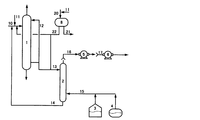
図3は、精製装置の更に別の例を概略的に示す。図3に示す例は、蒸留塔1に代えてデカンター8がベントガス吸収塔2に接続されている以外、図1に示す例と同じであるので、相違点のみ説明を行う。フィードライン20を通して重合性化合物および水などを含む混合物がデカンター8にフィードされるが、ライン20には重合防止剤を供給するためのライン11が接続されているので、デカンター8に供給される混合物は重合防止剤も含有する。デカンター8で重合性化合物を含む油層と水層とが比重差に従って分離された後、油層および水層は、順にライン21および22を通してデカンター8から排出され、別プロセスにフィードされる。デカンター8の水層の一部はライン22から分岐したライン13を通じてベントガス吸収塔2にフィードされ吸収水となる。デカンター8の水層は重合防止剤を含有するので、これをベントガス吸収塔2の吸収水とすることで、ベントガス吸収塔2内で重合防止効果を奏する。
FIG. 3 schematically shows still another example of the purification apparatus. The example shown in FIG. 3 is the same as the example shown in FIG. 1 except that the
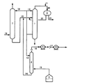
図4は、精製装置の更に別の例を概略的に示す。図4に示す例は、蒸留塔1に加えデカンター8もベントガス吸収塔2に接続されている以外、図1に示す例と同じであるので、相違点のみ説明を行う。デカンター8にはライン20を通じて重合防止剤を含有する重合性化合物が供給され、デカンター8内で水と分離される。デカンター8から排出される油層はライン21を通して別プロセスへと供給され、水層はライン22を通じてベントガス吸収塔2に供給されるほか、ライン10に供給されて蒸留塔1に入る。蒸留塔1のプロセス循環水とデカンター8の水層との両方が、ベントガス吸収塔2の吸収水として利用され、ベントガス吸収塔2の塔底液はライン14を通じて蒸留塔1のフィード配管10に接続されている。
FIG. 4 schematically shows still another example of the purification apparatus. The example shown in FIG. 4 is the same as the example shown in FIG. 1 except that the
図5に示す精製装置は、蒸留塔1の塔頂液がデカンター8に供給されている以外、図2に示す例とほぼ同じであるので、相違点のみ説明する。蒸留塔1の塔頂液はライン20を通じてデカンター8に供給される。また、ライン11からライン20に重合防止剤が供給され、デカンター8内の重合が防止される。蒸留塔1から供給された塔頂液は、デカンター8内で静置されると、油層と水層とに分離される。水層はライン22から抜出され、ライン10に合流して蒸留塔1に供給される。蒸留塔1の下部からの抜出し液は、ライン12、13、および18に分岐してそれぞれ蒸留塔1上部、ベントガス吸収塔2および接触塔7上部に供給されることで、プロセス水の有効利用が図られる。
The purification apparatus shown in FIG. 5 is substantially the same as the example shown in FIG. 2 except that the top liquid of the
次に本発明を実施例により具体的に説明するが、本発明は、以下の実施例に限定されない。以下の実施例で用いた精製装置の概略図を図5に示す。 EXAMPLES Next, although an Example demonstrates this invention concretely, this invention is not limited to a following example. A schematic diagram of the purification apparatus used in the following examples is shown in FIG.
[実施例1]
精製する重合性化合物としてアクリロニトリルを用いた。当該アクリロニトリルは、プロピレン、アンモニアおよび分子状酸素を反応させて製造した。
アクリロニトリルを製造するプロセスにおいて、プロピレン、アンモニアおよび分子状酸素を反応させて得られたアクリロニトリルを含む反応ガスを、ライン19を通して接触塔7に導入し、水と接触させた。接触塔7において、反応ガス中のアクリロニトリル等を水に吸収させ、反応しなかったプロピレンや酸素、窒素などのガスを塔頂より抜き出した。アクリロニトリル等を吸収させた水はライン10を通して蒸留塔1にフィードされた。蒸留塔1では水で抽出蒸留を行っており、接触塔7および蒸留塔1で用いられている水は蒸留塔1の下部より抜き出されるプロセス循環水を使用した。
蒸留塔1の塔頂から抜き出されたアクリロニトリルおよび水などを含むガスは、ライン20を通してデカンター8にフィードされた。重合防止剤としてハイドロキノン4質量%水溶液が、ライン11を通して、蒸留塔1の塔頂から抜き出されたアクリロニトリルおよび水などを含むガス全体に対して、約0.25質量%の割合でライン20に導入された。その後、アクリロニトリルおよび水などを含むガスを、冷却して液体としデカンター8で油水分離した。デカンター8で分離した水は、ライン22を通して蒸留塔1のフィードライン10に導入された。アクリロニトリルを含む油層を、ライン21を通して後の精製工程に導入し、精製されたアクリロニトリルが得られた。
精製したアクリロニトリルを貯蔵しているタンク3のベントガスはライン15を通してベントガス吸収塔2に導入されており、このベントガス吸収塔2における吸収液として、上記蒸留塔1の下部より抜き出されたプロセス循環水を用いた。該プロセス循環水は、ライン13を通してベントガス吸収塔2へとフィードされた。ベントガス吸収塔2の塔底液はライン14を通して蒸留塔1のフィードライン10へと戻された。
ベントガス吸収塔2を10年以上連続して運転したが、吸収能力の低下などは観測されなかった。また、この期間中におけるベントガス吸収塔2の吸収水中のハイドロキノン濃度は25〜55質量ppmであった。ハイドロキノン濃度は、分光光度計により測定した。さらに、この期間中、ベントガス吸収塔2の汚れを防止しつつ、安定的に重合性化合物を精製することができた。
[Example 1]
Acrylonitrile was used as the polymerizable compound to be purified. The acrylonitrile was produced by reacting propylene, ammonia and molecular oxygen.
In the process for producing acrylonitrile, a reaction gas containing acrylonitrile obtained by reacting propylene, ammonia and molecular oxygen was introduced into the
A gas containing acrylonitrile and water extracted from the top of the
The vent gas in the
The bent
[比較例1]
ベントガス吸収塔2における吸収液として、プロセス循環水でなく、工業用精製水を用いた以外は、実施例1と同様の操作を行った。その結果、5年でベントガス吸収塔2の内壁にポリマーが付着し、内壁から脱落したポリマーが吸収塔塔底出口ノズル周辺に堆積し、詰まりが発生した。
[Comparative Example 1]
The same operation as in Example 1 was performed except that industrial purified water was used instead of process circulating water as the absorbent in the vent
1 蒸留塔
2 ベントガス吸収塔
3 重合性化合物貯蔵タンク
4 重合性化合物貯蔵ドラム
5 ベントガス吸収塔塔頂ガス吸引ブロワ
6 廃ガス焼却炉用の空気ブロワまたは廃水焼却炉用の空気ブロワ
7 接触塔
10 蒸留塔フィードライン
11 重合防止剤のフィードライン
12 プロセス循環水ライン
13 ベントガス吸収塔フィードライン
14 ベントガス吸収塔塔底液戻りライン
15 ベントガスライン
16 ベントガス吸収塔塔頂ガスライン
17 廃ガス焼却炉用の空気ブロワ吸引側ラインまたは廃水焼却炉用の空気ブロワ吸引側ライン
18 接触塔の吸収水ライン
19 接触塔への反応ガスフィードライン
20 デカンターフィードライン
21 油層フィードライン
22 水層フィードライン
DESCRIPTION OF
Claims (8)
前記精製装置が、重合性化合物と水との分離部と、重合性化合物の貯蔵部と、該貯蔵部に接続したベントガス吸収塔とを含み、
前記分離部で重合性化合物と水とを分離する工程と、
前記分離部で分離した水を、前記ベントガス吸収塔における吸収液として供給する工程とを含む重合性化合物の精製方法。 A method for purifying a polymerizable compound with a purification apparatus,
The purification apparatus includes a polymerizable compound and water separation unit, a polymerizable compound storage unit, and a vent gas absorption tower connected to the storage unit,
Separating the polymerizable compound and water in the separation part;
And a step of supplying the water separated in the separation section as an absorbent in the vent gas absorption tower.
前記接触部で重合性化合物を水に接触させる工程を含む、請求項1に記載の重合性化合物の精製方法。 The purification apparatus includes a contact portion between a polymerizable compound and water,
The method for purifying a polymerizable compound according to claim 1, comprising a step of bringing the polymerizable compound into contact with water at the contact portion.
前記ベントガス吸収塔塔頂の出口ガスを、廃水焼却炉用空気ブロワの吸引側、または廃ガス焼却炉空気ブロワの吸引側に導く、請求項1〜4のいずれか一項に記載の重合性化合物の精製方法。 The purification apparatus includes a waste water incinerator air blower or a waste gas incinerator air blower,
The polymerizable compound according to any one of claims 1 to 4, wherein an outlet gas at the top of the vent gas absorption tower is led to a suction side of a waste water incinerator air blower or a suction side of a waste gas incinerator air blower. Purification method.
重合性化合物の貯蔵部と、
該貯蔵部に接続したベントガス吸収塔とを含み、
前記分離部と前記ベントガス吸収塔とが接続されており、
前記分離部で分離した水を、前記ベントガス吸収塔に供給する精製装置。 A separation part of the polymerizable compound and water;
A reservoir of polymerizable compounds;
A vent gas absorption tower connected to the storage section,
The separation unit and the vent gas absorption tower are connected,
A purification apparatus for supplying water separated by the separation unit to the vent gas absorption tower.
前記ベントガス吸収塔における吸収液を前記分離部に供給する、請求項7に記載の精製装置。 Furthermore, including a contact portion between the polymerizable compound and water,
The purification apparatus according to claim 7, wherein an absorption liquid in the vent gas absorption tower is supplied to the separation unit.
Priority Applications (1)
| Application Number | Priority Date | Filing Date | Title |
|---|---|---|---|
| JP2010257938A JP5643064B2 (en) | 2010-11-18 | 2010-11-18 | Method for purifying polymerizable compounds |
Applications Claiming Priority (1)
| Application Number | Priority Date | Filing Date | Title |
|---|---|---|---|
| JP2010257938A JP5643064B2 (en) | 2010-11-18 | 2010-11-18 | Method for purifying polymerizable compounds |
Publications (2)
| Publication Number | Publication Date |
|---|---|
| JP2012106956A true JP2012106956A (en) | 2012-06-07 |
| JP5643064B2 JP5643064B2 (en) | 2014-12-17 |
Family
ID=46493012
Family Applications (1)
| Application Number | Title | Priority Date | Filing Date |
|---|---|---|---|
| JP2010257938A Active JP5643064B2 (en) | 2010-11-18 | 2010-11-18 | Method for purifying polymerizable compounds |
Country Status (1)
| Country | Link |
|---|---|
| JP (1) | JP5643064B2 (en) |
Cited By (1)
| Publication number | Priority date | Publication date | Assignee | Title |
|---|---|---|---|---|
| JP2016221443A (en) * | 2015-05-28 | 2016-12-28 | 三菱レイヨン株式会社 | Liquid processing method |
Citations (10)
| Publication number | Priority date | Publication date | Assignee | Title |
|---|---|---|---|---|
| JPS5810551A (en) * | 1981-07-09 | 1983-01-21 | Asahi Chem Ind Co Ltd | Preparation of unsaturated nitrile |
| JPS5953457A (en) * | 1982-09-21 | 1984-03-28 | Asahi Chem Ind Co Ltd | Stabilization of methacrylonitrile |
| JPH11199560A (en) * | 1997-11-06 | 1999-07-27 | Mitsubishi Chemical Corp | Recovery method of acrylonitrile in gas |
| JP2000344711A (en) * | 1999-06-03 | 2000-12-12 | Nippon Shokubai Co Ltd | Purification of readily polymerizable compound |
| JP2000344688A (en) * | 1999-06-04 | 2000-12-12 | Mitsubishi Chemicals Corp | Purification method of easily polymerizable compound |
| JP2000351749A (en) * | 1999-06-10 | 2000-12-19 | Nippon Shokubai Co Ltd | Production of (meth)acrylic acid |
| JP2003175328A (en) * | 2001-12-11 | 2003-06-24 | Nippon Shokubai Co Ltd | Easily polymerizable substance storage tank |
| JP2004331599A (en) * | 2003-05-09 | 2004-11-25 | Nippon Shokubai Co Ltd | Method for distilling (meth)acrylic acid and/or its ester |
| JP2005289927A (en) * | 2004-04-01 | 2005-10-20 | Mitsubishi Chemicals Corp | Method for producing (meth) acrylic acid derivative |
| JP2006509030A (en) * | 2002-12-04 | 2006-03-16 | ザ・スタンダード・オイル・カンパニー | Method for preventing polymerization during recovery and purification of unsaturated mononitriles |
-
2010
- 2010-11-18 JP JP2010257938A patent/JP5643064B2/en active Active
Patent Citations (10)
| Publication number | Priority date | Publication date | Assignee | Title |
|---|---|---|---|---|
| JPS5810551A (en) * | 1981-07-09 | 1983-01-21 | Asahi Chem Ind Co Ltd | Preparation of unsaturated nitrile |
| JPS5953457A (en) * | 1982-09-21 | 1984-03-28 | Asahi Chem Ind Co Ltd | Stabilization of methacrylonitrile |
| JPH11199560A (en) * | 1997-11-06 | 1999-07-27 | Mitsubishi Chemical Corp | Recovery method of acrylonitrile in gas |
| JP2000344711A (en) * | 1999-06-03 | 2000-12-12 | Nippon Shokubai Co Ltd | Purification of readily polymerizable compound |
| JP2000344688A (en) * | 1999-06-04 | 2000-12-12 | Mitsubishi Chemicals Corp | Purification method of easily polymerizable compound |
| JP2000351749A (en) * | 1999-06-10 | 2000-12-19 | Nippon Shokubai Co Ltd | Production of (meth)acrylic acid |
| JP2003175328A (en) * | 2001-12-11 | 2003-06-24 | Nippon Shokubai Co Ltd | Easily polymerizable substance storage tank |
| JP2006509030A (en) * | 2002-12-04 | 2006-03-16 | ザ・スタンダード・オイル・カンパニー | Method for preventing polymerization during recovery and purification of unsaturated mononitriles |
| JP2004331599A (en) * | 2003-05-09 | 2004-11-25 | Nippon Shokubai Co Ltd | Method for distilling (meth)acrylic acid and/or its ester |
| JP2005289927A (en) * | 2004-04-01 | 2005-10-20 | Mitsubishi Chemicals Corp | Method for producing (meth) acrylic acid derivative |
Cited By (1)
| Publication number | Priority date | Publication date | Assignee | Title |
|---|---|---|---|---|
| JP2016221443A (en) * | 2015-05-28 | 2016-12-28 | 三菱レイヨン株式会社 | Liquid processing method |
Also Published As
| Publication number | Publication date |
|---|---|
| JP5643064B2 (en) | 2014-12-17 |
Similar Documents
| Publication | Publication Date | Title |
|---|---|---|
| CN101703883B (en) | Method for depriving sulfureted hydrogen in biogas and device | |
| CN100424065C (en) | Process for producing (meth) acrylic acid compound | |
| US20020189927A1 (en) | Column treating process and apparatus therefor | |
| US6667419B1 (en) | Method for absorption of acrylic compound and apparatus therefor | |
| ES2639166T3 (en) | Process for producing a (meth) acrylic acid compound | |
| SA04250145B1 (en) | method for preparation (methe) acrylic acid | |
| JPH10212249A (en) | Purification of readily polymerizable organic compound and purifier | |
| JP3992643B2 (en) | Method for distillation of (meth) acrylic acid and / or its ester | |
| Lin et al. | Performance of rotating packed beds in removing ozone from gaseous streams | |
| JP5643064B2 (en) | Method for purifying polymerizable compounds | |
| CN105408297B (en) | For continuously reclaiming (methyl) acrylic acid and device for the method | |
| CN100447122C (en) | Method for preventing clogging of apparatus for treating acrylic acid or ester thereof | |
| CN102007109B (en) | Ethylene oxide plant operation | |
| CN111971266A (en) | Method for producing unsaturated carboxylic acid ester | |
| JP5224631B2 (en) | Method for recovering liquid chemicals at chemical manufacturing facilities | |
| JP3976986B2 (en) | Wastewater treatment method for recovery of volatile organic compounds | |
| CN1568413A (en) | Pipeline transportation method for easily polymerizable liquid | |
| JP4621174B2 (en) | Method for distillation of (meth) acrylic acid and / or its ester | |
| JP4466190B2 (en) | Easily polymerizable compound handling and manufacturing equipment | |
| CN1697676A (en) | Containers for easily polymerizable compounds | |
| CN105228951A (en) | For the method by fractionation purified feed stock gas | |
| JP5050706B2 (en) | Tank vent gas treatment method | |
| EP1469931B1 (en) | Process for removing sulfur compounds by absorption | |
| JP2016193412A (en) | Organic solvent-containing gas treating system | |
| JP2011178694A (en) | Apparatus and method for treating acid in organic solvent |
Legal Events
| Date | Code | Title | Description |
|---|---|---|---|
| A621 | Written request for application examination |
Free format text: JAPANESE INTERMEDIATE CODE: A621 Effective date: 20131008 |
|
| A977 | Report on retrieval |
Free format text: JAPANESE INTERMEDIATE CODE: A971007 Effective date: 20140630 |
|
| A131 | Notification of reasons for refusal |
Free format text: JAPANESE INTERMEDIATE CODE: A131 Effective date: 20140707 |
|
| A521 | Written amendment |
Free format text: JAPANESE INTERMEDIATE CODE: A523 Effective date: 20140806 |
|
| TRDD | Decision of grant or rejection written | ||
| A01 | Written decision to grant a patent or to grant a registration (utility model) |
Free format text: JAPANESE INTERMEDIATE CODE: A01 Effective date: 20141023 |
|
| A61 | First payment of annual fees (during grant procedure) |
Free format text: JAPANESE INTERMEDIATE CODE: A61 Effective date: 20141030 |
|
| R150 | Certificate of patent or registration of utility model |
Ref document number: 5643064 Country of ref document: JP Free format text: JAPANESE INTERMEDIATE CODE: R150 |
|
| S111 | Request for change of ownership or part of ownership |
Free format text: JAPANESE INTERMEDIATE CODE: R313111 |
|
| R350 | Written notification of registration of transfer |
Free format text: JAPANESE INTERMEDIATE CODE: R350 |
|
| S531 | Written request for registration of change of domicile |
Free format text: JAPANESE INTERMEDIATE CODE: R313531 |
|
| R350 | Written notification of registration of transfer |
Free format text: JAPANESE INTERMEDIATE CODE: R350 |