JP2012104445A - Led lamp structure - Google Patents
Led lamp structure Download PDFInfo
- Publication number
- JP2012104445A JP2012104445A JP2010254081A JP2010254081A JP2012104445A JP 2012104445 A JP2012104445 A JP 2012104445A JP 2010254081 A JP2010254081 A JP 2010254081A JP 2010254081 A JP2010254081 A JP 2010254081A JP 2012104445 A JP2012104445 A JP 2012104445A
- Authority
- JP
- Japan
- Prior art keywords
- lens
- led lamp
- led
- transparent
- lamp structure
- Prior art date
- Legal status (The legal status is an assumption and is not a legal conclusion. Google has not performed a legal analysis and makes no representation as to the accuracy of the status listed.)
- Pending
Links
Images


Abstract
Description
本発明は、LEDランプ構造体に関する。 The present invention relates to an LED lamp structure.
近年、従来の白熱電球や蛍光灯に代わる照明としてLED(Light Emitting Diode)ランプが普及しつつある。LEDランプは、白熱電球や蛍光灯に比べて省エネ性に優れ、長寿命であり、白色系に限られず様々な色を発光させることができるという長所がある。 2. Description of the Related Art In recent years, LED (Light Emitting Diode) lamps are becoming popular as an alternative to conventional incandescent bulbs and fluorescent lamps. LED lamps have advantages in that they are more energy efficient than incandescent bulbs and fluorescent lamps, have a long lifetime, and can emit various colors without being limited to white.
また、従来の照明からLED照明に変えたときに部屋の雰囲気が変わらないようにするとか、取換え工事を簡易に行えるようにするといった目的のため、既設の白熱電球や蛍光灯と同様の形状を有し、既設の灯具をそのまま利用して簡単にLEDランプに取り換えることができるようにしたものも知られている。例えば特許文献1には、一端に口金が設けられ他端の開口部に向けてラッパ状に拡がるラッパ状部材と、このラッパ状部材の開口部に取付けられ内面に蛍光体の層を有する透光性カバーと、前記ラッパ状部材と前記透光性カバーにより形成された略球体の内部に設けられた基板と、この基板の前記透光性カバーに対向する外面に実装されたLED素子とを備える電球型LEDランプが開示されている(特許文献1参照)。また、特許文献2には、蛍光管のワット数に応じた規定の長さに設定され、蛍光管を取外してそのまま既設の蛍光灯器具に簡単に取り付けることができる蛍光灯型LED照明装置が開示されている(特許文献2参照)。 In addition, when changing from conventional lighting to LED lighting, the same shape as existing incandescent bulbs and fluorescent lamps for the purpose of ensuring that the room atmosphere does not change or that replacement work can be performed easily. It is also known that an existing lamp can be used as it is and can be easily replaced with an LED lamp. For example, in Patent Document 1, a trumpet-shaped member provided with a base at one end and expanding in a trumpet shape toward an opening at the other end, and a light-transmitting light attached to the opening of the trumpet-shaped member and having a phosphor layer on the inner surface A transparent cover, a substrate provided inside a substantially spherical body formed by the trumpet-shaped member and the translucent cover, and an LED element mounted on an outer surface of the substrate facing the translucent cover. A bulb-type LED lamp is disclosed (see Patent Document 1). Further, Patent Document 2 discloses a fluorescent lamp type LED lighting apparatus which is set to a prescribed length according to the wattage of a fluorescent tube and can be easily attached to an existing fluorescent lamp fixture as it is after being removed. (See Patent Document 2).
一方、LEDランプは指向性を有するため、一般に直下の床面など特定の方向をある程度明るく照らすことはできるが、発光部と床面などの照射面との間にある程度距離がある場合には十分な明るさが得られないといった問題がある。このような場合でも十分な明るさを得るためにより多数のLED素子を備えることも考えられるが、この場合にはせっかくのLEDランプの省エネ性という長所を阻害してしまうという問題が生じる。また、かかるLEDランプの指向性に起因して部屋全体を十分に明るく照らすことができないといった問題もある。 On the other hand, since the LED lamp has directivity, it can generally illuminate a certain direction such as a floor surface directly below to some extent, but it is sufficient if there is a certain distance between the light emitting part and the irradiation surface such as the floor surface. There is a problem that a high brightness cannot be obtained. Even in such a case, it is conceivable to provide a larger number of LED elements in order to obtain sufficient brightness. However, in this case, there is a problem that the advantage of energy saving of the LED lamp is hindered. Another problem is that the entire room cannot be illuminated sufficiently brightly due to the directivity of the LED lamp.
そこで、本発明の解決すべき課題は、LEDランプの発光部と床などの照射面との間にある程度距離があっても十分な明るさが得られるようにしたり、また部屋全体を明るく照らしたりすることが可能なLEDランプ構造体を提供することにある。 Therefore, the problem to be solved by the present invention is that sufficient brightness can be obtained even if there is a certain distance between the light emitting part of the LED lamp and the irradiation surface such as the floor, or the entire room is brightly illuminated. An object of the present invention is to provide an LED lamp structure that can be used.
以上の課題を解決するため、第一の発明は、複数のLED素子を配置する基板と、前記LED素子の発光部に密着して備えられる透明レンズとを有するLEDランプ構造体を提供する。 In order to solve the above problems, a first invention provides an LED lamp structure having a substrate on which a plurality of LED elements are arranged and a transparent lens provided in close contact with a light emitting portion of the LED elements.
また、第二の発明は、第一の発明を基礎として、従来の直管蛍光灯具のソケットに取り付け可能な電極を有し、前記基板は両端電極間に配置されたLEDランプ構造体を提供する。 Moreover, 2nd invention provides the LED lamp structure which has an electrode which can be attached to the socket of the conventional straight tube fluorescent lamp based on 1st invention, and the said board | substrate was arrange | positioned between both-ends electrode. .
また、第三の発明は、第一又は第二の発明を基礎として、前記透明レンズは複眼レンズであるLEDランプ構造体を提供する。 Moreover, 3rd invention provides the LED lamp structure whose said transparent lens is a compound eye lens based on 1st or 2nd invention.
また、第四の発明は、第一から第三のいずれか一の発明を基礎として、前記透明レンズは、透明ゲル状材料からなるLEDランプ構造体を提供する。 Moreover, 4th invention provides the LED lamp structure which the said transparent lens consists of a transparent gel material based on invention of any one of 1st to 3rd.
また、第五の発明は、第四の発明を基礎として、前記透明ゲル状材料からなる透明レンズの表面は透明プラスティック材料から構成されているLEDランプ構造体を提供する。 Moreover, 5th invention provides the LED lamp structure by which the surface of the transparent lens which consists of said transparent gel-like material was comprised from the transparent plastic material based on 4th invention.
本発明により、LEDランプの発光部と床などの照射面との間にある程度距離があっても十分な明るさが得られるようにしたり、また部屋全体を明るく照らしたりすることが可能なLEDランプ構造体を提供することが可能となる。 According to the present invention, it is possible to obtain sufficient brightness even when there is a certain distance between the light emitting portion of the LED lamp and an irradiation surface such as a floor, or to illuminate the entire room brightly. A structure can be provided.
0100 LEDランプ構造体
0110 LED素子
0111 発光部
0120 基板
0130 透明レンズ
0100
以下に、本発明の実施例を説明する。実施例と請求項の相互の関係は以下のとおりである。実施例1は主に請求項1、4、5などに関し、実施例2は主に請求項2などに関し、実施例3は主に請求項3などに関する。なお、本発明はこれら実施例に何ら限定されるものではなく、その要旨を逸脱しない範囲において、種々なる態様で実施しうる。 Examples of the present invention will be described below. The relationship between the embodiments and the claims is as follows. The first embodiment mainly relates to claims 1, 4, 5, the second embodiment mainly relates to claim 2, and the third embodiment mainly relates to claim 3. In addition, this invention is not limited to these Examples at all, and can be implemented in various modes without departing from the gist thereof.
<概要> <Overview>
本実施例のLEDランプ構造体は、複数のLED素子を配置する基板と、前記LED素子の発光部に密着して備えられる透明レンズとを有するLEDランプ構造体であり、LED素子の発光部に透明レンズを被せることで発光部からの光が明るく輝くようにした点に特徴を有する。 The LED lamp structure of the present embodiment is an LED lamp structure having a substrate on which a plurality of LED elements are arranged and a transparent lens that is provided in close contact with the light emitting part of the LED element. It is characterized in that the light from the light emitting part shines brightly by covering the transparent lens.
<構成> <Configuration>
(全般) (General)
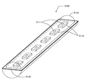
図1は、本実施例のLEDランプ構造体の構成の一例を示す図である。本図に示すLEDランプ構造体0100は、複数のLED素子0110(煩雑を避けるため符号は一部についてのみ示す。他図においても同様である。)を配置する基板0120と、LED素子の発光部0111(同じく符号は一部についてのみ示す。他図においても同様である。)に密着して備えられる透明レンズ0130を有する。なお、本図においては発光部からの光の照射方向が上になるように描かれている(従って、かかるLEDランプ構造体を天井に下向けに設ける場合は上方向が床面方向となる)ところ、本明細書においては、以下特に断りのない限りすべて上方向を照射方向として説明する。
FIG. 1 is a diagram illustrating an example of the configuration of the LED lamp structure according to the present embodiment. The
図1に示したLEDランプ構造体は、複数のLED素子が直列に配置された例であるが、LED素子の配置のしかたはこれに限られず様々な配置が可能である。 The LED lamp structure shown in FIG. 1 is an example in which a plurality of LED elements are arranged in series, but the arrangement of the LED elements is not limited to this, and various arrangements are possible.
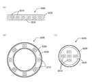
図2は、本実施例のLEDランプ構造体におけるLED素子の配置の一例を示す平面図である。(a)は、複数のLED素子を直列に配置したものであり、かかる配置を有するLEDランプ構造体としては、図1と同様の形状のものや、後述する従来型の直管型蛍光灯に代替可能な直管蛍光灯型のLEDランプ構造体が考えられる。本図ではLED素子はほぼ一直線に配置されているが、ジグザグに配置されていてもよい。また、本図ではLED素子は一列のみ配置されているが、複数列配置されていてもよい。(b)は、複数のLED素子を環形の基板上に配置したものであり、かかる配置を有するLEDランプ構造体としては、例えば従来型の環形蛍光灯と同様の形状のLEDランプ構造体が考えられる。ほぼ同心円周上に配置されていなくてもよい点、二重以上の円周上に配置されていてもよい点は(a)の場合と同様である。(c)は、複数のLED素子を略円形の基板上に配置したものであり、かかる配置を有するLEDランプ構造体としては、例えば電球型のLEDランプ構造体が考えられる。 FIG. 2 is a plan view showing an example of the arrangement of LED elements in the LED lamp structure of the present embodiment. (A) is one in which a plurality of LED elements are arranged in series. As an LED lamp structure having such an arrangement, the LED lamp structure having the same shape as in FIG. 1 or a conventional straight tube fluorescent lamp described later is used. An alternative straight tube fluorescent lamp type LED lamp structure is conceivable. In this figure, the LED elements are arranged in a substantially straight line, but may be arranged in a zigzag manner. Moreover, although only one row of LED elements is arranged in this figure, a plurality of rows may be arranged. (B) shows a configuration in which a plurality of LED elements are arranged on a ring-shaped substrate. As an LED lamp structure having such an arrangement, for example, an LED lamp structure having the same shape as a conventional ring-shaped fluorescent lamp is considered. It is done. The point which does not need to be arrange | positioned on the substantially concentric circumference and the point which may be arrange | positioned on the circumference | surroundings more than double are the same as that of the case of (a). (C) is one in which a plurality of LED elements are arranged on a substantially circular substrate. As an LED lamp structure having such an arrangement, for example, a bulb-type LED lamp structure is conceivable.
なお、本図の例では、LED素子の光照射方向はすべて同じ方向であるが、LED素子の照射方向は互いに異なっていてもよい。例えば、(a)に示したような直列型のLEDランプ構造体においてLED素子の列を三列とし、両端の二列はそれぞれ外側に向かって斜め上方向を照射する向きに配置されるようにしたものなどであってもよい。 In the example of this figure, the light irradiation directions of the LED elements are all the same direction, but the irradiation directions of the LED elements may be different from each other. For example, in the series-type LED lamp structure as shown in FIG. 4A, the LED element rows are arranged in three rows, and the two rows at both ends are arranged so as to irradiate obliquely upward toward the outside. It may be what was done.
(基板) (substrate)
「基板」はその上に複数のLED素子が配置するためのセラミックス製などの板状部材である。LED素子の個数は複数であればいくつであってもよい。図1、図2の例では説明の簡単のために5〜8個程度の例で示したが、実際にはより多くのLED素子が配置されたものが想定される。 The “substrate” is a plate-like member made of ceramics on which a plurality of LED elements are arranged. The number of LED elements may be any number as long as it is plural. In the example of FIG. 1 and FIG. 2, about 5 to 8 examples are shown for simplicity of explanation, but it is assumed that more LED elements are actually arranged.
(透明レンズ:全般) (Transparent lens: General)
「透明レンズ」は、光学的に光の向きを所望の方向に向けることを目的とした透明の部材である。例えば凸レンズの場合であれば、発光部からの光を集束させて、透明レンズ通過後における単位面積当たり照射光束量(照度)を、透明レンズを備えない場合に比べて増加させることが可能となる。凹レンズの場合であれば、発光部からの光を発散させてより広い範囲に光が行き渡るようにすることが可能となる。従って、天井に下向けに設けられたLEDランプの光で床面などを明るく照らす場合のように特定の方向における照度を増すことを目的とする場合は、透明レンズは凸レンズであることが望ましい。一方、部屋全体を明るく照らすことを目的とする場合は凹レンズとすることが望ましい。あるいは用途によっては凸レンズと凹レンズとを部分的に融合したような複合型のレンズであってもよい。 The “transparent lens” is a transparent member intended to optically direct the direction of light in a desired direction. For example, in the case of a convex lens, it is possible to focus the light from the light emitting part and increase the amount of irradiating light flux (illuminance) per unit area after passing through the transparent lens compared to the case where no transparent lens is provided. . In the case of a concave lens, it is possible to diverge the light from the light emitting portion so that the light is spread over a wider range. Therefore, when the objective is to increase the illuminance in a specific direction, such as when the floor surface or the like is illuminated brightly with the light of an LED lamp provided downward on the ceiling, the transparent lens is preferably a convex lens. On the other hand, it is desirable to use a concave lens for the purpose of brightly illuminating the entire room. Alternatively, a compound lens in which a convex lens and a concave lens are partially fused may be used depending on applications.
また、透明レンズの形状や厚みを変化させることで透明レンズの焦点距離を調節することなどが可能となり、光の集束や拡散の程度を変化させることができる。即ち、透明レンズの形状や厚みは達成しようとする光の集束や拡散の程度に応じて適切に設計される事項である。 In addition, the focal length of the transparent lens can be adjusted by changing the shape and thickness of the transparent lens, and the degree of light focusing and diffusion can be changed. That is, the shape and thickness of the transparent lens are matters that are appropriately designed according to the degree of light focusing and diffusion to be achieved.
「透明」には、無色透明、有色透明のどちらも含まれる。有色とは、例えば赤、青、緑、黄緑、黄色、だいだいなどである。また色も複合していてもよい。例えばレンズの半分は赤色、もう半分は緑色などである。さらにレンズの材料中の全部又は一部に蛍光材料や蓄光性材料を混ぜてもよい。これにより多様な色を実現できたり、通電終了後でも光を放ち続けたりするなどが可能となる。 "Transparent" includes both colorless and transparent and colored and transparent. The colored means, for example, red, blue, green, yellowish green, yellow, or the like. The colors may also be combined. For example, half of the lens is red and the other half is green. Further, a fluorescent material or a phosphorescent material may be mixed in all or part of the lens material. As a result, various colors can be realized, and it is possible to continue emitting light even after energization.
透明レンズの材質としては、比較的硬いガラスや、ポリメチルメタクリレート、ジアリルカーボネイト、ポリカーボネイトなどの硬質の透明樹脂などが挙げられる。このほか、柔軟性がある透明ゲル状材料を利用したレンズであってもよい。透明ゲル状材料を利用したレンズについては改めて後述する。また硬質材料と軟質材料とが部分的に複合した部品を用いてもよい。 Examples of the material of the transparent lens include relatively hard glass and hard transparent resins such as polymethyl methacrylate, diallyl carbonate, and polycarbonate. In addition, a lens using a flexible transparent gel material may be used. A lens using a transparent gel material will be described later. A part in which a hard material and a soft material are partially combined may be used.
透明レンズを複数のLED素子上に配置する際には、図1、図2に示した例のように複数のLED素子の全部を一個のレンズでまとめて覆うようにしてもよいし、一部の複数個のLED素子を一個のレンズで覆うようにしてもよい。あるいは、個々のLED素子を別々の透明レンズが覆う形でLED素子と同数の透明レンズが備えられるようにしてもよい。 When the transparent lens is arranged on the plurality of LED elements, all of the plurality of LED elements may be collectively covered with one lens as in the example shown in FIGS. The plurality of LED elements may be covered with a single lens. Alternatively, the same number of transparent lenses as the LED elements may be provided so that the individual LED elements are covered by separate transparent lenses.
(透明レンズ:透明ゲル状材料を利用したレンズ) (Transparent lens: lens using transparent gel material)
透明レンズは透明ゲル状材料を利用したレンズであってもよい。透明ゲル状材料としては、シリコン樹脂や、シリコン樹脂を基本としてこれに副次的な材料を混ぜたものが挙げられる。またアクリルゲルなどであってもよい。 The transparent lens may be a lens using a transparent gel material. Examples of the transparent gel-like material include silicon resin and silicon resin as a basic material mixed with a secondary material. Moreover, an acrylic gel etc. may be sufficient.
さらに、透明ゲル状材料からなる透明レンズの表面は透明プラスティック材料から構成されていてもよい。特に、透明ゲル材料からなる透明レンズが外部にむき出しになっている場合には、レンズ表面が柔らかく粘着性があるため、傷がついたりほこりが付着したりするおそれがあることから、これを防止するためにこのように構成されることが望ましい。具体的には、例えばレンズ表面をシリコン系塗料によってコーティングすることが考えられる。 Furthermore, the surface of the transparent lens made of a transparent gel material may be made of a transparent plastic material. In particular, when a transparent lens made of a transparent gel material is exposed to the outside, the lens surface is soft and sticky, which may cause scratches or dust to adhere. Therefore, it is desirable to be configured in this way. Specifically, for example, it is conceivable to coat the lens surface with a silicon-based paint.
(透明レンズ:発光部に密着させるための構成) (Transparent lens: A structure for contacting the light emitting part)
本実施例の透明レンズはLED素子の発光部に密着して備えられる点に特徴がある。透明レンズを発光部に密着させる目的は、LED素子の発光部から発せられる光が他の物質(空気)を介することなくレンズに入射するようにすることで、光の伝達効率の低下を防ぐことにある。ここで「密着」とは、透明レンズを発光部に対して隙間が生じないように付着させることをいう。ただし、隙間が生じないとは言っても、透明レンズと発光部の間に不可避的に空間が生じることまで排除するものではなく、上記の密着の目的の達成を阻害しない範囲であれば、不可避的な若干の空間が生じるものも本実施例にいう「密着」に含まれる。なお、「LED素子の発光部」は、LED素子において陽極と陰極に電圧を印加することで発光する部分をいう。 The transparent lens of this embodiment is characterized in that it is provided in close contact with the light emitting portion of the LED element. The purpose of attaching the transparent lens to the light emitting part is to prevent the light emitted from the light emitting part of the LED element from entering the lens without passing through other substances (air), thereby preventing a decrease in light transmission efficiency. It is in. Here, “close contact” refers to attaching the transparent lens to the light emitting portion so that no gap is generated. However, even if a gap does not occur, it does not exclude the unavoidable space between the transparent lens and the light emitting part. Such a slight space is also included in the “contact” in this embodiment. The “light emitting part of the LED element” means a part that emits light by applying a voltage to the anode and the cathode in the LED element.
透明レンズをLED素子の発光部に密着させるための構成としては、以下のような方法によるものが考えられる。透明レンズが比較的硬いガラスや硬質のプラスティックの場合は、例えば、予めLED素子の形状にぴったり合うように成形された透明レンズを被せるようにすればよい。あるいは、概ねLED素子の形状に合わせて成形された透明レンズを被せるとともに、透明レンズとLED素子の中間にゲル状の材料を用いた平板状の部材(以下「ゲル中間材」という。)を挟み込んでぴったり圧着させることで、LED基板の発光部と透明レンズとの間に生じる隙間をなくすようにしてもよい。この場合にゲル中間材のLED素子との当接部分は平面的なものであってもよいがLEDチップの高差分程度凹となっていてもよい。このようにすることでさらにLEDチップの発光部分とゲル中間材との密着度を向上させることができるとともに、透明レンズとの当接面にまでLEDチップの凹凸が反映することがなく、ゲル中間材の透明レンズ側の表面を平面にできるというメリットがある。 As a configuration for bringing the transparent lens into close contact with the light emitting portion of the LED element, the following method can be considered. In the case where the transparent lens is relatively hard glass or hard plastic, for example, a transparent lens that has been molded in advance so as to exactly match the shape of the LED element may be covered. Or while covering the transparent lens shape | molded according to the shape of the LED element substantially, the flat member (henceforth "gel intermediate material") which used the gel-like material between the transparent lens and the LED element is inserted | pinched. It is also possible to eliminate a gap generated between the light emitting portion of the LED substrate and the transparent lens by being tightly crimped with. In this case, the contact portion of the gel intermediate material with the LED element may be planar, or may be recessed to the extent that the LED chip has a high difference. In this way, the degree of adhesion between the light emitting portion of the LED chip and the gel intermediate material can be further improved, and the unevenness of the LED chip is not reflected on the contact surface with the transparent lens. There is an advantage that the surface on the transparent lens side of the material can be flat.
なお、かかるゲル中間材を挟み込むことの副次的な目的として、LED素子や基板などで発生する熱を所望の方向に排熱するコントロールを可能にするということも挙げられる。さらに、ゲル中間材の厚みを調節することで、発光部から発せされた光が透明レンズを通過後に集束する位置を変更して、実質的に透明レンズの焦点距離を調節することなども可能となる。 In addition, as a secondary purpose of sandwiching such a gel intermediate material, it is possible to control to exhaust heat generated in an LED element or a substrate in a desired direction. In addition, by adjusting the thickness of the gel intermediate material, it is possible to change the position where the light emitted from the light emitting part converges after passing through the transparent lens, thereby substantially adjusting the focal length of the transparent lens, etc. Become.
透明レンズが柔軟性を有する透明ゲル状材料の場合は、例えば、発光部に透明もしくは半透明の硬質プラスティック製のキャップ(カバー)を伏せるようにして被せ、その中に透明ゲル状材料を隙間なく充填することでレンズを形成するようにすればよい。あるいは、レンズの形に形成した透明ゲル状材料の表面に透明な硬質プラスティック製の膜をコーティングするようにしてもよい。 In the case where the transparent lens is a flexible transparent gel-like material, for example, a transparent or translucent hard plastic cap (cover) is covered on the light emitting part so that the transparent gel-like material is covered without any gaps. A lens may be formed by filling. Alternatively, a transparent hard plastic film may be coated on the surface of the transparent gel material formed in the shape of a lens.
なお、透明レンズは複眼レンズであってもよい。かかる例については、別の実施例にて後述する。 The transparent lens may be a compound eye lens. Such an example will be described later in another embodiment.
(電極を有する例) (Example with electrodes)
本実施例のLEDランプ構造体は、電源からの電力を灯具のソケットから受けてLED素子に給電するための電極を備えていてもよい。この電極は、従来の直管蛍光灯と互換性を持たせるために従来の直管蛍光灯具のソケットに取り付け可能なものであってもよいし、かかる互換性を有しないものであってもよい。前者については次実施例にて詳述する。後者の従来の直管蛍光灯と互換性を有しないものの例としては、社団法人日本電球工業会が2010年10月に制定した規格である「L型口金付き直管形LEDランプシステム(JEL801)」に基づく口金が挙げられる(非特許文献1「家電Watch 2010年10月19日付記事『日本電球工業会、直管形LEDランプの規格を制定』(URL:http://kaden.watch.impress.co.jp/docs/news/20101019_401018.html)参照」。 The LED lamp structure of the present embodiment may include an electrode for receiving power from a power source from a lamp socket and supplying power to the LED element. This electrode may be attachable to a socket of a conventional straight tube fluorescent lamp in order to be compatible with a conventional straight tube fluorescent lamp, or may not have such compatibility. . The former will be described in detail in the next embodiment. As an example of the latter, which is not compatible with the conventional straight tube fluorescent lamp, “Standard type LED lamp system with L-type cap (JEL801)” which is a standard established in October 2010 by the Japan Light Bulb Industry Association (Non-Patent Document 1, “Home Appliance Watch October 19th 2010 Article“ Japan Light Bulb Industry Association Establishes Standards for Straight Tube LED Lamps ”) (URL: http: //kaden.watch.impless .Co.jp / docs / news / 20101019_401018.html) ".
図9は、非特許文献1に掲載されているL型口金(端子)を備えるLEDランプ構造体の形状の一例を示す。本例のLEDランプ構造体0900が備える端子は給電側の端子とアース側の端子で異なる形状を有している。(a)に示す給電側の端子09041は略L字形の一対の板状部材からなる。(b)は、(a)の概ね破線円0902の位置を矢印B方向に見た図であり、本図に現れるアース側の端子0942は、一本の棒状部材の先端に略楕円柱状の部材を取り付けた形状を有する。
FIG. 9 shows an example of the shape of an LED lamp structure including an L-shaped base (terminal) described in Non-Patent Document 1. The terminals included in the LED lamp structure 0900 of this example have different shapes for the power supply side terminal and the ground side terminal. The terminal 09041 on the power feeding side shown in (a) is composed of a pair of substantially L-shaped plate members. (B) is the figure which looked at the position of the substantially broken-
(その他) (Other)
透明レンズは、全体がガラス管などのカバーの内部に収納されていてもよいし、外部にむき出しになっていてもよい。前者の典型は、次実施例で述べるような、LEDランプ構造体が従来の直管蛍光灯と同一の形状を有し、管体の中にLED素子を配置した基板および透明レンズが収納されたものである。この場合において透明レンズが透明ゲル状材料のときは、基板上の管体内の約半分を占める空間に透明ゲル状材料が充填されたものが典型である。なお、従来の直管蛍光灯と同一の形状を有するLEDランプ構造体については次実施例で詳述する。 The entire transparent lens may be housed inside a cover such as a glass tube, or may be exposed to the outside. A typical example of the former is that the LED lamp structure has the same shape as a conventional straight tube fluorescent lamp as described in the next embodiment, and a substrate on which the LED element is arranged and a transparent lens are accommodated in the tube. Is. In this case, when the transparent lens is a transparent gel-like material, typically, a transparent gel-like material is filled in a space that occupies about half of the tube on the substrate. The LED lamp structure having the same shape as a conventional straight tube fluorescent lamp will be described in detail in the next embodiment.
<効果> <Effect>
本実施例の発明により、LEDランプの発光部と床などの照射面との間にある程度距離があっても十分な明るさが得られるようにしたり、また部屋全体を明るく照らしたりすることが可能なLEDランプ構造体を提供することが可能となる。 With the invention of this embodiment, it is possible to obtain sufficient brightness even if there is a certain distance between the light emitting part of the LED lamp and the irradiation surface such as the floor, or to illuminate the entire room brightly It becomes possible to provide a simple LED lamp structure.
<概要> <Overview>
本実施例のLEDランプ構造体は、基本的に実施例1のLEDランプ構造体と共通するが、従来の直管蛍光灯具のソケットに取り付け可能な電極を有し、前記基板が両端電極間に配置されたことを特徴とする。これは、実施例1のLEDランプ構造体の特徴である照射面との間にある程度距離があっても十分な明るさが得られるとか、部屋全体を明るく照らすことができるといった点を生かしつつ、さらに従来の直管型蛍光灯との互換性を持たせることで、取換え工事を簡易に行えるようにし、また構成を工夫することにより従来の直管蛍光灯からLED照明に変えたときの違和感をなくすことを目的とするものである。 The LED lamp structure of the present embodiment is basically the same as the LED lamp structure of Embodiment 1, but has an electrode that can be attached to the socket of a conventional straight tube fluorescent lamp, and the substrate is between both end electrodes. It is arranged. While taking advantage of the fact that sufficient brightness can be obtained even if there is a certain distance between the irradiation surface, which is a feature of the LED lamp structure of Example 1, or that the entire room can be illuminated brightly, In addition, by providing compatibility with conventional straight tube fluorescent lamps, the replacement work can be performed easily, and by changing the configuration, the sense of incongruity when changing from conventional straight tube fluorescent lamps to LED lighting is improved. The purpose is to eliminate.
<構成> <Configuration>
図3は、本実施例のLEDランプ構造体の構成の一例を示す図である。本実施例のLEDランプ構造体の構成は基本的に実施例1のLEDランプ構造体の構成と共通する。従って、本図に示すLEDランプ構造体0300も、複数のLED素子0310を配置する基板0320と、LED素子の発光部0311に密着して備えられる透明レンズ0330を有する。さらに、本図に示すLEDランプ構造体は、両端に従来の直管蛍光灯具のソケット(図示されない)に取り付け可能な電極0340を有し、前記基板が両端電極間に配置される。以下、電極の構成、および本実施例のLEDランプ構造体における透明レンズの配置例について説明する。その余の構成は実施例1と同様であるので説明を省略する。
FIG. 3 is a diagram illustrating an example of the configuration of the LED lamp structure according to the present embodiment. The configuration of the LED lamp structure of the present embodiment is basically the same as the configuration of the LED lamp structure of the first embodiment. Therefore, the LED lamp structure 0300 shown in this drawing also includes a
(電極) (electrode)
本実施例のLEDランプ構造体が有する「電極」は、電源からの電力を従来の直管蛍光灯具のソケットから受けてLED素子に給電するためのものであり、このため従来の直管蛍光灯具のソケットに取り付け可能に構成されている。即ち、本実施例の電極は従来の直管蛍光灯の口金に備えられるピンに相当するものであり、これと同一の形状、寸法を有する。「従来の直管蛍光灯」とは、JISC7617−2「直管蛍光ランプ−第2部:性能規定」の2.3.1「データシートのリスト」に規定された直管蛍光ランプを指す。また、当該規格において、当該ランプの口金はJISC7709−1「電球類の口金・受金及びそれらのゲージ並びに互換性・安全性 第1部 口金」に規定された規格に適合すべき旨が定められている。例えば、管径16mmの直管蛍光灯にはG−5口金(ピン間隔約5mm)が、管径25mm、28mm、32.5mm、38mmの直管蛍光灯にはG−13口金(ピン間隔約13mm)が用いられるところ、本実施例のLEDランプ構造体の電極はこれらの口金に備えられるピンと同一の形状・寸法を有する。 The “electrode” included in the LED lamp structure of the present embodiment is for receiving power from a power source from a socket of a conventional straight tube fluorescent lamp and supplying power to the LED element. For this reason, a conventional straight tube fluorescent lamp is provided. It is configured to be attachable to the socket. That is, the electrode of the present embodiment corresponds to a pin provided in a base of a conventional straight tube fluorescent lamp, and has the same shape and size as this. “Conventional straight tube fluorescent lamp” refers to a straight tube fluorescent lamp defined in 2.3.1 “List of data sheets” of JISC7617-2 “Straight tube fluorescent lamp—Part 2: Performance specification”. The standard also states that the cap of the lamp should comply with the standard specified in JIS C7709-1, “Caps and Receivers of Light Bulbs and Their Gauges and Compatibility / Safety Part 1”. ing. For example, a straight tube fluorescent lamp with a tube diameter of 16 mm has a G-5 base (pin spacing of about 5 mm), and a straight tube fluorescent lamp with a tube diameter of 25 mm, 28 mm, 32.5 mm, and 38 mm has a G-13 base (pin spacing of about 13 mm), the electrodes of the LED lamp structure of the present embodiment have the same shape and dimensions as the pins provided in these caps.
また、本実施例のLEDランプ構造体の電極が従来の直管蛍光灯具のソケットに取り付け可能であることから、必然的に本実施例のLEDランプ構造体の寸法も従来の直管蛍光灯具に取り付け可能な寸法に規制される。一例を挙げれば、G−13口金に対応するソケットに取り付け可能ないわゆる40W形直管蛍光灯(管径32.5mm)の管長は1,198mmであり、いわゆる110W形直管蛍光灯(管径38mm)の管長は2,367mmであるので、本実施例のLEDランプ構造体の寸法もこれらの寸法と同じ寸法となる。 In addition, since the electrode of the LED lamp structure of this embodiment can be attached to the socket of a conventional straight tube fluorescent lamp, the dimensions of the LED lamp structure of this embodiment are inevitably the same as those of the conventional straight tube fluorescent lamp. It is restricted to the size that can be attached. For example, the tube length of a so-called 40W type straight tube fluorescent lamp (tube diameter 32.5 mm) that can be attached to a socket corresponding to the G-13 base is 1,198 mm, and the so-called 110W type straight tube fluorescent lamp (tube diameter) The tube length of 38 mm) is 2,367 mm, and therefore the dimensions of the LED lamp structure of this embodiment are the same as these dimensions.
(本実施例のLEDランプ構造体における透明レンズの配置例) (Example of arrangement of transparent lens in LED lamp structure of this example)
本実施例のLEDランプ構造体においては、基板が両端電極間に配置される。そこで、当該基板上に配置される複数のLED素子は、当該両端電極間に直列的に配置される。このため、仮にこれら複数のLED素子の発光部に密着して備えられる透明レンズを一個の透明レンズとする場合には、当該レンズは例えば蒲鉾形状をした細長いレンズとなる。 In the LED lamp structure of the present embodiment, the substrate is disposed between the both end electrodes. Therefore, the plurality of LED elements arranged on the substrate are arranged in series between the both end electrodes. For this reason, if the transparent lens provided in close contact with the light emitting portions of the plurality of LED elements is a single transparent lens, the lens is, for example, an elongated lens having a bowl shape.
図4は、本実施例のLEDランプ構造体における透明レンズの配置の一例を示す図であり、図3のA−A線垂直断面図である。即ち、本例の配置は、図3に示したものと同一であり、斜線で示した部分が透明レンズ0430である。本図の例のLEDランプ構造体は、従来の直管蛍光灯の管体(蛍光管本体)の上側の略半分に相当する部分(天井に下向きに取り付けた場合は床面側の略半分に相当する部分)がないため、見た目の印象が従来の直管蛍光灯とは相当異なったものとなり得る。
FIG. 4 is a diagram showing an example of the arrangement of the transparent lenses in the LED lamp structure of the present embodiment, and is a vertical cross-sectional view taken along the line AA of FIG. That is, the arrangement of this example is the same as that shown in FIG. 3, and the shaded portion is the
一方、本実施例のLEDランプ構造体は、従来の直管蛍光灯と同じ形状・寸法の管体を有するものであってもよい。このように構成することで、従来の照明からLED照明に変えたときに部屋の雰囲気が変わらないようにすることができる。 On the other hand, the LED lamp structure of the present embodiment may have a tube body having the same shape and size as a conventional straight tube fluorescent lamp. By comprising in this way, the atmosphere of a room can be prevented from changing when it changes from conventional illumination to LED illumination.
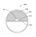
図5は、本実施例のLEDランプ構造体における透明レンズの配置の別の一例を図4と同様の垂直断面図で示したものである。本例のLEDランプ構造体0500は直管蛍光灯と同じ形状・寸法の管体0501を有し、管体内に基板0520、複数のLED素子0510(発光部0511を有する)および透明レンズ0530が備えられている。この場合、LED素子の発光部から発せられた光が管体内で減衰することがないようにするため、本図の例のように管体0501内の基板より上側の空間に透明レンズ(好適には透明ゲル状材料からなるレンズ)が隙間なく充填されていることが望ましい。
FIG. 5 is a vertical sectional view similar to FIG. 4 showing another example of the arrangement of the transparent lenses in the LED lamp structure of the present embodiment. The
図6も、本実施例のLEDランプ構造体における透明レンズの配置のさらに別の一例を図4と同様の垂直断面図で示したものである。本図の例は、図4と同様従来の直管蛍光灯の管体の上側の略半分に相当する部分を欠くものであるが、図4の例と異なり、透明レンズが当該管体とほぼ同一の形状を有するものである。この場合の透明レンズには硬質のガラスやプラスティックを用いればよい。さらに、従来の直管蛍光灯との違和感をなくすためにレンズ表面を半透明の素材でコーティングしてもよい。あるいは、透明レンズに透明ゲル状材料からなるレンズを用いるとともに、レンズ表面を透明または半透明の素材でコーティングしてもよい。 FIG. 6 also shows another example of the arrangement of the transparent lenses in the LED lamp structure of the present embodiment in a vertical sectional view similar to FIG. The example of this figure lacks a portion corresponding to approximately the upper half of the tube of a conventional straight tube fluorescent lamp as in FIG. 4, but unlike the example of FIG. 4, the transparent lens is substantially the same as the tube. It has the same shape. In this case, the transparent lens may be made of hard glass or plastic. Further, the lens surface may be coated with a translucent material in order to eliminate the uncomfortable feeling with the conventional straight tube fluorescent lamp. Alternatively, a lens made of a transparent gel material may be used for the transparent lens, and the lens surface may be coated with a transparent or translucent material.
<効果> <Effect>
本実施例の発明により、実施例1のLEDランプ構造体の特徴を生かしつつ、さらに従来の直管型蛍光灯との互換性を持たせることで、取換え工事を簡易に行えるようにすることができる。また構成を工夫することにより従来の直管蛍光灯からLED照明に変えたときの違和感をなくすことが可能となる。 By making use of the characteristics of the LED lamp structure of the first embodiment by the invention of the present embodiment, and making it compatible with the conventional straight tube fluorescent lamp, the replacement work can be performed easily. Can do. Further, by devising the configuration, it is possible to eliminate the uncomfortable feeling when the conventional straight tube fluorescent lamp is changed to LED illumination.
<概要> <Overview>
本実施例のLEDランプ構造体は、基本的に実施例1または2のLEDランプ構造体と共通するが、透明レンズが複眼レンズであることを特徴とする。これは、レンズ素子の数を増やすことで光の集束・拡散をより多様な態様で実現することを可能にすることを目的とする。また、複眼レンズを用いることでレンズの厚みや体積を減らして材料費の節減や軽量化を図ることも可能となる。 The LED lamp structure of the present embodiment is basically the same as the LED lamp structure of Embodiment 1 or 2, but the transparent lens is a compound eye lens. The purpose of this is to increase the number of lens elements so that light focusing and diffusion can be realized in more various modes. Further, by using a compound eye lens, it is possible to reduce the thickness and volume of the lens, thereby reducing the material cost and reducing the weight.
<構成> <Configuration>
本実施例のLEDランプ構造体の構成は基本的に実施例1または2のLEDランプ構造体の構成と共通する。即ち、本例のLEDランプ構造体も、複数のLED素子を配置する基板と、LED素子の発光部に密着して備えられる透明レンズを有する。ただし、本実施例の透明レンズは複眼レンズである。以下、複眼レンズの構成について説明する。その余の構成は実施例1または2と同様であるので説明を省略する。 The configuration of the LED lamp structure of the present embodiment is basically the same as the configuration of the LED lamp structure of Embodiment 1 or 2. That is, the LED lamp structure of this example also includes a substrate on which a plurality of LED elements are arranged and a transparent lens that is provided in close contact with the light emitting portion of the LED elements. However, the transparent lens of the present embodiment is a compound eye lens. Hereinafter, the configuration of the compound eye lens will be described. Since the rest of the configuration is the same as in the first or second embodiment, the description thereof is omitted.
(複眼レンズ) (Compound eye lens)
本実施例における「複眼レンズ」には、複数のレンズ素子を有するレンズが広く含まれる。 The “compound eye lens” in this embodiment includes a wide range of lenses having a plurality of lens elements.
図7は、複眼レンズである透明レンズの一例を示す図である。本図に示す複眼レンズはいわゆるフライアイレンズの例であって、本例では同一の半球形を有する複数のレンズ素子を縦横に配列したものである。なお、レンズ素子の形状はこの例のほかに略四角柱、略六角柱などの多角柱形状などであってもよく、また、透明レンズがフレネルレンズであってもよい。また、すべてのレンズ素子の形状が同一である必要はなく、異なる形状が混在したものであってもよい。 FIG. 7 is a diagram illustrating an example of a transparent lens that is a compound eye lens. The compound eye lens shown in this figure is an example of a so-called fly-eye lens, and in this example, a plurality of lens elements having the same hemispherical shape are arranged vertically and horizontally. In addition to this example, the shape of the lens element may be a polygonal column shape such as a substantially quadrangular prism or a substantially hexagonal column, and the transparent lens may be a Fresnel lens. Further, it is not necessary for all lens elements to have the same shape, and different shapes may be mixed.
図8は、複眼レンズである透明レンズの別の一例を示す図である。本図に示す複眼レンズは蒲鉾型のレンズを複数列並べたものである。本実施例における複眼レンズは上述のように複数のレンズ素子を有するレンズが広く含まれるから、このようなものも含まれる。 FIG. 8 is a diagram illustrating another example of a transparent lens that is a compound eye lens. The compound eye lens shown in this figure is a lens in which a plurality of bowl-shaped lenses are arranged. Since the compound eye lens in the present embodiment widely includes lenses having a plurality of lens elements as described above, such a lens is also included.
本実施例のLEDランプ構造体によれば、このようにレンズ素子の数を増やすことで光の集束・拡散をより多様な態様で実現することができる。このため、例えば実施例2のLEDランプ構造体(従来の直管蛍光灯具のソケットに取り付け可能な電極を有するもの)に本実施例の複眼レンズを適用した場合には、透明レンズに半透明のコーティングをしないままであっても個々のLED素子の形状が明確には見えづらくなることから、従来の直管蛍光灯からLED照明に変えたときの違和感を減らすことが可能となる。また、特に複眼レンズをフレネルレンズにした場合をはじめとして、レンズの厚みや体積を減らして材料費の節減や軽量化を図ることも可能となる。 According to the LED lamp structure of the present embodiment, it is possible to realize light focusing / diffusion in various modes by increasing the number of lens elements in this way. Therefore, for example, when the compound eye lens of the present embodiment is applied to the LED lamp structure of the second embodiment (having electrodes that can be attached to a socket of a conventional straight tube fluorescent lamp), the transparent lens is translucent. Since the shape of each LED element is not clearly seen even without being coated, it is possible to reduce a sense of incongruity when the conventional straight tube fluorescent lamp is changed to LED illumination. In addition, particularly when the compound eye lens is a Fresnel lens, the thickness and volume of the lens can be reduced to reduce the material cost and reduce the weight.
<効果> <Effect>
本実施例の発明により、レンズ素子の数を増やすことで光の集束・拡散をより多様な態様で実現することを可能にすることが可能となる。また、複眼レンズを用いることでレンズの厚みや体積を減らして材料費の節減や軽量化を図ることも可能となる。 According to the invention of this embodiment, it is possible to realize light focusing / diffusion in more various modes by increasing the number of lens elements. Further, by using a compound eye lens, it is possible to reduce the thickness and volume of the lens, thereby reducing the material cost and reducing the weight.
Claims (5)
前記LED素子の発光部に密着して備えられる透明レンズと、
を有するLEDランプ構造体。 A substrate on which a plurality of LED elements are arranged;
A transparent lens provided in close contact with the light emitting portion of the LED element;
LED lamp structure having
前記基板は両端電極間に配置された請求項1に記載のLEDランプ構造体。 It has an electrode that can be attached to the socket of a conventional straight tube fluorescent lamp,
The LED lamp structure according to claim 1, wherein the substrate is disposed between both end electrodes.
Priority Applications (1)
| Application Number | Priority Date | Filing Date | Title |
|---|---|---|---|
| JP2010254081A JP2012104445A (en) | 2010-11-12 | 2010-11-12 | Led lamp structure |
Applications Claiming Priority (1)
| Application Number | Priority Date | Filing Date | Title |
|---|---|---|---|
| JP2010254081A JP2012104445A (en) | 2010-11-12 | 2010-11-12 | Led lamp structure |
Publications (1)
| Publication Number | Publication Date |
|---|---|
| JP2012104445A true JP2012104445A (en) | 2012-05-31 |
Family
ID=46394585
Family Applications (1)
| Application Number | Title | Priority Date | Filing Date |
|---|---|---|---|
| JP2010254081A Pending JP2012104445A (en) | 2010-11-12 | 2010-11-12 | Led lamp structure |
Country Status (1)
| Country | Link |
|---|---|
| JP (1) | JP2012104445A (en) |
Cited By (2)
| Publication number | Priority date | Publication date | Assignee | Title |
|---|---|---|---|---|
| JP5887519B2 (en) * | 2012-07-05 | 2016-03-16 | パナソニックIpマネジメント株式会社 | Lamp and lighting device |
| US9568156B2 (en) | 2013-02-01 | 2017-02-14 | Samsung Electronics Co., Ltd. | Light source module and lighting device having the same |
Citations (6)
| Publication number | Priority date | Publication date | Assignee | Title |
|---|---|---|---|---|
| JP2005085639A (en) * | 2003-09-09 | 2005-03-31 | Junichi Shimada | Head-mounted led lighting device |
| JP2006013198A (en) * | 2004-06-28 | 2006-01-12 | Kyocera Corp | Package for housing light emitting element, light emitting apparatus, and illuminator |
| JP2007142474A (en) * | 2003-04-24 | 2007-06-07 | Nichia Chem Ind Ltd | Semiconductor device and method of manufacturing same |
| WO2008078791A1 (en) * | 2006-12-27 | 2008-07-03 | Showa Denko K.K. | Method of producing light emission device |
| JP2010050472A (en) * | 2001-12-29 | 2010-03-04 | Hangzhou Fuyang Xinying Electronics Co Ltd | Light emitting diode lamp, and light emitting diode traffic light |
| JP2010067367A (en) * | 2008-09-08 | 2010-03-25 | Esl:Kk | Condenser lens for led illumination device and led illumination device using the same |
-
2010
- 2010-11-12 JP JP2010254081A patent/JP2012104445A/en active Pending
Patent Citations (6)
| Publication number | Priority date | Publication date | Assignee | Title |
|---|---|---|---|---|
| JP2010050472A (en) * | 2001-12-29 | 2010-03-04 | Hangzhou Fuyang Xinying Electronics Co Ltd | Light emitting diode lamp, and light emitting diode traffic light |
| JP2007142474A (en) * | 2003-04-24 | 2007-06-07 | Nichia Chem Ind Ltd | Semiconductor device and method of manufacturing same |
| JP2005085639A (en) * | 2003-09-09 | 2005-03-31 | Junichi Shimada | Head-mounted led lighting device |
| JP2006013198A (en) * | 2004-06-28 | 2006-01-12 | Kyocera Corp | Package for housing light emitting element, light emitting apparatus, and illuminator |
| WO2008078791A1 (en) * | 2006-12-27 | 2008-07-03 | Showa Denko K.K. | Method of producing light emission device |
| JP2010067367A (en) * | 2008-09-08 | 2010-03-25 | Esl:Kk | Condenser lens for led illumination device and led illumination device using the same |
Cited By (3)
| Publication number | Priority date | Publication date | Assignee | Title |
|---|---|---|---|---|
| JP5887519B2 (en) * | 2012-07-05 | 2016-03-16 | パナソニックIpマネジメント株式会社 | Lamp and lighting device |
| JPWO2014006901A1 (en) * | 2012-07-05 | 2016-06-02 | パナソニックIpマネジメント株式会社 | Lamp and lighting device |
| US9568156B2 (en) | 2013-02-01 | 2017-02-14 | Samsung Electronics Co., Ltd. | Light source module and lighting device having the same |
Similar Documents
| Publication | Publication Date | Title |
|---|---|---|
| JP4755276B2 (en) | Light source for illumination | |
| US8322896B2 (en) | Solid-state light bulb | |
| JP3171402U (en) | Lighting device | |
| WO2010119618A1 (en) | Light emitting device and bulb-type led lamp | |
| JP5618097B2 (en) | Optical device and light emitting device including the same | |
| JP4971530B2 (en) | lamp | |
| US8696156B2 (en) | LED light bulb with light scattering optics structure | |
| JP2008159453A (en) | Light source device, and lamp having same | |
| JP2013219340A (en) | Light-emitting diode and luminaire and lighting fixture using the same | |
| JP2011034969A (en) | Lamp | |
| JP2008084990A (en) | Light-emitting apparatus and illumination appliance | |
| JP2017045951A (en) | LED module and luminaire having the same | |
| JP2011134508A (en) | Lighting fixture | |
| WO2012049803A1 (en) | Lamp | |
| JP2013171777A (en) | Lighting device | |
| TW201250170A (en) | Light emitting diode light bulbs and light emitting diode assemblies thereof | |
| JP2011054340A (en) | Lighting device | |
| JP2010251213A (en) | Light-emitting module and lighting device | |
| JP2009009870A (en) | Light source unit and compact self-ballasted lamp | |
| JP2012048950A (en) | Lamp with base and lighting fixture | |
| JP2014135233A (en) | Lighting apparatus | |
| JP2012119152A (en) | Lighting system | |
| JP2012104445A (en) | Led lamp structure | |
| JP2014102973A (en) | Lighting device | |
| JP6067246B2 (en) | Lighting device |
Legal Events
| Date | Code | Title | Description |
|---|---|---|---|
| A711 | Notification of change in applicant |
Free format text: JAPANESE INTERMEDIATE CODE: A711 Effective date: 20130219 |
|
| A521 | Written amendment |
Free format text: JAPANESE INTERMEDIATE CODE: A821 Effective date: 20130219 |
|
| RD03 | Notification of appointment of power of attorney |
Free format text: JAPANESE INTERMEDIATE CODE: A7423 Effective date: 20130606 |
|
| A621 | Written request for application examination |
Free format text: JAPANESE INTERMEDIATE CODE: A621 Effective date: 20131028 |
|
| A521 | Written amendment |
Free format text: JAPANESE INTERMEDIATE CODE: A821 Effective date: 20140501 |
|
| RD04 | Notification of resignation of power of attorney |
Free format text: JAPANESE INTERMEDIATE CODE: A7424 Effective date: 20140501 |
|
| A977 | Report on retrieval |
Free format text: JAPANESE INTERMEDIATE CODE: A971007 Effective date: 20140626 |
|
| A131 | Notification of reasons for refusal |
Free format text: JAPANESE INTERMEDIATE CODE: A131 Effective date: 20140701 |
|
| A02 | Decision of refusal |
Free format text: JAPANESE INTERMEDIATE CODE: A02 Effective date: 20141111 |