JP2014102973A - Lighting device - Google Patents

Lighting device Download PDF

Info

Publication number
JP2014102973A
JP2014102973A JP2012254092A JP2012254092A JP2014102973A JP 2014102973 A JP2014102973 A JP 2014102973A JP 2012254092 A JP2012254092 A JP 2012254092A JP 2012254092 A JP2012254092 A JP 2012254092A JP 2014102973 A JP2014102973 A JP 2014102973A
Authority
JP
Japan
Prior art keywords
optical component
light
light source
dome
bulb
Prior art date
Legal status (The legal status is an assumption and is not a legal conclusion. Google has not performed a legal analysis and makes no representation as to the accuracy of the status listed.)
Pending
Application number
JP2012254092A
Other languages
Japanese (ja)
Inventor
Masahiro Yokota
昌広 横田
Nobuo Kawamura
信雄 川村
Shusuke Morita
修介 森田
Takeshi Okawa
猛 大川
Osamu Ono
修 小野
Hideo Ota
英男 太田
Takeshi Takahashi
高橋  健
Shuzo Matsuda
秀三 松田
Koji Nishimura
孝司 西村
Current Assignee (The listed assignees may be inaccurate. Google has not performed a legal analysis and makes no representation or warranty as to the accuracy of the list.)
Toshiba Corp
Original Assignee
Toshiba Corp
Priority date (The priority date is an assumption and is not a legal conclusion. Google has not performed a legal analysis and makes no representation as to the accuracy of the date listed.)
Filing date
Publication date
Application filed by Toshiba Corp filed Critical Toshiba Corp
Priority to JP2012254092A priority Critical patent/JP2014102973A/en
Publication of JP2014102973A publication Critical patent/JP2014102973A/en
Pending legal-status Critical Current

Links

Images

Landscapes

  • Non-Portable Lighting Devices Or Systems Thereof (AREA)

Abstract

PROBLEM TO BE SOLVED: To provide a lighting device of a bulb shape which can provide high light intensity in the lateral surface direction even when using an LED light source or the like, can provide visual quality such as a filament lamp or a candle by using the LED light source.SOLUTION: A lighting device of a bulb shape includes: a substrate 2 having a top face; a light source 4 arranged on a substrate top face 2a; an optical component 5 which is formed in a dome shape having a lower end opening 5a, has the lower end opening side fixed to the substrate top face and covers a light source therewith; and a translucent cover 6 which is fixed to the substrate top face, covers the light source and the optical component therewith and has transparency. The optical component is formed such that a thickness of a wall part is smaller than the diameter of the lower end opening. The optical component has a plurality of prisms 10 disposed on the whole region of a dome inner surface to which light from the light source is made incident or a dome outer surface from which light is released to an external part, the prisms change a latitude direction angle of light beam made incident to the southern hemisphere direction of the optical component when a dome vertex T of the optical component is set as north pole and emit the light and a virtual image of the light source is formed on a position floated up from the substrate top face when being viewed through the optical component.

Description

この実施形態は、発光ダイオード(LED)のように実装された面法線方向に限られた狭い配光分布を持つ光源を用いる電球形の照明装置に関する。     This embodiment relates to a light bulb-type lighting device using a light source having a narrow light distribution that is limited in a surface normal direction and mounted like a light emitting diode (LED).

照明装置としては、白熱電球や蛍光灯が広く用いられてきたが、寿命、発光効率、水銀汚染、紫外線漏れなどの問題を抱えていた。近年、これらの問題を解消する技術として、LED光源やEL(エレクトロルミネッセンス)光源が開発され、特にLED光源は一般の照明装置への利用が加速度的に広がっている。   Incandescent light bulbs and fluorescent lamps have been widely used as lighting devices, but have problems such as lifetime, luminous efficiency, mercury contamination, and ultraviolet light leakage. In recent years, as a technique for solving these problems, LED light sources and EL (electroluminescence) light sources have been developed, and in particular, the use of LED light sources for general lighting devices is accelerating.

しかしながら、LED光源のような実装基板に実装された光源の光は、実装基板の法線方向に強く光を放出し、側面から背面にかけて光が放出されない指向性を有している。そのため、正面から背面までほぼ均一な光度分布をもつ従来の白熱電球と、LED光源を用いた電球型照明装置とを置き換えた場合、天井や壁の明るさが著しく変わってしまい、違った照度空間となってしまう。   However, light from a light source mounted on a mounting substrate such as an LED light source emits light strongly in the normal direction of the mounting substrate, and has directivity that does not emit light from the side surface to the back surface. Therefore, when a conventional incandescent light bulb with a nearly uniform light intensity distribution from the front to the back is replaced with a light bulb-type lighting device using an LED light source, the brightness of the ceiling and walls changes significantly, resulting in a different illuminance space. End up.

特に、キャンドルから生じたシャンデリア用途では、炎のように白熱電球のフィラメントが直視できる照明装置が好まれており、側面方向に点状に輝くことで周囲の散乱用アクセサリィに反射してキラキラと輝く照明装置を実現している。しかし、LED光源を用いた照明装置では、このようなフィラメント直視型の白熱電球やキャンドルと同じような見映えをもつ照明装置の実現が困難であった。   Especially for chandeliers produced from candles, lighting devices that can directly view filaments of incandescent bulbs like flames are preferred, and they shine like dots in the direction of the side surface and reflect off to the surrounding scattering accessories. A brilliant lighting device is realized. However, in an illuminating device using an LED light source, it has been difficult to realize an illuminating device having the same appearance as such a filament direct-view incandescent bulb or candle.

特許第4290887号公報Japanese Patent No. 4290887 特開2005−05546号公報JP-A-2005-05546 特許第4945690号公報Japanese Patent No. 4945690 特開2011−142060号公報JP 2011-142060 A 特開2012−64558号公報JP 2012-64558 A 特開2012−74264号公報JP 2012-74264 A 特開2012−146450号公報JP 2012-146450 A

この発明は、LED光源などを用いても、側面方向の光度が高く、フィラメントが直視される白熱電球やキャンドルのような見映えをLED光源で実現した電球形の照明装置を提供することにある。   An object of the present invention is to provide a light bulb-shaped illuminating device that realizes an appearance like an incandescent light bulb or a candle that has high luminous intensity in the lateral direction even when an LED light source is used and the filament is directly viewed, with the LED light source. .

実施形態によれば、電球形の照明装置は、頂面を有する基材と、前記基材頂面に配置された光源と、下端開口を有するドーム状に形成され、前記基材頂面に前記下端開口側が固定され前記光源を覆った光学部品と、前記基材頂面に固定され前記光源および光学部品を覆った透明性を有する透光カバーと、を備え、
前記光学部品は、壁部の肉厚が前記下端開口の径よりも小さく形成され、前記光学部品は、前記光源からの光が入射するドーム内面あるいは光を外部に放出するドーム外面の全域に設けられた複数のプリズムを有し、前記プリズムは、前記光学部品のドーム頂点を北極としたときに入射した光線の緯度方向角度を前記光学部品の南半球方向に変えて出射し、前記光学部品を通して見た際に、前記光源の虚像を前記基材頂面から浮き上がった位置に形成する。
According to the embodiment, the light bulb-shaped lighting device is formed in a dome shape having a base having a top surface, a light source disposed on the top surface of the base material, and a lower end opening, and the top surface of the base material is An optical component having a lower end opening side fixed and covering the light source, and a transparent cover having transparency that is fixed to the top surface of the base material and covers the light source and the optical component,
The optical component is formed such that the wall thickness is smaller than the diameter of the lower end opening, and the optical component is provided on the entire dome inner surface where light from the light source enters or the outer surface of the dome where light is emitted to the outside. The prism has a plurality of prisms, and the prism emits the incident light when the dome apex of the optical component is the north pole, changing the latitudinal angle of the incident light in the southern hemisphere direction of the optical component, and viewed through the optical component. In this case, a virtual image of the light source is formed at a position raised from the top surface of the base material.

図1は、第1の実施形態に係る電球形の照明装置を示す断面図。FIG. 1 is a cross-sectional view showing a light bulb-shaped illumination device according to a first embodiment. 図2は、前記電球形の照明装置を示す断面図。FIG. 2 is a cross-sectional view showing the light bulb-shaped lighting device. 図3は、前記照明装置の光線軌道を示す図。FIG. 3 is a view showing a ray trajectory of the illumination device. 図4は、第1の実施形態に係る電球形の照明装置を側面から見たときの光り方を示す図。FIG. 4 is a diagram illustrating how light is emitted when the light bulb-shaped illumination device according to the first embodiment is viewed from the side. 図5は、前記照明装置の配光分布を示す図。FIG. 5 is a view showing a light distribution of the lighting device. 図6は、第1変形例に係る電球型の照明装置を示す断面図。FIG. 6 is a cross-sectional view showing a light bulb type illumination device according to a first modification. 図7は、第2変形例に係る電球形の照明装置を示す断面図。FIG. 7 is a cross-sectional view showing a light bulb-shaped illumination device according to a second modification. 図8は、第2変形例に係る電球形の照明装置の配光分布を示す図。FIG. 8 is a diagram illustrating a light distribution of a light bulb-shaped illumination device according to a second modification. 図9は、第2変形例に係る電球形の照明装置を側面から見たときの光り方を示す図。FIG. 9 is a diagram illustrating how light is emitted when a light bulb-shaped illumination device according to a second modification is viewed from the side. 図10は、第3変形例に係る電球形の照明装置を示す断面図。FIG. 10 is a cross-sectional view showing a light bulb-shaped illumination device according to a third modification. 図11は、第3変形例に係る電球形の照明装置の配光分布を示す図。FIG. 11 is a diagram illustrating a light distribution of a light bulb-shaped lighting device according to a third modification. 図12は、第3変形例に係る電球形の照明装置を側面から見たときの光り方を示す図。FIG. 12 is a diagram illustrating how light is emitted when a light bulb-shaped illumination device according to a third modification is viewed from the side. 図13は、第2の実施形態に係る電球形の照明装置を示す断面図。FIG. 13 is a cross-sectional view showing a light bulb-shaped illumination device according to a second embodiment. 図14は、第4変形例に係る電球形の照明装置を示す断面図。FIG. 14 is a cross-sectional view showing a light bulb-shaped illumination device according to a fourth modification. 図15は、第5変形例に係る電球形の照明装置における光学部品のプリズム構造を示す斜視図。FIG. 15 is a perspective view showing a prism structure of an optical component in a light bulb-shaped illumination device according to a fifth modification. 図16は、前記第5変形例に係るプリズムの一部を拡大して示す斜視図。FIG. 16 is an enlarged perspective view showing a part of the prism according to the fifth modification.

以下、図面を参照しながら、種々の実施形態に係る照明装置について詳細に説明する。
(第1の実施形態)
図1は、第1の実施形態に係る電球形の照明装置としてLED電球1を示す断面図である。LED電球1は、中心軸Cに対して回転対称の形状をしている。
Hereinafter, illumination devices according to various embodiments will be described in detail with reference to the drawings.
(First embodiment)
FIG. 1 is a cross-sectional view showing an LED bulb 1 as a bulb-type lighting device according to the first embodiment. The LED bulb 1 has a rotationally symmetric shape with respect to the central axis C.

LED電球1は、前面に平坦な基材頂面2aを有する基材2と、基材頂面2aに実装されたLEDから成る光源4と、基材頂面2a上に配置されて光源4を覆うドーム状の光学部品5と、同じく基材頂面2aに配置されて光源4および光学部品5を覆う透明性を有する透光カバー6と、を備えている。   The LED bulb 1 includes a base material 2 having a flat base material top surface 2a on the front surface, a light source 4 composed of LEDs mounted on the base material top surface 2a, and a light source 4 arranged on the base material top surface 2a. A dome-shaped optical component 5 that covers the light source 4 and the transparent light-transmitting cover 6 that covers the light source 4 and the optical component 5 are also provided.

基材2は、金属製の筐体かつ放熱部材であり、ほぼ切頭円錐状に形成されて上端(前面)に平坦なほぼ円形の基材頂面2aを有し、基材2の下端に口金8が設けられている。光源4は、基材頂面2aの中心に配置されている。基材2の内部には、光源4を駆動する駆動回路11が収納されている。口金8から給電された電力は、駆動回路11により光源4に供給して発光させる構成となっている。基材2は、透光カバー6および口金8を保持してLED電球1の外面形状を形成するとともに、光源4の熱に対するヒートシンクと放熱板を兼ねている。   The base material 2 is a metal casing and a heat radiating member. The base material 2 is formed in a substantially truncated conical shape and has a substantially circular base top surface 2a which is flat at the upper end (front surface). A base 8 is provided. The light source 4 is disposed at the center of the base material top surface 2a. A drive circuit 11 that drives the light source 4 is housed inside the base material 2. The power supplied from the base 8 is supplied to the light source 4 by the drive circuit 11 to emit light. The base material 2 holds the translucent cover 6 and the base 8 to form the outer shape of the LED bulb 1 and also serves as a heat sink and a heat sink for the heat of the light source 4.

透光カバー6は、透明樹脂で円形の下端開口6aを有する球状に形成されている。透光カバー6は、その下端側が基材頂面2aの周縁部に固定され、光源4および光学部品5を覆っている。   The translucent cover 6 is formed in a spherical shape having a circular lower end opening 6a with a transparent resin. The translucent cover 6 has a lower end fixed to the peripheral edge of the base material top surface 2 a and covers the light source 4 and the optical component 5.

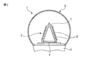
ドーム状の光学部品5は、透明性を有する材料で、例えば、三角錐状に縦長に形成され、円形の下端開口5aと、中心軸C上に位置するドーム頂点Tと、を有している。すなわち、光学部品5は、中心軸Cに沿った高さが下端開口5aの径よりも大きい、縦長に形成されている。そして、光学部品5は、下端開口5a側の下端を光源4の周囲で基材頂面2aに固定することにより、中心軸Cと同軸的に配置され、更に、光源4を覆っている。   The dome-shaped optical component 5 is made of a material having transparency, and is formed in a vertically long triangular pyramid shape, for example, and has a circular lower end opening 5a and a dome apex T located on the central axis C. . That is, the optical component 5 is formed in a vertically long shape whose height along the central axis C is larger than the diameter of the lower end opening 5a. The optical component 5 is disposed coaxially with the central axis C by covering the light source 4 by fixing the lower end on the lower end opening 5 a side to the base material top surface 2 a around the light source 4.

光学部品5は、三角錐のドーム内面である入射面5bで光源4からの光を入射し、三角錐のドーム外面となる出射面5cから外部へ光を放出する。光学部品5は、その壁部の肉厚が下端開口5aの径よりも小さい。光学部品5は、その入射面(ドーム内面)5C、あるいは、出射面(ドーム外面)5bの少なくとも一方に形成された複数のプリズムを一体に有している。本実施形態では、光学部品5の出射面5cの全域に複数のプリズム10が形成されている。各プリズム10は、例えば三角形(クサビ状)の断面を有し、中心軸Cと同軸の環状に形成されている。そして、複数のプリズム10は、ドーム頂点Tから下端開口5aに亘って並んで形成されている。   The optical component 5 receives light from the light source 4 at an incident surface 5b which is an inner surface of a triangular pyramid dome, and emits light to the outside from an output surface 5c which is an outer surface of the triangular pyramid dome. The thickness of the wall of the optical component 5 is smaller than the diameter of the lower end opening 5a. The optical component 5 integrally includes a plurality of prisms formed on at least one of the incident surface (dome inner surface) 5C or the emitting surface (dome outer surface) 5b. In the present embodiment, a plurality of prisms 10 are formed over the entire exit surface 5 c of the optical component 5. Each prism 10 has a triangular (wedge-like) cross section, for example, and is formed in an annular shape coaxial with the central axis C. The plurality of prisms 10 are formed side by side from the dome apex T to the lower end opening 5a.

プリズム10は、光源4から入射した光を屈折あるいは反射して、光学部品5のドーム頂点Tを北極としたときに入射光線(破線矢印)を経度方向には作用させず緯度方向のみ南半球方向に曲げて外部に出射(実線矢印)させる。これにより、プリズム10は、光学部品5の外側から光源4を見た場合に、光源4の虚像Sを基材頂面2aとドーム頂点Tとの間に浮き上がった位置に形成するように機能する。ドーム状の光学部品5により、基材頂面2aに実装された光源4は外部から直視できず、あたかも透光カバー6の中心付近に浮き上がったように見え、従来のキャンドルの炎を直視する見え方に似せることができる。   The prism 10 refracts or reflects light incident from the light source 4 so that the incident ray (broken arrow) does not act in the longitude direction when the dome apex T of the optical component 5 is the north pole, and only the latitude direction is in the southern hemisphere direction. Bend and emit to the outside (solid arrow). Thereby, when the light source 4 is viewed from the outside of the optical component 5, the prism 10 functions so as to form the virtual image S of the light source 4 at a position lifted between the base material top surface 2a and the dome apex T. . Due to the dome-shaped optical component 5, the light source 4 mounted on the top surface 2 a of the base material cannot be directly viewed from the outside, but appears to have floated near the center of the translucent cover 6, and looks directly at the flame of a conventional candle Can resemble

図2および図3は、実際に設計したLED電球1の断面図、および、その光線軌道を光学解析した結果を示す図である。図4は、LED電球1を側面から見たときの見え方を示す図、図5は、LED電球1の配光分布を示す図である。   2 and 3 are cross-sectional views of the LED bulb 1 actually designed and the results of optical analysis of the ray trajectory. FIG. 4 is a diagram showing how the LED bulb 1 is viewed from the side, and FIG. 5 is a diagram showing a light distribution of the LED bulb 1.

図2ないし図5に示すように、第1の実施形態によれば、光学部品5により基材頂面2aに実装された光源4の虚像Sを浮かび上がらせて、あたかもキャンドルの炎が発光しているように見せることができる。LED電球1の配光分布は、側面方向に強い光度で光を放出する設計としている。これにより、LED電球1は、広い範囲を照射することができるとともに、シャンデリアのような側面周囲に光散乱反射部品があるような照明器具での見映えを向上させることができる。   As shown in FIGS. 2 to 5, according to the first embodiment, the optical component 5 causes the virtual image S of the light source 4 mounted on the top surface 2a of the base material to emerge, as if the flame of the candle emits light. You can make it look like you are. The light distribution of the LED bulb 1 is designed to emit light with a strong luminous intensity in the lateral direction. Thereby, the LED bulb 1 can irradiate a wide range, and can improve the appearance of a lighting fixture having a light-scattering / reflecting component around a side surface such as a chandelier.

LED電球1において、ドーム状の光学部品5は、中空の三角錐形状であるため最大でも5mm以内の薄肉に設計されている。そのため、光学部品5は、中実の光学部品と比べて射出成型での量産性が非常に高くなっている。   In the LED bulb 1, the dome-shaped optical component 5 has a hollow triangular pyramid shape and is therefore designed to have a maximum thickness of 5 mm or less. Therefore, the optical component 5 has a very high mass productivity by injection molding as compared with a solid optical component.

また、光学部品5は、従来のレンズ部品や導光部品と比べて、光源4の光を入射する入射面5bが光源4から非常に離れており、入射面5bで反射した光が光源4に再吸収される損失が少ない。更に、光学部品5は、光源4の仕様に非常に鈍感であり、COB光源や各種配列のSMD光源に同じ仕様のドーム状光学部品5で対応することができ、途中でLED仕様を切り換えてもドーム状光学部品5をそのまま使うことができる。そのため、広い製品で光学部品5を共有することができる。   Further, in the optical component 5, the incident surface 5 b on which the light from the light source 4 is incident is far away from the light source 4 compared to conventional lens components and light guide components, and the light reflected by the incident surface 5 b is transmitted to the light source 4. Less loss of reabsorption. Furthermore, the optical component 5 is very insensitive to the specifications of the light source 4, and can be used for COB light sources and SMD light sources of various arrangements with the same specification of the dome-shaped optical component 5. The dome-shaped optical component 5 can be used as it is. Therefore, the optical component 5 can be shared by a wide range of products.

以上のように構成された第1の実施形態によれば、LED光源などを用いても、側面方向の光度が高く、フィラメントが直視される白熱電球やキャンドルのような見映えを実現した電球形の照明装置を得ることができる。   According to the first embodiment configured as described above, even when an LED light source or the like is used, a light bulb shape that achieves the appearance of an incandescent bulb or a candle that has a high luminous intensity in the lateral direction and the filament is directly viewed. Can be obtained.

なお、第1の実施形態では、透光カバー6のドーム状外面にプリズム10を設けたが、これに限らず、ドーム状内面に複数のプリズムを設けてもよく、あるいは、内面および外面の両面にプリズムを設けても良い。   In the first embodiment, the prism 10 is provided on the dome-shaped outer surface of the translucent cover 6. However, the present invention is not limited thereto, and a plurality of prisms may be provided on the dome-shaped inner surface, or both the inner surface and the outer surface are provided. A prism may be provided.

次に、種々の変形例に係る照明装置について説明する。なお、以下に述べる種々の変形例において、第1の実施形態と同一の部分には、同一の参照符号を付してその詳細な説明を省略し、異なる部分を中心に詳細に説明する。   Next, lighting devices according to various modifications will be described. Note that, in the various modifications described below, the same parts as those in the first embodiment are denoted by the same reference numerals, detailed description thereof is omitted, and detailed description will be made focusing on different parts.

(第1変形例)
図6は、第1変形例に係るLED電球1を示す断面図である。LED電球1は、基本的に第1の実施形態と同じ構成であるが、光学部品5のドーム形状は、下半分を円筒状、上半分を三角錐状としている。これは、光学部品5の下半分を円筒状といて光源4から照射される入射角度を低角度とすることで光量を落として暗くし、相対的に光学部品の上半分で放出する光量を強める形状としている。勿論、光学部品5の下半分は円筒状ではなく上側に拡大した形状としてさらに光学部品の上半分で強く光る構成としてもよい。
(First modification)
FIG. 6 is a cross-sectional view showing an LED bulb 1 according to a first modification. The LED bulb 1 has basically the same configuration as that of the first embodiment, but the dome shape of the optical component 5 has a cylindrical shape in the lower half and a triangular pyramid shape in the upper half. This is because the lower half of the optical component 5 is cylindrical and the incident angle irradiated from the light source 4 is set to a low angle so that the amount of light is reduced and darkened, and the amount of light emitted from the upper half of the optical component is relatively increased. It has a shape. Of course, the lower half of the optical component 5 may not be cylindrical, but may have a shape that expands upward and further shines strongly in the upper half of the optical component.

(第2変形例)
図7は、第2変形例に係るLED電球1を示す断面図、図8は、LED電球の配光分布を示す図、図9は、LED電球を側面から見たときの見え方を示す図である。図7に示すように、LED電球1は、基本的に第1の実施形態と同じ構成であるが、光学部品5のドーム形状が第1の実施形態と相違している。すなわち、ドーム状の光学部品5は、ドーム頂点Tから下端開口5aまで、直線ではなく、外側に湾曲し、やや膨らませたドーム形状としている。
(Second modification)
7 is a cross-sectional view showing an LED bulb 1 according to a second modification, FIG. 8 is a view showing a light distribution of the LED bulb, and FIG. 9 is a view showing the LED bulb as viewed from the side. It is. As shown in FIG. 7, the LED bulb 1 has basically the same configuration as that of the first embodiment, but the dome shape of the optical component 5 is different from that of the first embodiment. In other words, the dome-shaped optical component 5 has a dome shape that is curved outward rather than straight from the dome apex T to the lower end opening 5a.

この実施形態では光学部品5の頂上部分も含めてすべてのプリズム10で出射する光線が全て側面方向になるようにプリズム形状を設計した。従って、図9に示すように、LED電球1を側面から見ると光学部品5の根元から頂上まで縦長に光源4の虚像が発光して見えることになり、あたかもロウソクの炎のように縦長の発光イメージを演出することができる。また、図8に示すように、その配光分布も極端な側面方向集中型となり、特にシャンデリアなどでキャンドルの代わりに用いることができる。   In this embodiment, the prism shape is designed so that the light beams emitted from all the prisms 10 including the top portion of the optical component 5 are all in the lateral direction. Therefore, as shown in FIG. 9, when the LED bulb 1 is viewed from the side, the virtual image of the light source 4 appears to be emitted vertically from the base to the top of the optical component 5, and the light emission is long as if it is a candle flame. An image can be produced. Further, as shown in FIG. 8, the light distribution is also extremely concentrated in the lateral direction, and can be used in place of a candle particularly in a chandelier.

(第3変形例)
図10は、第3変形例に係るLED電球1を示す断面図、図11は、LED電球の配光分布を示す図、図12は、LED電球を側面から見たときの見え方を示す図である。図10に示すように、LED電球1は、基本的に第1の実施形態と同じ構成であるが、光学部品5のドーム形状が第1の実施形態と相違している。すなわち、ドーム状の光学部品5は、ドーム頂点Tから下端開口5aまで、直線ではなく、外側に湾曲し、やや膨らませたドーム形状としている。
(Third Modification)
10 is a cross-sectional view showing an LED bulb 1 according to a third modification, FIG. 11 is a view showing a light distribution of the LED bulb, and FIG. 12 is a view showing the LED bulb as viewed from the side. It is. As shown in FIG. 10, the LED bulb 1 has basically the same configuration as that of the first embodiment, but the dome shape of the optical component 5 is different from that of the first embodiment. In other words, the dome-shaped optical component 5 has a dome shape that is curved outward rather than straight from the dome apex T to the lower end opening 5a.

図11に示すように、LED電球1の配光分布は、完全に側面方向が最大となる設計としている。図9に示すように、LED電球1を側面から見たときに光源4の虚像が点状に光るように、複数のプリズム10を設計している。さらに、この変形例では光学部品5の頂上を三角錐のクサビ状に成形しており、縦長に発光した像の最も高い部分が細く尖って発光するように設計している。   As shown in FIG. 11, the light distribution of the LED bulb 1 is designed to have a maximum side direction. As shown in FIG. 9, the plurality of prisms 10 are designed so that the virtual image of the light source 4 shines in a dot shape when the LED bulb 1 is viewed from the side. Furthermore, in this modification, the top of the optical component 5 is shaped like a triangular pyramid wedge, and the highest part of the vertically emitted image is designed to emit light with a sharp point.

以上のように構成された第1ないし第3変形例によれば、LED光源などを用いても、側面方向の光度が高く、従来のフィラメントが直視される白熱電球やキャンドルのような見映えを実現した電球形の照明装置を得ることができる。   According to the 1st thru | or 3rd modification comprised as mentioned above, even if it uses an LED light source etc., the luminous intensity of a side direction is high, and it looks like an incandescent bulb and a candle in which the conventional filament is directly seen. An realized light bulb-shaped lighting device can be obtained.

前述した第1の実施形態および変形例では、透明な透光カバー6の内部にドーム状の光学部品5を配置し、光源4の虚像が基材頂面2aから浮かび上がるように設計することで、フィラメント発光のイメージあるいはロウソク発光のイメージに類似させた電球形の照明装置を実現している。また、ドーム状の光学部品5は透明性を有する構成としている。この光学部品5は、
なお、光学部品5は、乳白材料により細身のドーム状に形成してもよい。透明ではなく、乳白材料を用いることにより、光学部品5自体が発光光源としてふるまうことになる。光学部品5を縦長に形成するなどで、キャンドルの炎を模した見映えを実現することができる。この場合、プリズム10の効果を残すためには、乳白の濃さは薄めが望ましいが、一方で光源虚像が見えず光学部品5全体が光るようにするためには、逆に乳白は濃い目が有利となる。このことから、乳白の濃さ、すなわち、光学部品5の透過率の最適範囲は、光学部品の肉厚を2mmとした場合、透過率90〜70%の範囲である。
In the first embodiment and the modification described above, the dome-shaped optical component 5 is disposed inside the transparent translucent cover 6, and the virtual image of the light source 4 is designed to be lifted from the top surface 2 a of the base material. A light bulb-shaped lighting device similar to an image of filament light emission or candle light emission is realized. In addition, the dome-shaped optical component 5 is configured to have transparency. This optical component 5 is
The optical component 5 may be formed in a thin dome shape using a milk white material. By using a milk white material instead of being transparent, the optical component 5 itself behaves as a light source. The appearance that imitates the flame of a candle can be realized by forming the optical component 5 in a vertically long shape. In this case, in order to leave the effect of the prism 10, it is desirable that the density of the milky white is thin. On the other hand, in order to make the entire optical component 5 shine without seeing the virtual light source image, the milky white has a dark eye. It will be advantageous. From this, the optimum range of the milk white density, that is, the transmittance of the optical component 5 is a transmittance of 90 to 70% when the thickness of the optical component is 2 mm.

次に、他の実施形態に係る照明装置について説明する。なお、以下に述べる他の実施形態において、第1の実施形態と同一の部分には、同一の参照符号を付してその詳細な説明を省略し、異なる部分を中心に詳細に説明する。   Next, a lighting device according to another embodiment will be described. In other embodiments described below, the same parts as those in the first embodiment are denoted by the same reference numerals, detailed description thereof will be omitted, and different parts will be described in detail.

(第2の実施形態)
図13は、第2の実施形態に係る電球形の照明装置としてLED電球1を示す断面図である。第2の実施形態において、LED電球1の基本的な構成は第1の実施形態と同じであるが、ドーム状の光学部品5は、縦長のドーム状ではなく、横長のドーム状としている。すなわち、光学部品5は、下端開口5aの径Dよりも、中心軸Cに沿った高さHの方が小さく(D>H)なるように形成されている。光学部品5は、透明な材料、あるいは、乳白の材料で形成され、その入射面(ドーム状の内面)5cに複数のプリズム10が一体に設けられている。各プリズム10は、例えば三角形あるいはクサビ形状の断面を有し、中心軸Cと同軸の環状に形成されている。そして、複数のプリズム10は、ドーム頂点Tから下端開口6aに亘って並んで形成されている。
(Second Embodiment)
FIG. 13 is a cross-sectional view showing an LED bulb 1 as a bulb-type illumination device according to the second embodiment. In the second embodiment, the basic configuration of the LED bulb 1 is the same as that of the first embodiment, but the dome-shaped optical component 5 is not a vertically long dome but a horizontally long dome. That is, the optical component 5 is formed such that the height H along the central axis C is smaller (D> H) than the diameter D of the lower end opening 5a. The optical component 5 is formed of a transparent material or a milky white material, and a plurality of prisms 10 are integrally provided on an incident surface (dome-shaped inner surface) 5c. Each prism 10 has a triangular or wedge-shaped cross section, for example, and is formed in an annular shape coaxial with the central axis C. The plurality of prisms 10 are formed side by side from the dome apex T to the lower end opening 6a.

光源4の発光虚像をあまり持ち上げる必要はないが側面方向の配光を強化したい、といった用途では、本実施形態のような低くコンパクトな光学部品5で主として配光分布を側面方向を強化するようにしてもよい。   In applications where it is not necessary to lift the light emission virtual image of the light source 4 very much but it is desired to enhance the light distribution in the lateral direction, the light distribution is mainly enhanced in the lateral direction with the low and compact optical component 5 as in this embodiment. May be.

(第4変形例)
図14は、第4変形例に係るLED電球1を示す断面図である。第4変形例において、光学部品5は、縦長のドーム状に形成されている。すなわち、光学部品5は、下端開口5aの径よりも、中心軸Cに沿った高さの方が大きくなるように形成されている。そして、光学部品5の入射面5bに複数のプリズム10が一体に設けられている。第4変形例において、LED電球1の他の構成は、第2の実施形態と同一である。
(Fourth modification)
FIG. 14 is a cross-sectional view showing an LED bulb 1 according to a fourth modification. In the fourth modification, the optical component 5 is formed in a vertically long dome shape. That is, the optical component 5 is formed so that the height along the central axis C is larger than the diameter of the lower end opening 5a. A plurality of prisms 10 are integrally provided on the incident surface 5 b of the optical component 5. In the fourth modification, the other configuration of the LED bulb 1 is the same as that of the second embodiment.

このように光学部品5の高さを下端開口5aの径よりも大きくすることで(H>D)、入射面5aを光源4から遠ざけて入射面5aで反射した光が光源4に再吸収されることを抑制するとともに、光源4の拡がりやLED仕様に対して鈍感に、すなわち光源4の詳細仕様に無頓着にさせることができ、様々な光源4仕様で共通に使用可能としている。   Thus, by making the height of the optical component 5 larger than the diameter of the lower end opening 5a (H> D), the light reflected by the incident surface 5a with the incident surface 5a being moved away from the light source 4 is reabsorbed by the light source 4. In addition, it can be made insensitive to the spread of the light source 4 and the LED specification, that is, the detailed specification of the light source 4 can be inadvertently used, and can be used in common with various light source 4 specifications.

第2の実施形態および第4変形例において、光学部品5は第1の実施形態と形状およびプリズム10の形成位置が異なるが、光源4の虚像Sを浮き上がらせて見せる作用は、第1の実施形態と同じである。従って、第2の実施形態においても、側面方向の光度が高く、従来のフィラメントが直視される白熱電球やキャンドルのような見映えをLED光源で実現した電球形の照明装置が得られる。   In the second embodiment and the fourth modification, the optical component 5 is different from the first embodiment in the shape and the formation position of the prism 10, but the action of causing the virtual image S of the light source 4 to float up is shown in the first embodiment. The form is the same. Therefore, also in the second embodiment, there is obtained a light bulb-type lighting device that has a high luminous intensity in the side surface direction and realizes the appearance like an incandescent light bulb or a candle in which a conventional filament is directly viewed with an LED light source.

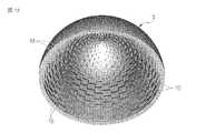
なお、第1および第2の実施形態において、プリズム10は、同心円状に回転させた形状を基本形状としているが、この場合、プリズムの配列ピッチが粗いと、プリズム10の縞々が見えやすくなる。このような見映えを改善するため、図15および図16に示す第5変形例のように、各プリズム10は中心軸C回りの円周方向(ドーム頂点を北極とした場合の経度方向)に複数に分割して千鳥配列にしてもよい。この場合でも、配光分布は変わらず、見た目の縞々感を緩和することができる。   In the first and second embodiments, the prism 10 has a basic shape that is concentrically rotated, but in this case, if the arrangement pitch of the prism is rough, the stripes of the prism 10 are easily visible. In order to improve such appearance, each prism 10 is arranged in the circumferential direction around the central axis C (longitude direction when the dome apex is the north pole) as in the fifth modification shown in FIGS. 15 and 16. It may be divided into a plurality of staggered arrays. Even in this case, the distribution of light distribution does not change, and it is possible to alleviate the appearance of stripes.

また、ドーム状の光学部品の表面にシボ処理を施し、見た目の雰囲気を変えるなどしてもよい。LED光源は、チップオンボード(COB)のような集約された1つの光源に限るものではなく、複数のLEDを配列した形態でもよく、複数のLEDを特定の配列にして見た目の効果を付けてもよい。   In addition, the surface of the dome-shaped optical component may be subjected to a graining process to change the appearance atmosphere. The LED light source is not limited to a single integrated light source such as a chip-on-board (COB), and may have a form in which a plurality of LEDs are arranged. Also good.

本発明は上記実施形態そのままに限定されるものではなく、実施段階ではその要旨を逸脱しない範囲で構成要素を変形して具体化できる。また、上記実施形態に開示されている複数の構成要素の適宜な組み合わせにより、種々の発明を形成できる。例えば、実施形態に示される全構成要素から幾つかの構成要素を削除してもよい。さらに、異なる実施形態にわたる構成要素を適宜組み合わせてもよい。
上述した実施形態はLED電球として説明したが、この発明に係る照明装置は、指向性のある光源とこの光源を囲う透光カバーとの組み合わせであれば、街路灯照明等についても適用することができる。
The present invention is not limited to the above-described embodiments as they are, and can be embodied by modifying the constituent elements without departing from the scope of the invention in the implementation stage. In addition, various inventions can be formed by appropriately combining a plurality of components disclosed in the embodiment. For example, some components may be deleted from all the components shown in the embodiment. Furthermore, constituent elements over different embodiments may be appropriately combined.
Although the above-described embodiment has been described as an LED bulb, the lighting device according to the present invention can be applied to street lamp lighting as long as it is a combination of a directional light source and a translucent cover surrounding the light source. it can.

1…LED電球、2…基材、2a…基材頂面、4…光源、5…光学部品、
5a…下端開口、6…透光カバー、6a…下端開口、10…プリズム、
11…駆動回路、S…虚像
DESCRIPTION OF SYMBOLS 1 ... LED bulb, 2 ... Base material, 2a ... Base material top surface, 4 ... Light source, 5 ... Optical component,
5a ... lower end opening, 6 ... translucent cover, 6a ... lower end opening, 10 ... prism,
11 ... Drive circuit, S ... Virtual image

Claims (8)

頂面を有する基材と、
前記基材頂面に配置された光源と、
下端開口を有するドーム状に形成され、前記基材頂面に前記下端開口側が固定され前記光源を覆った光学部品と、
前記基材頂面に固定され前記光源および光学部品を覆った透明性を有する透光カバーと、を備え、
前記光学部品は、壁部の肉厚が前記下端開口の径よりも小さく形成され、
前記光学部品は、前記光源からの光が入射するドーム内面あるいは光を外部に放出するドーム外面の全域に設けられた複数のプリズムを有し、前記プリズムは、前記光学部品のドーム頂点を北極としたときに入射した光線の緯度方向角度を前記光学部品の南半球方向に変えて出射し、前記光学部品を通して見た際に、前記光源の虚像を前記基材頂面から浮き上がった位置に形成することを特徴とする電球形の照明装置。
A substrate having a top surface;
A light source disposed on the top surface of the substrate;
An optical component formed in a dome shape having a lower end opening, the lower end opening side being fixed to the base material top surface and covering the light source;
A transparent cover that is fixed to the top surface of the base material and covers the light source and the optical component and has transparency,
The optical component is formed such that the wall thickness is smaller than the diameter of the lower end opening,
The optical component has a plurality of prisms provided on the entire inner surface of the dome on which light from the light source enters or the outer surface of the dome that emits light to the outside, and the prism has the dome apex of the optical component as a north pole. When the incident light beam is emitted in the direction of the southern hemisphere of the optical component, the virtual image of the light source is lifted from the top surface of the substrate when viewed through the optical component. A light bulb shaped lighting device characterized by
前記光学部品の側面方向に最も強い光度で光を出射する配光分布を有することを特徴とする請求項1に記載の電球形の照明装置。   2. The light bulb-shaped illumination device according to claim 1, wherein the light-emitting illumination device has a light distribution that emits light with the strongest luminous intensity in a lateral direction of the optical component. 前記光学部品は、透明な材料で形成されていること特徴とする請求項1又は2に記載の電球形の照明装置。   The light bulb-shaped illumination device according to claim 1 or 2, wherein the optical component is formed of a transparent material. 前記光学部品は、表面にシボが形成されていることを特徴とする請求項3に記載の電球形の照明装置。   4. The light bulb-shaped illumination device according to claim 3, wherein the optical component has a surface with a texture. 前記光学部品は、乳白材料で形成されていることを特徴とする請求項1又は2に記載の電球形の照明装置。   The light bulb-shaped lighting device according to claim 1, wherein the optical component is made of a milk white material. 前記光学部品は、壁部の肉厚が2mmで、透過率が90〜70%であることを特徴とする請求項5に記載の電球形の照明装置。   The light bulb-shaped lighting device according to claim 5, wherein the optical component has a wall thickness of 2 mm and a transmittance of 90 to 70%. 前記光学部品は、中心軸に沿った高さが前記下端開口の径よりも大きい縦長に形成されていることを特徴とする請求項1ないし6のいずれか1項に記載の電球形の照明装置。   The light bulb-shaped illumination device according to any one of claims 1 to 6, wherein the optical component is formed in a vertically long shape having a height along a central axis larger than a diameter of the lower end opening. . 前記各プリズムは、前記光学部品の経度方向に対して千鳥状に配置されていることを特徴とする請求項1に記載の電球形の照明装置。   The bulb-shaped illumination device according to claim 1, wherein the prisms are arranged in a staggered manner with respect to the longitude direction of the optical component.
JP2012254092A 2012-11-20 2012-11-20 Lighting device Pending JP2014102973A (en)

Priority Applications (1)

Application Number Priority Date Filing Date Title
JP2012254092A JP2014102973A (en) 2012-11-20 2012-11-20 Lighting device

Applications Claiming Priority (1)

Application Number Priority Date Filing Date Title
JP2012254092A JP2014102973A (en) 2012-11-20 2012-11-20 Lighting device

Publications (1)

Publication Number Publication Date
JP2014102973A true JP2014102973A (en) 2014-06-05

Family

ID=51025322

Family Applications (1)

Application Number Title Priority Date Filing Date
JP2012254092A Pending JP2014102973A (en) 2012-11-20 2012-11-20 Lighting device

Country Status (1)

Country Link
JP (1) JP2014102973A (en)

Cited By (4)

* Cited by examiner, † Cited by third party
Publication number Priority date Publication date Assignee Title
CN106662295A (en) * 2014-07-21 2017-05-10 飞利浦照明控股有限公司 Lighting device with virtual light source
US10928011B2 (en) 2016-07-14 2021-02-23 Signify Holding B.V. Solid-state lighting lamp
US10995933B2 (en) 2019-06-27 2021-05-04 Nichia Corporation Optical device and illumination device
US11204151B2 (en) 2019-12-27 2021-12-21 Nichia Corporation Optical device and illumination device

Cited By (6)

* Cited by examiner, † Cited by third party
Publication number Priority date Publication date Assignee Title
CN106662295A (en) * 2014-07-21 2017-05-10 飞利浦照明控股有限公司 Lighting device with virtual light source
US10533711B2 (en) 2014-07-21 2020-01-14 Signify Holding B.V. Lighting device with virtual light source
CN106662295B (en) * 2014-07-21 2020-07-14 昕诺飞控股有限公司 Lighting device with virtual light source
US10928011B2 (en) 2016-07-14 2021-02-23 Signify Holding B.V. Solid-state lighting lamp
US10995933B2 (en) 2019-06-27 2021-05-04 Nichia Corporation Optical device and illumination device
US11204151B2 (en) 2019-12-27 2021-12-21 Nichia Corporation Optical device and illumination device

Similar Documents

Publication Publication Date Title
TWI512237B (en) Lighting system
JP5363864B2 (en) Light emitting device and light bulb type LED lamp
TWI452232B (en) Lens and lighting device
WO2013190979A1 (en) Lighting device
JP2009026584A (en) Luminaire
KR101490065B1 (en) Lighting apparatus
JP5125562B2 (en) Lighting device
JP2013016463A (en) Optical device and light-emitting device having the same
JP2014500606A (en) LED bulb with light scattering optical structure
JP2011134508A (en) Lighting fixture
JP2012123907A (en) Lamp
JP6347390B2 (en) Lighting device
JP5547697B2 (en) Light emitting device and lighting device
JP2012182117A (en) Tubular lighting fixture, casing for tubular lighting fixture and both-side inner illumination-type signboard
JP2014102973A (en) Lighting device
JP2009009870A (en) Light source unit and compact self-ballasted lamp
JP2012048950A (en) Lamp with base and lighting fixture
JP2014135233A (en) Lighting apparatus
JP2014102995A (en) Lighting device
JP2022526654A (en) Luminescent device
WO2012035841A1 (en) Led illumination device
KR20080049347A (en) Lighting utilizing a white light-emitting diode
JP6067246B2 (en) Lighting device
JP2014182995A (en) Lighting system
JP5512447B2 (en) lighting equipment