JP2014182995A - Lighting system - Google Patents
Lighting system Download PDFInfo
- Publication number
- JP2014182995A JP2014182995A JP2013058169A JP2013058169A JP2014182995A JP 2014182995 A JP2014182995 A JP 2014182995A JP 2013058169 A JP2013058169 A JP 2013058169A JP 2013058169 A JP2013058169 A JP 2013058169A JP 2014182995 A JP2014182995 A JP 2014182995A
- Authority
- JP
- Japan
- Prior art keywords
- optical component
- light
- light source
- dome
- end opening
- Prior art date
- Legal status (The legal status is an assumption and is not a legal conclusion. Google has not performed a legal analysis and makes no representation as to the accuracy of the status listed.)
- Pending
Links
Images


Abstract
Description
この発明の実施形態は、発光ダイオード(LED)のように実装された面の法線方向に狭い配光分布を持つ光源を用いる照明装置に関する。 Embodiments of the present invention relate to an illumination device using a light source having a narrow light distribution in the normal direction of a surface mounted like a light emitting diode (LED).
照明装置としては、白熱電球や蛍光灯が広く用いられてきたが、寿命、発光効率、水銀汚染、紫外線漏れなどの問題を抱えていた。近年、これらの問題を解消する技術として、LED光源やEL(エレクトロルミネッセンス)光源が開発され、特にLED光源は一般の照明装置への利用が加速度的に広がっている。 Incandescent light bulbs and fluorescent lamps have been widely used as lighting devices, but have problems such as lifetime, luminous efficiency, mercury contamination, and ultraviolet light leakage. In recent years, as a technique for solving these problems, LED light sources and EL (electroluminescence) light sources have been developed, and in particular, the use of LED light sources for general lighting devices is accelerating.
しかしながら、LED光源は実装基板の法線方向に強く光を放出し、実装基板の法線方向となす角度をθとするとき、cosθに比例して光度が減衰する指向性を有している。これは、一般的なLED光源の構造が、1次光線を放出するLEDチップを、1次光線から2次光線に変換する蛍光体を含んだ保護層で面状に覆った構成としているためである。そのため、電球形照明装置では、実装基板の法線方向の光が強く、実装基板の側方から背面方向にかけては光がほとんど出ない光度分布となる。従って、正面から背面までほぼ均一な光度分布をもつ従来の白熱電球と、LED光源を用いた電球形照明装置とを置き換えた場合、天井や壁の明るさが著しく変わってしまい、違った照度空間となってしまう。 However, the LED light source emits light strongly in the normal direction of the mounting substrate, and has a directivity in which the light intensity attenuates in proportion to cos θ, where θ is an angle with the normal direction of the mounting substrate. This is because the structure of a general LED light source is such that the LED chip that emits primary light is covered in a planar shape with a protective layer containing a phosphor that converts primary light to secondary light. is there. Therefore, in the light bulb-type lighting device, the light intensity distribution is such that the light in the normal direction of the mounting substrate is strong, and the light is hardly emitted from the side of the mounting substrate toward the back surface. Therefore, when a conventional incandescent light bulb with a nearly uniform light intensity distribution from the front to the back is replaced with a light bulb-type lighting device using an LED light source, the brightness of the ceiling and walls changes significantly, resulting in a different illuminance space. End up.
LED光源を用いた電球形照明装置で背面方向まで光を放出する技術としては、LEDを実装する平面を多面体にして側面や背面方向を向いて配置する立体実装技術がある。また、別の技術として、LED光源の光により励起する蛍光体を透光カバーの内面に塗布し、透光カバー自体が光るようにした照明装置がある。 As a technique for emitting light in the back direction with a light bulb-type lighting device using an LED light source, there is a three-dimensional mounting technique in which a plane on which an LED is mounted is a polyhedron and is arranged facing the side or the back direction. As another technique, there is an illumination device in which a phosphor that is excited by light from an LED light source is applied to the inner surface of a translucent cover so that the translucent cover itself shines.
この発明が解決しようとする課題は、発光ダイオード(LED)のような光源を用いた場合でも、側面方向あるいは背面方向まで光を照射することのできる照明装置を提供することにある。 The problem to be solved by the present invention is to provide an illuminating device capable of irradiating light in a side surface direction or a back surface direction even when a light source such as a light emitting diode (LED) is used.
実施形態によれば、照明装置は、頂面を有する基材と、基材頂面に配置された光源と、下端開口を有するドーム状の断面形状に形成され、基材頂面に下端開口側が固定され光源を覆った光学部品と、基材頂面に固定され光源および光学部品を覆う透光カバーと、を備えている。光学部品は、壁部の肉厚が前記下端開口の径よりも小さく形成されている。光学部品は、光源からの光が入射するドーム内面あるいは光を外部に放出するドーム外面の少なくとも一方に設けられた複数のプリズムを有し、プリズムは、光学部品のドーム頂点を北極としたときに入射した光線の緯度方向角度を前記光学部品の南半球方向に変えて出射し、透光カバーは光学部品よりも低い透過率を有している。 According to the embodiment, the lighting device is formed in a dome-like cross-sectional shape having a base material having a top surface, a light source disposed on the base material top surface, and a lower end opening, and the lower end opening side is formed on the top surface of the base material. An optical component that is fixed and covers the light source, and a translucent cover that is fixed to the top surface of the substrate and covers the light source and the optical component. The optical component is formed so that the wall thickness is smaller than the diameter of the lower end opening. The optical component has a plurality of prisms provided on at least one of the inner surface of the dome on which light from the light source enters or the outer surface of the dome that emits light to the outside. The incident light beam is emitted with the latitude angle changed to the southern hemisphere direction of the optical component, and the translucent cover has a lower transmittance than the optical component.
以下、図面を参照しながら、種々の実施形態に係る照明装置について詳細に説明する。
(第1の実施形態)
図1は、第1の実施形態に係る電球形の照明装置としてLED電球1を示す断面図である。LED電球1は、中心軸Cに対して回転対称の形状をしている。
Hereinafter, illumination devices according to various embodiments will be described in detail with reference to the drawings.
(First embodiment)
FIG. 1 is a cross-sectional view showing an LED bulb 1 as a bulb-type lighting device according to the first embodiment. The LED bulb 1 has a rotationally symmetric shape with respect to the central axis C.
LED電球1は、前面に平坦な基材頂面2aを有する基材2と、基材頂面2aに実装されたLEDから成る光源4と、基材頂面2a上に配置されて光源4を覆うドーム状の光学部品5と、同じく基材頂面2aに配置されて光源4および光学部品5を覆う透光カバー6と、を備えている。
The LED bulb 1 includes a
基材2は、金属製の筐体かつ放熱部材であり、ほぼ切頭円錐状に形成されて上端(前面)に平坦なほぼ円形の基材頂面2aを有し、基材2の下端に口金8が設けられている。光源4は、基材頂面2aの中心に配置されている。基材2の内部には、光源4を駆動する駆動回路11が収納されている。口金8から給電された電力は、駆動回路11により光源4に供給され、光源4を発光させる構成となっている。基材2は、透光カバー6および口金8を保持してLED電球1の外面形状を形成するとともに、光源4の熱に対するヒートシンクと放熱板を兼ねている。
The
透光カバー6は、円形の下端開口6aを有する球状に形成されている。透光カバー6は、その下端開口6a側が基材頂面2aの周縁部に固定され、光源4および光学部品5を覆っている。透光カバー6は、例えば、透過率74%の乳白材料で形成され、外部に放出される光線を適度に拡散させるとともに、内部の光学部品5や光源4が透光カバーの外側から見えないようにしている。
The
光学部品5は、円形の下端開口5aと、中心軸C上に位置するドーム頂点Tと、を有する薄肉のドーム形状に形成されている。すなわち、光学部品5は、中心軸Cに沿った高さが下端開口5aの径よりも大きい、縦長に形成されている。そして、光学部品5は、下端開口5a側の下端を光源4の周囲で基材頂面2aに固定することにより、中心軸Cと同軸的に配置され、更に、光源4を覆っている。
The
光学部品5は、例えば、透過率が90%以上の透明樹脂により形成され、ドーム内面である入射面5bで光源4からの光を入射し、ドーム外面である出射面5cから外部へ光を放出する。光学部品5は、その入射面(ドーム内面)5b、あるいは、出射面(ドーム外面)5cの少なくとも一方に形成された複数のプリズムを一体に有している。本実施形態では、光学部品5の出射面5cの全域に複数のプリズム10が形成されている。各プリズム10は、例えば三角形(クサビ状)の断面を有し、中心軸Cと同軸の環状に形成されている。そして、複数のプリズム10は、ドーム頂点Tから下端開口5aに亘って並んで形成されている。
The
プリズム10は、光源4から入射した光を屈折あるいは反射して、光学部品5のドーム頂点Tを北極としたときに入射光線(破線矢印)を経度方向には作用させず緯度方向のみ南半球方向に曲げて外部に出射(実線矢印)させる。これにより、光学部品5は、光源4から出た光を、光源の側面方向および背面方向に向かって放出する。
The
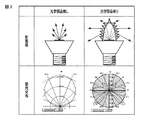
図2は、透光カバー6を外した状態でドーム状の光学部品5の有無による光度分布の違いを示す図である。光学部品5が無い場合は、法線(正面)方向に強い光の指光性を有しているが、ドーム状光学部品5を設置した場合、側面方向および背面方向へと光の指光性を変えることができる。ただし、光学部品5の作用は、なだらかに制御することは難しく、図示したように、局所的に光度の強弱の激しい光度分布となる。
FIG. 2 is a diagram showing a difference in luminous intensity distribution depending on the presence or absence of the dome-shaped
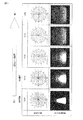
図3は、透光カバー6の乳白度合いを変えた場合の光度分布と、照明装置1を側面方向から見た透光カバー6の光り方を示している。図3において、上段の数値は、透光カバー6の透過率を表し、例えばT74%は透過率74%の透光カバー6であることを示している。一番左は、透明樹脂材料を用いた透光カバー6で、右に行くほど乳白の濃い水準としている。
FIG. 3 shows the luminous intensity distribution when the milky degree of the
透光カバー6が透明樹脂で形成されている場合、透光カバー6による拡散が無いため、図2で示したような局所的に光度の強弱の激しい光度分布となり、見た目にも透光カバー6の内部の光学部品5が発光しているのが直視される。これに対して、本実施形態では、透光カバー6を乳白材料で形成することで、すなわち、透光カバー6の透過率を光学部品5の透過率よりも低くすることにより、光度分布がなだらかになるとともに、透光カバー6内部が直視されるのを防止し透光カバー6全体が発光するように変えることができる。
When the
図4は、図3と同様に、透光カバー6の透過率の違いによる効率と、照明装置1の配光角(2θ・1/2)を示す。ここでの配光角(2θ・1/2)とは、光源4の法線方向(照明装置1の中心軸C方向)を0度として、0度光度の半値になる角度を2倍した値である。透明樹脂材料で形成した透光カバー6(透過率90%)の場合、実力的には光が十分に背面側に照射されているのだが、局所的な光度の強弱のため、定義に基づく配光角が非常に狭くなっている。これに対して、乳白樹脂材料で形成した透光カバー6では、透光カバー6での光の拡散性により、光学部品5による局所的な光度の強弱が敏感に緩和され、配光分布がなだらかになり配光角は安定して広配光となる。
FIG. 4 shows the efficiency due to the difference in transmittance of the light-transmitting
一方、効率については、透光カバー6の透過率が下がるほど劣化し、特に透過率が50%を下回ると急激に劣化する。このため、透光カバー6の透過率は50〜88%が最適値となる。
On the other hand, the efficiency deteriorates as the transmissivity of the
図1に示すように、ドーム状の光学部品5は、内面が中空にえぐられているため最大でも5mm以内の薄肉に設計されている。そのため、ドーム状の光学部品5は、中実円筒状の既存の光学部品と比べて射出成型プロセスなどの熱成形プロセスで冷え易く、かつ軽量であるため、量産性が非常に高くなっている。
As shown in FIG. 1, the dome-shaped
また、ドーム状の光学部品5は、従来のレンズ部品や導光部品と比べて広い下端開口5aを有し、光源4の光を入射する入射面5bが光源4から充分に離れている。そのため、入射面5bで反射した光が光源4に再吸収される確率が小さく、効率損失が少ない。更に、光源4からプリズム10が離れているため、光源4の仕様に非常に鈍感であり、COB(チップオンモード)光源や各種配列のSMD(表面実装型)光源に対しても同じ仕様のドーム状の光学部品5で対応することができる。そのため、LED光源の仕様を切り換えた場合でも、光学部品5をそのまま使用することができる。これにより、幅広い製品でドーム状の光学部品5を共有することができる。
Further, the dome-shaped
以上のように構成された第1の実施形態によれば、LED光源などを用いても、側面および背面方向にも光が届く、白熱電球のような光度分布を実現した電球形の照明装置を得ることができる。 According to the first embodiment configured as described above, there is provided a light bulb-shaped illumination device that achieves a light intensity distribution like an incandescent light bulb that can receive light in the side and back directions even when using an LED light source or the like. Can be obtained.
なお、第1の実施形態では、透光カバー6のドーム状外面にプリズム10を設けたが、これに限らず、ドーム状内面に複数のプリズムを設けてもよく、あるいは、内面および外面の両面にプリズムを設けても良い。
In the first embodiment, the
次に、種々の変形例に係る照明装置について説明する。なお、以下に述べる種々の変形例において、第1の実施形態と同一の部分には、同一の参照符号を付してその詳細な説明を省略し、異なる部分を中心に詳細に説明する。 Next, lighting devices according to various modifications will be described. Note that, in the various modifications described below, the same parts as those in the first embodiment are denoted by the same reference numerals, detailed description thereof is omitted, and detailed description will be made focusing on different parts.
(第1変形例)
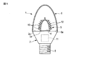
図5は、第1変形例に係る電球形の照明装置としてLED電球1を示す断面図である。第1の変形例において、LED電球1の基本的な構成は、第1の実施形態と同じであるが、透光カバー6は、球状ではなく、断面が縦長楕円形のドーム状に形成されている。すなわち、透光カバー6は内部の光学部品5を覆う形状であれば、その形状は限定されない。
(First modification)
FIG. 5 is a cross-sectional view showing an LED bulb 1 as a bulb-type illumination device according to a first modification. In the first modification, the basic configuration of the LED bulb 1 is the same as that of the first embodiment, but the
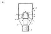
(第2変形例)
図6は、第2変形例に係る電球形の照明装置としてLED電球1を示す断面図である。第2の変形例において、LED電球1の基本的な構成は、第1の実施形態と同じであるが、透光カバー6は、有底の円筒形状に形成されている。透光カバー6は内部の光学部品5を覆う形状であれば、その形状は限定されない。
(Second modification)
FIG. 6 is a cross-sectional view showing an LED bulb 1 as a bulb-type illumination device according to a second modification. In the second modification, the basic configuration of the LED bulb 1 is the same as that of the first embodiment, but the
次に、他の実施形態に係る照明装置について説明する。なお、以下に述べる他の実施形態において、第1の実施形態と同一の部分には、同一の参照符号を付してその詳細な説明を省略し、異なる部分を中心に詳細に説明する。 Next, a lighting device according to another embodiment will be described. In other embodiments described below, the same parts as those in the first embodiment are denoted by the same reference numerals, detailed description thereof will be omitted, and different parts will be described in detail.
(第2の実施形態)
図7は、第2の実施形態に係る電球形の照明装置としてLED電球1を示す断面図である。第2の実施形態において、LED電球1の基本的な構成は第1の実施形態と同じであるが、ドーム状の光学部品5は、縦長のドーム状ではなく、横長のドーム状としている。すなわち、光学部品5は、下端開口5aの径Dよりも、中心軸Cに沿った高さHの方が小さく(D>H)なるように形成されている。光学部品5は、透明な材料で形成され、その入射面(ドーム状の内面)5bに複数のプリズム10が一体に設けられている。各プリズム10は、例えば三角形あるいはクサビ形状の断面を有し、中心軸Cと同軸の環状に形成されている。そして、複数のプリズム10は、ドーム頂点Tから下端開口6aに亘って、入射面上に並んで形成されている。
本実施形態のような高さが低くコンパクトな光学部品5を用いることにより、主として配光分布を側面方向を強化するようにしてもよい。
(Second Embodiment)
FIG. 7 is a cross-sectional view showing an LED bulb 1 as a bulb-type illumination device according to the second embodiment. In the second embodiment, the basic configuration of the LED bulb 1 is the same as that of the first embodiment, but the dome-shaped
By using the compact
(第3変形例)
図8は、第3変形例に係るLED電球1を示す断面図である。第3変形例において、光学部品5は、縦長のドーム状に形成されている。すなわち、光学部品5は、下端開口5aの径よりも、中心軸Cに沿った高さの方が大きくなるように形成されている。そして、光学部品5の入射面5bに複数のプリズム10が一体に設けられている。第3変形例において、LED電球1の他の構成は、第2の実施形態と同一である。
(Third Modification)
FIG. 8 is a cross-sectional view showing an LED bulb 1 according to a third modification. In the third modification, the
このように光学部品5の高さを下端開口5aの径よりも大きくすることで(H>D)、入射面5bを光源4から遠ざけて入射面5bで反射した光が光源4に再吸収されることを抑制するとともに、光源4の拡がりやLED仕様に対して鈍感に、すなわち光源4の詳細仕様に無頓着にさせることができ、様々な光源4仕様で共通に使用可能としている。
Thus, by making the height of the
第2の実施形態および第3変形例において、光学部品5は第1の実施形態と形状およびプリズム10の形成位置が異なるが、第1の実施形態と同様に、側面方向および背面方向にも光が届く、白熱電球のような光度分布を実現した電球形の照明装置を得ることができる。
In the second embodiment and the third modification, the
なお、第1および第2の実施形態において、LED光源は、チップオンボード(COB)のような集約された1つの光源に限るものではなく、複数のLEDを配列した形態でもよい。 In the first and second embodiments, the LED light source is not limited to a single integrated light source such as a chip on board (COB), but may be a form in which a plurality of LEDs are arranged.
(第3の実施形態)
図9は、第3の実施形態に係る蛍光灯形の照明装置1を示す斜視図である。第3の実施形態において、照明装置1の基本的な構成は第1の実施形態と同じである。
照明装置1は、LED光源4を線状に配置した細長い照明装置であり、図9(a)に示すように、例えば、1.2mほど直線状に引き伸ばした棒状の立体形状、あるいは、図2(b)に示すように、曲線状に引き伸ばした環状を有している。
(Third embodiment)
FIG. 9 is a perspective view showing a fluorescent lamp-type lighting device 1 according to the third embodiment. In 3rd Embodiment, the basic composition of the illuminating device 1 is the same as 1st Embodiment.
The illuminating device 1 is an elongated illuminating device in which the
照明装置1は、照明装置のほぼ全長に亘って延びる細長い直線状あるいは環状の基材2と、基材2の頂面2a上に並んで配置された複数のLED光源4と、を備えている。これらのLED光源4は、基材2の長手方向に沿って、所定の間隔を置いて並んでいる。基材2上に、断面がドーム状の光学部材5が取付けられ、光源4を覆っている。更に、基材2上に透光カバー6が取付けられ、光学部材5を覆っている。光学部材5および透光カバー6は、基材2の全長に亘って延びる、直線状あるいは環状に形成されている。
The lighting device 1 includes an elongated linear or
光学部品5は、例えば、透明樹脂により形成され、その入射面(ドーム内面)5b、あるいは、出射面(ドーム外面)5cの少なくとも一方に形成された複数のプリズム10を一体に有している。光学部品5は、光源4から出た光を、光源の側面方向および背面方向に向かって放出する。
The
透光カバー6は、断面形状が下端開口を有する球状に形成されている。透光カバー6は、その下端開口側が基材の頂面2aの周縁部に固定され、光源4および光学部品5を覆っている。透光カバー6は、例えば、透過率74%の乳白材料で形成され、外部に放出される光線を適度に拡散させるとともに、内部の光学部品5や光源4が透光カバーの外側から見えないようにしている。
直線状の基材2および透光カバー6の両端あるいは環状の基材および透光カバー6の両端間には、カバー23が装着され、例えば、このカバー23内に光源4を駆動する図示しない点灯回路等が設けられている。
上記のように構成された蛍光灯形の照明装置1においても、前述した第1の実施形態と同様の作用効果を得ることができる。
The
Covers 23 are mounted between both ends of the
Also in the fluorescent lamp type illumination device 1 configured as described above, it is possible to obtain the same effects as those of the first embodiment described above.
本発明は上記実施形態そのままに限定されるものではなく、実施段階ではその要旨を逸脱しない範囲で構成要素を変形して具体化できる。また、上記実施形態に開示されている複数の構成要素の適宜な組み合わせにより、種々の発明を形成できる。例えば、実施形態に示される全構成要素から幾つかの構成要素を削除してもよい。さらに、異なる実施形態にわたる構成要素を適宜組み合わせてもよい。
上述した実施形態はLED電球あるいは蛍光体形の照明装置として説明したが、この発明に係る照明装置は、指向性のある光源とこの光源を囲う光学部材と透光カバーとの組み合わせであれば、街路灯照明等についても適用することができる。
The present invention is not limited to the above-described embodiments as they are, and can be embodied by modifying the constituent elements without departing from the scope of the invention in the implementation stage. In addition, various inventions can be formed by appropriately combining a plurality of components disclosed in the embodiment. For example, some components may be deleted from all the components shown in the embodiment. Furthermore, constituent elements over different embodiments may be appropriately combined.
Although the above-described embodiment has been described as an LED bulb or a phosphor-type lighting device, the lighting device according to the present invention is a combination of a directional light source, an optical member surrounding the light source, and a translucent cover. The present invention can also be applied to street lighting.
1…LED電球、2…基材、2a…基材頂面、4…光源、5…光学部品、
5a…下端開口、6…透光カバー、6a…下端開口、10…プリズム、
11…駆動回路
DESCRIPTION OF SYMBOLS 1 ... LED bulb, 2 ... Base material, 2a ... Base material top surface, 4 ... Light source, 5 ... Optical component,
5a ... lower end opening, 6 ... translucent cover, 6a ... lower end opening, 10 ... prism,
11 ... Drive circuit
Claims (8)
前記基材頂面に配置された光源と、
下端開口を有するドーム状の断面形状を有し、前記基材頂面に前記下端開口側が固定され前記光源を覆った光学部品と、
前記基材頂面に固定され前記光源および光学部品を覆う透光カバーと、を備え、
前記光学部品は、壁部の肉厚が前記下端開口の径よりも小さく形成され、
前記光学部品は、前記光源からの光が入射するドーム内面あるいは光を外部に放出するドーム外面の少なくとも一方に設けられた複数のプリズムを有し、前記プリズムは、前記光学部品のドーム頂点を北極としたときに入射した光線の緯度方向角度を前記光学部品の南半球方向に変えて出射し、前記透光カバーは前記光学部品よりも低い透過率を有する照明装置。 A substrate having a top surface;
A light source disposed on the top surface of the substrate;
An optical component having a dome-like cross-sectional shape having a lower end opening, the lower end opening side being fixed to the top surface of the base material and covering the light source;
A translucent cover fixed to the top surface of the base material and covering the light source and the optical component,
The optical component is formed such that the wall thickness is smaller than the diameter of the lower end opening,
The optical component has a plurality of prisms provided on at least one of the inner surface of the dome on which light from the light source is incident or the outer surface of the dome that emits light to the outside. The illumination device has a transmissivity that is lower than that of the optical component.
Priority Applications (1)
| Application Number | Priority Date | Filing Date | Title |
|---|---|---|---|
| JP2013058169A JP2014182995A (en) | 2013-03-21 | 2013-03-21 | Lighting system |
Applications Claiming Priority (1)
| Application Number | Priority Date | Filing Date | Title |
|---|---|---|---|
| JP2013058169A JP2014182995A (en) | 2013-03-21 | 2013-03-21 | Lighting system |
Publications (1)
| Publication Number | Publication Date |
|---|---|
| JP2014182995A true JP2014182995A (en) | 2014-09-29 |
Family
ID=51701491
Family Applications (1)
| Application Number | Title | Priority Date | Filing Date |
|---|---|---|---|
| JP2013058169A Pending JP2014182995A (en) | 2013-03-21 | 2013-03-21 | Lighting system |
Country Status (1)
| Country | Link |
|---|---|
| JP (1) | JP2014182995A (en) |
Cited By (3)
| Publication number | Priority date | Publication date | Assignee | Title |
|---|---|---|---|---|
| WO2016051523A1 (en) * | 2014-09-30 | 2016-04-07 | 株式会社 東芝 | Optical element and illumination device |
| US10047928B2 (en) | 2016-11-10 | 2018-08-14 | Dongguan City Minleon Electronics Co., Ltd. | LED highlight decorative bulb |
| US10900616B2 (en) | 2016-09-01 | 2021-01-26 | Signify Holding B.V. | Light emitting device |
-
2013
- 2013-03-21 JP JP2013058169A patent/JP2014182995A/en active Pending
Cited By (5)
| Publication number | Priority date | Publication date | Assignee | Title |
|---|---|---|---|---|
| WO2016051523A1 (en) * | 2014-09-30 | 2016-04-07 | 株式会社 東芝 | Optical element and illumination device |
| JPWO2016051523A1 (en) * | 2014-09-30 | 2017-04-27 | 株式会社東芝 | Optical element and illumination device |
| US10900616B2 (en) | 2016-09-01 | 2021-01-26 | Signify Holding B.V. | Light emitting device |
| US11448369B2 (en) | 2016-09-01 | 2022-09-20 | Signify Holding B.V. | Light emitting device |
| US10047928B2 (en) | 2016-11-10 | 2018-08-14 | Dongguan City Minleon Electronics Co., Ltd. | LED highlight decorative bulb |
Similar Documents
| Publication | Publication Date | Title |
|---|---|---|
| JP5618097B2 (en) | Optical device and light emitting device including the same | |
| US8641238B2 (en) | Light source module | |
| WO2013190979A1 (en) | Lighting device | |
| JP5125562B2 (en) | Lighting device | |
| JP2008159453A (en) | Light source device, and lamp having same | |
| KR101490065B1 (en) | Lighting apparatus | |
| KR20130091242A (en) | Led illumination device | |
| TWI537523B (en) | Optical lens and lighting element using the same | |
| JP2011134508A (en) | Lighting fixture | |
| JP5547697B2 (en) | Light emitting device and lighting device | |
| JP2009009870A (en) | Light source unit and compact self-ballasted lamp | |
| JP2009245910A (en) | Long-distance reaching led luminaire | |
| JP2009140778A (en) | Illumination device | |
| JP2014182995A (en) | Lighting system | |
| JP2015138761A (en) | Lighting device | |
| JP2014102973A (en) | Lighting device | |
| US20150211690A1 (en) | Light source device | |
| JP2014102995A (en) | Lighting device | |
| JP6067246B2 (en) | Lighting device | |
| JP2008021561A (en) | Illumination device | |
| JP2013061399A (en) | Optical element, and illumination device | |
| JP2014056694A (en) | Lighting apparatus | |
| US9476562B2 (en) | Vehicle lighting device | |
| JP2017199586A (en) | Lighting device | |
| JP2012204211A (en) | Lighting fixture |