JP2012062704A - Door - Google Patents
Door Download PDFInfo
- Publication number
- JP2012062704A JP2012062704A JP2010208652A JP2010208652A JP2012062704A JP 2012062704 A JP2012062704 A JP 2012062704A JP 2010208652 A JP2010208652 A JP 2010208652A JP 2010208652 A JP2010208652 A JP 2010208652A JP 2012062704 A JP2012062704 A JP 2012062704A
- Authority
- JP
- Japan
- Prior art keywords
- door
- end plate
- opening
- recess
- fitting recess
- Prior art date
- Legal status (The legal status is an assumption and is not a legal conclusion. Google has not performed a legal analysis and makes no representation as to the accuracy of the status listed.)
- Granted
Links
Images


Abstract
Description
本発明は、収納家具や壁の開口部に開閉可能に設けられる扉に関する。 The present invention relates to a door that can be opened and closed at an opening of a storage furniture or a wall.
収納家具や壁の開口部に設けられる扉には、その開閉手段として取手やノブのような部材が取り付けられることが多いが、このような開閉手段は外観上目立つものである。近年ではこの種の扉にもデザイン性が求められる中で、取手やノブのような目立つ開閉手段を設けると、扉のデザインとうまくマッチせずに違和感を与えてしまうことがある。 A member such as a handle or a knob is often attached to the door provided in the storage furniture or the opening of the wall as an opening / closing means, but such an opening / closing means is conspicuous in appearance. In recent years, this kind of door is also required to be designed, and if a conspicuous opening / closing means such as a handle or knob is provided, the door design may not match well and may give a sense of incongruity.
特許文献1では、鏡板10の左右側縁部を左右縦枠20,20の内周側に形成した溝(鏡板呑み込み部21)に嵌合させて枠内に鏡板を設けた扉において、扉の閉じ側となる縦枠の外周側の側端部表面に断面湾曲状の把持部26を突出形成し、この把持部26に手指を入れて扉を開閉する構成が提案されている。この構成によれば、把持部が縦枠の一部として一体に形成されるので、デザインの一体感・統一感を損なわずに済む利点がある。
In Patent Document 1, in the door in which the left and right side edge portions of the
しかしながら、特許文献1記載の扉における把持部は、扉の閉じ側となる縦枠の側縁端部表面に突出形成されて閉じ方向に開口して設けられることになるので、この把持部による空間に手指を入れて扉を閉じるときに、扉と開口枠や戸当たりとの間(片開きの場合)や扉同士の間(両開きの場合、特許文献1の図3,図4参照)に手指を挟んでしまう恐れがある。 However, the gripping portion in the door described in Patent Document 1 is provided so as to protrude from the side edge end surface of the vertical frame on the door closing side and open in the closing direction. When closing the door by putting a finger in the door, the finger is placed between the door and the opening frame or door stop (in the case of one-sided opening) or between the doors (in the case of two-sided opening, see FIGS. 3 and 4 of Patent Document 1). There is a risk of pinching.
また、この把持部による開閉操作用の空間は、鏡板の側縁端部を嵌合する溝の底部に近い位置に形成されることになる(特許文献1の特に図1参照)ので、把持部の根元部分の強度が低下し、把持部が縦枠の表面から突出して形成されていることとも相俟って、把持部が破損しやすいものとなる。 Further, the space for opening and closing operation by the gripping portion is formed at a position close to the bottom of the groove for fitting the side edge end portion of the end plate (see particularly FIG. 1 of Patent Document 1). The strength of the root portion of the grip portion decreases and the grip portion is formed so as to protrude from the surface of the vertical frame.
さらに、縦枠の側縁端部に、鏡板嵌合用の溝を内周側に向けて開口するように形成すると共に、断面湾曲形状を有する把持部を表面に突出形成しなければならず、加工手間がかかりコストが嵩む。 Furthermore, a groove for fitting the end plate should be formed at the side edge of the vertical frame so as to open toward the inner peripheral side, and a gripping portion having a curved cross-section must be formed on the surface. It takes time and costs.
また、把持部が表面側に突出するので、この部分が扉開閉手段として機能することが外観上すぐに分かってしまい、扉全体または枠をできるだけフラットな構成にしたい場合のデザイン要求や、突出部を極力配して人体や家具などとの衝突の際に怪我や損傷を防止することの要求に応えることができない。開閉操作を容易且つ安全に行うためには把持部によって十分な空間を確保する必要があるが、前述のように鏡板嵌合用の溝と位置的に干渉することから、把持部を表面側に大きく突出させて形成せざるを得ず、フラットな扉とは遠くかけ離れた印象のものになってしまう。 In addition, since the gripping part protrudes to the surface side, it is immediately apparent from the appearance that this part functions as a door opening / closing means, and the design requirements and the protruding part when the entire door or frame is desired to be as flat as possible It is not possible to meet the demand for preventing injury and damage in the event of a collision with a human body or furniture. In order to perform the opening and closing operation easily and safely, it is necessary to secure a sufficient space by the gripping portion. However, as described above, the gripping portion is greatly increased on the surface side because it interferes with the end plate fitting groove. It must be formed by projecting, and the impression is far away from a flat door.
したがって、本発明が解決しようとする課題は、開閉の際に手指を挟む危険が生ずることなく容易に操作可能であり、枠材の表面から突出する部材や部分を無くした構成の扉を提供することにある。 Therefore, the problem to be solved by the present invention is to provide a door that can be easily operated without the danger of pinching fingers during opening and closing, and that has no member or part protruding from the surface of the frame member. There is.
この課題を解決するため、請求項1に係る本発明は、鏡板と、この鏡板の対向するいずれかの二辺または四周に設けられる框材とからなり、框材の内側木口面に形成される嵌合凹部に鏡板の側端部が嵌合されることにより鏡板が一対の框材の間または四周框材の内部に設けられてなる扉において、少なくとも一の框材には、鏡板の側端部を嵌合する嵌合凹部が形成された内側木口面に、該框材の表面から手指を入れて扉開閉を行うための把持凹部が該框材の内側木口面から内部に入り込むように凹状に形成されることを特徴とする。 In order to solve this problem, the present invention according to claim 1 is composed of a head plate and a saddle member provided on any two sides or four sides of the end plate facing each other, and is formed on the inner end face of the saddle member. In the door in which the end plate is provided between the pair of saddle members or inside the four-sided saddle member by fitting the side end portion of the end plate to the fitting recess, at least one saddle member has the side end of the end plate. A concave concave portion is formed so that a gripping concave portion for opening and closing the door by inserting a finger from the surface of the saddle material enters the inside from the inner wooden face surface of the saddle material. It is formed in this.
請求項2に係る本発明は、請求項1記載の扉において、前記嵌合凹部は框材の内側木口面から裏面側に切り欠き形成されており、鏡板は、この切り欠き形成された嵌合凹部に嵌合された状態で、その裏面側に設けられる挟持部材を介して、扉裏面側より固定具によって框材に固定されることを特徴とする。 According to a second aspect of the present invention, in the door according to the first aspect, the fitting recess is notched from the inner end surface of the saddle to the back side, and the end plate is fitted with the notch. It is characterized by being fixed to the saddle member by a fixture from the back side of the door through a clamping member provided on the back side in a state of being fitted in the recess.
請求項1に係る本発明によれば、扉の少なくとも一の框材において、鏡板の側端部を嵌合する嵌合凹部が形成された内側木口面に、該框材の表面から手指を入れて扉開閉を行うための把持凹部が該框材の内側木口面から内部に入り込むように凹状に形成されるので、この把持凹部に手指を入れて扉の開閉操作を行うとき(特に扉を閉じるとき)に、扉と開口枠や戸当たりとの間(片開きの場合)や扉同士の間(両開きの場合)に手指を挟む危険が回避され、安全且つ容易に扉の開閉を行うことができる。 According to the first aspect of the present invention, a finger is inserted from the surface of the saddle material into the inner side of the door in which the fitting recess for fitting the side edge of the end plate is formed in at least one of the saddle material of the door. Since the gripping recess for opening and closing the door is formed in a concave shape so as to enter the inside from the inner side of the wood, when opening and closing the door with a finger inserted in this gripping recess (especially closing the door) The risk of pinching fingers between the door and the opening frame or door stop (in the case of half-opening) or between the doors (in the case of double-opening) is avoided, and the door can be opened and closed safely and easily. it can.
また、把持凹部は、鏡板の側端部を嵌合する嵌合凹部と同じく、框材の内側木口面に形成されるので、框材の向きを変えることなく同一箇所でこれら嵌合凹部および把持凹部を加工することができ、加工手間およびコストが低減できる。 Further, since the holding recess is formed on the inner side of the saddle like the fitting recess for fitting the side end of the end plate, the fitting recess and the grip are held at the same place without changing the direction of the saddle. A recessed part can be processed and processing effort and cost can be reduced.
請求項2に係る本発明によれば、上記効果に加えて、鏡板固定作業を容易にすると共に、鏡板の側端部とこれを嵌合する嵌合凹部とについて厚さ方向での寸法誤差を許容して製造容易とすることができる効果が得られる。 According to the second aspect of the present invention, in addition to the above effect, the end plate fixing work is facilitated, and the side end portion of the end plate and the fitting concave portion to which the end plate is fitted have a dimensional error in the thickness direction. The effect which can be permitted and manufactured easily is acquired.
まず、本発明の構成について概括的に説明する。本発明は、鏡板と、この鏡板の対向するいずれかの二辺または四周に設けられる框材とからなり、框材の内側木口面に形成される嵌合凹部に鏡板の側端部が嵌合されることにより鏡板が一対の框材の間または四周框材の内部に設けられてなる扉において、少なくとも一の框材には、鏡板の側端部を嵌合する嵌合凹部が形成された内側木口面に、該框材の表面と鏡板の表面との間の厚さ方向距離範囲内であって框材の表面の内側突出縁によって覆われる把持凹部が形成され、この把持凹部に手指を入れて扉開閉を行うことを特徴とする。 First, the configuration of the present invention will be described generally. The present invention comprises a head plate and a saddle member provided on any two sides or four sides of the end plate opposite to each other, and a side end portion of the end plate is fitted into a fitting recess formed on the inner end of the saddle member. Thus, in the door in which the end plate is provided between the pair of saddle members or inside the four-sided saddle member, at least one saddle member has a fitting recess for fitting the side end portion of the end plate. A gripping recess is formed on the inner side of the mouthpiece and is covered with an inner protruding edge of the surface of the saddle material within a distance in the thickness direction between the surface of the saddle member and the surface of the end plate. The door is opened and closed.
扉の寸法は、設置される開口部の寸法に合わせて適宜に決定されるが、一般的に、高さ400〜2100mm、幅350〜1600mm、厚さ25〜50mmである。 Although the dimension of a door is suitably determined according to the dimension of the opening part installed, it is generally 400-2100 mm in height, 350-1600 mm in width, and 25-50 mm in thickness.
框材は、一般に集成材から形成されるが、無垢材や、矩形状に組まれた芯材の表裏に木質パネルを貼着してなるフラッシュパネル構造体から形成されても良い。框材の表面には、化粧紙や化粧シートの貼着や塗装などによる化粧が施されても良い。化粧紙や化粧シートなどを貼着して化粧を施す場合には、シートの両端部を框材の内側木口面に形成される嵌合凹部に挿入することで、化粧の切れ目が露呈しない美麗な仕上げとすることができる。また、把持凹部は框材の内側木口面に形成されると共に表面に覆われているため目視されにくいので、塗装による化粧を行う場合には把持凹部の内部への塗装を省略しても良い。 The brazing material is generally formed of a laminated material, but may be formed of a solid material or a flash panel structure in which a wooden panel is bonded to the front and back of a rectangular core material. The surface of the glaze may be decorated with a decorative paper or a decorative sheet attached or painted. When applying makeup by attaching decorative paper or a decorative sheet, insert both ends of the sheet into the mating recesses formed on the inner side of the glazing, so that the makeup breaks are not exposed. It can be finished. In addition, since the gripping recess is formed on the inner side of the bran and is covered with the surface, it is difficult to visually check. Therefore, when applying makeup by painting, painting inside the gripping recess may be omitted.
鏡板は、集成材、無垢材、少なくとも表面に化粧が施された繊維板や合板、樹脂パネル、ガラス、木質基板の表面にミラーを設けたものなどを使用することができる。鏡板には任意に化粧を施すことができる。この場合の化粧は、前述した框材についての化粧と同様にして行うことができ、框材と同様または異なる化粧を行うことができる。 As the end plate, a laminated material, a solid material, a fiberboard or plywood having makeup applied at least on its surface, a resin panel, glass, or a substrate provided with a mirror on the surface of a wooden substrate can be used. The end plate can be arbitrarily decorated. The makeup in this case can be performed in the same manner as the makeup for the above-described glaze, and the makeup similar to or different from that of the glaze can be performed.
以下に実施例を挙げて本発明を詳述するが、本発明はこれら実施例に限定されるものではなく、特許請求の範囲の記載によって定義される発明の範囲内において様々な変形態様を取り得る。 Hereinafter, the present invention will be described in detail with reference to examples. However, the present invention is not limited to these examples, and various modifications can be made within the scope of the invention defined by the description of the scope of claims. obtain.
図1および図2には本発明の一実施形態による扉1が示されている。この扉1は、鏡板10の四周に框材20(21〜24)が設けられて構成されている。より詳しくは、上下框材21,22および左右框材23,24の各内側木口面には、鏡板10の対応する側端部11を嵌合する嵌合凹部25が長さ方向に亘って連続的に延長形成されている。図2(a),(b)には左右框材23,24の内側木口面に形成された嵌合凹部25(25a,25b)に鏡板10の側端部11(左右側端部11a,11b)がそれぞれ嵌合されている状態が示されている。図示されないが、同様に、上下框材21,22の内側木口面に形成された嵌合凹部に鏡板10の側端部(上下側端部)11がそれぞれ嵌合されている。この実施例では鏡板10の側端部11が下面側において薄く形成されて突出しており、この突出した側端部11が嵌合凹部25に嵌合されることによって鏡板10が框内に固定される。
1 and 2 show a door 1 according to an embodiment of the present invention. The door 1 is configured by providing brazing materials 20 (21 to 24) around the four ends of the
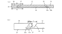
図2(a),(b)に明らかなように、左框材23の内側木口面には、その表面26(=扉1の表面)から手指を入れて扉開閉を行うための把持凹部27が左框材23の内側木口面から内部に入り込むように凹状に形成されている。この実施形態では、左框材23の内側木口面から断面湾曲状に後退する把持凹部27として示されており、扉表面26から鏡板10の表面12までの厚さ範囲に亘って形成され、嵌合凹部25に連続している。
As is apparent from FIGS. 2A and 2B, the gripping
上下框材21,22の左右側端部は、左右框材23,24の内側木口面に対応した形状を有する。すなわち、図2(b)に示されるように、上下框材21,22の左右側端部は、鏡板10の左右側端部11a,11bと同形状に突出形成された突出縁部28a,28bを有していて左右框材23,24の嵌合凹部25a,25bに嵌合可能であると共に、この突出縁部28a,28bの上方において、左側端部では左框材23の内側木口面に形成された把持凹部27と同形状の断面湾曲状凹部29が形成され、右側端部は右框材24の内側木口面30に面接する形状とされている。また、突出縁部28a,28bの下方においても、左右框材23,24の内側木口面に面接する形状を有している。そして、上下框材21,22の突出縁部28a,28bを左右框材23,24の嵌合凹部25a,25bに嵌合させると共に、その上下において左右框材23,24の内側木口面に沿って当接させた状態で框組みしたときに、左右框材23,24と上下框材21,22の表裏面がそれぞれ略面一となるように設計されている。図2(b)には左右框材23,24と下框材22との組み付け状態が示されているが、左右框材23,24と上框材21との組み付け状態も同様である。また、上記のように組み付けられる箇所において、各框材の内側木口面には対向する箇所にダボ穴(図示せず)が形成され、対向する一対のダボ穴にダボ(図示せず)を嵌合することによって框組みが行われる。
The left and right end portions of the upper and
この扉1の製造方法について説明する。上下左右の框材20(21〜24)の内側木口面となる箇所に長さ方向に亘って嵌合凹部25(25a,25b)を形成すると共に、左框材23についてはその内側木口面にさらに把持凹部27を形成する。さらに、各框材が組み付けられる箇所においてダボ穴を対向形成する。このようにして各框材の内側木口面に形成された嵌合凹部25およびダボ穴にそれぞれ接着剤を塗布し、嵌合凹部25に鏡板10の側端部11を嵌入すると共にダボ穴にダボを嵌入することによって、框材20(21〜24)による框組内に鏡板10が嵌合されて扉1が形成される。この際に嵌合凹部25やダボ穴に塗布した接着剤が框材の内側木口面にあふれ出すことがあっても、把持凹部27が湾曲状に後退して形成されているので、あふれ出した接着剤が扉1の表面に露呈することが無く、見栄えを損なわない。
The manufacturing method of this door 1 is demonstrated. A fitting recess 25 (25a, 25b) is formed in the longitudinal direction at a position that becomes the inner side face of the top, bottom, left and right side members 20 (21 to 24), and the
この実施例の扉1は、玄関収納などの収納家具の開口部において、右框材24に蝶番(図示せず)を取り付けて対向する側板に対して回転可能に設置される開き扉として使用されるものである。そして、左框材23の内側木口面に長さ方向(上下方向)に亘って形成された把持凹部27に手指を入れて開閉操作を行うことができるものである。把持凹部27は扉1の内方に向いて開口しているため、開閉操作の際に、扉同士の間や扉と側板との間に手指を挟む危険が回避され、安全且つ容易に扉の開閉を行うことができる。
The door 1 of this embodiment is used as an opening door that is installed rotatably on a facing side plate by attaching a hinge (not shown) to the
なお、この扉1を逆方向の開き扉、すなわち左框材24に蝶番を取り付けて対向する開口縦枠に対して回転可能に設置される開き扉として使用する場合は、把持凹部27を右框材23の内側木口面に形成すれば良い。また、左右框材23,24の内側木口面にそれぞれ把持凹部27を形成しておけば、両方向の開き扉に使用可能な扉1となる。また、この扉1を開き扉として使用する場合も、両方向への移動を可能にするために、左右框材23,24の内側木口面にそれぞれ把持凹部27を形成することが好ましい。
When the door 1 is used as an opening door in the reverse direction, that is, as an opening door that is installed on the
実施例1の把持凹部27は、図3(a)にも示すように、框表面(扉表面)から断面湾曲形状に後退する凹部形状を有するものとされているが、図3(b)に示すように、表面側の内方突出縁部31を残して断面矩形状の凹部形状を有するものとして形成しても良い。いずれの形状であっても、把持凹部27の厚さ方向寸法aは10〜25mm、奥行寸法bは3〜15mmとすることにより、手指を入れやすい空間を与えることができる。
As shown in FIG. 3A, the gripping
なお、図3(b)は左框材23の内側木口面に嵌合凹部25aおよび把持凹部27を形成する場合の実施例として示されているが、実施例1について既述したように、これに代えてまたはこれと共に、他の框材の内側木口面に把持凹部27を形成しても良く、その場合の把持凹部27の形状や鏡板の嵌合状態なども図3(b)と同様にすることができる。下記する図3(d)〜図3(f)についても同様である。
FIG. 3B shows an example in which the
また、図3(c)に示すように、実施例1と同様に框表面(扉表面)から断面湾曲形状に後退する凹部形状を有するものとしつつも、嵌合凹部25aには至らず、嵌合凹部25aとの間に突出縁部32を挟んで隣接するように形成しても良い。このようにすると、鏡板10の左側端部11aが表裏において同じ深さで嵌合凹部25aに嵌合されることになるので、より強固に鏡板10を框内に固定することができる利点がある。
Further, as shown in FIG. 3 (c), it has a concave shape that recedes from the saddle surface (door surface) to a curved cross-sectional shape as in the first embodiment, but does not reach the fitting
図3(d)に示す実施例は、嵌合凹部25aが左框材23の内側木口面から裏面側にかけて断面L字状に切り欠き形成されており、この切り欠き形成された嵌合凹部25aに鏡板10の左側端部11aを嵌合させた状態で、その裏面側に設けられる挟持部材33を介して、扉裏面側よりステープルなどの固定具34によって左框材23に固定される。断面L字状に切り欠き形成された嵌合凹部25aは、鏡板10の肉厚部分の厚さtと略同一厚であり、框表面(扉表面)と平行な水平面25cと、框材の木口面と平行な垂直面25dとを有する。さらに、この実施例では鏡板10の左側端部11aと挟持部材33との厚さ合計が鏡板10の肉厚部分の厚さtと略同一であるので、裏面から見たときに左框材23と挟持部材33と鏡板10とがほぼ隙間なく略面一に連続することになり、フラットな外観を与える。
In the embodiment shown in FIG. 3 (d), the
この実施例によると鏡板10の固定作業が容易である。すなわち、上記したように上下左右の框材20(21〜24)の内側木口面から裏面にかけて断面L字状に切り欠いて嵌合凹部25を形成すると共に、左框材23についてはその内側木口面にさらに把持凹部27を形成し、さらに、各框材が組み付けられる箇所においてダボ穴を対向形成する。そして、各框材の内側木口面に形成されたダボ穴に接着剤を塗布し、ダボ穴にダボを嵌入することによって、框材20(21〜24)による框組を形成する。このとき、框組みされた框材20の裏面には嵌合凹部25が露出した状態となっているので、その水平面25cおよび垂直面25dに接着剤を塗布した後、鏡板10を裏面側から嵌め込んで、その側端部11(11a)の表面を水平面25cに押し付けると共にその木口面を垂直面25dに当てがい、それらの当接面同士を接着剤で接着固定する。固定された鏡板10の側端部11aの裏面側に接着剤を塗布し、挟持部材33を該鏡板側端部裏面および嵌合凹部25aの垂直面25dに当接させて接着し、さらに裏面側からステープル34などの固着具を打ち付けて、鏡板10を介して左框材23に固定する。
According to this embodiment, the fixing operation of the
図3(a)〜図3(c)のように嵌合凹部25を鏡板側端部11が挿入される凹溝として形成する場合には、それらの厚さ寸法について厳密な精度が要求されるが、この実施例では、上述したように、框材の内側木口面から裏面にかけて切り欠かれた断面L字状の嵌合凹部25に鏡板側端部を嵌め込んで固定するので、その作業が容易であると共に、多少の寸法誤差による製造の不具合を回避することができる。 When the fitting concave portion 25 is formed as a concave groove into which the end plate side end portion 11 is inserted as shown in FIGS. 3 (a) to 3 (c), strict accuracy is required for the thickness dimension thereof. However, in this embodiment, as described above, the end portion on the side of the end plate is fitted into and fixed to the fitting recess 25 having an L-shaped cross-section cut out from the inner side of the wood to the back surface. In addition to being easy, manufacturing defects due to some dimensional errors can be avoided.
なお、図3(d)において把持凹部27の形状については実施例1と同様の形状(図3(a))が採用されているが、これに代えて図3(b),図3(c)に示されるような形状を採用しても良いことは言うまでもない。
In FIG. 3 (d), the shape of the gripping
図3(e)に示す実施例は図3(d)の変形例であり、左框材23の内側木口面から裏面にかけて切り欠かれた断面L字状の嵌合凹部25の寸法(裏面から水平面25cまでの距離)を鏡板側端部11aの厚さと略同一とした点で異なっている。この実施例では、扉裏面がフラットにはならないが、その他の点(鏡板固定作業が容易であること、多少の寸法誤差が許容されること)は同様である。また、この実施例によれば、把持凹部27の扉表面からの深さを大きく取ることができるので、この部分に手指をかけて開閉操作を行うことがより容易になる利点がある。
The embodiment shown in FIG. 3 (e) is a modification of FIG. 3 (d), in which the dimension (from the back surface) of the fitting recess 25 having an L-shaped cross-section cut out from the inner side of the
図3(f)に示す実施例は、左框材23の内側木口面において厚さ方向中央に鏡板10の側端部を嵌合する嵌合凹部25aを形成し、その表裏にそれぞれ断面湾曲状の把持凹部27,27を形成したものである。この実施例による扉は、表裏いずれからでも開閉操作可能である。この扉は、左框材23の内側木口面において嵌合凹部25aの表裏両側に把持凹部27,27を形成する点を除いて、実施例1の扉1と同様にして製造することができる。
In the embodiment shown in FIG. 3 (f), a
さらに別の実施例による扉2が図4および図5に示されている。この実施例の扉2は、框材20(21〜24)については実施例1の扉1の框材と同様に、それらの内側木口面に嵌合凹部25に形成されると共に左框材23の内側木口面にはさらに断面湾曲状の把持凹部27が形成されているが、鏡板の形状が異なっている。すなわち、この扉2における鏡板10は、その裏面側の四周縁を小さな厚さで突出させて、嵌合凹部25(25a)に嵌合する側端部11(11a)とし、その根元部分から傾斜面13を介して肉厚部14を有するように形成され、正面から見ると中央領域を占める肉厚部14が矩形状に隆起した形状に観察されるものである。
A
この実施例においても、左框材23の内側木口面に形成した把持凹部27と鏡板10の左側縁の傾斜面13との間に手指を差し込む空間が形成されるので、扉の開閉操作を安全且つ容易に行うことができる。この場合、把持凹部27の厚さ方向寸法aは10〜25mm、奥行寸法bは3〜15mm、把持凹部27の表面側端部と隆起肉厚部14の端部との間の距離cは15〜40mmとすることにより、手指を入れやすい空間を与えることができる。
Also in this embodiment, a space for inserting a finger is formed between the
1,2 扉
10 鏡板
11 側端部
11a 左側端部
11b 右側端部
12 鏡板の表面
13 傾斜面
14 肉厚部
20 框材
21 上框材
22 下框材
23 左框材
24 右框材
25 嵌合凹部
25a 左框材の内側木口面に形成した嵌合凹部
25b 右框材の内側木口面に形成した嵌合凹部
25c 水平面
25d 垂直面
26 框表面ないし扉表面
27 把持凹部
28a,28b 上下框材の突出縁部
29 上下框材の断面湾曲状凹部
30 右框材の内側木口面
31 左框材の把持凹部の表面側に形成される内方突出縁部
32 左框材の把持凹部と嵌合凹部との間に形成される突出縁部
33 挟持部材
34 固定具
1, 2
Claims (2)
Priority Applications (1)
| Application Number | Priority Date | Filing Date | Title |
|---|---|---|---|
| JP2010208652A JP5663248B2 (en) | 2010-09-16 | 2010-09-16 | door |
Applications Claiming Priority (1)
| Application Number | Priority Date | Filing Date | Title |
|---|---|---|---|
| JP2010208652A JP5663248B2 (en) | 2010-09-16 | 2010-09-16 | door |
Publications (2)
| Publication Number | Publication Date |
|---|---|
| JP2012062704A true JP2012062704A (en) | 2012-03-29 |
| JP5663248B2 JP5663248B2 (en) | 2015-02-04 |
Family
ID=46058682
Family Applications (1)
| Application Number | Title | Priority Date | Filing Date |
|---|---|---|---|
| JP2010208652A Active JP5663248B2 (en) | 2010-09-16 | 2010-09-16 | door |
Country Status (1)
| Country | Link |
|---|---|
| JP (1) | JP5663248B2 (en) |
Cited By (2)
| Publication number | Priority date | Publication date | Assignee | Title |
|---|---|---|---|---|
| JP2014070326A (en) * | 2012-09-27 | 2014-04-21 | Dainippon Printing Co Ltd | Door |
| KR200472823Y1 (en) * | 2013-11-08 | 2014-05-22 | 송재구 | door ornament structure |
Families Citing this family (1)
| Publication number | Priority date | Publication date | Assignee | Title |
|---|---|---|---|---|
| CN106639695B (en) * | 2016-11-28 | 2018-10-09 | 嘉兴市新飞腾塑业有限公司 | Adjustable door-inhale |
Citations (4)
| Publication number | Priority date | Publication date | Assignee | Title |
|---|---|---|---|---|
| JPS58101987U (en) * | 1981-12-29 | 1983-07-11 | 松下電工株式会社 | door with handle |
| JPS62115491U (en) * | 1986-01-13 | 1987-07-22 | ||
| JPS63165055U (en) * | 1987-04-18 | 1988-10-27 | ||
| JPH01157880U (en) * | 1988-04-23 | 1989-10-31 |
-
2010
- 2010-09-16 JP JP2010208652A patent/JP5663248B2/en active Active
Patent Citations (4)
| Publication number | Priority date | Publication date | Assignee | Title |
|---|---|---|---|---|
| JPS58101987U (en) * | 1981-12-29 | 1983-07-11 | 松下電工株式会社 | door with handle |
| JPS62115491U (en) * | 1986-01-13 | 1987-07-22 | ||
| JPS63165055U (en) * | 1987-04-18 | 1988-10-27 | ||
| JPH01157880U (en) * | 1988-04-23 | 1989-10-31 |
Cited By (2)
| Publication number | Priority date | Publication date | Assignee | Title |
|---|---|---|---|---|
| JP2014070326A (en) * | 2012-09-27 | 2014-04-21 | Dainippon Printing Co Ltd | Door |
| KR200472823Y1 (en) * | 2013-11-08 | 2014-05-22 | 송재구 | door ornament structure |
Also Published As
| Publication number | Publication date |
|---|---|
| JP5663248B2 (en) | 2015-02-04 |
Similar Documents
| Publication | Publication Date | Title |
|---|---|---|
| JP5663248B2 (en) | door | |
| JP6472215B2 (en) | Fire door | |
| JP2016169507A (en) | Window frame joint member, and window frame using the same | |
| JP7246183B2 (en) | Mounting structure of translucent member, structure of building door, and building door | |
| KR20170000172U (en) | Furniture's Door Assembly | |
| JP3213833U (en) | Flash panel with window member | |
| JP7186567B2 (en) | Fittings | |
| JP6379016B2 (en) | Door frame device, cap member thereof and construction method of door frame device | |
| KR200434569Y1 (en) | Material for finishing side of panel for furniture | |
| JP6775352B2 (en) | Shelf board | |
| JP2020094338A (en) | Decorative cap and fitting | |
| JP3845779B2 (en) | Panel edge mounting structure of toilet booth | |
| JP7353137B2 (en) | frame fittings | |
| JP3126105U (en) | Opening frame for wall opening | |
| JP2017210789A (en) | Fitting frame | |
| JP2018102468A (en) | Fixation structure of shelf board and construction method of shelf board | |
| JP4881675B2 (en) | Frame and frame mounting structure | |
| JP6854635B2 (en) | Parting frame and its construction method | |
| JP2017057555A (en) | Panel and door with decorative joint | |
| JP2022030022A (en) | Fitting | |
| TWM634861U (en) | Fastening structure for door frame | |
| JP2005336972A (en) | Opening frame | |
| JP2000213244A (en) | Glass fixture for glass door, and glass door | |
| JP5394883B2 (en) | Bowl-shaped panel | |
| JP2021017749A (en) | Parting material, opening structure therewith, and method of constructing the same |
Legal Events
| Date | Code | Title | Description |
|---|---|---|---|
| A621 | Written request for application examination |
Free format text: JAPANESE INTERMEDIATE CODE: A621 Effective date: 20130903 |
|
| A977 | Report on retrieval |
Free format text: JAPANESE INTERMEDIATE CODE: A971007 Effective date: 20140325 |
|
| A131 | Notification of reasons for refusal |
Free format text: JAPANESE INTERMEDIATE CODE: A131 Effective date: 20140422 |
|
| A521 | Written amendment |
Free format text: JAPANESE INTERMEDIATE CODE: A523 Effective date: 20140613 |
|
| TRDD | Decision of grant or rejection written | ||
| A01 | Written decision to grant a patent or to grant a registration (utility model) |
Free format text: JAPANESE INTERMEDIATE CODE: A01 Effective date: 20141111 |
|
| A61 | First payment of annual fees (during grant procedure) |
Free format text: JAPANESE INTERMEDIATE CODE: A61 Effective date: 20141208 |
|
| R150 | Certificate of patent or registration of utility model |
Ref document number: 5663248 Country of ref document: JP Free format text: JAPANESE INTERMEDIATE CODE: R150 |