JP2012030181A - Mound-shaped drying furnace used for coating elevator design goods - Google Patents
Mound-shaped drying furnace used for coating elevator design goods Download PDFInfo
- Publication number
- JP2012030181A JP2012030181A JP2010172624A JP2010172624A JP2012030181A JP 2012030181 A JP2012030181 A JP 2012030181A JP 2010172624 A JP2010172624 A JP 2010172624A JP 2010172624 A JP2010172624 A JP 2010172624A JP 2012030181 A JP2012030181 A JP 2012030181A
- Authority
- JP
- Japan
- Prior art keywords
- drying furnace
- mountain
- hot air
- inclined portion
- horizontal portion
- Prior art date
- Legal status (The legal status is an assumption and is not a legal conclusion. Google has not performed a legal analysis and makes no representation as to the accuracy of the status listed.)
- Granted
Links
Images


Landscapes
- Coating Apparatus (AREA)
Abstract
Description
本発明の実施の形態は、エレベータ意匠品の塗装に用いる山型乾燥炉に関する。 Embodiments of the present invention relate to a mountain drying furnace used for painting an elevator design product.
従来、エレベータの乗りかごのドアや側板、乗り場ホールのドアや三方枠等(以下、意匠品と言う)には、顧客のニーズに合わせて様々な色彩の塗装が施されている。
このとき、これらの意匠品に塗装を施す塗装ラインにおいては、図9に示したように、前工程のプレス加工ライン(図示せず)から搬送されてきた意匠品1を、無端状に延びて塗装ラインを循環するコンベヤチェーン2の最初の部分2aに吊り下げる。
すると、吊り下げられた意匠品1は、コンベヤチェーン2の矢印方向への移動に伴い、前処理ブース3においてシャワー洗浄、酸洗、リン酸亜鉛被膜処理等の前処理が施された後、乾燥炉4の第1の部分4A内でUターンする間に加熱されて乾燥し、防錆能力が向上するとともに、次の塗装工程において吹き付けられる塗料の密着性が向上する。
次いで、乾燥炉4から出た意匠品1は、塗装ブース5A,5Bで下塗りおよび上塗りが施された後、乾燥炉4の第2の部分4B内でUターンする間に加熱されて乾燥し、硬い塗膜が形成される。
そして、塗装が完了した意匠品1は、コンベヤチェーン2の最終部分2bにおいて取り外され、梱包されて、エレベータを設置する工事現場へと発送される。
Conventionally, elevator car doors and side panels, landing hall doors, three-way frames, etc. (hereinafter referred to as “design products”) have been painted in various colors to meet customer needs.
At this time, in the coating line for coating these design products, as shown in FIG. 9, the
Then, the suspended
Next, the
Then, the finished
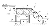
上述した塗装ラインにおいて意匠品を加熱し乾燥させる乾燥炉4は、図10に模式的に示したように、出入口を有する傾斜部分4aと、乾燥処理が施される水平部分4bとを有しており、この水平部分4bが出入口より上方に設けられていることから、一般に、山型乾燥炉と呼ばれている。
また、燃焼装置6で発生した熱気Aが配管7aを通って水平部分4bに供給され、水平部分4bの内部で移動する意匠品1を高温雰囲気に保持して加熱し乾燥させるようになっている。
そして、意匠品1の加熱、乾燥に用いられた熱気Aは、その大半が配管7bを通って燃焼装置6に戻るが、その一部は配管7cを通って取り出され、塗料から揮発した成分を除去する工程に送られる。
The
Further, the hot air A generated in the
And most of the hot air A used for heating and drying the
このとき、乾燥炉4の水平部分4bの床面4cは、傾斜部分4aに設けられている出入口の上端部分4dに対し、十分に大きい上下方向寸法H1だけ上方に設けられている。
これにより、水平部分4bの内部に滞留している熱気Aは、傾斜部分4aを下って出入口から炉外に漏出することがない。
At this time, the
Thereby, the hot air A staying inside the
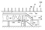
ところで、図11に示したように、塗装ラインを設ける建屋に天井梁9が設けられている場合は、乾燥炉4の水平部分4bの天井高さH2の値を大きく取ることができない。
すると、乾燥炉4の水平部分4bの床面4cが、傾斜部分4aの出入口の上端部分4dに対し、上下方向寸法H3だけ下方に位置することになる。
By the way, as shown in FIG. 11, when the
Then, the
特に、エレベータの意匠品には、幅方向の寸法は小さいが上下方向の寸法が大きいパネルが多いため、水平部分4bの床面4cの上下方向位置を低くせざるを得ず、上下方向寸法H3の値がより大きくなる傾向にある。
In particular, since there are many panels having a small size in the width direction but a large size in the vertical direction in the design of the elevator, the vertical position of the
これにより、図11中に矢印で示したように、水平部分4bの内部に滞留している熱気Aの一部が出入口から炉外に漏出して熱エネルギーが失われるため、燃焼装置6で消費される燃料が増加し、ランニングコストがかさむことになる。
そのため、乾燥炉4の出入口にエアカーテンを設けて熱気Aが炉外に出ないようにしているが、熱気Aの炉外への漏出を完全に防止することは困難である。
As a result, as indicated by the arrows in FIG. 11, a part of the hot air A staying inside the
Therefore, an air curtain is provided at the entrance / exit of the
そこで、本発明の実施の形態の目的は、乾燥炉の水平部分を傾斜部分に対して十分に上方に設けることができない場合であっても、水平部分の内部に滞留している熱気が傾斜部分を通って乾燥炉の出入口から炉外に漏出することがない、新規な乾燥炉を提供することにある。 Therefore, even if the object of the embodiment of the present invention is that the horizontal part of the drying furnace cannot be provided sufficiently above the inclined part, the hot air staying in the horizontal part is inclined part. It is an object of the present invention to provide a novel drying furnace that does not leak from the entrance and exit of the drying furnace.
本発明の実施の形態は、
エレベータ意匠品の塗装に用いる山型乾燥炉であって、
出入口から斜め上方に延びる傾斜部分と、
この傾斜部分の上端部分に接続されて水平に延びる水平部分と、
この水平部分の内部に熱気を供給する熱気供給手段と、
前記水平部分の内部に滞留している熱気が前記傾斜部分を通って前記出入口から炉外に漏出することを防止する、前記傾斜部分と前記水平部分との接続部分に設けられた熱気漏出防止手段と、を備えることを特徴とする。
Embodiments of the present invention
A mountain-type drying furnace used for painting elevator design products,
An inclined portion extending obliquely upward from the doorway;
A horizontal portion connected to the upper end portion of the inclined portion and extending horizontally;
Hot air supply means for supplying hot air into the horizontal portion;
Hot air leakage prevention means provided at a connecting portion between the inclined portion and the horizontal portion, which prevents hot air staying in the horizontal portion from leaking out of the furnace through the inclined portion through the inclined portion. And.
以下、図1〜図7を参照し、本発明の各実施形態について詳細に説明する。
なお、以下の説明においては、エレベータの意匠品がコンベアチェーンに吊り下げられて移動する方向を前後方向、鉛直方向を上下方向と言い、かつ同一の部分には同一の符号を用いて重複した説明を省略する。
Hereinafter, embodiments of the present invention will be described in detail with reference to FIGS.
In the following description, the direction in which the elevator design product is suspended and moved by the conveyor chain is referred to as the front-rear direction, the vertical direction is referred to as the up-down direction, and the same parts are denoted by the same reference numerals. Is omitted.
第1実施形態
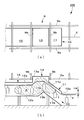
まず最初に図1を参照し、第1実施形態の山型乾燥炉について説明する。
First Embodiment First, a mountain-type drying furnace according to a first embodiment will be described with reference to FIG.
図1に示した第1実施形態の山型乾燥炉100は、エレベータの乗りかごのドアや側板、乗り場ホールのドアや三方枠等の意匠品1に吹き付けられた塗料を高温雰囲気内において硬化させるためのもので、出入口10から斜め上方に延びる傾斜部分11と、この傾斜部分11の上端に接続されて水平に延びる水平部分12と、この水平部分12の内部に熱気を供給するための燃焼装置6(図10を参照)とを備えている。
そして、傾斜部分11と水平部分12との間には、水平部分2の内部に滞留している熱気が傾斜部分11を通って出入口10から炉外に漏出することを防止する熱気漏出防止部分13が設けられている。
The mountain-
And between the
この熱気漏出防止部分13は、山型乾燥炉100の上方に設けられて水平に延びる梯子状の天井梁9の隙間を通って上方に突出する、傾斜部分11の天井11aおよび水平部分12の天井部分12aに連設された突出天井部分13aを有している。
具体的には、突出天井部分13aは、天井梁9の左右一対の縦梁9a,9a、および前後一対の横梁9b,9bによって囲まれる隙間を通って上方に延びている。
The hot air
Specifically, the
また、傾斜部分11の床面11bおよび水平部分12の床面11bには、突出天井部分に向かって上方に突出する突出床面部分13bが設けられている。
そして、この突出床面部分13bの上端部分13cは、出入口10の上端部分10aに対し、上下方向寸法H4の分だけ上方に位置している。
Further, the
The
このとき、意匠品1を吊り下げた状態で前後方向に移動するコンベアチェーン2は、出入口10から傾斜部分11に沿って斜め上方に延びるとともに、熱気漏出防止部分13の内部で水平に延びた後、水平部分12に向かって斜め下方に延び、次いで水平部分12に内部で水平に延びている。
なお、コンベアチェーン2のうち熱気漏出防止部分13の内部で水平に延びる部分は、吊り下げた意匠品1の下端が突出床面部分13bの上端部分13cに接触することがないように、その上下方向位置が定められている。
At this time, the
A portion of the
これにより、燃焼装置6から供給されて水平部分12の内部に滞留している熱気Aは、突出床面部分13bの上端部分13cより下方にある出入口10の上端部分10aへと、傾斜部分11に沿って降下することがないから、炉外に漏出することがない。
したがって、熱気Aが有している熱エネルギーが失われ、燃焼装置6で消費される燃料が増加してランニングコストがかさむことを、確実に防止することができる。
Thereby, the hot air A supplied from the
Therefore, it is possible to reliably prevent the heat energy possessed by the hot air A from being lost, increasing the fuel consumed by the
第2実施形態
次に図2を参照し、第2実施形態の山型乾燥炉について説明する。
Second Embodiment Next, a mountain-shaped drying furnace according to a second embodiment will be described with reference to FIG.
図2に示した本第2実施形態の山型乾燥炉110は、上述した第1実施形態の山型乾燥炉100における突出床面部分13bが、固定壁14に置き換えられている点で相違している。
The mountain-shaped
具体的に説明すると、水平部分12の床面12bには、突出天井部分13aに向かって上方に延びる固定壁14が突設されている。
また、この固定壁14は、コンベアチェーン2に吊り下げられて移動する意匠品1の下端にその上端部分14aが接触しないように、その上下方向の寸法が定められている。
そして、この固定壁14の上端部分14aは、出入口10の上端部分10aに対し、上下方向寸法H5の分だけ上方に位置している。
More specifically, the
The fixed
The
これにより、燃焼装置6から供給されて水平部分12の内部に滞留している熱気Aは、固定壁14の上端部分14aより下方にある出入口10の上端部分10aへと、傾斜部分11に沿って降下することがないから、炉外に漏出することがない。
したがって、熱気Aが有している熱エネルギーが失われ、燃焼装置6で消費される燃料が増加してランニングコストがかさむことを、確実に防止することができる。
また、水平部分12の床面12bに固定壁14を立設するという簡単な構造であるから、既存の山型乾燥炉をも容易に改修することかできる。
Thereby, the hot air A supplied from the
Therefore, it is possible to reliably prevent the heat energy possessed by the hot air A from being lost, increasing the fuel consumed by the
In addition, since the fixed
第3実施形態
次に図3および図4を参照し、第3実施形態の山型乾燥炉について説明する。
3rd Embodiment Next, with reference to FIG. 3 and FIG. 4, the mountain type drying furnace of 3rd Embodiment is demonstrated.
図3および図4に示した本第2実施形態の山型乾燥炉120は、上述した第2実施形態の山型乾燥炉110に対し、熱気漏出防止部分13が設けられていない点、および固定壁14が昇降可能な可動壁15に置き換えられている点で相違している。
The mountain-shaped
すなわち、天井梁9の横梁9bの前後方向間隔が狭いため、熱気漏出防止部分13を設けることができないのである。
これにより、意匠品1を吊り下げた状態で前後方向に移動するコンベアチェーン2は、出入口10から傾斜部分11に沿って斜め上方に延びた後、ただちに水平部分12の内部で水平に延びざるを得ず、吊り下げられている意匠品1の下端と水平部分12の床面12bとの間の上下方向の隙間を大きく取ることができない。
That is, since the space | interval of the front-back direction of the
As a result, the
そこで、本第3実施形態の山型乾燥炉120においては、水平部分12の床面12bから上方に突出した上昇位置(図3)と、意匠品1の移動を妨げない位置へと降下した降下位置(図4)との間で昇降自在な可動壁15が設けられている。
そして、この可動壁15を昇降させるために、水平部分12の下方にはエアシリンダ16が設けられている。
Therefore, in the mountain-shaped
An
可動壁15は、その上昇位置(図3)においては、水平部分12における意匠品1の移動経路のうち少なくともその下側部分を閉鎖するとともに、その上端部分15aは、出入口10の上端部分10aに対し上下方向寸法H6の分だけ上方に位置する。
これにより、燃焼装置6から供給されて水平部分12の内部に滞留している熱気Aは、可動壁15の上端部分15aより下方にある出入口10の上端部分10aへと、傾斜部分11に沿って降下することがないから、炉外に漏出することがない。
したがって、熱気Aが有している熱エネルギーが失われ、燃焼装置6で消費される燃料が増加してランニングコストがかさむことを、確実に防止することができる。
The
Thereby, the hot air A supplied from the
Therefore, it is possible to reliably prevent the heat energy possessed by the hot air A from being lost, increasing the fuel consumed by the
また、コンベアチェーン2に吊り下げられて移動する意匠品1が可動壁15に接近すると、図示されない制御手段の指令によってエアシリンダ16が短縮し、可動壁15が降下するから、意匠品1の作動を妨げることがない。
なお、エアシリンダ16が短縮するときのストロークは、可動壁15の上端15aが意匠品1の下端に接触しないような最小限の値に設定することが好ましい。
これにより、水平部分12の内部に滞留している熱気Aが傾斜部分11に向かって移動することを最小限に抑制することができる。
Further, when the
The stroke when the
Thereby, it is possible to minimize the movement of the hot air A staying in the
第4実施形態
次に図5および図6を参照し、第3実施形態の山型乾燥炉について説明する。
4th Embodiment Next, with reference to FIG. 5 and FIG. 6, the mountain type drying furnace of 3rd Embodiment is demonstrated.
図5および図6に示した本第4実施形態の山型乾燥炉130は、上述した第3実施形態の山型乾燥炉120に対し、昇降する可動壁15が、上下方向に延びる回動軸の回りに回動する回動壁20に置き換えられている点で相違している。
5 and 6, the
具体的に説明すると、この回動壁20は、水平部分12の左右の側壁12c,12dの内壁面に突設されて左右方向に延びる左右一対の固定壁21a,21bと、これらの固定壁21a,21bの先端にそれぞれ設けられて上下方向に延びる左右一対の回動軸22a,22bと、これらの回動軸22a,22bにその基端が固着された左右一対の回動部分23a,23bと、左右一対の回動軸22a,22bを駆動して回動させる回動手段24とを有している。
More specifically, the rotating
左右一対の回動部分23a,23bは、コンベアチェーン2に吊り下げられて移動する意匠品1が接近していないときは、図5および図6(a)に示したように、水平部分12における意匠品1の移動経路のうち少なくとも下側部分を閉鎖する閉鎖位置を取る。
このとき、回動壁20の上端は、出入口10の上端部分10aに対し、上下方向寸法H7の分だけ上方に位置している。
これにより、燃焼装置6から供給されて水平部分12の内部に滞留している熱気Aは、回動壁20の上端より下方にある出入口10の上端部分10aへと、傾斜部分11に沿って降下することがないから、炉外に漏出することがない。
したがって、熱気Aが有している熱エネルギーが失われ、燃焼装置6で消費される燃料が増加してランニングコストがかさむことを、確実に防止することができる。
The pair of left and right
At this time, the upper end of the
Thereby, the hot air A supplied from the
Therefore, it is possible to reliably prevent the heat energy possessed by the hot air A from being lost, increasing the fuel consumed by the
一方、コンベアチェーン2に吊り下げられて移動する意匠品1が回動壁20に接近すると、図示されない制御手段の指令によって回動手段24が作動し、左右一対の回動軸22a,22bをそれぞれ駆動して90度ず回動させる。
すると、左右一対の回動部分23a,23bは、図6(b)に示したように左右に開放するから、意匠品1の前後方向の移動を妨げることがない。
On the other hand, when the
Then, since the pair of left and right
なお、本第4実施形態は、上下方向に延びる左右一対の回動軸22a,22bを回動させる構造であるが、左右方向に水平に延びる一つの回動軸を回動させることにより、1つの回動部分体を水平部分12の床面12aに対して起伏する構造とすることもできる。
The fourth embodiment has a structure in which a pair of left and
第5実施形態
次に図7を参照し、第5実施形態の山型乾燥炉について説明する。
Fifth Embodiment Next, a mountain type drying furnace according to a fifth embodiment will be described with reference to FIG.
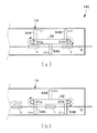
図7に示した本第5実施形態の山型乾燥炉140は、前後方向に延びる所定の循環経路に沿って循環する複数の閉鎖体を用いるものである。
The mountain-shaped
具体的に説明すると、水平部分12の内部には、意匠品1の移動方向に間隔を開けて配置されて上下方向に延びる前後一対の回転軸31a,31bが配設されている。
また、これらの回転軸31a,31bには、無端ベルト状の支持体32が巻装されて、前後一対の回転軸31a,31bの回りを図示時計方向に循環するようになっている。
さらに、この支持体32には、複数の閉鎖体33A,33B,33Cの基端がそれぞれ固着されて、水平部分12における意匠品1の移動経路の下側部分を閉鎖するようになっている。
加えて、水平部分12の下方には、前後一対の回転軸31a,31bを意匠品1の移動に連動させて回転駆動する循環駆動手段(図示せず)が設けられている。
More specifically, a pair of front and rear
Further, an endless belt-
Further, the base ends of the plurality of closing
In addition, below the
これにより、ある時点では、図7(a)に示したように、前後一対の意匠品1,1の間に1つの閉鎖体33Cが位置するとともに、その反対側には2つの閉鎖体33A,33Bが位置しており、水平部分12における意匠品1の移動経路の下側部分を閉鎖するようになっている。
これに対して、次の時点では、図7(b)に示したように、1つの意匠品1を2つの閉鎖体33C,33Bが前後方向に挟むとともに、その反対側には1つの閉鎖体33Aが位置しており、水平部分12における意匠品1の移動経路の下側部分を閉鎖するようになっている。
Thereby, at a certain point in time, as shown in FIG. 7 (a), one
On the other hand, at the next time point, as shown in FIG. 7 (b), one
このとき、これらの閉鎖体33A,33B,33Cの上端部は、図5に示した回動壁20の場合と同様に、出入口10の上端部分10aに対し、上下方向寸法H7の分だけ上方に位置している。
これにより、燃焼装置6から供給されて水平部分12の内部に滞留している熱気Aは、閉鎖体33A,33B,33Cの上端部より下方にある出入口10の上端部分10aへと、傾斜部分11に沿って降下することがないから、炉外に漏出することがない。
したがって、熱気Aが有している熱エネルギーが失われ、燃焼装置6で消費される燃料が増加してランニングコストがかさむことを、確実に防止することができる。
At this time, the upper end portions of these closing
Thereby, the hot air A supplied from the
Therefore, it is possible to reliably prevent the heat energy possessed by the hot air A from being lost, increasing the fuel consumed by the
第6実施形態
次に図8を参照し、第6実施形態の山型乾燥炉について説明する。
6th Embodiment Next, with reference to FIG. 8, the mountain type drying furnace of 6th Embodiment is demonstrated.
図8に示した本第6実施形態の山型乾燥炉150は、上述した第5実施形態の山型乾燥炉140と同様に、前後方向に延びる所定の循環経路に沿って循環する複数の閉鎖体を用いるものであるが、その回転軸が左右方向に水平に延びる点において相違している。
The mountain-shaped
具体的に説明すると、水平部分12の床面12bの近傍には、意匠品1の移動方向に間隔を開けて配置されて左右方向に水平に延びる前後一対の回転軸41a,41bが配設されている。
また、これらの回転軸41a,41bには、無端ベルト状の支持体42が巻装されて、前後一対の回転軸41a,41bの回りを図示反時計方向に循環するようになっている。
さらに、この支持体42には、複数の閉鎖体43A,43B,43C,43Dの基端がそれぞれ固着されて、水平部分12における意匠品1の移動経路の下側部分を閉鎖できるようになっている。
加えて、水平部分12の右側の側壁12cには、前後一対の回転軸41a,41bを意匠品1の移動に連動させて回転駆動する循環駆動手段44が設けられている。
More specifically, a pair of front and rear
Further, an endless belt-
Further, the base ends of the plurality of closing
In addition, the
これにより、図7(b)に示したように、意匠品1の前後方向の移動に連動して、複数の閉鎖体43A,43B,43C,43Dが次から次へと起立して、水平部分12における意匠品1の移動経路の下側部分を閉鎖する。
As a result, as shown in FIG. 7 (b), the plurality of closing
このとき、これらの閉鎖体43A,43B,43C,43Dの上端部は、図5に示した回動壁20の場合と同様に、出入口10の上端部分10aに対し、上下方向寸法H7の分だけ上方に位置している。
これにより、燃焼装置6から供給されて水平部分12の内部に滞留している熱気Aは、閉鎖体33A,33B,33Cの上端部より下方にある出入口10の上端部分10aへと、傾斜部分11に沿って降下することがないから、炉外に漏出することがない。
したがって、熱気Aが有している熱エネルギーが失われ、燃焼装置6で消費される燃料が増加してランニングコストがかさむことを、確実に防止することができる。
At this time, the upper end portions of these closing
Thereby, the hot air A supplied from the
Therefore, it is possible to reliably prevent the heat energy possessed by the hot air A from being lost, increasing the fuel consumed by the
1 意匠品
2 コンベアチェーン
3 前処理ブース
4 乾燥炉
5 塗装ブース
6 燃焼装置
10 出入口
11 傾斜部分
12 水平部分
13 熱気漏出防止部分
14 固定壁
15 可動壁
16 エアシリンダ(昇降手段)
20 回動壁
21 固定壁
22 回動軸
23 回動部分
24 回動手段
31 回転軸
32 支持体
33 閉鎖体
41 回転軸
42 支持体
43 閉鎖体
44 循環駆動手段
100 第1実施形態の山型乾燥炉
110 第2実施形態の山型乾燥炉
120 第3実施形態の山型乾燥炉
130 第4実施形態の山型乾燥炉
140 第5実施形態の山型乾燥炉
150 第6実施形態の山型乾燥炉
DESCRIPTION OF
DESCRIPTION OF
Claims (10)
出入口から斜め上方に延びる傾斜部分と、
この傾斜部分の上端に接続されて水平に延びる水平部分と、
この水平部分の内部に熱気を供給する熱気供給手段と、
前記水平部分の内部に滞留している熱気が前記傾斜部分を通って前記出入口から炉外に漏出することを防止する、前記傾斜部分と前記水平部分との接続部分に設けられた熱気漏出防止手段と、
を備えることを特徴とする山型乾燥炉。 A mountain-type drying furnace used for painting elevator design products,
An inclined portion extending obliquely upward from the doorway;
A horizontal portion connected to the upper end of the inclined portion and extending horizontally;
Hot air supply means for supplying hot air into the horizontal portion;
Hot air leakage prevention means provided at a connecting portion between the inclined portion and the horizontal portion, which prevents hot air staying in the horizontal portion from leaking out of the furnace through the inclined portion through the inclined portion. When,
A mountain drying oven characterized by comprising:
前記山型乾燥炉の上方に設けられている天井梁の隙間を通って上方に突出する、前記水平部分および前記傾斜部分の天井に連設された突出天井部分と、
前記水平部分および前記傾斜部分の床面から前記突出天井部分に向かって上方に突出する突出床面部分と、
を有していることを特徴とする請求項1に記載した山型乾燥炉。 The hot air leakage prevention means is
A projecting ceiling portion that projects upward through a gap between ceiling beams provided above the mountain-shaped drying furnace, and that is connected to the ceiling of the horizontal portion and the inclined portion;
A protruding floor surface portion protruding upward from the floor surface of the horizontal portion and the inclined portion toward the protruding ceiling portion;
The mountain-type drying furnace according to claim 1, wherein
前記水平部分および前記傾斜部分の上方に設けられている天井梁の隙間を通って上方に突出する、前記水平部分および前記傾斜部分の天井に連設された突出天井部分と、
前記水平部分の床面あるいは前記傾斜部分の床面に突設されて前記突出天井部分に向かって延びる固定壁と、
を有していることを特徴とする請求項1に記載した山型乾燥炉。 The hot air leakage prevention means is
A projecting ceiling portion connected to the ceiling of the horizontal portion and the inclined portion, which protrudes upward through a gap between ceiling beams provided above the horizontal portion and the inclined portion;
A fixed wall that protrudes from the floor surface of the horizontal portion or the floor surface of the inclined portion and extends toward the protruding ceiling portion;
The mountain-type drying furnace according to claim 1, wherein
前記水平部分の床面あるいは前記傾斜部分の床面から上方に突出して、前記水平部分あるいは前記傾斜部分における前記意匠品の移動経路の下側部分を閉鎖する上昇位置と、前記意匠品の移動を妨げない位置へと降下した降下位置との間で昇降自在な可動壁と、
この可動壁を駆動して昇降させる昇降手段と、
を有していることを特徴とする請求項1に記載した山型乾燥炉。 The hot air leakage prevention means is
Projecting upward from the floor surface of the horizontal portion or the inclined portion, and a rising position for closing a lower portion of the moving path of the design product in the horizontal portion or the inclined portion, and movement of the design product A movable wall that can be raised and lowered between a lowered position that has been lowered to an unobstructed position;
Elevating means for driving the movable wall to move up and down;
The mountain-type drying furnace according to claim 1, wherein
前記水平部分あるいは前記傾斜部分における前記意匠品の移動経路の下側部分を閉鎖する閉鎖位置と、前記意匠品の移動を妨げない開放位置との間で回動可能な回動壁と、
前記回動壁を駆動して前記閉鎖位置と前記開放位置との間で往復回動させる回動手段と、
を有しているすることを特徴とする請求項1に記載した山型乾燥炉。 The hot air leakage prevention means is
A rotating wall that is rotatable between a closed position that closes a lower portion of the moving path of the design product in the horizontal portion or the inclined portion, and an open position that does not hinder the movement of the design product,
Rotation means for driving the rotation wall to reciprocate between the closed position and the open position;
The mountain-type drying furnace according to claim 1, wherein
前記水平部分あるいは前記傾斜部分の内側に前記意匠品の移動方向に間隔を開けて配置された前後一対の回転軸と、
前記前後一対の回転軸に無端状に巻装されて前記前後一対の回転軸の回りを循環する支持手段と、
前記水平部分あるいは前記傾斜部分における前記意匠品の移動経路の下側部分を閉鎖する、前記支持手段にそれぞれその基端が固着された複数の閉鎖体と、
前記前後一対の回転軸を回転駆動することより、前記意匠品の移動に連動させて前記複数の閉鎖体を前後方向に循環移動させる循環駆動手段と、
を有していることを特徴とする請求項1に記載した山型乾燥炉。 The hot air leakage prevention means is
A pair of front and rear rotating shafts arranged at intervals in the moving direction of the design product inside the horizontal portion or the inclined portion;
A support means wound endlessly on the pair of front and rear rotating shafts and circulating around the pair of front and rear rotating shafts;
A plurality of closing bodies whose base ends are fixed to the support means, respectively, for closing a lower portion of the moving path of the design product in the horizontal portion or the inclined portion;
By rotating and driving the pair of front and rear rotating shafts, circulation driving means for circulating and moving the plurality of closing bodies in the front-rear direction in conjunction with the movement of the design product,
The mountain-type drying furnace according to claim 1, wherein
Priority Applications (1)
| Application Number | Priority Date | Filing Date | Title |
|---|---|---|---|
| JP2010172624A JP5832730B2 (en) | 2010-07-30 | 2010-07-30 | A mountain-type drying furnace used for painting elevator designs |
Applications Claiming Priority (1)
| Application Number | Priority Date | Filing Date | Title |
|---|---|---|---|
| JP2010172624A JP5832730B2 (en) | 2010-07-30 | 2010-07-30 | A mountain-type drying furnace used for painting elevator designs |
Publications (2)
| Publication Number | Publication Date |
|---|---|
| JP2012030181A true JP2012030181A (en) | 2012-02-16 |
| JP5832730B2 JP5832730B2 (en) | 2015-12-16 |
Family
ID=45844261
Family Applications (1)
| Application Number | Title | Priority Date | Filing Date |
|---|---|---|---|
| JP2010172624A Expired - Fee Related JP5832730B2 (en) | 2010-07-30 | 2010-07-30 | A mountain-type drying furnace used for painting elevator designs |
Country Status (1)
| Country | Link |
|---|---|
| JP (1) | JP5832730B2 (en) |
Cited By (1)
| Publication number | Priority date | Publication date | Assignee | Title |
|---|---|---|---|---|
| KR101514263B1 (en) * | 2013-05-14 | 2015-04-23 | 한국전기연구원 | Infrared drying device for painting |
Citations (6)
| Publication number | Priority date | Publication date | Assignee | Title |
|---|---|---|---|---|
| JPS60173893U (en) * | 1984-04-24 | 1985-11-18 | マツダ株式会社 | Paint drying oven |
| JPS63182068A (en) * | 1987-01-24 | 1988-07-27 | Nippon Paint Co Ltd | Horizontal oven |
| JPH04114762A (en) * | 1990-09-05 | 1992-04-15 | Setsuo Tate | Drying oven |
| JPH10137658A (en) * | 1996-11-13 | 1998-05-26 | Nissan Motor Co Ltd | Heating furnace for baking coating |
| JPH1142445A (en) * | 1997-07-28 | 1999-02-16 | Toshiba Corp | Coating line for elevator |
| JP2003290705A (en) * | 2002-03-29 | 2003-10-14 | Toshiba Elevator Co Ltd | Method of coating elevator designed article |
-
2010
- 2010-07-30 JP JP2010172624A patent/JP5832730B2/en not_active Expired - Fee Related
Patent Citations (6)
| Publication number | Priority date | Publication date | Assignee | Title |
|---|---|---|---|---|
| JPS60173893U (en) * | 1984-04-24 | 1985-11-18 | マツダ株式会社 | Paint drying oven |
| JPS63182068A (en) * | 1987-01-24 | 1988-07-27 | Nippon Paint Co Ltd | Horizontal oven |
| JPH04114762A (en) * | 1990-09-05 | 1992-04-15 | Setsuo Tate | Drying oven |
| JPH10137658A (en) * | 1996-11-13 | 1998-05-26 | Nissan Motor Co Ltd | Heating furnace for baking coating |
| JPH1142445A (en) * | 1997-07-28 | 1999-02-16 | Toshiba Corp | Coating line for elevator |
| JP2003290705A (en) * | 2002-03-29 | 2003-10-14 | Toshiba Elevator Co Ltd | Method of coating elevator designed article |
Cited By (1)
| Publication number | Priority date | Publication date | Assignee | Title |
|---|---|---|---|---|
| KR101514263B1 (en) * | 2013-05-14 | 2015-04-23 | 한국전기연구원 | Infrared drying device for painting |
Also Published As
| Publication number | Publication date |
|---|---|
| JP5832730B2 (en) | 2015-12-16 |
Similar Documents
| Publication | Publication Date | Title |
|---|---|---|
| JP6432982B2 (en) | Repainting equipment | |
| JP4505736B2 (en) | Painting machine | |
| KR20140009154A (en) | Process chamber with device for injecting gaseous fluid | |
| BR122020014269B1 (en) | STATIONS AND FACILITIES FOR SURFACE TREATMENT OF OBJECTS | |
| JP5363082B2 (en) | Work cleaning device | |
| JP5832730B2 (en) | A mountain-type drying furnace used for painting elevator designs | |
| KR101643154B1 (en) | spray type painting installation | |
| CN204866322U (en) | Stealthy tectorial membrane agent automatic spraying production line | |
| KR101052009B1 (en) | Powder coating device | |
| KR102239571B1 (en) | A apparatus for drying the coated film | |
| KR101499425B1 (en) | Anti-vibration rubber coating device automatically | |
| WO2012175579A1 (en) | Plant for painting | |
| KR200284370Y1 (en) | The oven type of painting system for the piping of ship | |
| CN206926361U (en) | Printed panel drying unit | |
| US3438138A (en) | Apparatus for drying a wet coating on a surface | |
| JP2003329366A (en) | Coating drying furnace | |
| KR102603278B1 (en) | Automatic surface treatment method for processing objects | |
| KR102475531B1 (en) | Carriage shifter in drier for automatic painting system | |
| JPS63182068A (en) | Horizontal oven | |
| US3609876A (en) | Method for drying a wet coating on a surface | |
| CN112295810B (en) | Water paint vibrates dry film production line | |
| RU113179U1 (en) | DEVICE FOR APPLICATION OF PROTECTIVE COATING ON SPRING PRODUCTS | |
| SU1741921A1 (en) | Apparatus for painting and drying large-size articles | |
| TWI716899B (en) | Colorizing method | |
| KR20170067994A (en) | Hot-air circulating type drying maching with a 2nd layer conveyor structure |
Legal Events
| Date | Code | Title | Description |
|---|---|---|---|
| A621 | Written request for application examination |
Free format text: JAPANESE INTERMEDIATE CODE: A621 Effective date: 20121004 |
|
| A977 | Report on retrieval |
Free format text: JAPANESE INTERMEDIATE CODE: A971007 Effective date: 20131114 |
|
| A131 | Notification of reasons for refusal |
Free format text: JAPANESE INTERMEDIATE CODE: A131 Effective date: 20140107 |
|
| A521 | Written amendment |
Free format text: JAPANESE INTERMEDIATE CODE: A523 Effective date: 20140307 |
|
| A131 | Notification of reasons for refusal |
Free format text: JAPANESE INTERMEDIATE CODE: A131 Effective date: 20140812 |
|
| A521 | Written amendment |
Free format text: JAPANESE INTERMEDIATE CODE: A523 Effective date: 20141014 |
|
| A131 | Notification of reasons for refusal |
Free format text: JAPANESE INTERMEDIATE CODE: A131 Effective date: 20150515 |
|
| A521 | Written amendment |
Free format text: JAPANESE INTERMEDIATE CODE: A523 Effective date: 20150710 |
|
| TRDD | Decision of grant or rejection written | ||
| A01 | Written decision to grant a patent or to grant a registration (utility model) |
Free format text: JAPANESE INTERMEDIATE CODE: A01 Effective date: 20151002 |
|
| A61 | First payment of annual fees (during grant procedure) |
Free format text: JAPANESE INTERMEDIATE CODE: A61 Effective date: 20151028 |
|
| R150 | Certificate of patent or registration of utility model |
Ref document number: 5832730 Country of ref document: JP Free format text: JAPANESE INTERMEDIATE CODE: R150 |
|
| LAPS | Cancellation because of no payment of annual fees |