JP2012024959A - Method for confirming attachment position of holding member, holding member, and recording device - Google Patents
Method for confirming attachment position of holding member, holding member, and recording device Download PDFInfo
- Publication number
- JP2012024959A JP2012024959A JP2010163656A JP2010163656A JP2012024959A JP 2012024959 A JP2012024959 A JP 2012024959A JP 2010163656 A JP2010163656 A JP 2010163656A JP 2010163656 A JP2010163656 A JP 2010163656A JP 2012024959 A JP2012024959 A JP 2012024959A
- Authority
- JP
- Japan
- Prior art keywords
- holding member
- recording medium
- roll paper
- recording
- opening
- Prior art date
- Legal status (The legal status is an assumption and is not a legal conclusion. Google has not performed a legal analysis and makes no representation as to the accuracy of the status listed.)
- Granted
Links
Images
Classifications
-
- B—PERFORMING OPERATIONS; TRANSPORTING
- B41—PRINTING; LINING MACHINES; TYPEWRITERS; STAMPS
- B41J—TYPEWRITERS; SELECTIVE PRINTING MECHANISMS, i.e. MECHANISMS PRINTING OTHERWISE THAN FROM A FORME; CORRECTION OF TYPOGRAPHICAL ERRORS
- B41J11/00—Devices or arrangements of selective printing mechanisms, e.g. ink-jet printers or thermal printers, for supporting or handling copy material in sheet or web form
- B41J11/0045—Guides for printing material
Landscapes
- Ink Jet (AREA)
- Handling Of Continuous Sheets Of Paper (AREA)
Abstract
【課題】保持部材が所定の位置に取り付けられているか否かを確実に確認できる保持部材の取付位置の確認方法、保持部材、及び記録装置を提供する。
【解決手段】媒体支持面で被記録媒体の裏面を吸着保持する媒体支持部と、被記録媒体の搬送方向と略直交する方向の側縁部において被記録媒体を覆って保持する保持部材と、を備えた記録装置における被記録媒体に対する保持部材の取付位置の確認方法である。被記録媒体の幅方向におけるエッチ又は保持部材に形成された被記録媒体に対する位置決め用の開口部の幅方向におけるエッチを検出する検出部が被記録媒体の幅方向に沿って保持部材側に走査する位置検出工程を有する。この位置検出工程は、第1のエッチを検出する第1の検出ステップS1と、第2のエッチを検出する第2の検出ステップS2と、第3のエッチを検出する第3の検出ステップS3と、を含む。
【選択図】図6A method for confirming a mounting position of a holding member, a holding member, and a recording apparatus capable of reliably confirming whether or not the holding member is mounted at a predetermined position.
A medium support unit that sucks and holds a back surface of a recording medium with a medium support surface, a holding member that covers and holds the recording medium at a side edge in a direction substantially orthogonal to the conveyance direction of the recording medium, The method for confirming the attachment position of the holding member with respect to the recording medium in the recording apparatus comprising A detection unit that detects the etching in the width direction of the recording medium or the etching in the width direction of the opening for positioning with respect to the recording medium formed on the holding member scans the holding member side along the width direction of the recording medium. A position detecting step; This position detection step includes a first detection step S1 for detecting a first etch, a second detection step S2 for detecting a second etch, and a third detection step S3 for detecting a third etch. ,including.
[Selection] Figure 6
Description
本発明は、保持部材の取付位置の確認方法、保持部材、及び記録装置に関するものである。 The present invention relates to a method for confirming a mounting position of a holding member, a holding member, and a recording apparatus.
従来では、被記録媒体において、何らかの原因によってカールが生じた場合の対策として、被記録媒体の両側部に薄い樹脂シートからなる押さえ部材(保持部材)を設け、押さえ部材とプラテンの媒体支持面との間に形成された隙間に被記録媒体を挿入することにより、カールに起因する不具合を回避する技術が提供されている(例えば、特許文献1参照)。 Conventionally, as a countermeasure when curling occurs for some reason in a recording medium, a pressing member (holding member) made of a thin resin sheet is provided on both sides of the recording medium, and the pressing member and the medium support surface of the platen There is provided a technique for avoiding a problem caused by curling by inserting a recording medium into a gap formed between the two (see, for example, Patent Document 1).
しかしながら、上述したような従来技術には、以下のような問題が存在する。
押さえ部材の取り付け時に位置ズレが生じると、押さえ部材が記録ヘッドの記録領域に重なることで記録動作を妨げてしまう、或いは押さえ部材が被記録媒体を確実に押さえることができないといった問題を生じさせてしまう。
However, the following problems exist in the conventional technology as described above.
If a displacement occurs when the pressing member is attached, the pressing member may overlap the recording area of the recording head, thereby hindering the recording operation, or the pressing member cannot reliably press the recording medium. End up.
本発明はこのような事情に鑑みてなされたものであって、保持部材が所定の位置に取り付けられているか否かを確実に確認できる保持部材の取付位置の確認方法、保持部材、及び記録装置を提供することを目的とする。 The present invention has been made in view of such circumstances, and a method for confirming a mounting position of a holding member, a holding member, and a recording apparatus that can surely confirm whether or not the holding member is mounted at a predetermined position. The purpose is to provide.
上記の課題を解決するために、本発明の保持部材の取付位置の確認方法は、媒体支持面で被記録媒体の裏面を吸着保持する媒体支持部と、前記被記録媒体の搬送方向と略直交する方向の側縁部において前記被記録媒体を覆って保持する保持部材と、を備えた記録装置における前記被記録媒体に対する前記保持部材の取付位置の確認方法であって、前記被記録媒体の幅方向におけるエッチ又は前記保持部材に形成された前記被記録媒体に対する位置決め用の開口部の前記幅方向におけるエッチを検出する検出部が前記被記録媒体の幅方向に沿って前記保持部材側に走査する位置検出工程を有し、前記位置検出工程は、第1のエッチを検出する第1の検出ステップと、前記第1のエッチを検出した場合において、第2のエッチを検出する第2の検出ステップと、前記第2のエッチを検出した場合において、第3のエッチを検出する第3の検出ステップと、を含むことを特徴とする。 In order to solve the above-described problems, the method for confirming the mounting position of the holding member according to the present invention includes a medium support portion that sucks and holds the back surface of the recording medium with the medium support surface, and a substantially orthogonal direction to the conveyance direction of the recording medium. And a holding member that covers and holds the recording medium at a side edge portion in a direction in which the recording medium is attached, and a method for confirming an attachment position of the holding member with respect to the recording medium in a recording apparatus comprising: a width of the recording medium; The detection unit for detecting the etching in the direction or the etching in the width direction of the opening for positioning the recording medium formed on the holding member scans the holding member side along the width direction of the recording medium. A first detection step for detecting a first etch, and a second detection for detecting a second etch when the first etch is detected. A step, in the case of detecting the second etch, characterized in that it comprises a third detection step of detecting a third etch, an.
本発明の保持部材の取付方法によれば、第1〜第3の検出ステップにより被記録媒体のエッチ及び開口部のエッチを検出することができ、検出したエッチに基づき、被記録媒体に対する保持部材の位置が良好であるか否かを検出することができる。また、保持部材は開口部以外の領域にて被記録媒体の側縁部を覆っているので、被記録媒体の搬送する場合であっても該被記録媒体が保持部材に引っ掛かる等の不具合が生じることを防止できる。 According to the mounting method of the holding member of the present invention, it is possible to detect the etching of the recording medium and the etching of the opening by the first to third detection steps, and based on the detected etching, the holding member for the recording medium It is possible to detect whether the position of is good. In addition, since the holding member covers the side edge of the recording medium in a region other than the opening, even when the recording medium is transported, a problem such as the recording medium being caught by the holding member occurs. Can be prevented.
また、上記保持部材の取付位置の確認方法においては、前記検出部は、前記保持部材における前記被記録媒体の搬送方向上流側において前記位置検出工程を行うのが好ましい。
この構成によれば、被記録媒体の搬送方向上流側において保持部材の取付位置を確認できるので、取付位置不良により良好に保持部材により保持されていない被記録媒体が記録装置による記録領域に搬送されてしまうのを防止できる。
In the method for confirming the mounting position of the holding member, it is preferable that the detection unit performs the position detection step on the upstream side of the recording medium in the transport direction of the recording medium.
According to this configuration, since the attachment position of the holding member can be confirmed on the upstream side in the conveyance direction of the recording medium, the recording medium that is not favorably held by the holding member due to a bad attachment position is conveyed to the recording area by the recording apparatus. Can be prevented.
本発明の保持部材は、媒体支持面で被記録媒体の裏面を吸着保持する媒体支持部を備えた記録装置に用いられ、前記被記録媒体の搬送方向と略直交する方向の側縁部において前記被記録媒体を覆って保持する保持部材であって、前記被記録媒体の端部に対する位置合わせを行うための位置合わせマークと、前記位置合わせマークに隣接して配置される開口部と、を有することを特徴とする。 The holding member of the present invention is used in a recording apparatus including a medium support unit that sucks and holds a back surface of a recording medium with a medium support surface, and the side member in a direction substantially perpendicular to the conveyance direction of the recording medium. A holding member that covers and holds the recording medium, and includes an alignment mark for aligning with an end portion of the recording medium, and an opening disposed adjacent to the alignment mark. It is characterized by that.
本発明の保持部材によれば、位置合わせマークを参照しつつ、開口部内に被記録媒体の端部を配置することで被記録媒体との位置合わせ作業を容易に行うことができる。また、例えば開口部を介して被記録媒体の端部を検出することで、被記録媒体に対する保持部材の取付位置の確認を容易に行うことができる。また、保持部材は開口部以外の領域において被記録媒体の側縁部を覆っているので、被記録媒体の搬送時に該被記録媒体が保持部材に引っ掛る等の不具合を生じることがない。 According to the holding member of the present invention, the positioning operation with the recording medium can be easily performed by arranging the end portion of the recording medium in the opening while referring to the alignment mark. Further, for example, by detecting the end of the recording medium through the opening, it is possible to easily confirm the mounting position of the holding member with respect to the recording medium. In addition, since the holding member covers the side edge of the recording medium in a region other than the opening, there is no problem such that the recording medium is caught by the holding member when the recording medium is transported.
上記保持部材においては、前記位置合わせマークは、前記保持部材の延在方向に沿って延びる一対の直線部からなるのが好ましい。
この構成によれば、例えば、一対の直線部の間に被記録媒体の端部を配置するように被記録媒体に対する保持部材の位置合わせ作業を行うことで、位置合わせ作業を効率的に行うことができる。
In the holding member, the alignment mark preferably includes a pair of linear portions extending along the extending direction of the holding member.
According to this configuration, for example, the alignment work can be efficiently performed by performing the alignment operation of the holding member with respect to the recording medium so that the end of the recording medium is disposed between the pair of linear portions. Can do.
上記保持部材においては、略矩形状からなる前記開口部は前記一対の直線部の延在方向における一端に配置されており、該開口部は前記一対の直線部の中心線に対して対称となっているのが望ましい。
この構成によれば、開口部の中心に被記録媒体の端部が一致すると一対の直線部間に被記録媒体の端部が配置されることとなるので、開口部及び一対の直線部を参照することで保持部材による位置合わせ作業を効率的に行うことができる。
In the holding member, the opening having a substantially rectangular shape is disposed at one end in the extending direction of the pair of linear portions, and the opening is symmetric with respect to the center line of the pair of linear portions. It is desirable.
According to this configuration, when the end of the recording medium coincides with the center of the opening, the end of the recording medium is disposed between the pair of linear portions, so refer to the opening and the pair of linear portions. By doing so, the alignment work by the holding member can be performed efficiently.
本発明の記録装置は、媒体支持面で被記録媒体の裏面を吸着保持する媒体支持部と、前記被記録媒体の搬送方向と略直交する方向の側縁部において前記被記録媒体を覆って保持する上記保持部材と、前記開口部を用いて前記被記録媒体の側縁部を検出し、前記保持部材との前記被記録媒体との位置関係を検出する検出部と、を備えることを特徴とする。 The recording apparatus of the present invention covers and holds the recording medium at a medium supporting portion that sucks and holds the back surface of the recording medium with a medium supporting surface, and a side edge portion in a direction substantially perpendicular to the conveyance direction of the recording medium. And a detection unit that detects a side edge portion of the recording medium using the opening and detects a positional relationship between the holding member and the recording medium. To do.
本発明の記録装置によれば、保持部材の開口部を用いて被記録媒体の端部及び保持部材の開口部との位置を検出することができる。これにより、被記録媒体に対する保持部材の位置を良好に検出することができ、該検出結果に基づいて保持部材の位置調整を行うことで保持部材を被記録媒体に対して所定の位置に取り付けることができる。 According to the recording apparatus of the present invention, the positions of the end of the recording medium and the opening of the holding member can be detected using the opening of the holding member. Thereby, the position of the holding member with respect to the recording medium can be detected well, and the holding member is attached to the recording medium at a predetermined position by adjusting the position of the holding member based on the detection result. Can do.
以下、本発明の記録装置の実施の形態を、図1ないし図7を参照して説明する。
なお、以下の実施の実施形態は、本発明の一態様を示すものであり、この発明を限定するものではなく、本発明の技術的思想の範囲内で任意に変更可能である。また、以下の図面においては、各構成をわかりやすくするために、実際の構造と各構造における縮尺や数等を異ならせている。
Hereinafter, an embodiment of a recording apparatus of the present invention will be described with reference to FIGS.
The following embodiment shows one aspect of the present invention and does not limit the present invention, and can be arbitrarily changed within the scope of the technical idea of the present invention. Moreover, in the following drawings, in order to make each configuration easy to understand, the actual structure is different from the scale and number of each structure.
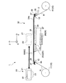
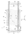
図1に示すのは、本発明に係る「記録装置」の一例として示される「液体噴射装置」としてのインクジェットプリンター(以下「プリンター」と言う)1の全体の概略を示す側面図である。また、図2に示すのはプリンター1に係る平面図である。
FIG. 1 is a side view showing an outline of an entire inkjet printer (hereinafter referred to as “printer”) 1 as a “liquid ejecting apparatus” shown as an example of a “recording apparatus” according to the present invention. FIG. 2 is a plan view of the
ここで、液体噴射装置とは、液体噴射ヘッドとしての記録ヘッドから記録紙等の被記録材へインクを噴射して被記録材への記録を実行するインクジェット式噴射装置や、複写機及びファクシミリ等の記録装置に用いられ、インクに代えて特定の用途に対応する液体を前述した記録ヘッドに相当する液体噴射ヘッドから、被記録材に相当する被噴射材に噴射して、液体を被噴射材に付着させて記録する記録装置に含まれるものである。 Here, the liquid ejecting apparatus is an ink jet ejecting apparatus that performs recording on a recording material by ejecting ink from a recording head as a liquid ejecting head to a recording material such as recording paper, a copying machine, a facsimile, or the like. In this recording apparatus, a liquid corresponding to a specific application is ejected from the liquid ejecting head corresponding to the recording head to the ejected material corresponding to the recording material instead of the ink, and the liquid is ejected. It is included in a recording apparatus for recording by attaching to the recording medium.
またさらに、液体噴射ヘッドとしては、前述した記録ヘッド以外に、液晶ディスプレイ等のカラーフィルタ製造に用いられる色材噴射ヘッド、有機ELディスプレイや面発光ディスプレイ(FED)等の電極形成に用いられる電極材(導電ペースト)噴射ヘッド、バイオチップ製造に用いられる生体有機物噴射ヘッド、精密ピペットとしての試料を噴射する試料噴射ヘッド等が挙げられる。 Further, as the liquid ejecting head, in addition to the recording head described above, a color material ejecting head used for manufacturing a color filter such as a liquid crystal display, an electrode material used for forming an electrode such as an organic EL display or a surface emitting display (FED) (Conductive paste) A jet head, a bio-organic matter jet head used for biochip manufacturing, a sample jet head for jetting a sample as a precision pipette, and the like.
図1および図2に示す如く、プリンター1は、給送部10と、記録部20と、排出部40とを備えている。このうち、給送部10は、被噴射媒体および被記録媒体の一例であるロール紙Rを記録部20へ給送することができるように設けられている。
具体的には、ロール媒体ホルダ11を有し、ロール媒体ホルダ11がロール状のロール紙Rを保持している。そして、ロール状のロール紙Rを回動させることにより、送り方向下流側(搬送方向;Y軸の矢印方向)の記録部20へ第1ローラー12を介してロール状態を解いた状態のロール紙Rを給送することができるように構成されている。
尚、本実施形態では、被記録媒体の一例としてロール紙Rを挙げて説明するが、単票紙やフィルム材でもよいのは勿論である。
As shown in FIGS. 1 and 2, the
Specifically, the
In the present embodiment, the roll paper R will be described as an example of the recording medium, but it is needless to say that a cut sheet or a film material may be used.
また、記録部20は、給送部10から送られたロール紙Rに対して液体(流体)の一例であるインクを吐出して記録を実行することができるように設けられている。
具体的には、媒体支持部であるプラテン24と、キャリッジ21と、記録ヘッド22と、カール押さえ手段30とを有している。このうち、プラテン24は、支持面(媒体支持面)24aにおいてロール紙Rを裏面から支持することができるように設けられている。
Further, the
Specifically, it includes a
また、キャリッジ21は、プラテン24と対向し、図示しない第1ガイド軸に案内されながら、図示しないキャリッジモーターの動力によって、ロール紙Rの送り方向Yに移動することができるように設けられている。
尚、図1に示すのは、プラテン24より送り方向上流側へ退避した状態である。キャリッジ21がプラテン24より上流側へ移動可能に設けられているのは、後述するカール押さえ部材31の取り付け・取り外しおよび幅方向Xへの移動をオペレーターが容易に行うことができるようにするためである。
The
FIG. 1 shows a state where the
記録ヘッド22は、キャリッジ21に設けられ、送り方向Yにおいてキャリッジ21と一体に移動することができるように設けられている。さらに、記録ヘッド22は、ロール紙Rの幅方向であるX方向において、キャリッジ21に対して相対的に移動することができるように構成されている。具体的には、図示しない第2ガイド軸に案内されながら、図示しない記録ヘッドモーターの動力によって、幅方向Xに移動することができるように設けられている。即ち、記録ヘッド22は、プラテン24と対向する範囲において、送り方向Yおよび幅方向Xへ2次元で移動することができるように構成されている。そして、記録ヘッド22におけるプラテン24と対向する面に設けられたノズル列23からインクを吐出することにより、ロール紙Rに対する記録処理を実行することができる。
The
またさらに、プラテン24には、吸引手段28、圧力室27、複数の吸引孔26、26…および加熱手段25が設けられている。このうち、吸引手段28は、圧力室27の内部の空気を吸引して負圧にすることができるように設けられている。具体的には、一例である軸流ファン29を有し、軸流ファン29が圧力室27の内部の空気を吸引するように構成されている。
Further, the
また、圧力室27は、プラテン24におけるロール紙Rを支持する側である鉛直方向上方(Z軸の矢印方向)に設けられた複数の吸引孔26、26…と繋がっている。従って、吸引手段28の吸引により、複数の吸引孔26、26…を介してプラテン24の上方の空気を吸引することができる。尚、本実施形態では、吸引孔26、26…をプラテン24の全領域に設けたが、少なくとも、ロール紙Rの両側側縁および一対のカール押さえ部材31,32と対向する範囲に設ければよい。
Further, the
また、加熱手段25は、プラテン24上のロール紙Rを加熱することができるように設けられている。記録実行に伴い、ロール紙Rの表面に着弾したインクの乾燥を促進するためである。具体的には、一例であるニクロム線25aを有している。ニクロム線25aは、プラテン24全領域の内部に、プラテン24の上面から一定の距離となるように配設されている。そして、通電されることにより、ニクロム線25a自体が発熱し、プラテン24を介して接触しているプラテン24上のロール紙Rの裏面へ熱を伝導することができる。
The heating means 25 is provided so that the roll paper R on the
ここで、ニクロム線25aは、プラテン24の全領域に設けられているので、プラテン24の全領域において発熱することができる。そして、プラテン24上は、凹凸のない滑らかな面となっているので、プラテン24の上面は、ロール紙Rと均一に接触することができる。また、ニクロム線25aからプラテン24の上面までの距離は一定である。従って、プラテン24上のロール紙Rに対して熱を均一に伝導することができる。即ち、ロール紙Rを均一に温めることができる。
Here, since the
その結果、ロール紙Rの同じ箇所にインクを重ねて吐出する所謂、重ね打ちを実行してもインクが濁ったり、滲んだりする虞がない。即ち、重ねてインクを吐出するときまでに、前に吐出したインクを既に乾燥させておくことができるので、重ね打ちを実行してもインクが濁ったり、滲んだりする虞がない。また、記録時にロール紙Rに着弾したインクをすぐに乾燥させることができるので、後述する排出部40において巻き取られても、ロール紙Rの表面のインクが先行するロール紙Rの裏面に付着する虞がない。
As a result, there is no possibility that the ink may become cloudy or bleed even if so-called overstrike is performed in which the ink is ejected in the same location on the roll paper R. In other words, since the previously ejected ink can be dried by the time when the ink is ejected in layers, there is no possibility that the ink will become cloudy or bleed even if the overstrike is executed. Further, since the ink that has landed on the roll paper R at the time of recording can be dried immediately, the ink on the surface of the roll paper R adheres to the back surface of the preceding roll paper R even if it is taken up by the
カール押さえ手段30は、ロール紙Rの幅方向の側縁部R1を押さえて保持することにより、ロール紙Rの側縁部R1がカールしてプラテン24から離間する力である所謂、浮き上がり力に対抗する。そして、ロール紙Rの側縁部R1の浮き上がりを防止するように構成されている。具体的には、カール押さえ手段30は、プラテン24と、可撓性素材で一例としてフィルム状に形成された一対のカール押さえ部材(保持部材)31、32と、複数の吸引孔26、26…と、吸引手段28とから構成されている。
The curl pressing means 30 presses and holds the side edge R1 in the width direction of the roll paper R, so that the side edge R1 of the roll paper R curls and separates from the
詳しくは、後述するようにロール紙Rの側縁部R1において、プラテン24と、カール押さえ部材31,32と、ロール紙Rとによって密閉空間A(図3(a)参照)が構成される。そして、吸引孔26、26…を介して吸引手段28が該密閉空間Aの内部の空気を吸引することにより、カール押さえ部材31,32がロール紙Rの側縁部R1を上から押さえ付けるように作用する。
Specifically, as will be described later, the sealed space A (see FIG. 3A) is configured by the
本実施例では、カール押さえ部材31,32は、柔軟性および可撓性を有した帯状の薄いフィルム状に形成されている。ヤング率は10000MPa(メガパスカル)以下であり、厚みは0.5mm以下である。素材は、例えば「ポリイミド」等が挙げられる。
In this embodiment, the
図1及び図2に示すように、プラテン24より送り方向(搬送方向)上流側(−Y側)には、第1カール押さえ取り付け部35が配設されている。一方、プラテン24より送り方向下流側(+Y側)には、第2カール押さえ取り付け部36が配設されている。
As shown in FIGS. 1 and 2, a first curl pressing
一対のカール押さえ部材31、32の一端は、固定用ピン37および固定用補助部材38によって、第1カール押さえ取り付け部35に取り付けられている。本実施形態では、カール押さえ部材31の一端が第1カール押さえ取り付け部35において幅方向Xへ延設された第1長穴部35aに、固定用ピン37が嵌合することにより、X方向の位置が調整可能な状態となっている。カール押さえ部材32の一端が第1カール押さえ取り付け部35に固定されている。
One end of the pair of
一方、一対のカール押さえ部材31、32の他端は、前記一端と同様に固定用ピン37および固定用補助部材38によって、第2カール押さえ取り付け部36に取り付けられている。第2カール押さえ取り付け部36は、プリンター1の基体部2に固定されている。
カール押さえ部材31の他端は、第2カール押さえ取り付け部36において幅方向Xへ延設された第2長穴部36aに、固定用ピン37…が嵌合することにより、X方向の位置が調整可能な状態で取り付けられる。また、カール押さえ部材32の他端が第2カール押さえ取り付け部36に固定されている。このように本実施形態では、カール押さえ部材31が第1長穴部35a及び第2長穴部36aに沿って移動することで、一対のカール押さえ部材31、32の間隔を種々の記録部20の幅に対応可能としている。
On the other hand, the other ends of the pair of
The other end of the
続いて、カール押さえ手段31、32の具体的な構成及びその作用について説明する。
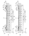
図3は、プラテン24においてX方向に沿って断面した図であり、図3(a)はカール押さえ部材をロール紙の側縁部に乗せたときに、密閉空間が形成された様子を示す図であり、図3(b)は吸引手段によって密閉空間が略消滅し、ロール紙の側端の浮き上がりが無くなった様子を示す図である。
Next, the specific configuration and operation of the curl pressing means 31 and 32 will be described.
FIG. 3 is a cross-sectional view of the
図3(a),(b)に示すように、各カール押さえ部材31、32は、プラテン24上にロール紙Rとは間隔をあけて配置されるベース部51と、ベース部51上に設けられベース部51から支持面24a上に延出してロール紙Rの側縁部R1を被覆し、支持面24aとの間でロール紙Rを保持する保持部材52とを有している。ベース部51はロール紙Rと略同じ厚みに設定されており、保持部材52がロール紙Rを保持する際に当該保持部材52の下面とロール紙Rの上面とが面一になるようにしている。
As shown in FIGS. 3A and 3B, the
図3(a)に示すように、ロール紙Rがプラテン24上に設けられた状態でオペレーターが一対のカール押さえ部材31、32の位置を幅方向Xにおいて、ロール紙Rの側縁部R1と対向する位置に合わせる。具体的には、固定用ピン37…を緩め、オペレーターがカール押さえ部材31を第1長穴部35a及び第2長穴部36aに沿って移動することで、一対のカール押さえ部材31、32の間隔をロール紙Rの紙幅に合わせる。そして、カール押さえ部材31がロール紙Rの側縁部R1の上に乗るように配置する。なお、本実施形態に係るカール押さえ部材32は、ロール紙Rがセットされると該ロール紙Rの側縁部R1の上に乗るように固定されている。
As shown in FIG. 3A, the operator places the position of the pair of
このとき、カール押さえ部材31、32の中、ベース部51はロール紙Rと離間し、保持部材52はロール紙Rの側縁部R1を覆うように配置する。その後、固定用ピン37…を締めて固定する。
At this time, in the
ロール紙Rの側縁部R1は、加熱手段25により加熱され、カールする傾向にある。従って、側縁部R1は、上方へ浮き上がるようにカールする。
そこで、一対のカール押さえ部材31、32の保持部材52をロール紙Rの側縁部R1に乗せて、プラテン24、ロール紙Rの側縁部R1近傍および保持部材52によって送り方向Yから視て三角形の密閉空間Aを構成する。
The side edge R1 of the roll paper R is heated by the heating means 25 and tends to curl. Accordingly, the side edge R1 curls so as to float upward.
Therefore, the holding
即ち、プラテン24を底辺、ロール紙Rの側縁部R1近傍を一の斜辺、保持部材52を他の斜辺とした閉じられた三角形の密閉空間Aである。
ここで、一対のカール押さえ部材31、32には、下方へ押さえる力が多少なりとも作用しているので、一対のカール押さえ部材31,32の一の側端E1をプラテン24と少なくとも線接触させることができる。同様に、一対のカール押さえ部材31,32の他の側端E2側の面をロール紙Rの側縁部R1と少なくとも線接触させることができる。
That is, it is a closed triangular sealed space A with the
Here, the pair of
また、複数の吸引孔26、26…は、プラテン24上の領域において、少なくともロール紙Rの側縁部R1、R1およびカール押さえ部材31,32と対向する領域に設けられている。従って、吸引手段28は、密閉空間Aの空気を、吸引孔26、26…を介して吸引することができる。
Further, the plurality of suction holes 26, 26... Are provided in the region on the
図3(b)に示したように、吸引孔26、26…を介して密閉空間Aの空気が吸引されると、密閉空間Aの内部が負圧となる。従って、ロール紙Rの両側側縁部R1、R1および一対のカール押さえ部材31,32は、プラテン24の支持面24aに密に接触した状態となる。即ち、ロール紙Rは、側縁部R1も含めてプラテン24の支持面24aに吸着保持された状態となる。
As shown in FIG. 3B, when air in the sealed space A is sucked through the suction holes 26, 26,..., The inside of the sealed space A becomes negative pressure. Therefore, both side edges R1 and R1 of the roll paper R and the pair of
このとき、ロール紙Rを下方へ「押さえる力」は、「吸引力」と「空間表面積」との積となる。ここで、「吸引力」とは、吸引手段28が吸引孔26、26…を介して吸引する圧力をいう。また、「空間表面積」とは、密閉空間Aの空気がカール押さえ部材31およびロール紙Rの側縁部R1近傍と接触する面積をいう。
At this time, the “force to press down” the roll paper R is a product of “suction force” and “space surface area”. Here, “suction force” refers to the pressure that the suction means 28 sucks through the suction holes 26, 26. The “space surface area” refers to an area where the air in the sealed space A contacts the
従って、カール押さえ部材31を有さない構成と比較して、大きな力でロール紙Rの側縁部R1を押さえることができる。その結果、ロール紙Rの浮き上がり力に十分に対抗することができ、ロール紙Rの両側側縁部R1、R1を、プラテン24に密に接触させることができる。即ち、結果的に浮き上がりを防止することができる。
Accordingly, the side edge portion R1 of the roll paper R can be pressed with a large force as compared with the configuration without the
ここで、仮に、ロール紙Rの両側側縁部R1、R1の浮き上がり力が徐々に強くなり、一対のカール押さえ部材31,32を上方へ押し上げるように作用した場合、再び、密閉空間Aが大きく形成されようとするが、負圧が非常に強く作用する。従って、一度、図3(b)のように密閉空間Aが消滅した後は、吸引手段28がOFFにならない限り、ロール紙Rの両側側縁部R1、R1が浮き上がる虞は殆どない。
Here, if the lifting force of the side edges R1, R1 of the roll paper R gradually increases and acts to push the pair of
なお、カール押さえ部材31,32は、前述したように可撓性素材で形成されているので、仮に記録ヘッド22と接触した場合であっても、記録ヘッド22が破損する虞は殆どない。
Since the
ところで、カール押さえ部材31の位置を固定する際、何らかの理由により当該カール押さえ部材31がロール紙Rの側縁部R1に対して位置がずれる虞がある。このような位置ズレがカール押さえ部材31に生じると、ロール紙Rの側縁部R1のカールを良好に防止できなくなる、或いは記録部20の記録領域にカール押さえ部材31が重なることで記録動作が妨げられるといった不具合が生じる可能性がある。
By the way, when the position of the
そこで、本実施形態に係るプリンター1は、オペレーターがカール押さえ部材31を取り付けた後、記録動作を行うに先んじてカール押さえ部材31のロール紙Rに対する取付位置を確認するようにしている。この取付位置の確認により、カール押さえ部材31の取付位置が不良であると判定された場合、オペレーターは再度カール押さえ部材31の位置を調整する。そして、その後、再度、カール押さえ部材31の取付位置を確認する。これにより、プリンター1は、カール押さえ部材31がロール紙Rに対して所定の位置に配置された状態で信頼性の高い記録動作を行うことができる。
Therefore, after the operator attaches the
プリンター1は、カール押さえ部材31における保持部材52と、ロール紙Rの幅方向(X方向)における端部とが所定の位置関係に配置されているか否かの検出を行うための位置検出部(検出部)60を備えている。プリンター1は、不図示の制御装置を備えており、制御装置は上述したキャリッジ21、記録ヘッド22の駆動やロール紙Rの搬送、吸引手段28、加熱手段25、位置検出部60の駆動等を統括的に制御する。
The
位置検出部60は、上記エッチを検出するためのセンサー62を主体として構成され、このセンサー62はロール紙Rの紙幅方向(X方向)に沿って移動可能とされており、詳細については後述するが、例えば保持部材52或いはロール紙Rからの反射光を検出し、これにより紙端の有無を検出できる反射型センサーから構成されている。なお、センサー62はロール紙Rの紙端を検出するセンサーとしても機能する。
The
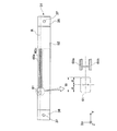
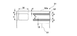
図4はカール押さえ部材31の保持部材52の要部を示す拡大図である。
保持部材52は、図4に示す予に該保持部材52の延在方向(Y方向)に沿って延び、各々が平行に配置された一対の直線部60a、60b(位置合わせマーク)と、直線部60a、60bの一端(第1カール押さえ取り付け部35)側に設けられた開口部61と、を有している。なお、センサー62は開口部61の中央部を通過する延長線上をX方向に沿って移動可能に設けられている。すなわち、開口部61は直線部60a,60bの中心線に対して対称となっている。この構成によれば、一対の直線部60a、60bを参照しつつ、開口部61内にロール紙Rの紙端を配置することでロール紙Rとの位置合わせ作業を容易に行うことができる。また、後述のように開口部61を介してロール紙Rの端部を検出することで、ロール紙Rに対する保持部材52の取付位置の確認を容易に行うことが可能となっている。また、保持部材52は開口部61以外の領域においてロール紙Rの側縁部を覆っているため、ロール紙Rの搬送時に該ロール紙Rが保持部材52に引っ掛る等の不具合を生じることがない。
FIG. 4 is an enlarged view showing a main part of the holding
The holding
本実施形態では、開口部61がロール紙Rの搬送方向上流側に形成されている。これにより、ロール紙Rの搬送方向上流側において保持部材52の取付位置を確認できるので、取付位置不良により保持部材によって良好に保持されていないロール紙Rが記録部20の下方に搬送されてしまうのを防止している。
In the present embodiment, the
図4に示すように、開口部61は略矩形状からなり四隅がR面取り加工されている。このように四隅をR面取り加工することで開口部61の角部から保持部材52に切り込みが入る等の不具合を防止し、保持部材52の強度を向上させている。また、開口部61の横方向(同図Y方向)における寸法をWとし、カール押さえ部材31等の組立公差を±αとした場合、W=2αの関係を満たすのが好ましい。このような寸法で開口部61を形成することで保持部材52の取付位置にバラツキが生じた場合でも位置検出部60が開口部61内のロール紙Rを確実に検出できるようになっている。また、開口部61の縦方向(同図X方向)における中央部の延長上は位置検出部60を構成する直線部60a、60bの中央部に一致するのが好ましい。このようにすれば、オペレーターがカール押さえ部材31の保持部材52とロール紙Rとを位置合わせする際、開口部61を目安として例えば一対の直線部60a、60bの間にロール紙Rの紙端を配置するようにロール紙Rに対する保持部材52の位置合わせ作業を行うことができる。なお、開口部61の中心にロール紙Rの端部が一致すると一対の直線部60a,60b間にロール紙Rの紙端が配置されることとなる。よって、オペレーターの保持部材52の位置決め時の作業性を向上させている。
As shown in FIG. 4, the
図5は本実施形態における保持部材52における開口部61及び直線部60a、60b等の寸法関係の一例を示す図である。図5に示すように、開口部61は保持部材52の端部から寸法Wが2mmに設定されており、上記横方向(同図Y方向)の寸法bが5mm、上記縦方向の(同図X方向)の寸法cが4.1mmとなっている。また、直線部60aは保持部材52の端部52aからの寸法dが1.5mmに設定され、その幅eは1.5mmに設定されている。また、直線部60bは直線部60aに対する間隔fが2.1mmに設定されており、直線部60aと同様、その幅eは1.5mmに設定されている。また、直線部60bから寸法gとして0.1mmだけ離間した位置にベース部51が配置されている。
FIG. 5 is a diagram illustrating an example of a dimensional relationship between the
次に、プリンター1が行う上記取付方法の確認方法について詳述する。この確認方法は、位置検出部60がロール紙Rの幅方向である−X方向に走査することでロール紙Rの幅方向におけるエッチ又は保持部材52の開口部61の幅方向(X方向)におけるエッチを検出する位置検出工程を含んでいる。
Next, a method for confirming the mounting method performed by the
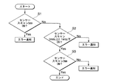
(位置検出工程)
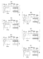
図6は位置検出工程を示すフローチャート図であり、図7は被記録媒体の端部と保持部材の位置関係を示す図である。
位置検出工程では検出部62がロール紙R及び開口部61の開口端を検出することでロール紙Rに対するカール押さえ部材31の取り付け位置が正しいか否かを検出することができる。位置検出工程は、第1のエッチを検出する第1の検出ステップS1と、第1のエッチを検出した場合において、第2のエッチを検出する第2の検出ステップと、第2のエッチを検出した場合において、第3のエッチを検出する第3の検出ステップと、を含む。
(Position detection process)
FIG. 6 is a flowchart showing the position detection process, and FIG. 7 is a view showing the positional relationship between the end of the recording medium and the holding member.
In the position detection step, the
プリンター1は、まず第1の検出ステップS1を開始する。
第1の検出ステップS1では、検出部62がロール紙Rの紙端の内側の所定位置(例えば、3mm内側の位置)から外側に向かって5mmだけ移動し、この間に第1のエッチを検出する。ここで、本実施形態に係るセンサー62は反射型センサーであるため、ロール紙R及び押さえ部材52と対向する場合にはロール紙R及び押さえ部材52の表面による反射光を受光する(以下、反射光を受光する場合を「センサーON状態」と称する)。一方、センサー62がロール紙Rの紙端或いは開口部61と対向する場合には反射光を受光しないこととなる(以下、反射光を受光しない場合を「センサーOFF状態」と称する)。
The
In the first detection step S1, the
ここで、保持部材52とロール紙Rの紙端との位置関係としては、第1として、図7(a)に示されるように保持部材52とロール紙Rの紙端とが平面視で重なっており、且つロール紙Rが開口部61を覆っている状態がある。また、第2として、図7(b)に示されるように保持部材52とロール紙Rの紙端とが平面視で重なっており、且つ保持部材52が端部52a及び開口部61の外側端部61a間に位置している状態がある。
また、第3として、図7(c)に示されるようにロール紙Rの紙端が開口部61内に位置するものの直線部60aに重なっている状態がある。また、第4として、図7(d)に示されるようにロール紙Rの紙端が開口部61内の所定の範囲(直線部60a、60bの間)に位置している状態がある。また、第5として、図7(e)に示されるようにロール紙Rの紙端が開口部61内に位置するものの直線部60bに重なっている状態がある。また、第6として、図7(f)に示されるようにロール紙Rの紙端と保持部材52とが重なっていない状態がある。
Here, as a positional relationship between the holding
Third, as shown in FIG. 7C, there is a state where the end of the roll paper R is positioned in the
図7(a)に示した状態では、センサー62が所定位置から5mm移動したとしても開口部61或いはロール紙Rの紙端を検出することができない。すなわち、センサー62は第1のエッチを検出することができない。この場合、センサー62はON状態のままとなる。したがって、プリンター1は、センサー62がON状態を検出した場合(YESの場合)、オペレーターに対してエラー信号を通知する。これにより、カール押さえ部材31がロール紙Rに対して所定の位置に取り付けられていないことをオペレーターに通知し、カール押さえ部材31の取付位置の調整を行わせることができる。
In the state shown in FIG. 7A, the
一方、センサー62がOFF状態を検出した場合(NOの場合)、プリンター1は第2の検出ステップS2を行う。第1の検出ステップS1においてセンサー62がOFF状態を検出した場合とは、センサー62が第1のエッチとしてロール紙Rの紙端(例えば、図7(d)、(f)の場合)或いは開口部61の開口端(例えば、図7(b)の場合)のいずれかを検出したことを意味する。この場合、図7(b)〜(f)の状態のいずれとなっている。
On the other hand, when the
第2の検出ステップS2では、センサー62がさらに3.1mmだけ移動し、第2のエッチとして開口部61の外側端部61a又は内側端部61bを検出する。ここで、図7(b)、(c)に示した状態では、センサー62が3.1mm移動したとしても開口部61の縦方向の寸法4.1mmを超えることがないので、開口部61の外側端部61aが検出されない。この場合、センサー62はOFF状態のままとなる。したがって、プリンター1は、センサー62がOFF状態のままである場合(NOの場合)、オペレーターに対してエラー信号を通知する。これにより、カール押さえ部材31がロール紙Rに対して所定の位置に取り付けられていないことをオペレーターに通知し、カール押さえ部材31の取付位置の調整を行わせることができる。
In the second detection step S2, the
また、図7(e)に示される状態では、センサー62は1.0mm移動するまでに開口部61の内側端部61bが検出され、ON状態を検出する。すなわち、センサー62が1.0mmよりも短い距離移動する間にON状態を検出した場合(NOの場合)、オペレーターに対してエラー信号を通知する。
In the state shown in FIG. 7E, the
また、図7(f)に示される状態においてロール紙Rと保持部材52とが3.1mmよりも長い距離離間していると、センサー62がOFF状態のままとなるので、オペレーターに対してエラー信号を通知する。これにより、図7(f)の状態を判別することができる。
Further, in the state shown in FIG. 7F, if the roll paper R and the holding
ところで、図7(e)に示される状態においてロール紙Rと保持部材52とが3.1mmよりも短い距離離間していると、第1の検出ステップS1においてセンサー62がロール紙Rの紙端によりOFF状態を検出し、第2の検出ステップS2においてセンサー62が保持部材52の端部52aによりON状態を検出する可能性がある。
By the way, if the roll paper R and the holding
そこで、本実施形態では第2の検出ステップS2においてセンサー62がON状態を検出した場合(YESの場合)、第3の検出ステップS3を行うようにしている。第3の検出ステップS3では、検出部62がさらに3.1mmだけ移動する。
Therefore, in this embodiment, when the
図7(d)に示されるようにロール紙Rの紙端が所定の範囲(直線部60a、60bの間)に位置している場合、センサー62が3.1mmだけ移動する間に開口部61の内側端部61bを検出し、ON状態(YESの場合)となる。なお、ロール紙Rの紙端が直線部60aの内側端部或いは直線部60bの内側端部に重なっている場合(同図中一点鎖線で示される場合)においては、センサー62が1.0mm以上3.1mm以下だけ移動する間に開口部61の内側端部61bを検出し、ON状態(YESの場合)となる。
As shown in FIG. 7D, when the end of the roll paper R is located within a predetermined range (between the
一方、図7(e)に示される状態においてロール紙Rと保持部材52とが1.0mmよりも短い場合、センサー62が3.1mmだけ移動する間に開口部61の外側端部61aを必ず検出し、ON状態(NOの場合)となる。このように第3の検出ステップS3により、図7(e)に示される状態においてロール紙Rと保持部材52とが1.0mmよりも短い場合を除外することができる。
On the other hand, if the roll paper R and the holding
このように第1の検出ステップS1乃至第3の検出ステップS3を経ることで、カール押さえ部材31がロール紙Rに対して所定の位置に取り付けられているかを検出することができる。したがって、オペレーターは上記位置検出工程に基づき、カール押さえ部材31を所定の位置に取り付けられることができる。
In this way, it is possible to detect whether the
以上述べたように、本実施形態に係るプリンター1によれば、カール押さえ部材31,32がロール紙Rを安定して保持するので、記録部20による記録動作を良好に行うことができる。
As described above, according to the
また、本実施形態に係るプリンター1によれば、保持部材52に形成した開口部61を介してセンサー62がロール紙Rの紙端を検出可能となっている。そのため、保持部材52におけるセンサー62の移動領域に対応する部分を切り欠く等の加工を行う必要が無いため、ロール紙Rが保持部材52の切欠部分に引っ掛かることで保持部材52が切れる等の不具合の発生を防止できる。
Further, according to the
以上、添付図面を参照しながら本発明に係る好適な実施形態について説明したが、本発明は係る例に限定されないことは言うまでもない。上述した例において示した各構成部材の諸形状や組み合わせ等は一例であって、本発明の主旨から逸脱しない範囲において設計要求等に基づき種々変更可能である。 As described above, the preferred embodiments according to the present invention have been described with reference to the accompanying drawings, but the present invention is not limited to the examples. Various shapes, combinations, and the like of the constituent members shown in the above-described examples are examples, and various modifications can be made based on design requirements and the like without departing from the gist of the present invention.
例えば、上記実施形態では、カール押さえ部材32を固定し、カール押さえ部材31のみを移動することで種々のロール紙Rに対応させる構成としたが、カール押さえ部材32が第1長穴部35a及び第2長穴部36aに沿って移動する構成であってもよい。この場合において、カール押さえ部材32についても位置検出部60を設けるようにしてもよい。
For example, in the above-described embodiment, the
また、上記実施形態では、加熱手段25が熱伝導式(接触式ともいう)の構成としたが、対流式でもよい。ここで、「熱伝導式」とは、物体の内部を通って高温部から低温部へ熱を伝える方式をいう。即ち、高温の物体がロール紙と接触することにより、ロール紙側へ熱を伝導する方式である。また、「対流式」とは、気体や液体などの流体によって熱を伝える方式をいう。 Moreover, in the said embodiment, although the heating means 25 was set as the heat conduction type (it is also called a contact type), a convection type may be sufficient. Here, the “heat conduction type” means a method of transferring heat from the high temperature part to the low temperature part through the inside of the object. That is, this is a system in which heat is conducted to the roll paper side when a high-temperature object comes into contact with the roll paper. The “convection type” refers to a method of transferring heat by a fluid such as gas or liquid.
1…インクジェットプリンター(記録装置)、24…プラテン(媒体支持部)、24a…支持面(媒体支持面)、31…カール押さえ部材(保持部材)、60…位置検出部(検出部)、60a,60b…直線部(位置合わせマーク)、61…開口部、R…ロール紙(被記録媒体)
DESCRIPTION OF
Claims (6)
前記被記録媒体の幅方向におけるエッチ又は前記保持部材に形成された前記被記録媒体に対する位置決め用の開口部の前記幅方向におけるエッチを検出する検出部が前記被記録媒体の幅方向に沿って前記保持部材側に走査する位置検出工程を有し、
前記位置検出工程は、第1のエッチを検出する第1の検出ステップと、前記第1のエッチを検出した場合において、第2のエッチを検出する第2の検出ステップと、前記第2のエッチを検出した場合において、第3のエッチを検出する第3の検出ステップと、を含むことを特徴とする保持部材の取付位置の確認方法。 A medium support unit that sucks and holds the back surface of the recording medium with the medium support surface; and a holding member that covers and holds the recording medium at a side edge in a direction substantially perpendicular to the conveyance direction of the recording medium. A method for confirming the mounting position of the holding member with respect to the recording medium in the recording apparatus,
A detection unit that detects an etch in the width direction of the recording medium or an etch in the width direction of an opening for positioning with respect to the recording medium formed on the holding member includes the detection unit along the width direction of the recording medium. A position detection step of scanning to the holding member side;
The position detection step includes a first detection step for detecting a first etch, a second detection step for detecting a second etch when the first etch is detected, and the second etch. And a third detection step of detecting a third etch, and a method for confirming the mounting position of the holding member.
前記被記録媒体の端部に対する位置合わせを行うための位置合わせマークと、
前記位置合わせマークに隣接して配置される開口部と、を有することを特徴とする保持部材。 Used in a recording apparatus having a medium support portion that sucks and holds the back surface of the recording medium with the medium support surface, and covers and holds the recording medium at a side edge in a direction substantially perpendicular to the transport direction of the recording medium. A holding member that
An alignment mark for alignment with the end of the recording medium;
And an opening disposed adjacent to the alignment mark.
前記被記録媒体の搬送方向と略直交する方向の側縁部において前記被記録媒体を覆って保持する請求項3〜5のいずれか一項に記載の保持部材と、
前記開口部を用いて前記被記録媒体の側縁部を検出し、前記保持部材との前記被記録媒体との位置関係を検出する検出部と、
を備えることを特徴とする記録装置。 A medium support unit for adsorbing and holding the back surface of the recording medium on the medium support surface;
The holding member according to any one of claims 3 to 5, which covers and holds the recording medium at a side edge portion in a direction substantially orthogonal to the conveyance direction of the recording medium;
Detecting a side edge portion of the recording medium using the opening, and detecting a positional relationship between the holding member and the recording medium;
A recording apparatus comprising:
Priority Applications (1)
| Application Number | Priority Date | Filing Date | Title |
|---|---|---|---|
| JP2010163656A JP5552935B2 (en) | 2010-07-21 | 2010-07-21 | Method for confirming mounting position of holding member and recording apparatus |
Applications Claiming Priority (1)
| Application Number | Priority Date | Filing Date | Title |
|---|---|---|---|
| JP2010163656A JP5552935B2 (en) | 2010-07-21 | 2010-07-21 | Method for confirming mounting position of holding member and recording apparatus |
Publications (2)
| Publication Number | Publication Date |
|---|---|
| JP2012024959A true JP2012024959A (en) | 2012-02-09 |
| JP5552935B2 JP5552935B2 (en) | 2014-07-16 |
Family
ID=45778507
Family Applications (1)
| Application Number | Title | Priority Date | Filing Date |
|---|---|---|---|
| JP2010163656A Expired - Fee Related JP5552935B2 (en) | 2010-07-21 | 2010-07-21 | Method for confirming mounting position of holding member and recording apparatus |
Country Status (1)
| Country | Link |
|---|---|
| JP (1) | JP5552935B2 (en) |
Cited By (3)
| Publication number | Priority date | Publication date | Assignee | Title |
|---|---|---|---|---|
| US20180093497A1 (en) * | 2016-10-04 | 2018-04-05 | Océ Holding B.V. | Method for processing a web in an apparatus |
| JP2018202743A (en) * | 2017-06-05 | 2018-12-27 | セイコーエプソン株式会社 | Printing device |
| JP2019038070A (en) * | 2017-08-25 | 2019-03-14 | ローランドディー.ジー.株式会社 | Cutting device |
Citations (8)
| Publication number | Priority date | Publication date | Assignee | Title |
|---|---|---|---|---|
| JPH01294078A (en) * | 1988-05-23 | 1989-11-28 | Seiko Epson Corp | Recording paper support device for printer |
| JPH0476792A (en) * | 1990-07-19 | 1992-03-11 | Ricoh Co Ltd | Handy scanner device and word area extraction device |
| JPH11208046A (en) * | 1998-01-29 | 1999-08-03 | Fuji Photo Film Co Ltd | Recording paper pressing mechanism of ink jet printer |
| JP2004230839A (en) * | 2003-01-31 | 2004-08-19 | Konica Minolta Holdings Inc | Recording paper holding mechanism of ink-jet printer |
| JP2004341280A (en) * | 2003-05-16 | 2004-12-02 | Dainippon Printing Co Ltd | Color filter manufacturing apparatus, color filter manufacturing method, and color filter |
| JP2008273002A (en) * | 2007-04-27 | 2008-11-13 | Canon Inc | Recording device |
| JP2010089875A (en) * | 2008-10-06 | 2010-04-22 | Murata Machinery Ltd | Paper tray unit |
| JP2010149317A (en) * | 2008-12-24 | 2010-07-08 | Seiko Epson Corp | Recording apparatus |
-
2010
- 2010-07-21 JP JP2010163656A patent/JP5552935B2/en not_active Expired - Fee Related
Patent Citations (8)
| Publication number | Priority date | Publication date | Assignee | Title |
|---|---|---|---|---|
| JPH01294078A (en) * | 1988-05-23 | 1989-11-28 | Seiko Epson Corp | Recording paper support device for printer |
| JPH0476792A (en) * | 1990-07-19 | 1992-03-11 | Ricoh Co Ltd | Handy scanner device and word area extraction device |
| JPH11208046A (en) * | 1998-01-29 | 1999-08-03 | Fuji Photo Film Co Ltd | Recording paper pressing mechanism of ink jet printer |
| JP2004230839A (en) * | 2003-01-31 | 2004-08-19 | Konica Minolta Holdings Inc | Recording paper holding mechanism of ink-jet printer |
| JP2004341280A (en) * | 2003-05-16 | 2004-12-02 | Dainippon Printing Co Ltd | Color filter manufacturing apparatus, color filter manufacturing method, and color filter |
| JP2008273002A (en) * | 2007-04-27 | 2008-11-13 | Canon Inc | Recording device |
| JP2010089875A (en) * | 2008-10-06 | 2010-04-22 | Murata Machinery Ltd | Paper tray unit |
| JP2010149317A (en) * | 2008-12-24 | 2010-07-08 | Seiko Epson Corp | Recording apparatus |
Cited By (5)
| Publication number | Priority date | Publication date | Assignee | Title |
|---|---|---|---|---|
| US20180093497A1 (en) * | 2016-10-04 | 2018-04-05 | Océ Holding B.V. | Method for processing a web in an apparatus |
| EP3305533A1 (en) * | 2016-10-04 | 2018-04-11 | OCE Holding B.V. | Method for processing a web in an apparatus |
| US10589546B2 (en) | 2016-10-04 | 2020-03-17 | Canon Production Printing Holding B.V. | Method for processing a web in an apparatus |
| JP2018202743A (en) * | 2017-06-05 | 2018-12-27 | セイコーエプソン株式会社 | Printing device |
| JP2019038070A (en) * | 2017-08-25 | 2019-03-14 | ローランドディー.ジー.株式会社 | Cutting device |
Also Published As
| Publication number | Publication date |
|---|---|
| JP5552935B2 (en) | 2014-07-16 |
Similar Documents
| Publication | Publication Date | Title |
|---|---|---|
| JP5720345B2 (en) | Recording device | |
| US8882372B2 (en) | Conveying device utilizing suction unit to attract print medium and printing apparatus using same | |
| CN101870199B (en) | recording device | |
| JP5451199B2 (en) | Recording device | |
| JP2004224505A (en) | Sheet separating device, sheet feeding device and image forming apparatus | |
| JP5311019B2 (en) | Recording device | |
| JP2008254218A (en) | Conveyance guide apparatus, recording apparatus, and liquid ejecting apparatus for recording material | |
| JP5552935B2 (en) | Method for confirming mounting position of holding member and recording apparatus | |
| JP6011209B2 (en) | Paper feeding device and image forming apparatus | |
| JP5304278B2 (en) | Inkjet recording device | |
| JP4764073B2 (en) | Sheet feeding apparatus and recording apparatus | |
| US9511607B2 (en) | Printhead protection device for direct-to-paper continuous-feed inkjet printer | |
| JP5488107B2 (en) | Recording apparatus and recording method | |
| JP7379890B2 (en) | Image forming device | |
| JP2006306616A (en) | Edge guide, recording apparatus, and liquid ejecting apparatus | |
| JP5751501B2 (en) | Recording device | |
| JP2009083350A (en) | Inkjet recording device | |
| JP5440317B2 (en) | Recording device | |
| JP2017193136A (en) | Inkjet printing apparatus and position adjustment method | |
| JP4692763B2 (en) | RECORDED MEDIUM SUPPORT DEVICE, RECORDING DEVICE, LIQUID EJECTING DEVICE | |
| KR100824119B1 (en) | Thermal recording device | |
| JP3774958B2 (en) | Inkjet recording device | |
| JP2017109364A (en) | Printing apparatus control method and printing apparatus | |
| JP4904845B2 (en) | Liquid ejecting apparatus and processing liquid mist collecting method | |
| JP6732462B2 (en) | Recording apparatus and method for controlling recording apparatus |
Legal Events
| Date | Code | Title | Description |
|---|---|---|---|
| A621 | Written request for application examination |
Free format text: JAPANESE INTERMEDIATE CODE: A621 Effective date: 20130403 |
|
| A131 | Notification of reasons for refusal |
Free format text: JAPANESE INTERMEDIATE CODE: A131 Effective date: 20140121 |
|
| A521 | Request for written amendment filed |
Free format text: JAPANESE INTERMEDIATE CODE: A523 Effective date: 20140303 |
|
| TRDD | Decision of grant or rejection written | ||
| A01 | Written decision to grant a patent or to grant a registration (utility model) |
Free format text: JAPANESE INTERMEDIATE CODE: A01 Effective date: 20140430 |
|
| A61 | First payment of annual fees (during grant procedure) |
Free format text: JAPANESE INTERMEDIATE CODE: A61 Effective date: 20140513 |
|
| R150 | Certificate of patent or registration of utility model |
Ref document number: 5552935 Country of ref document: JP Free format text: JAPANESE INTERMEDIATE CODE: R150 |
|
| S531 | Written request for registration of change of domicile |
Free format text: JAPANESE INTERMEDIATE CODE: R313531 |
|
| R350 | Written notification of registration of transfer |
Free format text: JAPANESE INTERMEDIATE CODE: R350 |
|
| LAPS | Cancellation because of no payment of annual fees |