JP2012024931A - Liquid storage container and liquid-jetting apparatus - Google Patents
Liquid storage container and liquid-jetting apparatus Download PDFInfo
- Publication number
- JP2012024931A JP2012024931A JP2010162539A JP2010162539A JP2012024931A JP 2012024931 A JP2012024931 A JP 2012024931A JP 2010162539 A JP2010162539 A JP 2010162539A JP 2010162539 A JP2010162539 A JP 2010162539A JP 2012024931 A JP2012024931 A JP 2012024931A
- Authority
- JP
- Japan
- Prior art keywords
- liquid
- stirring
- support
- container
- ink
- Prior art date
- Legal status (The legal status is an assumption and is not a legal conclusion. Google has not performed a legal analysis and makes no representation as to the accuracy of the status listed.)
- Granted
Links
- 239000007788 liquid Substances 0.000 title claims description 102
- 238000003860 storage Methods 0.000 title claims description 73
- 238000003756 stirring Methods 0.000 claims description 194
- 230000002265 prevention Effects 0.000 claims description 31
- 230000000149 penetrating effect Effects 0.000 claims description 7
- 210000000078 claw Anatomy 0.000 claims description 5
- 239000012530 fluid Substances 0.000 claims description 4
- 238000003780 insertion Methods 0.000 claims description 4
- 230000037431 insertion Effects 0.000 claims description 4
- 238000013019 agitation Methods 0.000 claims description 3
- 239000000976 ink Substances 0.000 description 148
- 239000000049 pigment Substances 0.000 description 18
- 238000004891 communication Methods 0.000 description 12
- 238000007639 printing Methods 0.000 description 10
- 238000012986 modification Methods 0.000 description 9
- 230000004048 modification Effects 0.000 description 9
- 239000000463 material Substances 0.000 description 8
- 238000004519 manufacturing process Methods 0.000 description 6
- 238000010586 diagram Methods 0.000 description 5
- 230000005484 gravity Effects 0.000 description 5
- 238000002347 injection Methods 0.000 description 5
- 239000007924 injection Substances 0.000 description 5
- 239000002612 dispersion medium Substances 0.000 description 4
- 238000012423 maintenance Methods 0.000 description 4
- 239000002184 metal Substances 0.000 description 3
- 238000004062 sedimentation Methods 0.000 description 3
- 230000001133 acceleration Effects 0.000 description 2
- 239000002585 base Substances 0.000 description 2
- 238000005452 bending Methods 0.000 description 2
- 238000009826 distribution Methods 0.000 description 2
- 239000011344 liquid material Substances 0.000 description 2
- 230000003287 optical effect Effects 0.000 description 2
- 238000001556 precipitation Methods 0.000 description 2
- 229920005989 resin Polymers 0.000 description 2
- 239000011347 resin Substances 0.000 description 2
- 238000007789 sealing Methods 0.000 description 2
- 239000002904 solvent Substances 0.000 description 2
- 239000000758 substrate Substances 0.000 description 2
- 238000000018 DNA microarray Methods 0.000 description 1
- 239000002253 acid Substances 0.000 description 1
- 239000003513 alkali Substances 0.000 description 1
- 238000004140 cleaning Methods 0.000 description 1
- 230000007547 defect Effects 0.000 description 1
- 238000007599 discharging Methods 0.000 description 1
- 238000001035 drying Methods 0.000 description 1
- 230000000694 effects Effects 0.000 description 1
- 239000007772 electrode material Substances 0.000 description 1
- 238000005401 electroluminescence Methods 0.000 description 1
- 238000005530 etching Methods 0.000 description 1
- 238000011049 filling Methods 0.000 description 1
- 239000004973 liquid crystal related substance Substances 0.000 description 1
- 230000007774 longterm Effects 0.000 description 1
- 239000000314 lubricant Substances 0.000 description 1
- 238000002844 melting Methods 0.000 description 1
- 230000008018 melting Effects 0.000 description 1
- 239000005416 organic matter Substances 0.000 description 1
- 230000010355 oscillation Effects 0.000 description 1
- 239000002245 particle Substances 0.000 description 1
- 230000035515 penetration Effects 0.000 description 1
- 230000002093 peripheral effect Effects 0.000 description 1
- 238000012545 processing Methods 0.000 description 1
- 238000009751 slip forming Methods 0.000 description 1
- 239000000243 solution Substances 0.000 description 1
- 239000000725 suspension Substances 0.000 description 1
- 229920003002 synthetic resin Polymers 0.000 description 1
- 239000000057 synthetic resin Substances 0.000 description 1
- XLYOFNOQVPJJNP-UHFFFAOYSA-N water Substances O XLYOFNOQVPJJNP-UHFFFAOYSA-N 0.000 description 1
- 238000003466 welding Methods 0.000 description 1
Images

Landscapes
- Ink Jet (AREA)
Abstract
Description
本発明は、液体収容容器及び液体噴射装置に関するものである。 The present invention relates to a liquid container and a liquid ejecting apparatus.
液体噴射ヘッドから液体を吐出する液体噴射装置として、インクジェット式プリンタがある。このプリンタは、カートリッジ又はインクタンクに貯留された染料インク又は顔料インクを記録ヘッドから吐出して印刷を行う。 As a liquid ejecting apparatus that ejects liquid from a liquid ejecting head, there is an ink jet printer. This printer performs printing by discharging dye ink or pigment ink stored in a cartridge or an ink tank from a recording head.
顔料インクは、耐ガス性、耐水性に優れるが、溶媒に色材を溶解した染料インクとは異なり、分散媒に顔料を分散させて製造されている。このため、長時間放置すると、顔料及び分散媒の比重差により顔料が沈降し、インクの濃度差が発生してしまう問題がある。 The pigment ink is excellent in gas resistance and water resistance, but is different from a dye ink in which a color material is dissolved in a solvent, and is manufactured by dispersing a pigment in a dispersion medium. For this reason, when left for a long time, there is a problem that the pigment settles due to the difference in specific gravity between the pigment and the dispersion medium, and the ink density difference occurs.
この問題に対し、顔料インクを撹拌する機構として、例えば、球状に形成された金属製の撹拌子を内部に配設し、キャリッジの動力に従ってこの撹拌子を転がせることでインクを撹拌するものがある。 To solve this problem, as a mechanism for stirring the pigment ink, for example, a metal stirrer formed in a spherical shape is disposed inside, and the stirrer is rolled according to the power of the carriage to stir the ink. is there.
さらに、インクカートリッジ内に、金属製の撹拌板を配設し、キャリッジの動力に従ってこの撹拌板を揺動させることでインクを撹拌するものが提案されている(特許文献1,2)。これら特許文献1,2には、インク収容室内に設けられた一対の支持部(軸受)によって撹拌部材が回動可能に支持された構成が記載されている。
Further, there has been proposed an ink cartridge in which a metal stirring plate is disposed and the stirring plate is rocked according to the power of the carriage to stir the ink (Patent Documents 1 and 2). These
しかしながら、上記文献の構成の場合、以下のような問題がある。
特許文献1には、軸部の先端に撹拌部材が抜け出すのを防止する抜け止め部を有する支持部が記載されているが、この抜け止め部は撹拌部材を軸部に取り付けた後、軸部の先端を熱加工で拡径することにより形成するか、あるいは抜け止め部を別部品として形成するかのいずれかにより形成される。このため、組み立て工数が多くなる。
特許文献2では、撹拌部材に軸受に軸支される回転軸が設けられており、その形状が複雑であるとともに、軸受や回転軸を別部品として形成するため、部品点数が多くなる。
However, the configuration of the above document has the following problems.
Patent Document 1 describes a support portion having a retaining portion that prevents the stirring member from slipping out at the tip of the shaft portion. This retaining portion is attached to the shaft portion after the stirring member is attached to the shaft portion. The tip is formed by expanding the diameter by thermal processing, or the retaining portion is formed as a separate part. For this reason, an assembly man-hour increases.
In
本発明は、上記従来技術の問題点に鑑み成されたものであって、組み立て工数の削減及び部品点数の削減を実現し得る構成とされた液体収容容器及び液体噴射装置を提供することを目的の一つとしている。 The present invention has been made in view of the above-described problems of the prior art, and an object thereof is to provide a liquid container and a liquid ejecting apparatus configured to realize a reduction in assembly man-hours and a reduction in the number of parts. One of them.
本発明の液体収容容器は、容器内に形成された貯留室に液体を収容する容器本体と、前記貯留室内に配設されて前記液体を撹拌する撹拌部材と、前記撹拌部材を移動可能に支持するとともに前記容器と一体的に形成された支持構造と、を備え、前記撹拌部材は、前記液体を撹拌する撹拌部と、前記撹拌部から延出する狭幅部および前記狭幅部の前記撹拌部とは反対側に設けられた係止部からなる装着部と、を有し、前記支持構造は、前記容器の壁部から前記貯留室内に突出し、前記係止部を挿通して支持する貫通部を形成する支持部を備えたことを特徴とする。 The liquid storage container of the present invention includes a container body that stores liquid in a storage chamber formed in the container, a stirring member that is disposed in the storage chamber and stirs the liquid, and supports the stirring member in a movable manner. And a stirring structure integrally formed with the container, and the stirring member includes a stirring unit that stirs the liquid, a narrow portion that extends from the stirring unit, and the stirring of the narrow portion A mounting portion comprising a locking portion provided on the opposite side of the portion, and the support structure protrudes from the wall portion of the container into the storage chamber and penetrates and supports the locking portion It has the support part which forms a part, It is characterized by the above-mentioned.
これによれば、液体を撹拌する撹拌部材を支持する支持構造は、容器と一体的に形成されていることから、容器に対して支持構造を別途形成したり、撹拌部材を組み込んだ後に先端を溶融させたりする必要がなくなるため、組み立て工数の削減および部品点数の削減を実現することができる。また、容器内において撹拌部材が支持部にて確実に支持されることとなり、液体の撹拌が良好に行えて顔料の沈降を防止することができる。 According to this, since the support structure that supports the stirring member that stirs the liquid is formed integrally with the container, the support structure is separately formed on the container, or the tip is attached after the stirring member is incorporated. Since it is not necessary to melt, it is possible to reduce the number of assembly steps and the number of parts. Further, the stirring member is reliably supported by the support portion in the container, so that the liquid can be satisfactorily stirred and the precipitation of the pigment can be prevented.
また、前記支持構造は前記支持部の外周と前記貫通部とを貫通する開口を有し、前記支持部が鉤形の一対の支持柱を対向させて構成されていてもよい。
これによれば、撹拌部材を、鉤形の一対の支持柱によって形成される開口を介して挿通部へと挿入させることにより、支持部に撹拌部材を支持させることができる。撹拌部材の取り付け作業が容易になる。
The support structure may have an opening that penetrates the outer periphery of the support portion and the penetration portion, and the support portion may be configured to face a pair of bowl-shaped support columns.
According to this, the stirring member can be supported by the support portion by inserting the stirring member into the insertion portion through the opening formed by the pair of bowl-shaped support pillars. The attaching work of the stirring member becomes easy.
また、前記装着部は、当該装着部と前記撹拌部とが並ぶ方向に直交する方向における前記狭幅部の幅が前記係止部の幅よりも小さく、前記貫通部の直径が、前記狭幅部の幅よりも広く、前記係止部の前記幅よりも狭くなるように形成されている構成としてもよい。
これによれば、一対の支持柱どうしの間に撹拌部材の狭幅部を挿通させて係止部を支持柱に支持させることにより、撹拌部材を支持柱間に垂下させた状態で支持させることが可能となる。これにより、撹拌部材が移動可能に支持されて、容器内の液体を効果的に撹拌することが可能となる。
In the mounting portion, the width of the narrow portion in a direction orthogonal to the direction in which the mounting portion and the stirring portion are arranged is smaller than the width of the locking portion, and the diameter of the through portion is the narrow width. It is good also as a structure formed so that it may be wider than the width | variety of a part and narrower than the said width | variety of the said latching | locking part.
According to this, the stirring member is supported in a suspended state between the support columns by inserting the narrow portion of the stirring member between the pair of support columns and supporting the locking portion on the support column. Is possible. Thereby, the stirring member is supported so as to be movable, and the liquid in the container can be effectively stirred.
また、前記一対の支持柱は、各々の先端に設けられた爪形状を呈する脱落防止部どうしの間隔が前記狭幅部の前記幅よりも狭くなるように配置されている構成としてもよい。
これによれば、支持部に支持された撹拌部材が支持柱に沿って移動(揺動、摺動)する際、撹拌部材の狭幅部が支持柱の脱落防止部に当接することによってそれ以上の移動が規制されるので、撹拌部材を支持部から脱落させることなく確実に支持することのできる支持構造となっている。
In addition, the pair of support columns may be arranged such that the interval between the drop-off preventing portions having a claw shape provided at the respective ends is narrower than the width of the narrow width portion.
According to this, when the stirring member supported by the support portion moves (swings and slides) along the support column, the narrow width portion of the stirring member abuts against the drop-off prevention portion of the support column. Therefore, the support structure can be surely supported without dropping the stirring member from the support portion.
また、前記一対の支持柱には、先端に向かって隣り合う他の前記支持柱との距離が広がるように傾斜する傾斜面が形成されている構成としてもよい。
これによれば、支持部に撹拌部材を支持させる際、各支持柱に形成された傾斜面によって開口側から貫通部内へと撹拌部材が誘導され、撹拌部材を支持部に組み込むことが容易になる。
Moreover, it is good also as a structure by which the inclined surface which inclines so that the distance with the said other support pillar adjacent to the front-end | tip may spread may be formed in a pair of said support pillar.
According to this, when the stirring member is supported by the support portion, the stirring member is guided from the opening side into the through portion by the inclined surface formed on each support column, and the stirring member can be easily incorporated into the support portion. .
また、前記撹拌部の一辺に沿って複数の前記装着部が一列に並んで設けられており、前記支持部が前記装着部の数に応じて複数設けられている構成としてもよい。
これによれば、撹拌部材の大きさに係わらず、支持部において撹拌部材を安定して支持させることが可能となる。これにより、液体の撹拌効率が向上し、顔料の沈降を効果的に防止することができる。
Moreover, it is good also as a structure by which the said some mounting part is provided in a line along one side of the said stirring part, and the said support part is provided with two or more according to the number of the said mounting parts.
According to this, regardless of the size of the stirring member, it is possible to stably support the stirring member in the support portion. Thereby, the stirring efficiency of a liquid improves and sedimentation of a pigment can be prevented effectively.
本発明の液体収容容器は、容器内に形成された貯留室に液体を収容する容器本体と、前記貯留室内に配設されて前記液体を撹拌する撹拌部材と、前記撹拌部材を移動可能に支持するとともに前記容器と一体的に形成された支持構造と、を備え、前記支持構造は、前記容器の壁面から前記貯留室内に突出する軸体と、当該軸体の先端に設けられ前記軸体の径方向に移動可能な複数の脱落防止部と、を有する支持部を有し、前記撹拌部材は、前記液体を撹拌するとともに前記脱落防止部を挿通可能な係止孔を有する撹拌部を有することを特徴とする。 The liquid storage container of the present invention includes a container body that stores liquid in a storage chamber formed in the container, a stirring member that is disposed in the storage chamber and stirs the liquid, and supports the stirring member in a movable manner. And a support structure integrally formed with the container, the support structure including a shaft body projecting from the wall surface of the container into the storage chamber, and a shaft body provided at a tip of the shaft body. A support portion having a plurality of dropout prevention portions movable in the radial direction, and the stirring member has a stirring portion having a locking hole for stirring the liquid and allowing the dropout prevention portion to be inserted therethrough. It is characterized by.
これによれば、液体を撹拌する撹拌部材を支持する支持構造は、容器と一体的に形成されていることから、容器に対して支持構造を別途形成したり、撹拌部材を組み込んだ後に先端を溶融させたりする必要がなくなるため、組立て工数の削減および部品点数の削減を実現することができる。また、容器内において撹拌部材が支持部にて確実に支持されることとなり、液体の撹拌が良好に行えて顔料の沈降を防止することができる。 According to this, since the support structure that supports the stirring member that stirs the liquid is formed integrally with the container, the support structure is separately formed on the container, or the tip is attached after the stirring member is incorporated. Since there is no need to melt, it is possible to reduce the number of assembling steps and the number of parts. Further, the stirring member is reliably supported by the support portion in the container, so that the liquid can be satisfactorily stirred and the precipitation of the pigment can be prevented.
また、前記撹拌部の一辺に沿って複数の前記係止孔が一列に並んで設けられており、前記支持部が前記係止孔の数に応じて複数設けられている構成としてもよい。
これによれば、撹拌部材の大きさに係わらず、支持部において撹拌部材を安定して支持させることが可能となる。これにより、液体の撹拌効率が向上し、顔料の沈降を効果的に防止することができる。
Further, a plurality of the locking holes may be provided in a line along one side of the stirring portion, and a plurality of the supporting portions may be provided according to the number of the locking holes.
According to this, regardless of the size of the stirring member, it is possible to stably support the stirring member in the support portion. Thereby, the stirring efficiency of a liquid improves and sedimentation of a pigment can be prevented effectively.
また、前記容器と一体的に形成されたピンを有し、前記撹拌部材には前記ピンを挿入可能な挿入孔が形成されている構成としてもよい。
これによれば、支持部に支持される撹拌部材の意図しない方向への回転を規制することができるので、液体の撹拌効率が向上する。
Moreover, it is good also as a structure which has the pin integrally formed with the said container and the said agitation member is formed with the insertion hole which can insert the said pin.
According to this, since the rotation of the stirring member supported by the support portion in the unintended direction can be restricted, the liquid stirring efficiency is improved.
本発明の液体噴射装置は、主走査方向に沿って往復移動するキャリッジに液体収容容器及び液体噴射ヘッドを搭載し、前記液体収容容器から前記液体噴射ヘッドに液体を供給する液体噴射装置において、上記前記液体収容容器を用いることを特徴とする。
これによれば、長時間使用しない期間があったとしても、液体中の顔料の沈降を防止して容器内における液体の濃度差を無くすことができる。これにより、液体噴射ヘッドに良好な状態の液体を常に供給することが可能となり、記録品質の低下を招くことを阻止することができる。
The liquid ejecting apparatus according to the aspect of the invention includes the liquid container and the liquid ejecting head mounted on a carriage that reciprocates along the main scanning direction, and the liquid ejecting apparatus that supplies the liquid from the liquid container to the liquid ejecting head. The liquid container is used.
According to this, even if there is a period of not using for a long time, sedimentation of the pigment in the liquid can be prevented and the difference in the concentration of the liquid in the container can be eliminated. Accordingly, it is possible to always supply a liquid in a good state to the liquid ejecting head, and it is possible to prevent a decrease in recording quality.
また、前記液体収容容器は、前記撹拌部材が前記主走査方向に移動可能に配設される構成としてもよい。
これによれば、キャリッジの主走査方向への移動にしたがって撹拌部材が移動することになり、記録中のみならず、非記録中にキャリッジを移動させることで非記録中においても液体の撹拌が可能となる。
The liquid container may have a configuration in which the stirring member is arranged to be movable in the main scanning direction.
According to this, the stirring member moves as the carriage moves in the main scanning direction, and the liquid can be stirred not only during recording but also during non-recording by moving the carriage during non-recording. It becomes.
以下、本発明の実施形態につき、図面を参照して説明する。なお、以下の説明に用いる各図面では、各部材を認識可能な大きさとするため、各部材の縮尺を適宜変更している。
以下、本発明の実施形態について図面を参照して説明する。
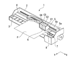
図1は、本実施形態に係るインクジェット式記録装置(以下、単にプリンタ1という)の要部を説明する斜視図である。
Embodiments of the present invention will be described below with reference to the drawings. In each drawing used for the following description, the scale of each member is appropriately changed to make each member a recognizable size.
Embodiments of the present invention will be described below with reference to the drawings.
FIG. 1 is a perspective view illustrating a main part of an ink jet recording apparatus (hereinafter simply referred to as a printer 1) according to the present embodiment.
図1に示すように、プリンタ(液体噴射装置)1は、上側が開口する略直方体形状のフレーム2を備えている。フレーム2には、プラテン3が架設されており、不図示の紙送り機構により、このプラテン3上を印刷用紙Pが副走査方向(図1中Y軸方向)に給送されるようになっている。
そして、フレーム2にはプラテン3と平行にガイド部材4が架設されており、このガイド部材4には、キャリッジ5がガイド部材4の軸線方向に移動可能に挿通支持されている。
また、このキャリッジ5は、タイミングベルト5bを介してキャリッジモータ5aに駆動連結されており、キャリッジモータ5aの駆動によってガイド部材4に沿って主走査方向(図1中X軸方向)に往復移動されるようになっている。
As shown in FIG. 1, a printer (liquid ejecting apparatus) 1 includes a substantially
A
The carriage 5 is drivingly connected to a
また、キャリッジ5には、4つのインクカートリッジ(液体収容容器)Cが着脱可能に装着されている。具体的には、第1インクカートリッジC1〜第4インクカートリッジC4が着脱可能に装着されている。
第1インクカートリッジC1は、内部に、ブラックインクを収容している。第2インクカートリッジC2〜第4インクカートリッジC4は、内部に、各種カラーインクを収容している。各種インクは、例えば、分散媒に色材である顔料を分散させた、いわゆる顔料インクである。
なお、第1インクカートリッジC1〜第4インクカートリッジC4を互いに区別しないで説明する場合には、単にインクカートリッジCとして説明する。また、ブラックインク及び各種カラーインクを総称して、インクとして説明する。
In addition, four ink cartridges (liquid storage containers) C are detachably mounted on the carriage 5. Specifically, the first ink cartridge C1 to the fourth ink cartridge C4 are detachably mounted.
The first ink cartridge C1 contains black ink inside. The second ink cartridge C2 to the fourth ink cartridge C4 contain various color inks therein. The various inks are, for example, so-called pigment inks in which a pigment that is a color material is dispersed in a dispersion medium.
When the first ink cartridge C1 to the fourth ink cartridge C4 are described without being distinguished from each other, they are simply referred to as the ink cartridge C. Further, black ink and various color inks are collectively referred to as ink.
キャリッジ5のプラテン3に対向する面には、記録ヘッド(液体噴射ヘッド)6が搭載されている。記録ヘッド6の下面には不図示のノズル列の開口が形成されている。
各ノズル列は、各インクにそれぞれ対応しており、不図示の圧電素子の駆動により、印刷用紙P上にインクの液滴が吐出されるようになっている。
A recording head (liquid ejecting head) 6 is mounted on the surface of the carriage 5 facing the
Each nozzle row corresponds to each ink, and ink droplets are ejected onto the printing paper P by driving a piezoelectric element (not shown).
また、フレーム2内には、メンテナンスユニット7が備えられている。メンテナンスユニット7は、キャリッジ5の移動範囲内であって、印刷用紙Pの搬送経路外の領域である非印刷領域に設けられており、本実施形態では図1中右側に設けられたホームポジションに配設されている。
このメンテナンスユニット7は、非印刷状態のときに記録ヘッド6をキャップ8にて封止し、ノズル内の乾燥や印刷不良を防止するためのヘッドクリーニングを行うものである。
A
This
(インクカートリッジの第1実施形態)
次に、第1実施形態に係るインクカートリッジについて、図2〜図5を参照して説明する。
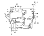
図2は、第1実施形態に係るインクカートリッジの概略構成を示す斜視図である。
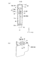
図3は、インクカートリッジの詳細な構成を示す側面図である。
(First embodiment of ink cartridge)
Next, the ink cartridge according to the first embodiment will be described with reference to FIGS.
FIG. 2 is a perspective view illustrating a schematic configuration of the ink cartridge according to the first embodiment.
FIG. 3 is a side view showing a detailed configuration of the ink cartridge.
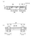
図2及び図3に示すように、インクカートリッジC1〜C4は、略直方体状に形成されたケース10(容器)を備えている。ケース10は、一側面(右壁部)が開口した箱体状に形成されたケース本体(容器本体)11と、右壁部となるフィルム状の蓋部12とから構成されている。
ケース10は、具体的には、上壁部11a、底壁部11b、前壁部11c、背壁部11d及び左壁部11eにより、右壁部側が開口した箱体状に形成されている。
As shown in FIGS. 2 and 3, the ink cartridges C1 to C4 include a case 10 (container) formed in a substantially rectangular parallelepiped shape. The
Specifically, the
そして、ケース本体11の内部には、ケース本体11の開口を蓋部12により封止することにより形成されたインクを貯留可能な第1インク貯留室13A及び第2インク貯留室13Bが設けられている。具体的には、上壁部11a、底壁部11b、前壁部11c及び背壁部11dの右壁部側の側面にフィルム状の蓋部12を溶着することで、密閉された第1インク貯留室13A及び第2インク貯留室13Bが形成されている。
The case
ケース本体11の上壁部11aには、インク注入孔14が貫通形成されている。このインク注入孔14からは、インクが第1インク貯留室13A内に注入されるようになっている。
また、上壁部11aには、大気連通孔15a及び連通溝15bが形成されている。大気連通孔15aは、上壁部11aに貫通形成され、第1インク貯留室13Aと外部とを連通している。連通溝15bは、上壁部11aを蛇行するように形成され、大気連通孔15aに連通している。
また、インク注入孔14、大気連通孔15a及び連通溝15bの一部は、上壁部11aに貼着された封止フィルム16によって封止される。
そして、第1インク貯留室13A内は、封止された大気連通孔15a及び連通溝15bを介して、大気開放された連通溝15bの端部によって、大気に開放される。
An
The
In addition, a part of the
The inside of the first
また、ケース本体11の底壁部11bには、インク吐出孔17が貫通形成されている。このインク吐出孔17は、底壁部11bの外側面に突出形成された供給部18内に連続して形成され、供給部18の下面にて開口している。
供給部18内には、不図示の弁機構が備えられ、インクカートリッジC1〜C4をキャリッジ5に装着すると、キャリッジ5に設けられた不図示のインク針が供給部18内に貫挿されて弁機構を開弁し、第2インク貯留室13B内のインクをインク針に供給するようになっている。
An
A valve mechanism (not shown) is provided in the
ケース本体11は、このケース本体11と一体的に形成された複数の支持柱(支持部)21を有し、左壁部11eから第1インク貯留室13A及び第2インク貯留室13B内に向けて立設するように形成されている。支持柱21は第1インク貯留室13A及び第2インク貯留室13B内にそれぞれ2本ずつ形成され、これら2本の支持柱21,21が奥行き方向(Y軸方向)に所定の間隔を空けて並んで設けられている。
The case
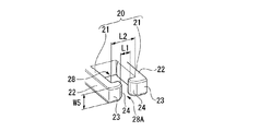
図3に示すように、第1インク貯留室13A及び第2インク貯留室13B内には、それぞれインク(液体:図6)Kを撹拌する撹拌板25(25A,25B:撹拌部材)が設けられており、それぞれが支持部20によって移動可能に支持されている。
As shown in FIG. 3, stirring plates 25 (25A, 25B: stirring members) for stirring ink (liquid: FIG. 6) K are provided in the first
本実施形態の支持部20は、ケース本体11の左壁部(壁面)11eから貯留室13A,13B内に突出しており、撹拌板25A,25Bを挿通して支持する貫通部28(図6)と、外周と貫通部28とを貫通する開口28A(図6)とを有して構成されている。
The
具体的に、支持部20は、ケース本体11の左壁部(壁面)11eから貯留室13A,13B内に突出する2本の支持柱(支持軸)21,21によって構成されている。これら2本の支持柱21,21は、鉤形を呈するもので、上記した貫通部28および開口28Aを形成すべく、互いに所定の間隔をおいて配置されている。これら2本の支持柱21,21に、ケース本体11の幅方向(X方向)へ揺動、摺動可能に引っ掛けられるように係合している。このような支持部20によって本実施形態の支持構造が構成されている。
Specifically, the
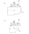
図4(a)は、第1インク貯留部内に装着される撹拌板の概略構成を示す平面図、図4(b)は、第2インク貯留部内に装着される撹拌板の概略構成を示す平面図である。
撹拌板25A,25Bは、インクの比重より大きい比重を有する合成樹脂又は金属等からなる平面視略矩形状の平板であって、インクを撹拌する撹拌部26と支持柱21,21に装着される装着部27とをそれぞれ有して構成されている。装着部27は、撹拌部26の面方向外側に延出する第1部位(狭幅部)27Aと、第1部位27Aの撹拌部26側とは反対側に設けられた第2部位(係止部)27Bと、を有する。そして、これら撹拌部26と装着部27との間には鉤形の切欠部25a,25aが形成されている。
FIG. 4A is a plan view showing a schematic configuration of the stirring plate mounted in the first ink reservoir, and FIG. 4B is a plan view showing a schematic configuration of the stirring plate mounted in the second ink reservoir. FIG.
The stirring
撹拌板25A,25Bは、撹拌部26と装着部27とが面方向で並ぶ方向(垂直方向)に直交する方向(水平方向)において、撹拌部26の幅W1(最大幅)と、第1部位27Aの幅W2と、第2部位27Bの幅W3とは、幅W2<幅W3<幅W1となるような寸法に設定されている。また、垂直方向における切欠部25a,25aの幅W4(撹拌部26と第2部位27Bとの間隔)は、支持柱21の幅W5(図6)よりも大きい。
撹拌板25A,25Bの形状は貯留室13A,13Bの形状沿って形成されており、これら貯留室13A,13Bの形状に応じて適宜変更が可能である。本実施形態における撹拌板25A,25Bの厚みは約1mmとするが、撹拌部26の大きさや貯留室13A,13Bの大きさ、インクの粘性などに応じて適宜変更が可能である。
The
The shapes of the stirring
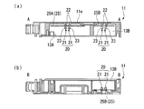
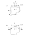
図5(a)は、図3のA−A線に沿う断面図であり、図5(b)は、図3のB−B線に沿う断面図である。また、図6は、インクカートリッジの支持構造を拡大して示す斜視図である。図7(a)は、インクカートリッジ内での撹拌板の移動状態を示す断面図、図7(b)はインクカートリッジ内での撹拌板の支持状態を示す斜視図である。 5A is a cross-sectional view taken along line AA in FIG. 3, and FIG. 5B is a cross-sectional view taken along line BB in FIG. FIG. 6 is an enlarged perspective view showing the ink cartridge support structure. FIG. 7A is a cross-sectional view showing a moving state of the stirring plate in the ink cartridge, and FIG. 7B is a perspective view showing a supporting state of the stirring plate in the ink cartridge.
図5(a),(b)に示すように、各貯留室13A,13B内にそれぞれ形成される支持部20,20、つまり各支持部20を構成する一対の支持柱21,21はケース本体11と一体的に形成されている。支持柱21は、ケース本体11の左壁部11eから垂直に突出するとともに撹拌板25A,25Bを支持する支持軸22と、支持軸22の先端に設けられ支持軸22の外周面よりも外側に突出する爪形状を呈した脱落防止部23と、を有して鉤形を呈するように構成されている。この脱落防止部23は支持軸22よりも対向する支持柱21側へと突出しており、対向する支持柱21,21における脱落防止部23,23どうしの間に形成される開口28Aが、対向する支持軸22,22どうしの間に形成される貫通部28と外側との連通口となっている。これら支持柱21,21の脱落防止部23,23によって、各支持部20から撹拌板25(25A,25B)が外れることが防止されている。
As shown in FIGS. 5 (a) and 5 (b), the
次に、支持部20の構成について詳述する。
図6に示すように、上記第1インク貯留室13Aおよび第2インク貯留室13B内にそれぞれ配置される一対の支持柱21,21は、互いの脱落防止部23,23を対向させた状態でこれらが向き合う方向に所定の間隔を置いて配置されている。これら一対の支持柱21は、対向する脱落防止部23,23どうしの間の間隔L1が、撹拌板25A,25Bにおける装着部27の第1部位27Aの幅W2(図4(a),(b))よりも狭く(L1<W2)なるように配置されている。また、支持軸22,22どうしの間の間隔L2が装着部27の第1部位27Aの幅W2よりも広く、かつ、第2部位27Bの幅W3よりも狭い間隔となるように配置されている。
Next, the structure of the
As shown in FIG. 6, the pair of
支持柱21,21には、脱落防止部23,23の先端側に隣り合う他の支持柱21との距離が広がるように傾斜する傾斜面24が形成されている。支持柱21,21にそれぞれ形成された傾斜面24,24により、撹拌板25(25A,25B)が開口28Aから貫通部28(支持軸22,22)側へと誘導されやすくなる。
このような一対の支持柱21,21間に撹拌板25(25A,25B)の装着部27(第1部位27A)がはめ込まれるようにして装着されている。
The
The mounting portion 27 (
支持柱21,21間に撹拌板25(25A,25B)をはめ込む際、支持柱21,21の先端側に装着部27を押し付けて、開口28Aから貫通部28へと挿入させる。つまり、押し付けられた第1部位27Aによって支持柱21,21が左右に押し退けられて、脱落防止部23,23どうしが互いに離間する方向へ撓むことで、撹拌板25(25A,25B)が支持軸22,22間の貫通部28に挿入されるようになっている。
When the stirring plate 25 (25A, 25B) is fitted between the
本実施形態においては、上述したように、支持柱21,21の先端側にそれぞれ傾斜面24が設けられた構成のため、撹拌板25(25A,25B)の第1部位27Aを傾斜面24,24に沿って押し込むことで支持柱21,21どうしが離間する方向へ撓んで支持軸22,22側へと撹拌板25(25A,25B)がスムーズに移動する(誘導される)ことになる。
In the present embodiment, as described above, since the
これにより、撹拌板25(25A,25B)は、各々の重力によって鉛直方向に垂下した状態で2本の支持柱21,21に支持される。上記した支持柱21,21の配置間隔及び撹拌板25(25A,25B)の形状により、撹拌板25(25A,25B)が支持柱21,21に支持された状態において、装着部27の第1部位27Aの両側部が同時に支持軸22,22に接触することはなく、支持軸22,22に対して移動可能に支持されることになる。このため、撹拌板25(25A,25B)は、インクカートリッジCの幅方向(X方向:図7(a))に揺動したり、摺動したりできるように、2本の支持柱21,21に支持される。図7(b)に示すように、撹拌板25(25A,25B)は支持軸22,22に沿って移動し、脱落防止部23,23に当接することでそれ以上の移動は規制され、支持柱21,21からの脱落が防止されている。
Thereby, the stirring plate 25 (25A, 25B) is supported by the two
したがって、インクカートリッジCに外力が加えられ、インクカートリッジCがX軸方向と平行な方向に、所定の加速度又は減速度以上で加速又は減速されると、撹拌板25に対して加わった慣性力及び重力の合力がインクから受ける圧力等を上回り、撹拌板25(25A,25B)が、幅方向(X方向)に揺動(振子運動)したり、摺動(平行移動)したりするようになっている。
Accordingly, when an external force is applied to the ink cartridge C and the ink cartridge C is accelerated or decelerated in a direction parallel to the X-axis direction at a predetermined acceleration or deceleration or more, the inertial force applied to the stirring
従来においては、撹拌板25が2本の支持柱21,21から脱落しないように(外れないように)、支持柱21,21間に撹拌板25を配置した後に支持柱21,21の先端部分を溶融変形させることにより拡径させていたため、製造に手間と時間がかかる。また、ケース本体11に対して支持柱21,21が別部品として設けられていることも多く、この場合には製造工程数が多くなるという問題があった。
In the related art, after the stirring
本実施形態におけるインクカートリッジCは、撹拌板25(25A,25B)をそれぞれ支持する一対の支持柱21,21がケース本体11と一体的に形成されている。そして、これら支持柱21,21間に撹拌板25(25A,25B)を嵌め込むことで組み込むことのできる構成であることから、製造も簡単で作業工数も少なくなる。
よって、本実施形態の構成および製造方法によれば、組み立て工数の削減及び部品点数の削減を実現できる。
In the ink cartridge C in the present embodiment, a pair of
Therefore, according to the configuration and the manufacturing method of the present embodiment, it is possible to reduce the number of assembly steps and the number of parts.
次に、インクカートリッジCの作用について説明する。
各インクカートリッジCには、インク注入孔14から、インクが予め決められた初期充填量だけ注入される。
Next, the operation of the ink cartridge C will be described.
Ink is injected into each ink cartridge C from the
そして、キャリッジ5にインクカートリッジCを装着すると、図1に示すように、インクカートリッジCの幅方向が、キャリッジ5の主走査方向(X軸方向)と平行になるように配設される。つまり、第1インク貯留室13A,第2インク貯留室13B内の撹拌板25A,25Bが移動可能な方向とキャリッジ5の主走査方向が一致するように配設される。
When the ink cartridge C is mounted on the carriage 5, the width direction of the ink cartridge C is disposed so as to be parallel to the main scanning direction (X-axis direction) of the carriage 5 as shown in FIG. That is, the
次に、インクの撹拌又は印刷を行う目的で、キャリッジ5を主走査方向に沿って加速又は減速すると、インクカートリッジC内に設けられた撹拌板25A,25Bは、キャリッジ5の移動動作に従って移動し始める。これら撹拌板25A,25Bにより、第1インク貯留室13A,第2インク貯留室13B内のインクを効率的に撹拌することができる。
Next, when the carriage 5 is accelerated or decelerated along the main scanning direction for the purpose of stirring or printing ink, the stirring
その結果、第1インク貯留室13A,第2インク貯留室13B内のインクが均等に撹拌され、顔料の濃度分布も均一になる。また、撹拌板25A,25Bが垂下するように設けられたことで、小さな外力で容易に移動し、しかも何度も往復移動する。
As a result, the ink in the first
そして、第1インク貯留室13A,第2インク貯留室13B内のインクは、顔料濃度分布が偏りのない状態となり、顔料濃度が均一なインクが供給部18を介して記録ヘッド6に供給される。このため、例えば、比較的長い印刷休止期間の後に印刷を行っても、色濃度の偏りのない印刷物が作成される。
The ink in the first
また、インクカートリッジCに対して加える外力は、キャリッジ5の主走査方向の移動伴う加減速による慣性力には限らない。インクカートリッジCを長期保管等する場合に、各インクカートリッジCを幅方向等に振ることで、第1インク貯留室13A,第2インク貯留室13B内の撹拌板25A,25Bがそれぞれ移動して、インクが撹拌される。長期保管により、第1インク貯留室13A,第2インク貯留室13Bの底部には、インクに含有される顔料が沈降している場合であっても、撹拌板25,25Bの下端が第1インク貯留室13A,第2インク貯留室13Bの底部に近接しているので、沈降している顔料なども確実に浮遊して撹拌される。
Further, the external force applied to the ink cartridge C is not limited to the inertial force due to acceleration / deceleration accompanying the movement of the carriage 5 in the main scanning direction. When the ink cartridge C is stored for a long time, the stirring
このように、本実施形態の構成によれば、撹拌板25(25,25B)を移動可能に支持する支持部20がケース本体11と一体的に形成されていることから、ケース本体11に対して支持部20を別途形成することもなくなり、組み立て工数の削減を実現することができる。
Thus, according to the structure of this embodiment, since the
また、支持柱21,21の爪形状をなす脱落防止部23,23に撹拌板25の装着部27(切欠部25a)が係合することによって、支持軸22,22から撹拌板25が脱落することが防止され、支持部20によって撹拌板25が確実に支持されるようになっている。また、支持部20を構成する一対の支持柱21,21は、対向する脱落防止部23,23どうしの間隔L1が撹拌板25の第1部位27Aの幅W2よりも狭くなるように配置されていることから、一旦、支持部20に装着された撹拌板25は、脱落防止部23,23どうしの間隔を広げる外力がかからない限り一対の支持柱21,21から取り外すことが困難になる。このため、ケース本体11が倒れるなどした場合にも支持部20から撹拌板25が外れてしまうことが防止され、支持部20に対して撹拌板25が確実に支持されるようになっている。
In addition, the
また、一対の支持柱21,21には、それぞれ、脱落防止部23の先端側にかけて隣り合う他の支持柱21との距離を広げるように傾斜する傾斜面24が形成されている。このため、撹拌板25を支持部20の支持柱21,21間に装着させる際に、傾斜面24によって撹拌板25が支持柱21,21の支持軸22,22間に誘導されるので装着しやすい。
Each of the pair of
(変形例)
図8(a)は、撹拌板25A(25B)の回転状態を説明するための図、図8(b)は、撹拌板および支持構造の変形例を示す図である。
なお、本実施形態の撹拌板25A,25Bは、上端側の中央部分に設けられた1つの装着部27によって各インク貯留室13A,13B内に保持されるため、撹拌時に装着部27を支点として面方向(図8(a)中の矢印で示す方向)へ回転してしまうおそれがある。
(Modification)
FIG. 8A is a view for explaining the rotation state of the stirring
The stirring
そこで、例えば、図8(b)に示すように、撹拌板25A,25Bそれぞれの撹拌部26の幅方向両側付近に長孔(挿入孔)26a,26aを形成するとともに、これら長孔26a,26aと対向するケース本体11の所定の位置にピン19,19を形成しておき、長孔26a,26a内にピン19,19を挿入させることにより、撹拌板25A,25Bの意図しない方向への回転を防止する構成にしても良い。
Therefore, for example, as shown in FIG. 8B, long holes (insertion holes) 26a, 26a are formed in the vicinity of both sides in the width direction of the stirring
長孔26a,26aは、長軸が撹拌部26の上下方向に沿う楕円形状を呈している。長軸の長さは、例えば、撹拌板25A,25Bがそれぞれ支持柱21,21上の所定の位置において装着部27を支点として揺動する際に、装着部27とは反対側の下端側が移動する量に応じて設定される。つまり、撹拌板25A,25Bの揺動(範囲)の妨げにならない大きさで形成されている。一方、長孔26a,26aの短軸は、ピン19の直径よりも若干長さを有する程度に設定される。そして、取り付ける際、長孔26a,26a内にピン19,19を同時にはめ込む。
The
これにより、撹拌板25A,25Bの面方向への回転が防止されて撹拌板25A,25Bの移動方向(撹拌方向)を所望の方向へ規制することができるとともに、撹拌板25A,25Bの支持状態が安定するので、インクの撹拌効果が高められる。また、これら長孔26aおよびピン19によって、装着時における支持部20への撹拌板25A,25Bの位置決めを行うことができ、組み立てが容易になる。
Thereby, rotation to the surface direction of stirring
なお、本実施形態では、支持部20に対して撹拌板25を装着させる際、支持柱21,21が互いに離間する方向へ撓むことによって撹拌板25が支持柱21,21間に挿入されるようになっているが、撹拌板25を可撓性材料より構成しておき、撹拌板25側が変形することによって支持柱21,21間に挿入されるようになっていてもよい。
In this embodiment, when the agitating
また、撹拌板25がこれを支持する支持部20よりも可撓性を有する材料によって形成されていてもよい。この場合、撹拌板25を支持部20に取り付ける際、撹拌板25側を変形させながら支持柱21,21間へはめ込むことが可能となる。
Moreover, the stirring
(インクカートリッジの第2実施形態)
次に、第2実施形態のインクカートリッジCについて説明する。
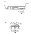
図9は、第2実施形態のインクカートリッジCの概略構成を示す側面図である。
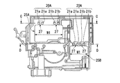
図10(a)は、図9のC−C断面図、図10(b)は(a)に示す支持機構の拡大図であり、図11(a)は、図9のD−D断面図、図11(b)は(a)に示す支持機構の拡大図である。
(Second Embodiment of Ink Cartridge)
Next, the ink cartridge C of the second embodiment will be described.
FIG. 9 is a side view showing a schematic configuration of the ink cartridge C of the second embodiment.
10A is a cross-sectional view taken along the line CC in FIG. 9, FIG. 10B is an enlarged view of the support mechanism shown in FIG. 9A, and FIG. 11A is a cross-sectional view taken along the line DD in FIG. FIG. 11B is an enlarged view of the support mechanism shown in FIG.
先の実施形態におけるインクカートリッジC1〜C4には、ケース本体11の第1インク貯留室13Aおよび第2インク貯留室13B内に配置される撹拌板25A,25Bを保持するための支持部20として、第1インク貯留室13Aおよび第2インク貯留室13B内にそれぞれ一組の支持柱21,21が設けられていた。
In the ink cartridges C1 to C4 in the previous embodiment, as the
これに対して、本実施形態におけるインクカートリッジC1〜C4には、図9〜図11に示すように、ケース本体11の第1インク貯留室13Aおよび第2インク貯留室13B内にそれぞれ2組ずつ合計4つの支持柱21a,21a,21b,21bが設けられている。これら4つの支持柱21a,21a,21b,21bによって本実施形態の支持部20A,20Bが構成されている。
In contrast, in the ink cartridges C1 to C4 in the present embodiment, as shown in FIGS. 9 to 11, two sets of ink cartridges C1 to C4 are provided in the first
支持柱21a,21aどうしおよび支持柱21b,21bどうしは、各第1インク貯留室13Aおよび第2インク貯留室13B内に水平方向に所定の間隔を空けて配置され、撹拌板25A,25Bの上端側をそれぞれ水平姿勢に保持できるようになっている。対をなす支持柱21a,21aどうしの配置間隔と、支持柱21b,21bどうしの配置間隔は、先の実施形態と同様である。
The
一方、撹拌板25A,25Bは、撹拌部26の上端側に互いに所定の間隔を空けて2つの装着部27,27を有している。そして、撹拌板25Aは、一方の装着部27が第1インク貯留室13A内の支持柱21a,21a間にはめ込まれ、他方の装着部27が支持柱21b,21b間にはめ込まれることによって保持されている。また、撹拌板25Bは、一方の装着部27が第2インク貯留室13B内の支持柱21a,21aにはめ込まれ、他方の装着部27が支持柱21b,21bにはめ込まれることによって保持されている。
なお、撹拌板25A,25Bにおける支持柱21a,21aと、支持柱21b,21bとの配置間隔は、各インク貯留室13A,13B内の大きさに応じて設定される。
On the other hand, the stirring
In addition, the arrangement | positioning space | interval of the
このように、撹拌板25の装着部27の数に応じた複数の支持柱21を備えた支持構造にすることによって、支持構造に支持される撹拌板25の安定化が図れる。撹拌板25の装着部27の数と支持部20A,20Bにおいて各装着部27に対応する対をなす支持柱21,21の数は、撹拌板25の大きさ(幅W1:図9)に応じて適宜設定される。
In this way, by using a support structure including a plurality of
以上、添付図面を参照しながら本発明に係る好適な実施形態について説明したが、本発明は係る例に限定されないことは言うまでもない。当業者であれば、特許請求の範囲に記載された技術的思想の範疇内において、各種の変更例または修正例に想到し得ることは明らかであり、それらについても当然に本発明の技術的範囲に属するものと了解される。 As described above, the preferred embodiments according to the present invention have been described with reference to the accompanying drawings, but the present invention is not limited to the examples. It is obvious for those skilled in the art that various changes or modifications can be conceived within the scope of the technical idea described in the claims. It is understood that it belongs to.
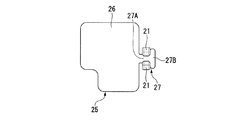
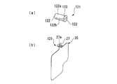
図12〜図15は、支持構造の変形例を示す概略構成図である。
例えば、先に示した各実施形態においては、撹拌板25A,25Bが装着部27側を上方にし、撹拌部26側を下方にした縦姿勢で支持柱21,21に支持される構成について述べたが、横姿勢で支持される構成にしても良い。つまり、図12に示すように、撹拌部26と装着部27との並びが水平状態となるように、支持柱21,21を上下に所定の間隔をあけて配置するようにしてもよい。
12 to 15 are schematic configuration diagrams showing modifications of the support structure.
For example, in each of the embodiments described above, the configuration in which the
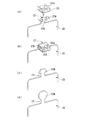
また、先に示した各実施形態においては、一対の支持柱21,21が、爪形状を呈する脱落防止部23,23を対向させた状態で互いに所定に間隔をおいて配置された構成となっていたが、図13(a)に示すように、ケース本体の左壁部から貯留室内に突出する軸体122と、軸体122の先端に設けられた複数の脱落防止部123,123とによって構成される支持柱(支持部)121であってもよい。軸体122は、基端側が一体とされた分岐部122a,122bによって構成されている。この支持柱121は、脱落防止部123,123の爪形状(突出)側が外側に向けられた状態となっており、分岐部122a,122bどうしが先端側にかけて広がっており、各々に設けられた脱落防止部123,123どうしが径方向に移動可能である。すなわち、これら分岐部122a,122bのそれぞれの先端に設けられた脱落防止部123,123(分岐部122a,122b)は、通常の状態において互いに離間しており、外力の負荷によって互いに近接可能となっている。
Moreover, in each embodiment shown previously, it becomes the structure by which a pair of
そして、このような支持柱121に撹拌板25をはめ込む際には、支持柱121の先端側の脱落防止部123,123(分岐部122a,122b)を撹拌板25の装着部27に形成された係合孔27a内に挿入させて、撹拌板25を分岐部122a,122bに係止させることにより支持柱121に撹拌板25が支持されることになる(図13(b))。このとき、分岐部122a,122bは、脱落防止部123,123側を近接させた状態で係合孔27a内を挿通し、係合孔27aを通過後に元の状態に復帰することによって、脱落防止部123,123が撹拌板25の装着部27に係止することになる。
When the stirring
撹拌板25を支持柱121に組み込む際、係合孔27aによって分岐部122a,122bが脱落防止部23,23どうしを互いに近接させるように撓むことにより、脱落防止部123,123が係合孔27a内を通過して、分岐部122a,122bに装着部27が係止することになる。係合孔27aを通過した脱落防止部123,123どうしが離間する(分岐部122a,122bの撓みが元に戻る)ことによって、撹拌板25が支持柱121に支持されることになる。
When the stirring
係合孔27aは、平面視略円形状を呈し、分岐部122a,122bが離間した状態の脱落防止部123,123どうしに装着部27が係合可能であるとともに、分岐部122a,122bに対して移動可能に支持される大きさ(直径)で形成されている。
The
なお、係合孔27aの平面視における形状は、円形状に係わらず、四角形状、矩形状など種々のものを採用することができる。
あるいは、基端側が一体とされた分岐部122a,122bを有する支持構造以外にも、単に、先に示した第1実施形態における支持柱21,21を、爪形状を呈した脱落防止部23,23どうしが互いに逆向きになるように配置させた支持構造としてもよい。
Note that the
Alternatively, in addition to the support structure having the
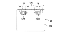
例えば、図14に示すように、撹拌板25における撹拌部126の一辺126aに沿って一対の係合孔126b,126bを一列に並べて形成しておき、これら一対の係合孔126b,126b内にそれぞれ一対の支持柱21,21を挿入させることによって、支持部20に撹拌板25を支持させる構成としてもよい。
For example, as shown in FIG. 14, a pair of
あるいは、係合孔126bごとに1本の支持柱21を設けてもよい。この場合、脱落防止部23を上方に向けた状態にし、各支持柱21,21の脱落防止部23,23に撹拌板25に設けられたそれぞれの係合孔126b,126bを係合させて取り付ける構成にしてもよい。
Alternatively, one
また、図15(a),(b)に示すように、ケース本体の左壁部から貯留室側に向かって垂直に突出するとともに、撹拌板25の装着部27の第2部位27Bを壁面方向に挿通して支持する貫通孔131aを有する支持部131を備えて構成されている。この場合、撹拌板25が可撓性を有する材料からなり、図15(a)に示すように装着部27の第2部位27Bを湾曲させた状態で貫通孔131a内に挿入させて、図15(b)に示すように元の状態に復帰させることで第2部位27Bが支持部131の上面が側に係合し、支持部131に撹拌板25が移動可能に支持されることとなる。
Further, as shown in FIGS. 15A and 15B, the
ここで、貫通孔131aの直径が、装着部27の第1部位27Aの幅W2(図4)よりも広く、第2部位27Bの幅W3(図4)よりも狭い寸法となっている。この貫通孔131aは、左壁部11e側へ向かって長さを有していても良い。これにより、撹拌板25が貫通孔131aの長さ方向に沿って移動可能となる。
Here, the diameter of the through
このような構成によっても、支持部131に対して確実に撹拌板25が支持されることになり、撹拌板25がキャリッジの移動に伴って揺動(移動)することが可能となる。
また、支持部131に対応する撹拌板25の構成としては、装着部27の第2部位27Bが図15(c)に示すように、装着部27における第2部位27bの先端側が貫通孔131aの直径よりも小さく構成され、貫通孔131a内に挿入しやすい構成とされていてもいいし、図15(d)に示すように平面視円形状とされていても良い。そして、貫通孔131a内に挿入された第2部位27bの一部が支持部131の上端面に係合することによって、撹拌板25が支持部131に支持される。
Even with such a configuration, the stirring
Further, as the configuration of the stirring
なお、上述した実施形態においては、液体噴射装置としてインクジェットプリンターを例にして説明したが、インクジェットプリンターに限られず、複写機及びファクシミリ等の装置であってもよい。
また、インクカートリッジCを装着する装置としては、液体噴射装置に限らず、液体を消費する装置であればよい。
In the above-described embodiment, the ink jet printer has been described as an example of the liquid ejecting apparatus. However, the liquid ejecting apparatus is not limited to the ink jet printer, and may be an apparatus such as a copying machine or a facsimile.
Further, the apparatus for mounting the ink cartridge C is not limited to the liquid ejecting apparatus, and any apparatus that consumes liquid may be used.
また、上述の実施形態においては、液体噴射装置として、インク等の液体を噴射する液体噴射装置を例にして説明したが、インク以外の他の液体を噴射したり吐出したりする液体噴射装置に適用することができる。液体噴射装置が噴射可能な液体は、機能材料の粒子が分散又は溶解されている液状体、ジェル状の流状体を含む。 In the above-described embodiment, the liquid ejecting apparatus that ejects a liquid such as ink has been described as an example of the liquid ejecting apparatus. However, the liquid ejecting apparatus ejects or discharges liquid other than ink. Can be applied. The liquid that can be ejected by the liquid ejecting apparatus includes a liquid material in which particles of the functional material are dispersed or dissolved, and a gel-like fluid.
また、上述した実施形態において、液体噴射装置から噴射される液体としては、インクのみならず、特定の用途に対応する液体を適用可能である。液体噴射装置に、その特定の用途に対応する液体を噴射可能な噴射ヘッドを設け、その噴射ヘッドから特定の用途に対応する液体を噴射して、その液体を所定の物体に付着させることによって、所定のデバイスを製造可能である。例えば、液体噴射装置は、液晶ディスプレイ、EL(エレクトロルミネッセンス)ディスプレイ、及び面発光ディスプレイ(FED)の製造等に用いられる電極材、色材等の材料を所定の分散媒(溶媒)に分散(溶解)した液体(液状体)を噴射する液体噴射装置に適用可能である。 In the above-described embodiment, as the liquid ejected from the liquid ejecting apparatus, not only ink but also a liquid corresponding to a specific application can be applied. By providing the liquid ejecting apparatus with an ejecting head capable of ejecting a liquid corresponding to the specific application, ejecting the liquid corresponding to the specific application from the ejecting head, and attaching the liquid to a predetermined object, A given device can be manufactured. For example, a liquid ejecting apparatus disperses (dissolves) a material such as an electrode material and a color material used in manufacturing a liquid crystal display, an EL (electroluminescence) display, and a surface emitting display (FED) in a predetermined dispersion medium (solvent). It is applicable to a liquid ejecting apparatus that ejects a liquid (liquid material).
液体収容容器として、走査型記録ヘッドを載置するキャリッジにインクカートリッジを装着する場合を例にして説明したが、これに限らない。例えば、キャリッジとは異なる位置にインクカートリッジを装着する場合(いわゆるオフキャリッジ型)であってもよい。
また、ライン型ヘッド(非走査型記録ヘッド)にインクカートリッジを装着する場合であってもよい。
Although the case where the ink cartridge is mounted on the carriage on which the scanning recording head is mounted as the liquid container has been described as an example, the present invention is not limited to this. For example, the ink cartridge may be mounted at a position different from the carriage (so-called off-carriage type).
Alternatively, the ink cartridge may be mounted on a line type head (non-scanning type recording head).
また、流体噴射装置としては、バイオチップ製造に用いられる生体有機物を噴射する液体噴射装置、精密ピペットとして用いられ試料となる液体を噴射する液体噴射装置であってもよい。
さらに、時計やカメラ等の精密機械にピンポイントで潤滑油を噴射する液体噴射装置、光通信素子等に用いられる微小半球レンズ(光学レンズ)などを形成するために紫外線硬化樹脂等の透明樹脂液を基板上に噴射する液体噴射装置、基板などをエッチングするために酸又はアルカリ等のエッチング液を噴射する液体噴射装置、ジェルを噴射する流状体噴射装置であってもよい。そして、これらのうちいずれか一種の液体収容容器、液体噴射装置に本発明を適用することができる。
In addition, the fluid ejecting apparatus may be a liquid ejecting apparatus that ejects a bio-organic matter used for biochip manufacturing, or a liquid ejecting apparatus that ejects a liquid that is used as a precision pipette as a sample.
In addition, transparent resin liquids such as UV curable resin to form liquid injection devices that pinpoint lubricant oil onto precision machines such as watches and cameras, and micro hemispherical lenses (optical lenses) used in optical communication elements. May be a liquid ejecting apparatus that ejects a liquid onto the substrate, a liquid ejecting apparatus that ejects an etching solution such as acid or alkali to etch the substrate, or a fluid ejecting apparatus that ejects gel. The present invention can be applied to any one of these types of liquid storage containers and liquid ejecting apparatuses.
1…プリンタ(液体噴射装置)、5…キャリッジ、6…記録ヘッド(液体噴射ヘッド)、10…ケース(容器)、11…ケース本体(容器本体)、11e…左壁部(壁面)、13A,13B…貯留室、19…ピン、20,20A,131…支持部、21,21a,21b,22,121…支持柱、21,121…支持柱、23,123…脱落防止部、24…傾斜面、25A,25B…撹拌板(撹拌部材)、26,126…撹拌部、27…装着部、27a,126b…係止孔、27A…第1部位(狭幅部)、27B…第2部位(係止部)、28…貫通部、28A…開口、K…インク(液体)、L1,L2…間隔、W1,W2,W3,W4,W5…幅、122…軸体、126b…係合孔、126a…一辺、131a…貫通孔、C…インクカートリッジ(液体収容容器) DESCRIPTION OF SYMBOLS 1 ... Printer (liquid ejecting apparatus), 5 ... Carriage, 6 ... Recording head (liquid ejecting head), 10 ... Case (container), 11 ... Case main body (container main body), 11e ... Left wall part (wall surface), 13A, 13B ... Reservoir, 19 ... Pin, 20, 20A, 131 ... Support part, 21, 21a, 21b, 22, 121 ... Support pillar, 21, 121 ... Support pillar, 23, 123 ... Drop-off prevention part, 24 ... Inclined surface , 25A, 25B ... stirring plate (stirring member), 26, 126 ... stirring portion, 27 ... mounting portion, 27a, 126b ... locking hole, 27A ... first portion (narrow width portion), 27B ... second portion (engagement) 28) penetrating part, 28A ... opening, K ... ink (liquid), L1, L2 ... spacing, W1, W2, W3, W4, W5 ... width, 122 ... shaft body, 126b ... engagement hole, 126a ... One side, 131a ... Through hole, C ... Ink cartridge Di (liquid container)
Claims (11)
前記貯留室内に配設されて前記液体を撹拌する撹拌部材と、
前記撹拌部材を移動可能に支持するとともに前記容器と一体的に形成された支持構造と、を備え、
前記撹拌部材は、前記液体を撹拌する撹拌部と、前記撹拌部から延出する狭幅部および前記狭幅部の前記撹拌部とは反対側に設けられた係止部からなる装着部と、を有し、
前記支持構造は、前記容器の壁部から前記貯留室内に突出し、前記係止部を挿通して支持する貫通部を形成する支持部を備えた
ことを特徴とする液体収容容器。 A container body for storing liquid in a storage chamber formed in the container;
A stirring member disposed in the storage chamber and stirring the liquid;
A support structure that movably supports the stirring member and is formed integrally with the container,
The stirring member includes a stirring portion that stirs the liquid, a narrow portion that extends from the stirring portion, and a mounting portion that includes a locking portion provided on the opposite side of the stirring portion of the narrow portion; Have
The liquid storage container according to claim 1, wherein the support structure includes a support part that protrudes from the wall part of the container into the storage chamber and forms a penetrating part that inserts and supports the locking part.
前記支持部が鉤形の一対の支持柱を対向させて構成されていることを特徴とする請求項1に記載の液体収容容器。 The support structure has an opening that penetrates the outer periphery of the support part and the penetrating part,
The liquid container according to claim 1, wherein the support portion is configured by opposing a pair of bowl-shaped support columns.
前記貫通部の直径が、前記狭幅部の幅よりも広く、前記係止部の前記幅よりも狭くなるように形成されている
ことを特徴とする請求項1または2に記載の液体収容容器。 The mounting portion has a width of the narrow width portion in a direction orthogonal to the direction in which the mounting portion and the stirring portion are arranged, smaller than the width of the locking portion,
3. The liquid container according to claim 1, wherein a diameter of the penetrating portion is wider than a width of the narrow width portion and narrower than the width of the locking portion. .
ことを特徴とする請求項3に記載の液体収容容器。 4. The pair of support columns are arranged such that a gap between drop-off prevention portions having a claw shape provided at each tip is narrower than the width of the narrow width portion. The liquid container described in 1.
ことを特徴とする請求項2から4のいずれか一項に記載の液体収容容器。 5. The inclined surface is formed on each of the pair of support columns so as to increase a distance from the other support columns adjacent to the tip. The liquid container described in 1.
前記支持部が前記装着部の数に応じて複数設けられていることを特徴とする請求項1から5のいずれか一項に記載の液体収容容器。 A plurality of the mounting parts are provided in a line along one side of the stirring part,
The liquid container according to claim 1, wherein a plurality of the support portions are provided according to the number of the mounting portions.
前記貯留室内に配設されて前記液体を撹拌する撹拌部材と、
前記撹拌部材を移動可能に支持するとともに前記容器と一体的に形成された支持構造と、を備え、
前記支持構造は、前記容器の壁面から前記貯留室内に突出する軸体と、当該軸体の先端に設けられ前記軸体の径方向に移動可能な複数の脱落防止部と、を有する支持部を有し、
前記撹拌部材は、前記液体を撹拌するとともに前記脱落防止部を挿通可能な係止孔を有する撹拌部を有する
ことを特徴とする液体収容容器。 A container body for storing liquid in a storage chamber formed in the container;
A stirring member disposed in the storage chamber and stirring the liquid;
A support structure that movably supports the stirring member and is formed integrally with the container,
The support structure includes a support body having a shaft body that protrudes from the wall surface of the container into the storage chamber, and a plurality of drop-off prevention portions that are provided at a distal end of the shaft body and are movable in a radial direction of the shaft body. Have
The liquid storage container, wherein the stirring member has a stirring portion that has a locking hole for stirring the liquid and allowing the drop-off preventing portion to be inserted therethrough.
前記支持部が前記係止孔の数に応じて複数設けられている
ことを特徴とする請求項1から5または請求項7に記載の液体収容容器。 A plurality of the locking holes are provided in a line along one side of the stirring unit,
The liquid container according to claim 1, wherein a plurality of the support portions are provided according to the number of the locking holes.
前記撹拌部材には前記ピンを挿入可能な挿入孔が形成されている
ことを特徴とする請求項1から請求項8のいずれか一項に記載の液体収容容器。 Having a pin integrally formed with the container;
The liquid container according to any one of claims 1 to 8, wherein an insertion hole into which the pin can be inserted is formed in the stirring member.
前記液体収容容器として、請求項1から請求項9のいずれか一項に記載の液体収容容器を用いることを特徴とする液体噴射装置。 In a liquid ejecting apparatus in which a liquid container and a liquid ejecting head are mounted on a carriage that reciprocates along the main scanning direction, and liquid is supplied from the liquid containing container to the liquid ejecting head.
A liquid ejecting apparatus using the liquid container according to claim 1 as the liquid container.
Priority Applications (1)
| Application Number | Priority Date | Filing Date | Title |
|---|---|---|---|
| JP2010162539A JP5678500B2 (en) | 2010-07-20 | 2010-07-20 | Liquid container and liquid ejecting apparatus |
Applications Claiming Priority (1)
| Application Number | Priority Date | Filing Date | Title |
|---|---|---|---|
| JP2010162539A JP5678500B2 (en) | 2010-07-20 | 2010-07-20 | Liquid container and liquid ejecting apparatus |
Publications (2)
| Publication Number | Publication Date |
|---|---|
| JP2012024931A true JP2012024931A (en) | 2012-02-09 |
| JP5678500B2 JP5678500B2 (en) | 2015-03-04 |
Family
ID=45778483
Family Applications (1)
| Application Number | Title | Priority Date | Filing Date |
|---|---|---|---|
| JP2010162539A Expired - Fee Related JP5678500B2 (en) | 2010-07-20 | 2010-07-20 | Liquid container and liquid ejecting apparatus |
Country Status (1)
| Country | Link |
|---|---|
| JP (1) | JP5678500B2 (en) |
Citations (7)
| Publication number | Priority date | Publication date | Assignee | Title |
|---|---|---|---|---|
| JP2004218663A (en) * | 2003-01-09 | 2004-08-05 | Denso Corp | Case coupling structure |
| JP2007062336A (en) * | 2005-09-02 | 2007-03-15 | Canon Inc | Ink tank and recording device |
| JP2007090872A (en) * | 2005-09-02 | 2007-04-12 | Canon Inc | Liquid storage container |
| JP2007230189A (en) * | 2006-03-03 | 2007-09-13 | Canon Inc | Ink tank and recording device |
| JP2007301859A (en) * | 2006-05-11 | 2007-11-22 | Canon Inc | Liquid storage container and recording apparatus |
| JP2008111463A (en) * | 2006-10-30 | 2008-05-15 | Ykk Corp | Coupler |
| JP2010052377A (en) * | 2008-08-29 | 2010-03-11 | Canon Inc | Ink tank |
-
2010
- 2010-07-20 JP JP2010162539A patent/JP5678500B2/en not_active Expired - Fee Related
Patent Citations (7)
| Publication number | Priority date | Publication date | Assignee | Title |
|---|---|---|---|---|
| JP2004218663A (en) * | 2003-01-09 | 2004-08-05 | Denso Corp | Case coupling structure |
| JP2007062336A (en) * | 2005-09-02 | 2007-03-15 | Canon Inc | Ink tank and recording device |
| JP2007090872A (en) * | 2005-09-02 | 2007-04-12 | Canon Inc | Liquid storage container |
| JP2007230189A (en) * | 2006-03-03 | 2007-09-13 | Canon Inc | Ink tank and recording device |
| JP2007301859A (en) * | 2006-05-11 | 2007-11-22 | Canon Inc | Liquid storage container and recording apparatus |
| JP2008111463A (en) * | 2006-10-30 | 2008-05-15 | Ykk Corp | Coupler |
| JP2010052377A (en) * | 2008-08-29 | 2010-03-11 | Canon Inc | Ink tank |
Also Published As
| Publication number | Publication date |
|---|---|
| JP5678500B2 (en) | 2015-03-04 |
Similar Documents
| Publication | Publication Date | Title |
|---|---|---|
| CN104723684B (en) | liquid supply unit | |
| CN103203998B (en) | Liquid container and liquid consumption apparatus | |
| JP6443480B2 (en) | cartridge | |
| CN101070013A (en) | Liquid container, head cartridge, ink jet printing apparatus, and stirring method for liquid container | |
| CN103204005A (en) | Cartridge and printing material supply system | |
| EP2159061A1 (en) | Fluid injecting apparatus, and its manufacturing method | |
| JPWO2017115582A1 (en) | Liquid supply unit | |
| WO2017115583A1 (en) | Liquid supply unit | |
| CN108724955B (en) | Liquid supply unit | |
| JP5880054B2 (en) | Printing apparatus and printing material supply system | |
| JP2019093618A (en) | Liquid jet device | |
| JP5678500B2 (en) | Liquid container and liquid ejecting apparatus | |
| JP4916190B2 (en) | Ink tank and printer | |
| CN110341316B (en) | liquid ejection device | |
| JP5768325B2 (en) | Liquid container and liquid ejecting apparatus | |
| JP5919858B2 (en) | Liquid container and liquid consuming device | |
| WO2017090374A1 (en) | Liquid supply unit and liquid ejection device | |
| JP5663971B2 (en) | Fluid ejection device | |
| JP2007136748A (en) | Liquid ejector | |
| JP5888362B2 (en) | Printing apparatus and printing material supply system | |
| JP5831266B2 (en) | Method for manufacturing liquid container | |
| CN108973335A (en) | liquid tank | |
| JP2019084694A (en) | cartridge | |
| JP2012035429A (en) | Liquid storage container and liquid consumption device | |
| JP2018030333A (en) | Liquid ejector |
Legal Events
| Date | Code | Title | Description |
|---|---|---|---|
| A621 | Written request for application examination |
Free format text: JAPANESE INTERMEDIATE CODE: A621 Effective date: 20130321 |
|
| A977 | Report on retrieval |
Free format text: JAPANESE INTERMEDIATE CODE: A971007 Effective date: 20131220 |
|
| A131 | Notification of reasons for refusal |
Free format text: JAPANESE INTERMEDIATE CODE: A131 Effective date: 20140107 |
|
| A521 | Request for written amendment filed |
Free format text: JAPANESE INTERMEDIATE CODE: A523 Effective date: 20140307 |
|
| TRDD | Decision of grant or rejection written | ||
| A01 | Written decision to grant a patent or to grant a registration (utility model) |
Free format text: JAPANESE INTERMEDIATE CODE: A01 Effective date: 20141209 |
|
| A61 | First payment of annual fees (during grant procedure) |
Free format text: JAPANESE INTERMEDIATE CODE: A61 Effective date: 20141222 |
|
| R150 | Certificate of patent or registration of utility model |
Ref document number: 5678500 Country of ref document: JP Free format text: JAPANESE INTERMEDIATE CODE: R150 |
|
| S531 | Written request for registration of change of domicile |
Free format text: JAPANESE INTERMEDIATE CODE: R313531 |
|
| R350 | Written notification of registration of transfer |
Free format text: JAPANESE INTERMEDIATE CODE: R350 |
|
| LAPS | Cancellation because of no payment of annual fees |