JP4916190B2 - Ink tank and printer - Google Patents
Ink tank and printer Download PDFInfo
- Publication number
- JP4916190B2 JP4916190B2 JP2006058378A JP2006058378A JP4916190B2 JP 4916190 B2 JP4916190 B2 JP 4916190B2 JP 2006058378 A JP2006058378 A JP 2006058378A JP 2006058378 A JP2006058378 A JP 2006058378A JP 4916190 B2 JP4916190 B2 JP 4916190B2
- Authority
- JP
- Japan
- Prior art keywords
- ink
- storage chamber
- ink tank
- tank
- carriage
- Prior art date
- Legal status (The legal status is an assumption and is not a legal conclusion. Google has not performed a legal analysis and makes no representation as to the accuracy of the status listed.)
- Expired - Fee Related
Links
Images


Classifications
-
- B—PERFORMING OPERATIONS; TRANSPORTING
- B01—PHYSICAL OR CHEMICAL PROCESSES OR APPARATUS IN GENERAL
- B01F—MIXING, e.g. DISSOLVING, EMULSIFYING OR DISPERSING
- B01F31/00—Mixers with shaking, oscillating, or vibrating mechanisms
- B01F31/20—Mixing the contents of independent containers, e.g. test tubes
- B01F31/24—Mixing the contents of independent containers, e.g. test tubes the containers being submitted to a rectilinear movement
-
- B—PERFORMING OPERATIONS; TRANSPORTING
- B01—PHYSICAL OR CHEMICAL PROCESSES OR APPARATUS IN GENERAL
- B01F—MIXING, e.g. DISSOLVING, EMULSIFYING OR DISPERSING
- B01F31/00—Mixers with shaking, oscillating, or vibrating mechanisms
- B01F31/42—Mixers with shaking, oscillating, or vibrating mechanisms with pendulum stirrers, i.e. with stirrers suspended so as to oscillate about fixed points or axes
Description
本発明は、インクタンクおよびそのインクタンクを用いるプリンタに関するものである。 The present invention relates to an ink tank and a printer using the ink tank.
インクタンクに収容されているインクを用いる記録装置としては、例えば、インクを吐出可能なインクジェット記録ヘッドを用いるインクジェット記録装置がある。さらに、このようなインクジェット記録装置には、インクジェット記録ヘッドと共にインクタンクをキャリッジに搭載して、そのキャリッジの主走査方向への移動に伴って、記録媒体上に画像を記録するシリアルスキャンタイプのものがある。 An example of a recording apparatus that uses ink stored in an ink tank is an inkjet recording apparatus that uses an inkjet recording head capable of ejecting ink. Further, such an ink jet recording apparatus is of a serial scan type in which an ink tank is mounted on a carriage together with an ink jet recording head, and an image is recorded on a recording medium as the carriage moves in the main scanning direction. There is.
このシリアルスキャンタイプのインクジェット記録装置は、インクジェット記録ヘッドと、その記録ヘッドにインクを供給するインクタンクと、を搭載可能なキャリッジを備えている。そして記録に際しては、記録媒体に対してキャリッジを移動させながら、記録ヘッドに設けられた微細な吐出口からインク滴を吐出させ、そのインク滴を記録媒体上に着弾させることにより、所望の画像を記録する。 This serial scan type inkjet recording apparatus includes a carriage capable of mounting an inkjet recording head and an ink tank that supplies ink to the recording head. During recording, while moving the carriage with respect to the recording medium, ink droplets are ejected from fine ejection ports provided in the recording head, and the ink droplets are landed on the recording medium, thereby obtaining a desired image. Record.
インクジェット記録ヘッドに用いられるインクとしては、主に、着色材として染料を用いた染料インクが使用されてきた。しかしながら、染料インクによって記録された記録物は、耐光性および耐候性を重視する屋外掲示プリント物等の用途において求められる性能をもつことが難しく、その代わりに、着色材として顔料を用いた顔料インクが実用化されている。しかし、顔料は溶解系ではなく分散系であるため、顔料インクは、インクタンク中において顔料粒子の沈降が生じることが避けられない。 As an ink used for an ink jet recording head, a dye ink using a dye as a coloring material has been mainly used. However, it is difficult for the recorded matter recorded with the dye ink to have the performance required for uses such as outdoor posted printed matter that places importance on light resistance and weather resistance. Instead, pigment ink using a pigment as a coloring material Has been put to practical use. However, since the pigment is not a dissolution system but a dispersion system, the pigment ink is unavoidably caused by precipitation of pigment particles in the ink tank.
例えば、インクタンクがインクジェット記録装置に装着されたまま長期間放置された場合には、そのインクタンクの内部にてインク中の顔料粒子が徐々に沈降する。そのため、インクタンク内部において、その底部から上部に向かうに従って顔料粒子の濃度勾配が発生する。その結果、インクタンク底部近傍のインクは、顔料粒子濃度が高くなって色が濃い層を形成し、一方、インクタンク上部のインクは、顔料粒子濃度が低くなって色が薄い層を形成することになる。 For example, when the ink tank is left in the ink jet recording apparatus for a long period of time, the pigment particles in the ink gradually settle inside the ink tank. Therefore, a concentration gradient of pigment particles is generated in the ink tank from the bottom to the top. As a result, the ink near the bottom of the ink tank has a high pigment particle concentration and forms a dark color layer, while the ink at the top of the ink tank has a low pigment particle concentration and forms a light color layer. become.
インクタンク内のインクがインクタンク底部から導出される場合、そのインクタンクから導出したインクを記録ヘッドに供給したときには、最初に、顔料粒子濃度の高い層を形成するインクが供給されて、色が濃い画像が記録されることになる。つまり、インクタンクの使用初期における記録画像と、その使用後期における記録画像との間に、目視によって認識される程度の記録濃度の差が生じるおそれがある。このような現象は、色の濃淡によってカラー画像を記録するカラー記録において、特に顕著となる。 When the ink in the ink tank is derived from the bottom of the ink tank, when the ink derived from the ink tank is supplied to the recording head, first, ink that forms a layer having a high pigment particle concentration is supplied, and the color changes. A dark image will be recorded. In other words, there is a possibility that a difference in recording density to the extent that it can be recognized visually is produced between the recorded image in the initial use of the ink tank and the recorded image in the latter stage of use. Such a phenomenon becomes particularly remarkable in color recording in which a color image is recorded based on color shading.
特許文献1,2には、インクタンク内に攪拌体を備え、キャリッジの往復運動の慣性力によって攪拌体を移動させることにより、インクタンク内のインクを攪拌させる構成が記載されている。
すなわち特許文献1には、内部に、攪拌体を揺動自在に備えたインクタンクが記載されており、その攪拌体の揺動中心は、キャリッジ移動方向におけるインクタンク内のほぼ中央の位置に設定されている。その攪拌体は、キャリッジの往復運動によって、一方向および他方向に同様に揺動することになる。また特許文献2には、内部に、弾性変形を伴って揺動自在の攪拌体を備えたインクタンクが記載されており、その攪拌体は、インクタンクの上部内面のほぼ中央部分から垂下する形状となっている。その攪拌体も、キャリッジの往復運動によって、一方向および他方向に同様に揺動することになる。また特許文献2には、インクタンク内に、その底面上を自由に移動可能な攪拌体を備えた構成も記載されている。その攪拌体は、キャリッジの往復運動によって、インクタンクの底面上を自由に移動することになる。
That is, Patent Document 1 describes an ink tank provided with a stirring body in a swingable manner, and the center of swinging of the stirring body is set at a substantially central position in the ink tank in the carriage movement direction. Has been. The stirrer similarly swings in one direction and the other direction by the reciprocating motion of the carriage.
しかしながら、特許文献1,2に記載されているインクタンクには、次のような不具合がある。
However, the ink tanks described in
まず、特許文献1に記載のインクタンクは、インクタンク内のほぼ中央部分を中心として攪拌体が一方向および他方向に同様に揺動する。そのため、その攪拌体の揺動範囲を大きくして攪拌性能を上げるためには、キャリッジの移動方向におけるインクタンクの幅を大きくする必要がある。しかし、キャリッジに搭載されるインクタンクは、キャリッジの移動方向に沿って複数搭載される場合が多く、その幅が比較的小さく制限されているため、攪拌体の揺動範囲を大きくすることができず、その攪拌体の揺動によって生じるインクの流れが小さい。インクを充分に攪拌するためには、キャリッジの往復移動回数を多くして、攪拌時間を長くする必要がある。 First, in the ink tank described in Patent Document 1, the stirrer similarly swings in one direction and the other direction around the substantially central portion in the ink tank. Therefore, in order to increase the agitation range of the agitator and improve the agitation performance, it is necessary to increase the width of the ink tank in the carriage movement direction. However, a plurality of ink tanks mounted on the carriage are often mounted along the moving direction of the carriage, and the width of the ink tank is limited to be relatively small, so that the swing range of the stirring member can be increased. However, the ink flow generated by the shaking of the stirring member is small. In order to sufficiently stir the ink, it is necessary to increase the number of times the carriage is reciprocated and lengthen the stirring time.
一方、特許文献2に記載のインクタンクにおいて、インクタンクの上部内面のほぼ中央部分から垂下する攪拌体を備えるものは、インクタンク内のほぼ中央部分を中心として攪拌体が一方向および他方向に揺動する。攪拌体の揺動範囲を大きくして攪拌性能を上げるためには、特許文献1のインクタンクと同様に、キャリッジの移動方向におけるインクタンクの幅を大きくする必要がある。そのため、特許文献1のインクタンクと同様の問題がある。また、攪拌体を大きく弾性変形させるためにキャリッジの加速度を大きく設定した場合には、キャリッジの駆動モーターの大型化および高価格化を招くと共に、記録装置の振動が大きくなるおそれもある。また特許文献2に記載のインクタンクにおいて、その底面上を自由に移動可能な攪拌体を備えたものは、その攪拌体がインクタンク内のインクの上層部分から離れているため、その上層部分に対しての攪拌性能が劣るという問題がある。
On the other hand, in the ink tank described in
このような特許文献1および2に記載のインクタンクの不具合は、次のような一般的なインクタンクおよび記録装置の形態の観点からも明らかである。
Such problems of the ink tanks described in
一般的に、キャリッジに搭載されるインクタンク(「オンキャリッジタイプのインクタンク」ともいう)は、その着脱の操作性を良くするために、その幅と長さが設定されている。すなわち、キャリッジの移動方向(主走査方向)におけるインクタンクの幅は比較的小さく、また、その主走査方向と交差する記録媒体の搬送方向(副走査方向)におけるインクタンクの長さは比較的大きく設定されている。そのため、攪拌体の変位方向である主走査方向において、その変位量を大きく設定することができない。従って、攪拌体の変位量が小さくてインクの強い流れを生じさせることができず、そのためインクの攪拌効率が劣り、インクタンク内部のインク全体を攪拌するためには時間が掛かりすぎる。例えば、キャリッジにインクタンクを装着したまま、記録装置が長期間記録を行わなかったために、インクタンク内におけるインク中の顔料粒子が沈降した場合には、記録の開始前に長時間に渡って、キャリッジを往復運動させなければならない。そのため、記録動作が可能となるまでのウォームアップ時間が長くなる。特に、顔料インク中の顔料粒径が大きい場合や顔料粒子の比重が大きい場合には、その沈降が早く、インクタンクを数日間放置しただけでも、記録画像に悪影響を与える濃度分布がインクタンク内に発生するおそれがある。この場合には、数日毎にインクの攪拌動作を行わなければならず、また、その攪拌動作の間は記録を開始することができなくなる。 In general, the width and length of an ink tank (also referred to as an “on-carriage type ink tank”) mounted on a carriage is set in order to improve detachability. That is, the width of the ink tank in the carriage movement direction (main scanning direction) is relatively small, and the length of the ink tank in the recording medium conveyance direction (sub-scanning direction) intersecting with the main scanning direction is relatively large. Is set. Therefore, the amount of displacement cannot be set large in the main scanning direction, which is the displacement direction of the stirrer. Therefore, the amount of displacement of the stirrer is small, and a strong ink flow cannot be generated. Therefore, the ink stirring efficiency is poor, and it takes too much time to stir the entire ink inside the ink tank. For example, if the recording device did not perform recording for a long time with the ink tank mounted on the carriage, and the pigment particles in the ink in the ink tank settled, for a long time before the start of recording, The carriage must be reciprocated. For this reason, the warm-up time until the recording operation becomes possible becomes longer. In particular, when the pigment particle size in the pigment ink is large or the specific gravity of the pigment particles is large, the sedimentation is quick, and even if the ink tank is left for a few days, the density distribution that adversely affects the recorded image is present in the ink tank. May occur. In this case, the ink stirring operation must be performed every few days, and recording cannot be started during the stirring operation.
また、インクタンクの記録ヘッドへのインク供給口がインク保持部の下部にある場合には、さらに別の課題が生じる。これを説明するために、まず、インクの沈降状態について詳しく説明する。 Further, when the ink supply port to the recording head of the ink tank is at the lower part of the ink holding part, another problem arises. In order to explain this, first, the ink settling state will be described in detail.
図5にインクタンク内の高さ位置におけるインク濃度を示す。インクタンクの使用初期などにおいて、インクがインクタンクの底部に沈降していない場合、インク濃度はインクの高さに依らず同一の濃度となる。しかしながら、供給口を下向きにして長期間保存すると、図の曲線Lのようにタンク内の高い位置に収容されているインクは濃度が低くなる。そして、インクタンク内の低い位置に収容されているインクには濃度の高い部分が生じる。特にインクタンクの最下面(底部)に近いところでは急激に濃度が変化(増大)する。一般に顔料粒子の濃度が高い程、インクは高粘度となるため、最下層の部分はそれ以外の部分に比べて比重が高く粘度も高くなり、他の部分とは物性的に大きく異なる層を形成することとなる。 FIG. 5 shows the ink density at the height position in the ink tank. If the ink does not settle at the bottom of the ink tank in the initial stage of use of the ink tank, the ink density is the same regardless of the height of the ink. However, when stored for a long time with the supply port facing downward, the concentration of the ink stored at a high position in the tank as shown by the curve L in the figure decreases. And the high density part arises in the ink accommodated in the low position in an ink tank. In particular, the density rapidly changes (increases) near the bottom surface (bottom) of the ink tank. In general, the higher the concentration of pigment particles, the higher the viscosity of the ink, so the lowermost layer has a higher specific gravity and higher viscosity than the rest, forming a layer that is physically different from the other parts. Will be.
このように、インクタンクの下層部分に沈降するインクの比重および粘度が増大することにより、記録ヘッドへのインク供給口がインクタンクの下部に形成されている場合には、次のような2つの課題が生じる。
1つ目の課題は、インク収納室内下層の沈降インクは比重が高いため、更に低い位置に移動してインク供給口の内部へと侵入することである。インク供給口内部へは攪拌体により発生するインクの流れが到達しづらく、充分に攪拌することができない。従って、インク供給口内部へ侵入した沈降インクは、吸引回復等により外部に排出せざるを得ず、無駄にインクを廃棄することになり、ランニングコストの増大を招く。
As described above, when the specific gravity and viscosity of the ink settled in the lower layer portion of the ink tank are increased, and the ink supply port to the recording head is formed at the lower portion of the ink tank, the following two Challenges arise.
The first problem is that the settled ink in the lower layer of the ink storage chamber has a high specific gravity, so that it moves to a lower position and enters the ink supply port. The ink flow generated by the stirrer does not easily reach the inside of the ink supply port, and cannot be sufficiently stirred. Therefore, the sedimented ink that has entered the ink supply port must be discharged to the outside due to suction recovery or the like, and the ink is discarded wastefully, resulting in an increase in running cost.
2つ目の課題は、インク収納室内下層部の沈降インクは粘度が高いため、攪拌体によって生じるインクの流れが減速され、十分な攪拌状態を得るためには多くの時間を要することである。つまり、インクタンクの底部に沈降したインクを攪拌し、インクタンク内のインク濃度を均一化するまでに多くの時間を要することから、記録装置を起動してから記録動作が開始されるまでに多くの待機時間が必要となる。 The second problem is that the sedimented ink in the lower layer of the ink containing chamber has a high viscosity, so that the flow of ink generated by the stirring body is decelerated, and it takes a lot of time to obtain a sufficient stirring state. In other words, since it takes a lot of time to stir the ink that has settled at the bottom of the ink tank and uniformize the ink density in the ink tank, there is much time until the recording operation is started after the recording device is started. Waiting time is required.
本発明の目的は、インクタンク内のインクを効率よく攪拌することができるインクタンク、および均一な濃度のインクによって高品位の画像を記録することができる記録装置を提供することにある。 An object of the present invention is to provide an ink tank that can efficiently stir the ink in the ink tank, and a recording apparatus that can record a high-quality image with a uniform concentration of ink.
上記課題を解決するため、本発明は以下の構成を有する。
本発明の第1の形態は、プリンタに装着されるインクタンクであって、インクを収納するインク収納室と、前記インク収納室の内壁に備えられ、前記インク収納室の内部に突出する突出部材と、該突出部材に係合される係合部を有する攪拌部材と、前記インク収納室の内部に設けられるインク導出口と、前記インクタンクの外側に設けられるインク供給口と、前記インク導出口と前記インク供給口とをつなぎ、前記インク収納室内のインクを前記インクタンク外へ供給する際の流路となるインク導出流路と、を備え、前記インク導出口は、前記インクタンクが前記プリンタに装着される姿勢において、前記インク収納室の内壁の最下面より上方に配され、前記攪拌部材は前記係合部を回動軸として回動し、かつ、前記突出部材が突出する方向に沿って前記係合部は移動することを特徴とする。
In order to solve the above problems, the present invention has the following configuration.
A first aspect of the present invention is an ink tank that is mounted on a printer, and includes an ink storage chamber that stores ink, and a protruding member that is provided on an inner wall of the ink storage chamber and protrudes into the ink storage chamber A stirring member having an engaging portion engaged with the protruding member, an ink outlet provided in the ink storage chamber, an ink supply port provided outside the ink tank, and the ink outlet and connects with the ink supply port, the ink of the ink containing chamber and an ink outlet passage comprising a flow path in supplying to the ink tank outside the ink outlet port, the ink tank is the printer in the posture to be attached to, is arranged from above the lowermost surface of the inner wall of the ink accommodating chamber, the stirring member rotates the engaging portion as a rotation axis, and a direction in which the protruding member protrudes The engaging portion along is characterized that you move.
本発明の第2の形態は、プリントに使用される顔料成分を含む顔料インクを収納するインクタンク及び該液体を吐出するヘッドを搭載して往復移動するキャリッジを有するプリンタにおいて、前記インクタンクは、インクを収納するインク収納室と、記インク収納室の内壁に備えられ、前記インク収納室の内部に突出する突出部材と、該突出部材に係合される係合部を有する攪拌部材と、前記インク収納室の内部に設けられるインク導出口と、前記インクタンクの外側に設けられるインク供給口と、前記インク導出口と前記インク供給口とをつなぎ、前記インク収納室内のインクを前記インクタンク外へ供給する際の流路となるインク導出流路と、を備え、前記インク導出口は、前記インクタンクが前記キャリッジに搭載される姿勢において、前記インク収納室の内壁の最下面より上方に配され、
前記キャリッジの往復移動に伴って、前記攪拌部材は前記係合部を回動軸として回動し、かつ、前記突出部材が突出する方向に沿って前記係合部は移動することを特徴とする。
According to a second aspect of the present invention, there is provided a printer having an ink tank that stores a pigment ink containing a pigment component used for printing and a carriage that reciprocates by mounting a head that discharges the liquid. An ink storage chamber for storing ink, a protruding member provided on an inner wall of the ink storage chamber, protruding into the ink storage chamber, and an agitation member having an engaging portion engaged with the protruding member; An ink outlet port provided inside the ink storage chamber, an ink supply port provided outside the ink tank, and the ink outlet port and the ink supply port are connected, and the ink in the ink storage chamber is removed from the ink tank. and an ink outlet passage comprising a flow path in supplying to the ink outlet port, in the attitude of the ink tank is mounted on the carriage Arranged above the lowermost surface of the inner wall of the ink storage chamber,
As the carriage reciprocates, the stirring member rotates about the engaging portion as a rotation shaft, and the engaging portion moves along a direction in which the protruding member protrudes. .
本発明によれば、インク収納室内に配置された記録ヘッドへインクを供給するためのインク導出口が、インク収納室の最も下方に位置する部分より上方に位置している。色材の沈降した高濃度、高粘度のインクがインク供給口に供給されるのを低減することができる。 According to the present invention, the ink outlet for supplying ink to the recording head disposed in the ink storage chamber is positioned above the lowest position of the ink storage chamber. It is possible to reduce the supply of the high-concentration and high-viscosity ink in which the color material is precipitated to the ink supply port.
従って、本発明によれば、プリンタを起動した後に、素早く記録動作を開始することができ、さらには、長期間放置後の記録開始時に排出すべきインクを少量に抑えることができ、ランニングコストを低減することも可能になる。 Therefore, according to the present invention, after the printer is started, the recording operation can be started quickly, and furthermore, the amount of ink to be discharged at the start of recording after being left for a long time can be suppressed to a small amount, thereby reducing the running cost. It can also be reduced.
以下、図面を参照して本発明の実施形態について説明する。
[第1の実施形態]
(インクタンクの構成)
図1は、本発明の第1の実施形態におけるインクタンク1の断面図であり、図2は、そのインクタンク1の斜視図である。図1は、図2のI−I線に沿う断面図に相当する。図3はインクタンク1の分解斜視図である。また、図4はタンクケース(タンク本体)10に攪拌部材20A,20Bを組付けた状態を示す斜視図である。
Hereinafter, embodiments of the present invention will be described with reference to the drawings.
[First Embodiment]
(Ink tank configuration)
FIG. 1 is a cross-sectional view of an ink tank 1 according to the first embodiment of the present invention, and FIG. 2 is a perspective view of the ink tank 1. 1 corresponds to a cross-sectional view taken along the line II in FIG. FIG. 3 is an exploded perspective view of the ink tank 1. FIG. 4 is a perspective view showing a state in which the stirring
図1および図2において、インクタンク1は、タンクケース10と可撓性部材40によって構成されるインク収納室R内にインク2を収納する容器であり、図1のようにインク供給口60を下方に向けた姿勢でインクジェット記録装置に装着される。インク供給口60は、インクジェット記録ヘッド(不図示)のインク供給路に接続されると共に、インク収納室R内に形成されたインク導出路66に連通している。このインク導出部66の上端部には、インク収容室Rに連通するインク導出口64が形成されている。本例におけるインク導出路66は、タンクケース10の底壁部10Bから上方に立ち上がった導出流路壁10Cによって囲まれた空間からなる。そして、この導出路壁10Cの上端の開口部が前記のインク導出口64となっている。また、タンクケース10の底壁部は、インク収容室Rの底部をも形成している。
なお、本例のインクタンク1は、記録ヘッドと分離可能となっている。しかしインクタンク1は、記録ヘッドを分離不能に備えた記録ヘッド一体型のものであっても良い。
1 and 2, the ink tank 1 is a container that stores the
The ink tank 1 of this example can be separated from the recording head. However, the ink tank 1 may be a recording head integrated type in which the recording head is provided so as not to be separated.
図3に示すように、インクタンク1は、主に、タンクケース10、攪拌部材20A,20B、ばね部材30、圧力板31、可撓性部材40、蓋部材50、毛管部材61、メニスカス保持部材62、および供給口部材63を有する構成となっている。タンクケース10、蓋部材50および供給口部材63は、インクタンク1の筐体を構成する。
As shown in FIG. 3, the ink tank 1 mainly includes a
タンクケース10の下端部には、供給口部材63が固定されている。この供給口部材63には、インクジェット記録ヘッドに接続可能なインク供給口60が形成されている。インク供給口60には、これを閉塞するように、毛管部材61とメニスカス保持部材62とが備えられている。毛管部材61は、インク供給口60に記録ヘッドを接続したときに、その記録ヘッドの鉛直方向(図1中の上下方向)の位置ずれを吸収できるように、ある程度の柔軟性をもつ材料によって構成されている。さらに、この毛管部材61は、インクの流路となるような毛管力を持つ。インク収納室R内は、後述するように、インク供給口60からインクが垂れ出ないように負圧に保たれている。メニスカス保持部材62は、そのインク収納室R内の負圧によって、インク供給口60から気泡を引き込まないように、インクのメニスカスを発生する。従ってメニスカス保持部材62としては、インク収納室R内に発生する負圧の最大値よりも強いメニスカス保持圧力を発生させるような部材が選択される。
A
タンクケース10の内部には、インク収納室R内に位置する攪拌部材20Aおよび20Bが支持されている。本例の攪拌部材20A,20Bは、金属などのある程度の剛性と質量を有する材料によって板状に構成されている。この攪拌部材20A,20Bの上部には、図4(b)に示すように内方に窪んだ一対の凹部21A,21Bが形成されている。また、図4(a)に示すようにタンクケース10の内壁には、攪拌部材20A,20Bを支持する軸状の支持部15と16とがそれぞれ2本ずつ突設されている。この支持部15,16は、後述する記録装置のキャリッジ移動方向(矢印Aに示す方向)に突出する軸部15A,16Aと、各軸部15A,16Aの先端に形成した抜け止め部15B,16Bとからなる。この支持部15,16は、例えば、樹脂材料からなるタンクケース10の内面に一体的にボスを形成して軸部15A,16Aとし、その先端部を熱加工で拡径して抜け止め部15B,16Bとすることにより容易に構成することができる。
Inside the
支持部15,16の軸部15A,16Aは、図4(b)に示すように、それぞれ攪拌部材20A,20Bの左右の凹部21A,21Bに遊嵌されている。すなわち、攪拌部材20A,20Bが軸部15A,16Aから下方へと垂下した状態では、攪拌部材20A,20Bと軸部15A,16Aとの間には隙間gが形成される。両攪拌部材20A,20Bは、この隙間gの範囲内で、軸部15A,16Aとの接触位置を中心にC1,C2方向へと回動可能であり、さらに軸部15A,16Bに沿ってタンクの移動方向Aへの往復移動も可能になっている。また、タンクケース10の内壁10Aには、攪拌部材20A,20Bと対向する位置に攪拌部材20A,20Bを収納し得る凹状の掘り込み部14A,14Bが形成されている。
As shown in FIG. 4B, the
また、ばね部材30は、円錐台形状をなすコイルばねによって構成されており、ケース10の内壁10Aに形成された掘り込み部11内に位置決めされる。さらにばね部材30は、その荷重中心と圧力板31の重心とが略一致するように配置される。可撓性部材40の周縁部はタンクケース10の溶着部13に溶着され、この可撓性部材40とタンクケース10とによって、インク供給口60を除いて密閉された空間、つまりインク収納室Rが形成される。
Further, the
本例の可撓性部材40の中央部分の形状は、平板状の支持部材である圧力板31によって規制されており、可撓性部材40の周縁部分は変形可能となっている。この可撓性部材40は、予め、その中央部分が凸状に形成されて、その断面形状がほぼ台形となっている。この可撓性部材40は、後述するように、インク収納室R内におけるインク量の変化や圧力変動に応じて変形する。その際に、可撓性部材40の周辺部分がバランスよく柔軟に変形し、その可撓性部材40の中央部分は、タンクケース10の内壁10Aとほぼ平行の姿勢を保ったまま、図1中の左右方向に移動する。このように可撓性部材40がスムーズに変形(移動)することにより、その変形に伴う衝撃の発生がなく、その衝撃に起因してインク収納室R内に異常な圧力変動が生じることもない。
The shape of the central portion of the
また、ばね部材30は、インクタンク内で圧縮ばねとして使用される。ばね部材30は圧力板31を押圧し、その付勢力がインク収納室Rを拡大させる方向に作用する。インク収納室R内にインクが充填された状態では、圧力板31が可撓性部材40を、図1中の左方向に付勢している。これら各部材の構成によって。インク収納室R内に所定の負圧が発生する。その負圧によって、記録ヘッド内のインクには、そのインク吐出部に形成されるインクのメニスカスの保持力と平衡して、記録ヘッドのインク吐出動作が可能となる範囲の負圧が付与される。つまりインク収納室R内には、記録ヘッドのインク吐出動作を可能とする範囲の負圧が発生する。図1は、インク収納室R内にほぼ完全にインクが充填された状態を示している。この状態でもばね部材40は圧縮された状態にあり、インク収納室R内には適切な負圧が生じている。
The
タンクケース10の開口部には蓋部材50が取り付けられ、その蓋部材50によって可撓性部材40が保護される。蓋部材50には大気連通部51が設けられており、タンクケース10内におけるインク収納室Rの外側が大気圧とされている。インク収納室R内の圧力は、圧力板31に対するばね部材30の押圧荷重と、可撓性部材40の平面部の面積と、に対応する圧力分だけ、大気圧に対して負圧となっている。
A
図1のように、インク収納室R内にほぼ完全にインク2が充填された状態から、そのインク2が記録ヘッドに供給されて消費された場合、ばね部材30の付勢力に抗して圧力板31が図1中の右方向に移動し、それに伴って可撓性部材40は変形する。ばね部材30が圧縮されて、そのばね部材30の荷重が増加した分だけ、インク収納室R内の負圧がわずかに増加する。さらにインクの消費が進むと、最終的には、圧力板31がタンクケース10の内部底面に接触して変位できなくなるまで、インク収納室R内の容積が減少する。ばね部材30は、それが圧縮された場合に、それを形成する素線が互いに干渉しないように円錐台形状をなすコイルばねとなっており、その素線の直径分の幅まで圧縮可能である。ばね部材30は、それが完全に圧縮されたときに掘り込み部11内に完全に収納されるため、圧力板31の変位を妨げることはない。
As shown in FIG. 1, when the
インク2の消費に伴って圧力板31が変位した場合、攪拌部材20A,20Bの揺動範囲は減少するものの、タンクケース10に掘り込み部14A,14Bが形成されているため、攪拌部材20A,20Bの揺動は可能である。また、圧力板31の変位は攪拌部材20A,20Bによって妨げられることはない。さらに、本例では、インク導出口64を形成する導出流路壁10Cがインク収納室Rの最下面10Bより上方に立ち上がった構成となっているが、圧力板31には切り欠き部32が形成されているため、導出流路壁10Cと干渉することはない。従って、圧力板31はタンクケース10の内壁10Aに接触するまで、変位可能である。また、本例の場合インク収納室R内に外部から空気を取り込まないため、インク導出口64より下方に位置しているインクもインク消費にともない、可動部材40に押し上げられ、記録ヘッドへ供給することが可能である。
When the
(インクジェット記録装置の構成)
図6は、本発明を適用可能なインクジェット記録装置(プリンタ)の構成例を説明するための図である。
(Configuration of inkjet recording apparatus)
FIG. 6 is a diagram for explaining a configuration example of an ink jet recording apparatus (printer) to which the present invention is applicable.
本例の記録装置150はシリアルスキャン方式のインクジェット記録装置であり、ガイド軸151,152によって、キャリッジ153が矢印Aの主走査方向に移動自在にガイドされている。キャリッジ153は、キャリッジモータ(移動手段)およびその駆動力を伝達するベルト等の駆動力伝達機構により、主走査方向に往復動される。キャリッジ153には、インクジェット方式の記録ヘッド(不図示)と、この記録ヘッドにインクを供給するための前述したインクタンク1と、が搭載可能である。本例においては、4つのインクタンク1が装着される。しかし、インクタンク1の装着数は1つ以上であればいくつでもよい。
The
記録媒体としての用紙Pは、装置の前端部に設けられた挿入口155から挿入された後、その搬送方向が反転されてから、送りローラ156によって矢印Bの副走査方向に搬送される。記録装置150は、記録動作と搬送動作とを繰り返すことによって、用紙P上に順次画像を記録する。記録動作は、キャリッジ153と共に記録ヘッドを主走査方向に移動させつつ、プラテン157上の用紙Pの記録領域に向かってインクを吐出させる動作である。また搬送動作は、記録ヘッドの1回の記録走査によって記録される領域の幅に対応する距離だけ、主走査方向と直交する副走査方向(矢印Bによって示す方向)へと用紙Pを搬送する動作である。
After the paper P as a recording medium is inserted from the
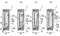
図6中の(a),(b),(c)、(d)は、キャリッジ153が主走査方向に沿って仮想の軌跡上を往復移動するときの移動位置を示す。位置(a)は、キャリッジ153が矢印A1の往方向に移動し始めたときの位置である。位置(b)は矢印A1方向へ移動中であり、位置(c)は、その後にキャリッジ153の移動方向が反転し、それが矢印A2の復方向に移動し始めたときの位置である。位置(d)は、その後にキャリッジ153が矢印A2方向に継続して移動しているときの位置である。このようなキャリッジ153の矢印A1,A2方向の往復運動を利用して、後述するようにインクタンク1内のインク2を攪拌する。
(A), (b), (c), and (d) in FIG. 6 indicate moving positions when the
記録ヘッドは、インクを吐出するためのエネルギとして、電気熱変換体から発生する熱エネルギを利用するものであってもよい。その場合には、電気熱変換体の発熱によってインクに膜沸騰を生じさせ、そのときの発泡エネルギによって、インク吐出口からインクを吐出することができる。また、記録ヘッドにおけるインクの吐出方式は、このような電気熱変換体を用いた方式のみに限定されず、例えば、圧電素子を用いてインクを吐出する方式等であってもよい。 The recording head may use thermal energy generated from the electrothermal transducer as energy for ejecting ink. In that case, film boiling occurs in the ink due to the heat generated by the electrothermal converter, and the ink can be ejected from the ink ejection port by the foaming energy at that time. Further, the ink ejection method in the recording head is not limited to such a method using an electrothermal transducer, and may be a method for ejecting ink using a piezoelectric element, for example.
キャリッジ153の移動領域における図6中の左端には、キャリッジ153に搭載された記録ヘッドのインク吐出口の形成面と対向する回復系ユニット(回復処理手段)158が設けられている。回復系ユニット158には、記録ヘッドのインク吐出口のキャッピングが可能なキャップと、そのキャップ内に負圧を導入可能な吸引ポンプなどが備えられている。そして、インク吐出口を覆ったキャップ内に負圧を導入することにより、インク吐出口からインクを吸引排出させて、記録ヘッドの良好なインク吐出状態を維持するための回復処理を行うことができる。また、キャップ内に向かって、画像の記録に寄与しないインクをインク吐出口から吐出させることによって、記録ヘッドの良好なインク吐出状態を維持する回復処理(予備吐出処理)ともいう)を行うこともできる。
A recovery system unit (recovery processing means) 158 is provided at the left end in FIG. 6 in the movement region of the
(攪拌メカニズム)
図7(a),(b),(c)、(d)は、攪拌部材20Aによるインク2の攪拌動作を説明するための断面図であり、それぞれ、図6中のキャリッジ153の位置(a),(b),(c)、(d)における動作状態を示す。攪拌部材20Bは、この攪拌部材20Aと同様に動作する。
(Stirring mechanism)
FIGS. 7A, 7B, 7C, and 7D are cross-sectional views for explaining the stirring operation of the
まず、図7(a)のように、キャリッジ153が矢印A1方向に移動し始めたときには、インクタンク1内の攪拌部材20Aは、支持部15Aとの接触位置を中心に慣性力によって矢印C1方向に回転し始める。攪拌部材20Aが矢印C1方向に回転し始めることにより、攪拌部材20Aと内壁10Aとの間の空間Sが拡大し、その拡大した空間S内にインクが流れ込み始める。
First, as shown in FIG. 7A, when the
次に、図7(b)のように、さらにキャリッジ153が矢印A1方向に移動すると、攪拌部材20Aの回転の角度(攪拌部材の側面と鉛直方向とのなす角度)は、攪拌部材20Aの凹部21Aと支持部15Aの軸の隙間g(図1参照)の範囲でさらに回転して行く。その結果、攪拌部材20Aと内壁10Aとの間の空間Sはさらに拡大し、その空間Sにインクタンク1の底部付近のインクが矢印D1に示ように流れ込む。図7(b)は、攪拌部材20Aがほぼ最大角度となった状態を示しているが、この状態では、まだキャリッジ153が矢印A1方向へと移動しており、攪拌部材20Aには依然として慣性力が加わっている。この慣性力により、攪拌部材20Aは支持部15Aに沿って矢印C3に示す方向へと移動し始める。そして、キャリッジ15は、図7(c)に示す反転位置の手前で減速しつつ反転位置に達し、その後矢印A2方向へと反転移動を開始する。このとき、空間Sは最大の体積となる。従って、この攪拌部材20のC3方向への移動に伴って、インクはさらに空間S内に流れ込む。
Next, as shown in FIG. 7B, when the
キャリッジ153が反転位置から矢印A2方向へと加速されることにより、それまで矢印C1方向に最大に揺動していた攪拌部材20Aは、矢印C2方向の揺動を開始する。これにより、攪拌部材20Aと内壁10Aとの間の距離が減少し始め、空間S内のインクは攪拌部材20に押圧されて矢印D2のように上方へと流れる。
As the
次に、図7(d)に示ように、キャリッジ153が引き続き矢印A2方向に移動すると、攪拌部材20Aの自由端が内壁14Aに接近し、空間S内のインクは、矢印D3のように攪拌部材20Aの支持部側の間隙に向かって押し出される。このとき、攪拌部材20Aに生じる慣性力よりも、空間Sから押し出されるインクの流抵抗の方が大きい場合には、攪拌部材20Aの揺動速度が大きく低下する。このため、キャリッジ153の加速力、攪拌部材20Aの質量などを調整して、インクの流抵抗よりも攪拌部材20Aの慣性力を大きくすることが好ましい。その後、さらに攪拌部材20Aに慣性力がかかると、矢印C4のように攪拌部材20Aは、支持部15に沿って矢印C4へと移動し、図7(a)に示す状態に戻る。以降、キャリッジ153の往復動作が続く限り、図7(a),(b),(c)、(d)の状態を繰り返す。
Next, as shown in FIG. 7D, when the
以上のように、本例においては、攪拌部材20Aと支持部15との間に摩擦抵抗が発生するため、キャリッジ153が移動を開始すると、先ず、攪拌部材20Aの自由端が先行して移動し、続いて、支持部側端部が移動するという動作を行う。この動作が、ポンプ効果を生み出し、インク収納室Rの下方にあるインクを上方へと循環させることが可能となる。さらに、大きく移動する自由端側が鉛直方向の下側に位置するよう構成してあるため、インク収納室Rの下側に沈降した顔料成分を攪拌することが可能となる。このため、前述のポンプ効果と相俟ってインク収納室Rに収容されたインクに含まれる顔料成分を効率的的に混ぜ合わせることができ、インク濃度の均一化を図ることができる。
As described above, in this example, since frictional resistance is generated between the stirring
すなわち、インクタンク1をキャリッジ153に搭載したまま、記録装置を長期間に亘って放置した場合には、そのインクタンク1内のインクの顔料成分が沈降し、上下方向においてインクタンク1内のインク濃度が異なるような濃度分布が生じる。このようなインクタンク1内のインクに対して、本例では、上記のような上方方向のインク流れを発生させることにより、効率よくインクの攪拌を行うことができる。従って、インク収納室R内のインクを、短時間の攪拌動作で確実に均一濃度にすることができる。
That is, when the recording apparatus is left for a long period of time with the ink tank 1 mounted on the
さらに、本例においては、図1あるいは図4に示すようにインク導出口64をインク収納室R内の最下面から上方位置に配置している。その結果、インク導出口64の直上のインクに含まれる顔料成分の沈降はメニスカス保持部材62あるいは毛管部材61にまで達するが、その他の部分に位置するインクの顔料成分は、インク導出口64内には侵入しない。但し、インクの顔料成分の沈降が進み、濃度の高いインクがインク導入口64の高さ以上に達した場合には、その濃度の高いインクがインク導出口64から侵入する。しかし、このインクは、最も高い濃度を有するインクではなく、図5に示したように、初期濃度から僅かに増加した程度の濃度を有するインクとなる。このため、ある程度の保存期間内においては、インク導出口64から毛管部材61に至る流路内に位置するインクを、記録動作開始前に回復動作によって排出する必要はなく、攪拌動作を行った後、すぐに記録動作を開始することができる。
Further, in this example, as shown in FIG. 1 or FIG. 4, the
また、保存されていたインクタンクの使用開始当初において、インク収納室Rの最下面の近傍には、顔料成分の堆積した濃度の高いインクが存在する。しかし、本例のように、インク導出口64の高さをある程度確保しておけば、保存期間が比較的短い場合、インク導出口64の位置におけるインクの濃度が図5に示すような印字にふさわしい初期濃度になっている場合がある。この場合、記録動作開始前に攪拌を行わなくとも適正な濃度のインクを記録ヘッドに供給することができ、その後に攪拌を行い、インク収容室R内のインクの濃度の均一化を行えば、全てのインクを適正な濃度で使用することができる。
In addition, at the beginning of the use of the stored ink tank, near the lowermost surface of the ink storage chamber R, ink with a high concentration in which pigment components are deposited exists. However, if the height of the
このように、本例によれば、インク導出口64の高さをインク収容室の最下面より高い位置に設定しているため、ユーザが記録装置を起動してから記録動作が開始されるまでの待ち時間を低減することができ、速やかに記録動作を開始することができる。
これに対し、仮に、インク導出口64がインク収納室Rの最下面に配置されている場合には、長期間放置を行うと、沈降してきた顔料成分がインク供給口の毛管部材61へと移動することがある。つまり、毛管部材61に最も濃度の高いインクが滞留することとなる。毛管部材61内部のインクまで攪拌部材20A,20Bによるインクの流れは到達しづらいので、毛管部材61の内部のインクを攪拌できないおそれがある。また、インク導出口64が小さい場合には同様に攪拌部材20A,20Bによるインクの流れがインク導出口64の内部で急激に減衰する。このため、インク導出口64の内部まで攪拌することは困難になる。従って、この場合には、インク導出口64の内部の高濃度のインクを記録ヘッドを通して記録装置の回復装置によって外部に排出する必要がある。また、インク導出口64がインク収納室Rの最下面に位置している場合には、最下面に位置するインクを確実に攪拌してから、記録動作を開始する必要がある。従って、記録装置を起動してから記録動作が開始されるまでに、ユーザは長時間待たされることとなる。
As described above, according to this example, the height of the
On the other hand, if the
ところで圧力板31は、インク収納室R内のインクの消費に伴ってタンクケース10の内側面に接近するため、攪拌部材の20A,20Bの揺動可能範囲が徐々に小さくなる。しかし、本例にあっては、タンクケース10側に掘り込み部14A,14Bが形成されているため、攪拌部材20A,20Bの攪拌機能を最後まで維持することができる。また、掘り込み部14A,14Bを形成することによって、攪拌部材20A,20Bの揺動可能範囲を確保しつつ、インクタンク1の図1中左右方向の幅を小さく設定することができる。この結果、キャリッジ153上に、複数のインクタンク1を矢印Aの主走査方向にコンパクトに並べて配備することができる。
Incidentally, since the
[第2の実施形態]
次に、本発明の第2の実施形態を説明する。
図8は、本発明の第2の実施形態におけるインクタンクの斜視図であり、図9は、図8に示すインクタンクの内部構造を示す斜視図であり、インクケース10に攪拌部材20A、20Bを組付けた状態を示している。
本例の場合、第1の実施形態と内部構造はほぼ同一であるが、供給口60の形成位置が異なる。つまり、図8の矢印Yに示すような方向で記録ヘッド(不図示)に装着される点が異なる。図8および図9から明らかなように、インク供給口60がインク収納室Rに対し鉛直方向(図中のX方向)の下方に存在しないため、毛管部材61やメニスカス保持部材62内にインクの顔料成分が沈降しない。従って、本例によれば1)インク供給口に侵入した濃度の高いインクを外部へ排出すること。2)インク収納室の最下面に位置するインクを確実に攪拌し記録動作を開始すること。という課題を解決することができる。
[Second Embodiment]
Next, a second embodiment of the present invention will be described.
FIG. 8 is a perspective view of an ink tank according to the second embodiment of the present invention. FIG. 9 is a perspective view showing the internal structure of the ink tank shown in FIG. It shows the state assembled.
In this example, the internal structure is substantially the same as that of the first embodiment, but the formation position of the
ところで、本例のインクタンク1においても、記録ヘッド装着前にインク供給口60を下向きにして置いていた場合には、インク供給口60内にインクの顔料成分が堆積することがある。従って、本例のインクタンクは、記録装置への装着状態における顔料成分の沈降に対しては有効であるが、インクタンク装着直後に関しては、従来と同様にインク供給口内に沈降した高い粘度、高濃度のインクを排出することが必要になることもある。
Incidentally, even in the ink tank 1 of this example, when the
しかしながら、本例のインクタンクは、図9に示すように、記録ヘッド装着状態において、インク導出口64、毛管部材61、およびメニスカス保持部材62が、インク収納室R内の最下面より高い位置に配置されている。このため、記録ヘッドにインクタンクを装着した後、インク収納室R内を攪拌している間に、毛管部材61やメニスカス保持部材62内に堆積した顔料成分が、鉛直方向下方にあるインク収納室Rの下面側に移動する。従って、インクタンク装着直後にインク供給口内のインク排出を行う場合にも、そのインクの排出量を低減することができ、ランニングコストを抑えることが可能になる。
However, in the ink tank of this example, as shown in FIG. 9, the
[第3の実施形態]
次に、本発明の第3の実施形態を説明する。
図10は、本発明の第3の実施形態におけるインクタンク1を記録ヘッド80に装着する様子を示す断面斜視図であり、図11は記録ヘッドに装着した状態を示す断面図である。
本例のインクタンク1のインク供給口60は、タンク本体10の底部に形成された貫通孔60Aと、その内面に固定したOリング形状のシールゴム67とにより形成されている。そして、このインク供給口60は、ジョイントバネ65によって付勢されるジョイントボール66によって、常には閉塞された状態に保たれ、インク収納室Rからのインクの垂れ出しを防止するようになっている。
一方、このインクタンク1が装着される記録ヘッド80には、インクタンク1のインク供給口60に対応して管状のニードル(インク導出管)70が突設され、これがインクを吐出するインク吐出部73に連通している。
[Third Embodiment]
Next, a third embodiment of the present invention will be described.
FIG. 10 is a cross-sectional perspective view showing a state in which the ink tank 1 according to the third embodiment of the present invention is attached to the
The
On the other hand, the
上記インクタンク1の記録ヘッド80への装着は、シールゴム67の挿通孔67内にニードル70を挿通させることによって行う。このとき、記録ヘッド80のニードル70は、ジョイントボール66をジョイントバネ65の付勢力に抗して押し上げる。またニードル70は、シールゴム67の挿通孔67の内面に液密に接触するため、シールゴム67からインクが漏れることはない。ニードル70の上端部付近には、開口部71が形成されており、インク収容室R内のインクは、この開口部71からニードル70内に流入し、ヘッドフィルタ72を介してインク吐出部73へと供給される。このインクタンク装着時において、ニードル70の開口部71は、インク収容室R内の最下面より鉛直方向上方に位置する。このため、本例によれば、インク収容室R内の最下面にインクの顔料成分が沈降している場合にも、ニードル70の開口部71に高粘度および高濃度のインクが流入することはない。従って、本例によれば、上記の他の実施形態と同様に、前述の2つの課題を解消することができる。すなわち、本例によれば、インク供給口に侵入したインクを外部へ排出させる必要がなくなると共に、インク収納室の最下面に位置するインクまで確実に攪拌しなくとも、記録動作を開始することが可能になる。
The ink tank 1 is attached to the
[第4の実施形態]
次に、本発明の第4の実施形態を説明する。
図12は、本発明の第4の実施形態におけるインクタンク1の断面図である。
本例のインクタンクでは、導出口形成壁68A,68Bによって、左右両側方に向けて開口する2個のインク導出口64A,64Bが形成されている。導出口側壁68Aは、インク供給口の開口部端縁によって囲まれる面(以下、開口面と称す)と略平行に対向する位置に配置されている。また、導出口側壁68Bはインク供給口の開口面と直交する方向に突出しており、この導出口側壁68Bと、68Aとによってインク導出口64A,64Bが形成されている。このインク導出口64A,64Bは、上記第1および第2の実施形態と同様に、インク収納室Rの最下面より上方に位置している。このため、インク収容室の底部に沈降した顔料成分によって高粘度化および高濃度化したインクが、インク供給口へと侵入するのを抑制することができる。
[Fourth Embodiment]
Next, a fourth embodiment of the present invention will be described.
FIG. 12 is a cross-sectional view of the ink tank 1 according to the fourth embodiment of the present invention.
In the ink tank of this example, two
また、本例においては、インク導出口64A,64Bの向きが、インク供給口60の向きに対して直交するように形成されていることから、上記第1および第2の実施形態に比し、さらに次のような効果が期待できる。
In this example, the direction of the
すなわち、上記第1の実施形態のように、インク導出口がインク供給口の上方に位置し、かつそれらの向きが同一であると、インク導出口上部のインクの顔料成分はそのままインク供給口部に沈降する。これに対し本例においては、各インク導出口69A,69Bを形成する導出口側壁68Aによって、インク供給口上のインクに含まれる顔料成分がインク供給口部に直接沈降するのを抑制することができる。
That is, as in the first embodiment, when the ink outlet port is located above the ink supply port and the directions thereof are the same, the pigment component of the ink above the ink outlet port remains as it is. To settle. On the other hand, in this example, it is possible to suppress the pigment component contained in the ink on the ink supply port from directly sinking to the ink supply port portion by the discharge
また、第1の実施形態のように、インク導出口64がインク供給口60の上方に位置し、向きが同一であると、インク供給口60を下向きにした状態でインクタンク1が落下したり、強く振られたりした場合に、インク供給口60からインクが垂れる場合がある。これは、落下や手振りなどの動作によってインクに働く慣性力が直接インク供給口60に向かうため、メニスカス保持部材62や毛管部材61に生じる抵抗では、インクに働く慣性力を減衰し切れないためである。このような現象に対し、本例では、インク導出口64からインク供給口に至るインク導出流路が、図12の矢印に示ように屈曲するよう形成されており、インクの慣性力がインク導出口側壁によって分散されるようになっている。このため、大きな慣性力がインク供給口に直接的に到達することがない。さらに、インク導出口64A,64Bからインク供給口60に至る流路の間には、複数の連通口(ここでは、3つの連通口69A,69B、69C)が形成され、前記流路内におけるインクの流抵抗を増大させる構造となっている。この構造によれば、インク慣性力がインク導出口内に達した場合にも、その慣性力を各連通口に生じるインクの流抵抗によって減衰させることができる。従って、上記構成によれば、落下や手振りによるインクの垂れ出しを抑制することが可能になる。
Further, as in the first embodiment, when the
[第5の実施形態]
次に、本発明の第5の実施形態を説明する。
図13は、本発明の第5の実施形態におけるインクタンク1の断面図である。
本例におけるインクタンク1は、上記第1の実施形態におけるインクタンク1と同様に、インク導出口64A,64Bがインク収納室Rの最下面より上方に位置し、沈降した顔料インクのインク供給口への侵入を抑制している。また、本構成においても、インク導出口64の向きが、インク供給口に対し、異なった方向となっているため、落下や手振りに対するインクたれとしてもより好ましい構成となっている。
[Fifth Embodiment]
Next, a fifth embodiment of the present invention will be described.
FIG. 13 is a cross-sectional view of the ink tank 1 according to the fifth embodiment of the present invention.
In the ink tank 1 in this example, as with the ink tank 1 in the first embodiment, the
[その他の実施形態]
上記実施形態では、インクタンクのインク収容室内に顔料インクを収容した場合を例に採り説明したが、本発明は、顔料インクだけでなく、染料インクを収容したインクタンクにおいても有効である。すなわち、染料インクにあっても長期の保存などによっては、染料粒子が沈降することがあり、このような場合にも本発明におけるインクタンクは、有効である。
[Other Embodiments]
In the above embodiment, the case where the pigment ink is stored in the ink storage chamber of the ink tank has been described as an example, but the present invention is effective not only in the pigment ink but also in the ink tank storing the dye ink. That is, even in the case of dye ink, dye particles may settle depending on long-term storage and the like, and in such a case, the ink tank in the present invention is effective.
以上のように、上記各実施形態では、インクタンクのインク収納室内に沈降した顔料成分を含む高粘度、高濃度のインクが、インク供給口や記録ヘッドへと侵入するのを抑制する構成を備えるものとなっている。しかし、物流状態においてはインクタンクの姿勢が様々に変化する可能性があり、僅かながら高粘度、高濃度のインクがインク供給口に侵入する可能性もある。従って、インク供給口に高粘度、高濃度のインクが侵入した場合には、そのインクを吸引ポンプにより効率よく排出する必要がある。従って、インク導出口からインク供給口に至る流路において、吸引時によどみが生じるような、急激な流路断面の形状または面積が変化する部分がある場合には、その部分のインクを排出するためにインク排出量を増大させる必要がある。従って、本構成のように、インク導出口からインク供給口にかけての流路の断面形状および面積を滑らかに変化させることにより、吸引排出におけるよどみ部をなくすことが望ましく、これによって、効率よく流路内のインクを吸引排出させることができる。 As described above, each of the above-described embodiments includes a configuration that prevents high-viscosity, high-concentration ink containing a pigment component that has settled in the ink storage chamber of the ink tank from entering the ink supply port and the recording head. It has become a thing. However, in the physical distribution state, the posture of the ink tank may change variously, and there is a possibility that slightly high-viscosity and high-density ink may enter the ink supply port. Therefore, when high-viscosity and high-density ink enters the ink supply port, it is necessary to efficiently discharge the ink with a suction pump. Therefore, if there is a portion where the shape or area of the abrupt flow passage cross section changes in the flow passage from the ink outlet to the ink supply port, such that stagnation occurs during suction, the ink in that portion is discharged. In addition, it is necessary to increase the ink discharge amount. Therefore, as in this configuration, it is desirable to eliminate the stagnation part in the suction and discharge by smoothly changing the cross-sectional shape and area of the flow path from the ink outlet port to the ink supply port. The ink inside can be sucked and discharged.
1 インクタンク
2 インク
10 タンクケース
10A 内壁
14A,14B 掘り込み部
15,16 支持部
15A,16A 軸部
15B,16B 抜け止め部
20A,20B 攪拌部材
30 ばね部材
31 圧力板
40 可撓性部材
60 インク供給口
61 毛管部材
62 メニスカス保持部材
63 供給口部材
64 インク導出口
65 ジョイントバネ
66 ジョイントボール
67 シールゴム
68A,68B 導出口側壁
69A,69B,69C 連通口
70 ニードル
71 開口部
72 ヘッドフィルタ
73 インク吐出部
80 記録ヘッド
150 記録装置
153 キャリッジ
DESCRIPTION OF SYMBOLS 1
Claims (8)
インクを収納するインク収納室と、
前記インク収納室の内壁に備えられ、前記インク収納室の内部に突出する突出部材と、
該突出部材に係合される係合部を有する攪拌部材と、
前記インク収納室の内部に設けられるインク導出口と、
前記インクタンクの外側に設けられるインク供給口と、
前記インク導出口と前記インク供給口とをつなぎ、前記インク収納室内のインクを前記インクタンク外へ供給する際の流路となるインク導出流路と、
を備え、
前記インク導出口は、前記インクタンクが前記プリンタに装着される姿勢において、前記インク収納室の内壁の最下面より上方に配され、
前記攪拌部材は前記係合部を回動軸として回動し、かつ、前記突出部材が突出する方向に沿って前記係合部は移動することを特徴とするインクタンク。 An ink tank attached to the printer,
An ink storage chamber for storing ink;
A protruding member provided on an inner wall of the ink storage chamber and protruding into the ink storage chamber;
A stirring member having an engaging portion engaged with the protruding member;
An ink outlet provided in the ink storage chamber;
An ink supply port provided outside the ink tank;
An ink outlet channel connecting the ink outlet port and the ink supply port, and serving as a channel when the ink in the ink storage chamber is supplied to the outside of the ink tank ;
With
The ink outlet is disposed above the lowermost surface of the inner wall of the ink storage chamber in a posture in which the ink tank is attached to the printer.
An ink tank wherein the agitating member is rotated the engagement portion as a rotation axis, and the engagement portion along the direction in which the protruding member protrudes is characterized that you move.
前記攪拌部材は自由端を有し、
前記インク導出口は、前記インクタンクが前記キャリッジに搭載される姿勢において、
前記攪拌部材の前記自由端より下側に設けられ、
前記キャリッジの往復移動に伴って前記攪拌部材は可動することを特徴とする請求項1に記載のインクタンク。 The ink tank is mounted on a carriage of a reciprocating printer,
The stirring member has a free end;
The ink outlet port is in a posture in which the ink tank is mounted on the carriage.
Provided below the free end of the stirring member;
The ink tank according to claim 1, wherein the agitating member is moved as the carriage is reciprocated.
前記攪拌部材は板状の部材で、前記第1の内壁に面して配置されることを特徴とする請求項2に記載のインクタンク。 The ink storage chamber has a first inner wall that intersects the reciprocating direction in a state where the ink tank is mounted on the carriage.
The ink tank according to claim 2 , wherein the stirring member is a plate-like member and is disposed to face the first inner wall.
前記攪拌部材が回動をはじめた後に、前記係合部の移動が行われることを特徴とする請求項2または3に記載のインクタンク。 The protruding member protrudes along a direction in which the carriage reciprocates;
The ink tank according to claim 2 , wherein the engagement portion is moved after the stirring member starts rotating.
前記インクタンクは、
インクを収納するインク収納室と、
記インク収納室の内壁に備えられ、前記インク収納室の内部に突出する突出部材と、
該突出部材に係合される係合部を有する攪拌部材と、
前記インク収納室の内部に設けられるインク導出口と、
前記インクタンクの外側に設けられるインク供給口と、
前記インク導出口と前記インク供給口とをつなぎ、前記インク収納室内のインクを前記インクタンク外へ供給する際の流路となるインク導出流路と、
を備え、
前記インク導出口は、前記インクタンクが前記キャリッジに搭載される姿勢において、前記インク収納室の内壁の最下面より上方に配され、
前記キャリッジの往復移動に伴って、前記攪拌部材は前記係合部を回動軸として回動し、かつ、前記突出部材が突出する方向に沿って前記係合部は移動することを特徴とするプリンタ。 In a printer having an ink tank that stores pigment ink containing a pigment component used for printing and a carriage that reciprocates by mounting a head that discharges the liquid,
The ink tank is
An ink storage chamber for storing ink;
A protrusion member provided on the inner wall of the ink storage chamber and protruding into the ink storage chamber;
A stirring member having an engaging portion engaged with the protruding member;
An ink outlet provided in the ink storage chamber;
An ink supply port provided outside the ink tank;
An ink outlet channel connecting the ink outlet port and the ink supply port, and serving as a channel when the ink in the ink storage chamber is supplied to the outside of the ink tank ;
With
The ink outlet is disposed above the lowermost surface of the inner wall of the ink storage chamber in a posture in which the ink tank is mounted on the carriage.
As the carriage reciprocates, the stirring member rotates about the engaging portion as a rotation shaft, and the engaging portion moves along a direction in which the protruding member protrudes. Printer.
Priority Applications (1)
| Application Number | Priority Date | Filing Date | Title |
|---|---|---|---|
| JP2006058378A JP4916190B2 (en) | 2006-03-03 | 2006-03-03 | Ink tank and printer |
Applications Claiming Priority (1)
| Application Number | Priority Date | Filing Date | Title |
|---|---|---|---|
| JP2006058378A JP4916190B2 (en) | 2006-03-03 | 2006-03-03 | Ink tank and printer |
Publications (3)
| Publication Number | Publication Date |
|---|---|
| JP2007230189A JP2007230189A (en) | 2007-09-13 |
| JP2007230189A5 JP2007230189A5 (en) | 2011-01-20 |
| JP4916190B2 true JP4916190B2 (en) | 2012-04-11 |
Family
ID=38551244
Family Applications (1)
| Application Number | Title | Priority Date | Filing Date |
|---|---|---|---|
| JP2006058378A Expired - Fee Related JP4916190B2 (en) | 2006-03-03 | 2006-03-03 | Ink tank and printer |
Country Status (1)
| Country | Link |
|---|---|
| JP (1) | JP4916190B2 (en) |
Families Citing this family (9)
| Publication number | Priority date | Publication date | Assignee | Title |
|---|---|---|---|---|
| JP5550220B2 (en) * | 2008-08-29 | 2014-07-16 | キヤノン株式会社 | Ink tank |
| JP2011194584A (en) | 2010-03-17 | 2011-10-06 | Seiko Epson Corp | Liquid container and liquid ejecting apparatus |
| JP5678500B2 (en) * | 2010-07-20 | 2015-03-04 | セイコーエプソン株式会社 | Liquid container and liquid ejecting apparatus |
| US8491107B2 (en) | 2010-10-29 | 2013-07-23 | Funai Electric Co., Ltd. | Fluid container having mixing chambers for micro-fluid applications |
| US8752941B2 (en) * | 2010-11-17 | 2014-06-17 | Funai Electric Company Ltd. | Fluid container having latching interface for micro-fluid applications |
| CN102815093B (en) * | 2010-10-29 | 2016-01-27 | 船井电机株式会社 | A kind of consumptive material delivery member |
| JP5776196B2 (en) * | 2011-02-04 | 2015-09-09 | セイコーエプソン株式会社 | Liquid container to be mounted on liquid ejecting apparatus |
| US8590756B2 (en) | 2011-04-26 | 2013-11-26 | Funai Electric Co., Ltd. | Container with tube drawing desired fluid concentrations for micro-fluid applications |
| JP5550711B2 (en) * | 2012-12-21 | 2014-07-16 | キヤノン株式会社 | Ink tank |
Family Cites Families (6)
| Publication number | Priority date | Publication date | Assignee | Title |
|---|---|---|---|---|
| JP3127581B2 (en) * | 1992-06-26 | 2001-01-29 | セイコーエプソン株式会社 | Ink jet recording apparatus and operation method |
| JP2002144598A (en) * | 2000-11-13 | 2002-05-21 | Oki Data Corp | Liquid storage container |
| JP2004216761A (en) * | 2003-01-16 | 2004-08-05 | Seiko Epson Corp | Ink tank and inkjet printer |
| JP2005066520A (en) * | 2003-08-26 | 2005-03-17 | Seiko Epson Corp | Liquid housing body, liquid tank, liquid stirrer and liquid injector |
| JP4552526B2 (en) * | 2004-06-16 | 2010-09-29 | セイコーエプソン株式会社 | Liquid container |
| JP2006044153A (en) * | 2004-08-06 | 2006-02-16 | Seiko Epson Corp | Liquid storing body and liquid injection device |
-
2006
- 2006-03-03 JP JP2006058378A patent/JP4916190B2/en not_active Expired - Fee Related
Also Published As
| Publication number | Publication date |
|---|---|
| JP2007230189A (en) | 2007-09-13 |
Similar Documents
| Publication | Publication Date | Title |
|---|---|---|
| JP5550220B2 (en) | Ink tank | |
| JP4916190B2 (en) | Ink tank and printer | |
| JP4646745B2 (en) | Ink tank | |
| JP4235633B2 (en) | Ink tank and recording device | |
| AU2003264950B2 (en) | Liquid supply system, fluid communicating structure, ink supply system, and inkjet recording head utilizing the fluid communicating structure | |
| US7735984B2 (en) | Liquid container | |
| JP3697213B2 (en) | Liquid storage container and liquid stirring method | |
| EP0683050B1 (en) | Ink supplying apparatus and ink jet recording apparatus having same | |
| JP4047259B2 (en) | Ink supply system | |
| EP3184310B1 (en) | Liquid container member | |
| JP2008273045A (en) | Liquid storage container, liquid stirring apparatus, and recording device | |
| JP2010120294A (en) | Liquid jet apparatus | |
| JP2004142447A (en) | Liquid supply system, fluid connection structure, ink supply system, and ink jet recording head and recorder employing fluid connection structure | |
| US20070052768A1 (en) | Liquid Container | |
| JP5550711B2 (en) | Ink tank | |
| JP2007223159A (en) | Ink storing container and ink supplying system using same | |
| JP5617215B2 (en) | Liquid ejecting apparatus, liquid container | |
| JP2008273043A (en) | Liquid storage container, head cartridge, and ink-jet recording device | |
| JP2008273040A (en) | Liquid container | |
| JP2004122499A (en) | Liquid tank, liquid communication structure, liquid supply system, and ink jet recorder | |
| JP2008273046A (en) | Liquid container and inkjet recorder | |
| JP2009262496A (en) | Waste liquid receiving container | |
| JP2004306393A (en) | Liquid conduction structure interconnecting liquid containing section and liquid using section | |
| JP2004351865A (en) | Inkjet storage device | |
| JP2011167911A (en) | Liquid jet system, liquid injector, and liquid housing container |
Legal Events
| Date | Code | Title | Description |
|---|---|---|---|
| A621 | Written request for application examination |
Free format text: JAPANESE INTERMEDIATE CODE: A621 Effective date: 20090303 |
|
| RD02 | Notification of acceptance of power of attorney |
Free format text: JAPANESE INTERMEDIATE CODE: A7422 Effective date: 20101106 |
|
| A521 | Request for written amendment filed |
Free format text: JAPANESE INTERMEDIATE CODE: A523 Effective date: 20101129 |
|
| A977 | Report on retrieval |
Free format text: JAPANESE INTERMEDIATE CODE: A971007 Effective date: 20110411 |
|
| A131 | Notification of reasons for refusal |
Free format text: JAPANESE INTERMEDIATE CODE: A131 Effective date: 20110415 |
|
| A521 | Request for written amendment filed |
Free format text: JAPANESE INTERMEDIATE CODE: A523 Effective date: 20110614 |
|
| TRDD | Decision of grant or rejection written | ||
| A01 | Written decision to grant a patent or to grant a registration (utility model) |
Free format text: JAPANESE INTERMEDIATE CODE: A01 Effective date: 20120120 |
|
| A01 | Written decision to grant a patent or to grant a registration (utility model) |
Free format text: JAPANESE INTERMEDIATE CODE: A01 |
|
| A61 | First payment of annual fees (during grant procedure) |
Free format text: JAPANESE INTERMEDIATE CODE: A61 Effective date: 20120124 |
|
| FPAY | Renewal fee payment (event date is renewal date of database) |
Free format text: PAYMENT UNTIL: 20150203 Year of fee payment: 3 |
|
| R151 | Written notification of patent or utility model registration |
Ref document number: 4916190 Country of ref document: JP Free format text: JAPANESE INTERMEDIATE CODE: R151 |
|
| FPAY | Renewal fee payment (event date is renewal date of database) |
Free format text: PAYMENT UNTIL: 20150203 Year of fee payment: 3 |
|
| LAPS | Cancellation because of no payment of annual fees |