JP2012024928A - Fluid ejection device, cleaning method in fluid ejection device and program - Google Patents
Fluid ejection device, cleaning method in fluid ejection device and program Download PDFInfo
- Publication number
- JP2012024928A JP2012024928A JP2010162535A JP2010162535A JP2012024928A JP 2012024928 A JP2012024928 A JP 2012024928A JP 2010162535 A JP2010162535 A JP 2010162535A JP 2010162535 A JP2010162535 A JP 2010162535A JP 2012024928 A JP2012024928 A JP 2012024928A
- Authority
- JP
- Japan
- Prior art keywords
- nozzle
- cleaning
- fluid
- inspection
- ink
- Prior art date
- Legal status (The legal status is an assumption and is not a legal conclusion. Google has not performed a legal analysis and makes no representation as to the accuracy of the status listed.)
- Withdrawn
Links
- 238000004140 cleaning Methods 0.000 title claims abstract description 183
- 239000012530 fluid Substances 0.000 title claims abstract description 112
- 238000000034 method Methods 0.000 title claims abstract description 54
- 238000007689 inspection Methods 0.000 claims abstract description 170
- 230000002950 deficient Effects 0.000 claims abstract description 36
- 238000002347 injection Methods 0.000 claims description 19
- 239000007924 injection Substances 0.000 claims description 19
- 238000003825 pressing Methods 0.000 claims description 6
- 238000007599 discharging Methods 0.000 claims description 3
- 238000012360 testing method Methods 0.000 claims description 2
- 238000012423 maintenance Methods 0.000 abstract description 23
- 239000000976 ink Substances 0.000 description 144
- 230000008569 process Effects 0.000 description 45
- 239000007788 liquid Substances 0.000 description 26
- 238000001514 detection method Methods 0.000 description 16
- 238000012545 processing Methods 0.000 description 14
- 238000003860 storage Methods 0.000 description 12
- 230000032258 transport Effects 0.000 description 7
- 238000011010 flushing procedure Methods 0.000 description 6
- 230000001965 increasing effect Effects 0.000 description 6
- 239000000463 material Substances 0.000 description 6
- 230000015572 biosynthetic process Effects 0.000 description 5
- 230000007547 defect Effects 0.000 description 5
- 238000006243 chemical reaction Methods 0.000 description 4
- 239000000049 pigment Substances 0.000 description 4
- 239000011358 absorbing material Substances 0.000 description 3
- 230000008859 change Effects 0.000 description 3
- 238000010586 diagram Methods 0.000 description 3
- 230000000694 effects Effects 0.000 description 3
- 239000004973 liquid crystal related substance Substances 0.000 description 3
- 239000002184 metal Substances 0.000 description 3
- 239000011347 resin Substances 0.000 description 3
- 229920005989 resin Polymers 0.000 description 3
- 230000005540 biological transmission Effects 0.000 description 2
- 238000004891 communication Methods 0.000 description 2
- 230000007423 decrease Effects 0.000 description 2
- 230000006698 induction Effects 0.000 description 2
- 238000004519 manufacturing process Methods 0.000 description 2
- 230000007246 mechanism Effects 0.000 description 2
- 230000003287 optical effect Effects 0.000 description 2
- 239000000243 solution Substances 0.000 description 2
- 239000002904 solvent Substances 0.000 description 2
- 239000000126 substance Substances 0.000 description 2
- 239000000758 substrate Substances 0.000 description 2
- 238000011144 upstream manufacturing Methods 0.000 description 2
- 239000002699 waste material Substances 0.000 description 2
- XLYOFNOQVPJJNP-UHFFFAOYSA-N water Substances O XLYOFNOQVPJJNP-UHFFFAOYSA-N 0.000 description 2
- 238000000018 DNA microarray Methods 0.000 description 1
- 239000002253 acid Substances 0.000 description 1
- 239000003513 alkali Substances 0.000 description 1
- 230000003321 amplification Effects 0.000 description 1
- 238000013459 approach Methods 0.000 description 1
- 230000008901 benefit Effects 0.000 description 1
- 230000004397 blinking Effects 0.000 description 1
- 239000003086 colorant Substances 0.000 description 1
- 238000001035 drying Methods 0.000 description 1
- 239000007772 electrode material Substances 0.000 description 1
- 238000005401 electroluminescence Methods 0.000 description 1
- 230000003028 elevating effect Effects 0.000 description 1
- 238000005530 etching Methods 0.000 description 1
- 239000004744 fabric Substances 0.000 description 1
- 239000011888 foil Substances 0.000 description 1
- 230000006870 function Effects 0.000 description 1
- 239000008187 granular material Substances 0.000 description 1
- 230000005484 gravity Effects 0.000 description 1
- 239000012943 hotmelt Substances 0.000 description 1
- 229910001867 inorganic solvent Inorganic materials 0.000 description 1
- 239000003049 inorganic solvent Substances 0.000 description 1
- 230000010354 integration Effects 0.000 description 1
- 239000007791 liquid phase Substances 0.000 description 1
- 229910001338 liquidmetal Inorganic materials 0.000 description 1
- 239000000314 lubricant Substances 0.000 description 1
- 239000008204 material by function Substances 0.000 description 1
- 230000005499 meniscus Effects 0.000 description 1
- 239000002923 metal particle Substances 0.000 description 1
- 238000002156 mixing Methods 0.000 description 1
- 239000000203 mixture Substances 0.000 description 1
- 230000004048 modification Effects 0.000 description 1
- 238000012986 modification Methods 0.000 description 1
- 238000003199 nucleic acid amplification method Methods 0.000 description 1
- 239000011368 organic material Substances 0.000 description 1
- 239000003960 organic solvent Substances 0.000 description 1
- 239000002245 particle Substances 0.000 description 1
- 239000002985 plastic film Substances 0.000 description 1
- 229920006255 plastic film Polymers 0.000 description 1
- -1 plate Substances 0.000 description 1
- 239000011343 solid material Substances 0.000 description 1
- 239000004753 textile Substances 0.000 description 1
- 230000008719 thickening Effects 0.000 description 1
- 230000001960 triggered effect Effects 0.000 description 1
Images

Landscapes
- Coating Apparatus (AREA)
- Ink Jet (AREA)
Abstract
【課題】効率よくクリーニングを実行することができる流体噴射装置、流体噴射装置にお
けるクリーニング方法及びプログラムを提供する。
【解決手段】プリンター11は、インクを噴射するノズルを有する印刷ヘッド42と、不
良ノズルの有無を検査するノズル検査装置64と、吸引クリーニングを行うメンテナンス
装置24と、ノズル検査装置64によるノズル検査の実行頻度に応じて、クリーニング条
件を設定するコントローラー86と、を備える。そして、コントローラー86は、ノズル
検査によって不良ノズルが検出された場合に、設定されたクリーニング条件に基づきメン
テナンス装置24を制御する。
【選択図】図6Provided are a fluid ejecting apparatus capable of efficiently performing cleaning, a cleaning method in the fluid ejecting apparatus, and a program.
A printer 11 includes a print head 42 having nozzles that eject ink, a nozzle inspection device 64 that inspects for the presence of a defective nozzle, a maintenance device 24 that performs suction cleaning, and nozzle inspection performed by the nozzle inspection device 64. And a controller 86 for setting cleaning conditions according to the execution frequency. The controller 86 controls the maintenance device 24 based on the set cleaning condition when a defective nozzle is detected by the nozzle inspection.
[Selection] Figure 6
Description
本発明は、流体を噴射するノズルを有する流体噴射装置、流体噴射装置におけるクリー
ニング方法及びプログラムに関する。
The present invention relates to a fluid ejecting apparatus having a nozzle for ejecting fluid, a cleaning method in the fluid ejecting apparatus, and a program.
一般に、流体噴射装置の一例として、ノズルから流体としてのインクを噴射することで
印刷媒体に印刷を施すインクジェット式プリンターが広く知られている。また、こうした
プリンターのうちには、適切な量のインクが噴射されない不良ノズルの有無を検査するノ
ズル検査を行うものがあった(特許文献1参照)。
In general, as an example of a fluid ejecting apparatus, an ink jet printer that performs printing on a print medium by ejecting ink as a fluid from a nozzle is widely known. Some of these printers perform nozzle inspection for inspecting the presence or absence of defective nozzles that do not eject an appropriate amount of ink (see Patent Document 1).
そして、特許文献1のインクジェット式プリンターは、印刷処理に対する印刷品質レベ
ルが高く設定されている場合には頻繁にノズル検査が実行されるように、ノズル検査の実
行タイミングを設定していた。
And the inkjet type printer of
ところで、特許文献1では、ノズル検査で不良ノズルが検出された場合には、まず吸引
力の小さい弱クリーニングを行い、それでも噴射不良が解消されない場合には、吸引力の
大きい強クリーニングを行うようにしていた。そのため、重度の噴射不良が生じている場
合には何度もクリーニングを行うことになり、クリーニングが終了するまでに時間がかか
っていた。また、重度の噴射不良は弱クリーニングでは解消できないにもかかわらず、弱
クリーニングから順次行うことになるため、無駄にインクが消費されてしまうという問題
があった。
By the way, in
本発明は、上記課題を解決するためになされたものであり、その目的は、効率よくクリ
ーニングを実行することができる流体噴射装置、流体噴射装置におけるクリーニング方法
及びプログラムを提供することにある。
SUMMARY An advantage of some aspects of the invention is to provide a fluid ejecting apparatus, a cleaning method in the fluid ejecting apparatus, and a program capable of efficiently performing cleaning.
上記目的を達成するために、本発明の流体噴射装置は、流体を噴射するノズルを有する
流体噴射手段と、該流体噴射手段における流体噴射不良のノズルの有無を検査するノズル
検査を行うノズル検査手段と、圧力の付与によって前記ノズルから流体を排出させるクリ
ーニングを行うクリーニング手段と、前記ノズル検査手段によるノズル検査の実行頻度に
応じて、クリーニングの条件を設定するクリーニング条件設定手段と、前記ノズル検査に
よって流体噴射不良のノズルが検出された場合に、前記クリーニング条件設定手段によっ
て設定されたクリーニングの条件に基づき前記クリーニング手段を制御する制御手段と、
を備える。
In order to achieve the above object, a fluid ejecting apparatus according to the present invention includes a fluid ejecting unit having a nozzle for ejecting a fluid, and a nozzle inspecting unit for inspecting whether or not there is a fluid ejection defective nozzle in the fluid ejecting unit. A cleaning unit that performs cleaning to discharge the fluid from the nozzle by applying pressure, a cleaning condition setting unit that sets a cleaning condition according to the frequency of nozzle inspection performed by the nozzle inspection unit, and the nozzle inspection. Control means for controlling the cleaning means based on a cleaning condition set by the cleaning condition setting means when a nozzle with poor fluid ejection is detected;
Is provided.
この構成によれば、ノズル検査の実行頻度に関係なくクリーニング条件が設定される場
合と比較して、適切にクリーニング条件を設定することができる。例えば、ノズルの流体
噴射不良は、発生してからの経過時間が長くなると不良の度合いが増し、圧力の強いクリ
ーニングでなければ不良を解消できないことがある。そのため、実行頻度に関係なく圧力
の弱いクリーニングを行うと、その後に圧力の強いクリーニングを追加的に行うことにな
り、最初のクリーニングの分、時間や流体を無駄に消費してしまうおそれがある。一方、
ノズル検査の実行頻度が高ければ、不良の度合いが低いうちに検出を行うことができるの
に、実行頻度に関係なく圧力の強いクリーニングを行うと、流体が無駄に消費されるおそ
れがある。したがって、ノズル検査の実行頻度に応じてクリーニングの条件を設定するこ
とで、無駄に消費される時間や流体の量を低減し、効率よくクリーニングを実行すること
ができる。
According to this configuration, it is possible to appropriately set the cleaning condition as compared with the case where the cleaning condition is set regardless of the execution frequency of the nozzle inspection. For example, the failure of nozzle ejection may increase as the elapsed time from the occurrence of the failure increases, and the failure may not be resolved unless cleaning is performed with a strong pressure. For this reason, if a cleaning with a low pressure is performed regardless of the execution frequency, a cleaning with a high pressure is additionally performed after that, and time and fluid may be wasted for the first cleaning. on the other hand,
If the frequency of nozzle inspection is high, detection can be performed while the degree of failure is low. However, if cleaning is performed with a high pressure regardless of the frequency of execution, the fluid may be wasted. Therefore, by setting the cleaning conditions according to the execution frequency of the nozzle inspection, it is possible to reduce wasteful time and the amount of fluid and perform cleaning efficiently.
本発明の流体噴射装置において、前記クリーニング条件設定手段は、前記ノズル検査の
実行頻度が低いほど、前記ノズル検査によって検出された前記流体噴射不良のノズルに作
用する吸引力が大きくなるように、クリーニングの条件を設定する。
In the fluid ejecting apparatus according to the aspect of the invention, the cleaning condition setting unit may perform cleaning so that the lower the execution frequency of the nozzle inspection, the greater the suction force acting on the nozzle with poor fluid ejection detected by the nozzle inspection. Set the conditions.
この構成によれば、ノズル検査の実行頻度が低いときには吸引力が大きくなるようにク
リーニングの条件が設定されるので、検出された時点での流体噴射不良の度合いが高い場
合にも、吸引力の大きい1回のクリーニングで流体噴射不良を解消することが可能になる
。また、ノズル検査の実行頻度が高いときには吸引力が小さくなるようにクリーニングの
条件が設定されるが、このときには検出された時点での流体噴射不良の度合いが低い可能
性が高いので、吸引力の小さいクリーニングでも流体噴射不良を解消することができる。
したがって、吸引力の小さいクリーニングを無駄に実行したり、過度に大きい吸引力のク
リーニングを実行したりすることなく、少ないクリーニングの実行回数で流体噴射不良を
解消すると共に、吸引クリーニングに伴う流体の消費量を少なくすることができる。
According to this configuration, since the cleaning condition is set so that the suction force is increased when the frequency of nozzle inspection is low, the suction force can be reduced even when the degree of fluid ejection failure at the time of detection is high. It becomes possible to eliminate the fluid ejection failure by one large cleaning. In addition, the cleaning conditions are set so that the suction force is reduced when the frequency of nozzle inspection is high. At this time, it is highly possible that the degree of fluid ejection failure is low. Even a small cleaning can eliminate the fluid ejection failure.
Therefore, it is possible to eliminate fluid ejection defects with a small number of cleanings without wastefully performing cleaning with a low suction force or performing cleaning with an excessively large suction force, and to consume fluid associated with suction cleaning. The amount can be reduced.
本発明の流体噴射装置は、前記流体噴射手段からの流体の噴射量を取得する噴射量取得
手段と、前記噴射量取得手段によって取得された流体の噴射量が多いほど、前記ノズル検
査の実行頻度を高く設定する検査頻度設定手段と、をさらに備え、前記制御手段は、前記
検査頻度設定手段によって設定された実行頻度に基づき前記ノズル検査手段を制御する。
The fluid ejection device according to the present invention includes: an ejection amount acquisition unit that acquires an ejection amount of the fluid from the fluid ejection unit; and the greater the ejection amount of the fluid acquired by the ejection amount acquisition unit, the more frequently the nozzle inspection is performed. And an inspection frequency setting means for setting the nozzle to be high, and the control means controls the nozzle inspection means based on the execution frequency set by the inspection frequency setting means.
この構成によれば、流体の噴射量が多いほどノズル検査の実行頻度が高く設定されるの
で、流体の噴射量が増してノズル内への気泡の混入などによって流体噴射不良が発生する
確率が高くなるタイミングで、ノズル検査を実行することができる。
According to this configuration, since the frequency of nozzle inspection is set higher as the fluid ejection amount is larger, the probability that a fluid ejection failure will occur due to an increase in the fluid ejection amount and the inclusion of bubbles in the nozzle is high. The nozzle inspection can be executed at the following timing.
本発明の流体噴射装置において、前記流体噴射手段は、少なくとも一つの前記ノズルに
よって構成されるノズル群を複数有し、前記噴射量取得手段は前記ノズル群毎に流体の噴
射量を取得すると共に、前記検査頻度設定手段は前記ノズル群毎に前記ノズル検査の実行
頻度を設定する。
In the fluid ejecting apparatus according to the aspect of the invention, the fluid ejecting unit includes a plurality of nozzle groups each including at least one nozzle, and the ejection amount obtaining unit obtains a fluid ejection amount for each nozzle group, The inspection frequency setting means sets the execution frequency of the nozzle inspection for each nozzle group.
この構成によれば、ノズル群毎に流体の噴射量が異なる場合にも、ノズル群毎に適切な
タイミングでノズル検査を行うことができる。
上記目的を達成するために、本発明の流体噴射装置におけるクリーニング方法は、流体
を噴射するノズルを有する流体噴射手段を備えた流体噴射装置におけるクリーニング方法
であって、前記流体噴射手段における流体噴射不良のノズルの有無を検査するノズル検査
の実行頻度に応じて、圧力の付与によって前記ノズルから流体を排出させるクリーニング
の条件を設定するクリーニング条件設定ステップと、前記ノズル検査によって流体噴射不
良のノズルを検出した場合に、前記クリーニング条件設定ステップで設定した条件に基づ
き前記クリーニングを行うクリーニングステップと、を備える。
According to this configuration, even when the amount of fluid ejection varies from nozzle group to nozzle group, nozzle inspection can be performed at an appropriate timing for each nozzle group.
In order to achieve the above object, a cleaning method in a fluid ejecting apparatus of the present invention is a cleaning method in a fluid ejecting apparatus including a fluid ejecting means having a nozzle for ejecting fluid, and the fluid ejecting failure in the fluid ejecting means. A cleaning condition setting step for setting a cleaning condition for discharging fluid from the nozzle by applying pressure according to the frequency of nozzle inspection for inspecting the presence or absence of a nozzle, and detecting a nozzle with poor fluid ejection by the nozzle inspection A cleaning step for performing the cleaning based on the conditions set in the cleaning condition setting step.
この構成によれば、上記流体噴射装置に係る発明と同様の効果を得ることができる。
上記目的を達成するために、本発明のプログラムは、流体を噴射するノズルを有する流
体噴射手段を備えた流体噴射装置に対して指令を送信することにより該流体噴射装置を駆
動させる制御装置が実行するプログラムであって、前記制御装置に、前記流体噴射手段に
おける流体噴射不良のノズルの有無を検査するノズル検査の実行頻度に応じて、圧力の付
与によって前記ノズルから流体を排出させるクリーニングの条件を設定させるクリーニン
グ条件設定ステップと、設定したクリーニングの条件に関する情報を前記流体噴射装置に
送信させる送信ステップと、を実行させる。
According to this configuration, it is possible to obtain the same effect as that of the invention relating to the fluid ejecting apparatus.
In order to achieve the above object, a program of the present invention is executed by a control device that drives a fluid ejecting apparatus by transmitting a command to a fluid ejecting apparatus including a fluid ejecting unit having a nozzle that ejects a fluid. A cleaning condition for causing the control device to discharge fluid from the nozzles by applying pressure according to the frequency of nozzle inspection for inspecting the presence or absence of fluid ejection failure nozzles in the fluid ejection means. A cleaning condition setting step to be set and a transmission step to transmit information on the set cleaning condition to the fluid ejecting apparatus are executed.
この構成によれば、制御装置では、ノズル検査の実行頻度に応じてクリーニングの条件
が設定され、該条件に関する情報が流体噴射装置に送信される。こうした情報を受信した
流体噴射装置では、ノズル検査によって流体噴射不良のノズルが検出された場合には、制
御装置側で設定された条件に応じたクリーニングが行われる。そのため、無駄に消費され
る時間や流体の量を低減できる可能性が高い。すなわち、効率よくクリーニングを実行す
ることができる。
According to this configuration, in the control device, the cleaning condition is set according to the execution frequency of the nozzle inspection, and information regarding the condition is transmitted to the fluid ejecting apparatus. In the fluid ejecting apparatus that has received such information, when a nozzle with fluid ejection failure is detected by the nozzle inspection, cleaning is performed according to the conditions set on the control device side. Therefore, there is a high possibility that the amount of time and the amount of fluid consumed wastefully can be reduced. That is, cleaning can be performed efficiently.
以下、本発明を流体噴射装置(印刷装置)の一種であるインクジェット式プリンター(
以下、単に「プリンター」という。)に具体化した実施形態について説明する。
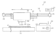
図1に示すように、プリンター11は、印刷媒体の一例として長尺状の印刷用紙である
ロール紙Pに印刷処理(記録処理)を行うシリアルタイプのインクジェット式プリンター
である。こうしたプリンター11は、ロール紙Pに対して印刷処理を行う本体部12と、
本体部12を重力方向における下方から支持する支持用脚部13とを備えている。
Hereinafter, the present invention is an ink jet printer (a type of fluid ejecting apparatus).
Hereinafter, it is simply referred to as “printer”. ) Will be described.
As shown in FIG. 1, the
And a
また、本体部12には、複数(本実施形態では6つ)のインクカートリッジ14が着脱
可能に装着されるホルダー部15と、操作パネル17と、ホルダー部15をその前面から
覆う開閉可能なホルダー用カバー16とが設けられている。各インクカートリッジ14に
は、互いに種類(例えば、色)の異なるインク(流体)がそれぞれ収容されている。また
、操作パネル17は、ユーザーが各種操作を行うためのボタンと、操作状況や操作結果な
どが表示される液晶画面とを有している。
The
本体部12の上側には、ロール紙Pが収容される媒体収容部18が設けられている。こ
の媒体収容部18内に収容されるロール紙Pは、主走査方向Xに沿って延びる軸部材19
に支持されている。媒体収容部18内において主走査方向Xにおける両側には、軸部材1
9を回転自在な状態で支持する軸支持部20がそれぞれ設けられている。そして、軸部材
19が所定の回転方向(図3で矢印で示す方向)に回転することにより、ロール紙Pは本
体部12内に送り出される。なお、媒体収容部18の前面側には、媒体収容部18内に収
容されるロール紙Pを覆う取り外し可能な収容部用カバー21が設けられている。
On the upper side of the
It is supported by. On both sides in the main scanning direction X in the
A
本体部12内には、ロール紙Pに対してインクを噴射するインク噴射部22と、インク
噴射部22に向けてロール紙Pを搬送する搬送装置23(図3参照)と、クリーニング手
段としてのメンテナンス装置24(図2参照)とが設けられている。また、本体部12に
は、ロール紙Pのインク噴射部22を通過した部分(印刷が完了した部分)が排紙される
排紙部25が設けられている。なお、本体部12は、本体部12内を覆うための開閉可能
な本体カバー26を有している。
In the
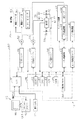
次に、インク噴射部22について説明する。
図2及び図3に示すように、インク噴射部22は、主走査方向X(図2では左右方向)
に延びる支持部材30を備えている。この支持部材30は、主走査方向Xにほぼ直交する
副走査方向(搬送方向)Y(図3参照)において上流側(媒体収容部18側)のほうが下
流側(排紙部25側)よりも上方に位置するように配置されている。すなわち、支持部材
30は、水平面に対して斜状をなす支持面30aを有している。支持部材30の支持面3
0aは、ロール紙Pのうち本体部12内に搬送された部分を支持するようになっている。
Next, the
As shown in FIGS. 2 and 3, the
The
0a is configured to support a portion of the roll paper P that has been conveyed into the
また、インク噴射部22は、主走査方向Xに延びるガイド軸31を備えており、ガイド
軸31は、支持部材30の支持面30aに対向して配置されている。ガイド軸31は、移
動体としてのキャリッジ32を主走査方向Xに沿って往復移動可能な状態で支持している
。
The
図2に示すように、インク噴射部22は、正逆両方向に回転可能なキャリッジモーター
(以下、「CRモーター」ともいう。)33と、CRモーター33から出力された駆動力
をキャリッジ32に伝達するキャリッジ駆動部34とを備えている。このキャリッジ駆動
部34は、本体部12の後面において主走査方向Xにおける両端側に回転自在な状態で支
持される一対のプーリー35,36を有しており、一方(図2では右側)のプーリー35
には、CRモーター33の出力軸(図示略)が動力伝達可能な状態で連結されている。ま
た、一対のプーリー35,36間には、一部がキャリッジ32に連結された無端状のタイ
ミングベルト37が掛装されている。そして、キャリッジ32は、CRモーター33から
の駆動力がキャリッジ駆動部34を介して伝達されることにより、主走査方向Xに沿って
ガイド軸31にガイドされながら移動するようになっている。
As shown in FIG. 2, the
The output shaft (not shown) of the
図6に示すように、キャリッジ32の後面側には、キャリッジ32の主走査方向Xにお
ける位置、移動速度及び移動方向を検出するためのリニアエンコーダー38が設けられて
いる。リニアエンコーダー38は、主走査方向Xに延びる被検出用テープ39と、キャリ
ッジ32に支持される検出部40とを備えている。被検出用テープ39は、本体部12に
移動不能な状態で支持されると共に、主走査方向Xに沿って等間隔に形成される多数のス
リット39aを有している。検出部40は、主走査方向Xにおいて互いに異なる位置に配
置される複数(一例として2つ)のセンサー(図示略)を有している。そして、検出部4
0の各センサーからは、キャリッジ32の移動距離に相当するパルス状の検出信号が制御
回路80にそれぞれ出力されるようになっている。
As shown in FIG. 6, a
From each of the zero sensors, pulse-like detection signals corresponding to the movement distance of the
キャリッジ32上には、各インクカートリッジ14から供給された各種インクを個別に
一時的に貯留する複数(本実施形態では6つ)のサブタンク(図示略)が設けられている
。これら各サブタンクには、インク供給装置41の駆動によって個別対応するインクカー
トリッジ14からインクがそれぞれ供給されるようになっている。
On the
図2及び図3に示すように、キャリッジ32において支持部材30に対向する側には、
流体噴射手段としての印刷ヘッド(印刷手段)42が設けられている。この印刷ヘッド4
2には、サブタンクからインクが供給される複数(図2では6つのみ図示)のノズル43
と、各ノズル43に個別対応する図示しない複数の駆動素子(一例として、圧電素子)と
が設けられている。そして、駆動素子の駆動によってノズル43から支持部材30上に支
持されたロール紙Pに向けてインクが噴射されることで、印刷処理が行われる。
As shown in FIGS. 2 and 3, on the side of the
A print head (printing means) 42 as a fluid ejecting means is provided. This print head 4
2, a plurality of nozzles 43 (only six are shown in FIG. 2) to which ink is supplied from the sub tank.
And a plurality of drive elements (not shown) (piezoelectric elements as an example) corresponding to each
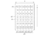
図4に示すように、印刷ヘッド42において支持部材30に対向する対向面は、各ノズ
ル43が開口するノズル形成面44とされている。そして、ノズル形成面44には、副走
査方向Yに沿って等間隔に配置される複数(一例として360個)のノズル43で構成さ
れる複数(本実施形態では6つ)のノズル群45(45A,45B,45C,45D,4
5E,45F,)が形成されている。各ノズル群45は、各インクカートリッジ14(同
種類のインク)に個別対応すると共に、主走査方向Xに沿って所定間隔で配置されている
。
As shown in FIG. 4, the facing surface facing the
5E, 45F,) are formed. The nozzle groups 45 individually correspond to the ink cartridges 14 (the same type of ink) and are arranged at predetermined intervals along the main scanning direction X.
次に、搬送装置23について説明する。
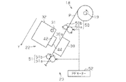
図3に示すように、搬送装置23は、副走査方向Yに沿ってロール紙Pを搬送する装置
である。こうした搬送装置23は、副走査方向Yにおいて支持部材30の上流側(図3で
は右斜め上方であって、媒体収容部18側)に配置される給紙ローラー対50と、副走査
方向Yにおいて支持部材30の下流側(図3では左斜め下方であって、排紙部25側)に
配置される排紙ローラー対51とを備えている。給紙ローラー対50及び排紙ローラー対
51は、紙送りモーター(以下、「PFモーター」ともいう。)52から伝達される駆動
力によって回転する駆動ローラー50a,51aと、駆動ローラー50a,51aの回転
に伴い従動回転する従動ローラー50b,51bとでそれぞれ構成されている。
Next, the
As shown in FIG. 3, the
PFモーター52は、その出力軸近傍に設けられたロータリーエンコーダー53(図6
参照)を用いて回転速度、回転量及び回転方向などが制御されるようになっている。そし
て、PFモーター52が正転駆動されて各駆動ローラー50a,51aが図3で示す矢印
方向に回転することにより、各ローラー対50,51に挟持されるロール紙Pは、副走査
方向Yにおいて排紙部25側に紙送り(搬送)されるようになっている。なお、本実施形
態では、PFモーター52が逆転駆動される場合、各駆動ローラー50a,51aには、
PFモーター52から駆動力が伝達されない。
The
The rotation speed, the rotation amount, the rotation direction, and the like are controlled by using (see). Then, the roll paper P sandwiched between the roller pairs 50 and 51 is moved in the sub-scanning direction Y by the
The driving force is not transmitted from the
次に、メンテナンス装置24について説明する。
図2に示すように、支持部材30の主走査方向Xにおける一方側(図2では右側)は、
ロール紙Pが供給されないホームポジションとされている。そして、メンテナンス装置2
4はこのホームポジションに設けられている。メンテナンス装置24は、キャップ60と
、キャップ60を昇降移動させる昇降機構61と、吸引ポンプ62とを備えている。吸引
ポンプ62は、PFモーター52が逆転駆動されることで駆動されるようになっている。
なお、吸引ポンプ62と搬送装置23との動力源は別々に設けてもよい。
Next, the
As shown in FIG. 2, one side (right side in FIG. 2) of the
The home position is such that the roll paper P is not supplied. And maintenance device 2
4 is provided at this home position. The
In addition, you may provide the motive power source of the
図5に示すように、キャップ60は、印刷ヘッド42に対向する側に開口するように配
置されている。また、キャップ60内には、ホームポジションに位置する印刷ヘッド42
から噴射(排出)されたインクを吸収するインク吸収材63が収容されている。そして、
印刷ヘッド42をホームポジションに配置した状態で、ノズル43からキャップ60内の
インク吸収材63に対してインクを噴射させることで、メンテナンス処理の1つであるフ
ラッシングが行われる。また、キャップ60を昇降機構61によって上昇移動させて、ノ
ズル43を囲むようにノズル形成面44に当接させることで、ノズル43の乾燥を抑制す
るためのキャッピングが行われる。
As shown in FIG. 5, the
An
Flushing, which is one of maintenance processes, is performed by ejecting ink from the
さらに、キャッピングした状態で吸引ポンプ62を駆動させることで、メンテナンス処
理の1つである吸引クリーニングが行われる。吸引クリーニングでは、吸引ポンプ62を
駆動させることでキャップ60内に負圧を発生させ、この負圧を吸引力としてノズル43
内に作用させることで、ノズル43内の増粘したインクや気泡をキャップ60内に排出さ
せるようになっている。なお、キャップ60内に排出されたインクは、図示しない廃液回
収チューブを通じて廃液タンク(図示略)に排出されるようになっている。
Further, by driving the
By acting inside, the thickened ink and bubbles in the
吸引クリーニングにおいては、吸引ポンプ62の駆動速度及び駆動時間を変化させるこ
とで、キャップ60内に発生させる負圧(ノズル43に付与する負圧)の大きさを変化さ
せるようになっている。ここで、吸引ポンプ62の駆動速度が高速になるほど吸引力は強
くなり、駆動時間が長くなるほど吸引量が多くなる。そして、吸引力が小さく吸引時間も
短い弱クリーニングと、吸引力が大きく吸引時間も長い強クリーニングとは、状況に応じ
て選択して実行されるようになっている。
In the suction cleaning, the magnitude of the negative pressure (negative pressure applied to the nozzle 43) generated in the
メンテナンス装置24には、印刷ヘッド42におけるインク噴射不良(流体噴射不良)
のノズル43(以下、これを「不良ノズル」ともいう。)の有無を検査するノズル検査手
段としてのノズル検査装置64が設けられている。なお、不良ノズルとは、ノズル43内
の目詰まりや気泡の混入などによってインクを噴射できない、又はノズル43内のインク
の粘度が高くなることで適切な量のインクを噴射できないノズル43のことを示している
。
The
A
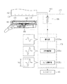
ノズル検査装置64は、キャップ60内においてインク吸収材63の上面(印刷ヘッド
42に対向する側の面)を覆う金属製の網材(電極部)65と、キャップ60の底部中央
に配置された+側の端子66とを備えており、網材65は、+側の端子66に電気的に接
続されている。また、ノズル検査装置64には、ノズル検査回路67(図5では破線で囲
まれた部分)が電気的に接続されている。
The
ノズル検査回路67には、網材65と印刷ヘッド42のノズル形成面44との間に電圧
を印加するための電圧印加回路68と、網材65とノズル形成面44との間の電圧値の変
化を検出する電圧検出装置69とが設けられている。電圧印加回路68は、網材65が正
極になると共にノズル形成面44が負極になるように、直流電源(例えば400V)と抵
抗素子(例えば1MΩ)とを備えている。そのため、網材65において印刷ヘッド42に
対向する面(図5では上面)には、正の電荷が帯電する一方で、印刷ヘッド42のノズル
形成面44には、負の電荷が帯電するようになっている。
The
電圧検出装置69は、網材65からの検出信号を積分して出力する積分回路69aと、
積分回路69aから出力された信号を反転増幅して出力する反転増幅回路69bと、反転
増幅回路69bから出力された信号をA/D変換してコントローラー86へ出力するA/
D変換回路69cとを備えている。
The
An inverting
D conversion circuit 69c.
そして、ノズル検査装置64によるノズル検査時には、検査対象となるノズル43から
インクがキャップ60内に噴射される。このとき、ノズル43から噴射されたインクには
、負の電荷が帯電している。こうしたインクが網材65に接近するに連れて、網材65で
は、静電誘導によって正の電荷が次第に増加する。その結果、網材65と印刷ヘッド42
のノズル形成面44との間の電位差は、静電誘導に基づく誘導電圧により、ノズル43か
らインクが噴射されない場合と比較して大きくなる。
At the time of nozzle inspection by the
The potential difference between the
そして、インクが網材65に着弾すると、網材65の正の電荷の一部が、インクに帯電
していた負の電荷によって中和される。すると、網材65と印刷ヘッド42のノズル形成
面44との間の電位差(電圧)は、ノズル43からインクが噴射されない場合と比較して
小さくなる。その後、網材65と印刷ヘッド42のノズル形成面44との間の電位差は、
当初の大きさに戻る。こうした電位差に関する検出信号は、積分回路69a、反転増幅回
路69b及びA/D変換回路69cを介してコントローラー86に入力される。
When the ink lands on the
Return to the original size. A detection signal relating to such a potential difference is input to the
すると、コントローラー86では、A/D変換回路69cから入力された検出信号の振
幅Vd(網材65と印刷ヘッド42のノズル形成面44との間の電圧値の変化量)が検出
される。そして、検出された振幅Vdが予め設定された振幅閾値以上である場合には、検
査対象のノズル43が正常ノズルであると判定される一方、検出された振幅Vdが振幅閾
値未満である場合には、検査対象のノズル43が不良ノズルであると判定される。
Then, the
次に、プリンター11の電気的構成について説明する。
図6に示すように、プリンター11には、ホスト装置HCが図示しない通信ケーブルを
介して接続されている。すなわち、プリンター11の制御回路80は、インターフェイス
IFを介してホスト装置HCとの間で印刷データなどの各種情報を送受信可能とされてい
る。また、制御回路80のインターフェイスIFには、ユーザーによる操作パネル17の
操作結果に関する操作情報が入力される。
Next, the electrical configuration of the
As shown in FIG. 6, the host device HC is connected to the
ホスト装置HCは、制御装置CNTと、画像データを表示可能な表示手段としてのモニ
ターMNとを備えている。制御装置CNTには、印刷データを生成するプリンタードライ
バーPDが、ホスト装置HCのCPU(図示略)とプログラムとにより構築されている。
プリンタードライバーPDは、印刷データを複数に分割し、該分割された複数のデータを
プリンター11側に順次送信させる。なお、プリンタードライバーPDは、始めにホスト
装置HC側で設定された印刷条件に関するデータをプリンター11側に送信させる。印刷
条件は、印刷モード(ドラフト印刷モード又は高詳細印刷モード)、用紙の種類、用紙の
サイズなどを含んでいる。
The host device HC includes a control device CNT and a monitor MN as display means capable of displaying image data. In the control device CNT, a printer driver PD that generates print data is constructed by a CPU (not shown) of the host device HC and a program.
The printer driver PD divides the print data into a plurality of pieces and sequentially transmits the divided pieces of data to the
次に、プリンター11の制御回路80について説明する。
制御回路80は、CPU81、ASIC82(Application Specif
ic IC(特定用途向けIC))、ROM83、不揮発性メモリー84及びRAM85
を有するコントローラー86(図4では一点鎖線で囲まれた部分)を備えている。このコ
ントローラー86は、バス87を介して、ノズル検査回路67及び各種ドライバー88,
89,90,91に電気的に接続されている。
Next, the
The
ic IC (specific application IC)),
And a controller 86 (a portion surrounded by a one-dot chain line in FIG. 4). The
89, 90, 91 are electrically connected.
コントローラー86は、PF用ドライバー88を介してPFモーター52を制御すると
共に、CR用ドライバー89を介してCRモーター33を制御する。また、コントローラ
ー86は、ヘッド用ドライバー90を介して印刷ヘッド42(具体的には、印刷ヘッド4
2内の各駆動素子)を制御すると共に、インク供給用ドライバー91を介してインク供給
装置41を制御する。
The
2) and the
ROM83には、各種制御プログラム及び各種データなどが記憶されている。不揮発性
メモリー84には、ファームウェアプログラムを始めとする各種プログラム及び印刷処理
に必要な各種データなどが記憶されている。RAM85には、CPU81によって実行さ
れるプログラムデータ、CPU81による演算結果及び処理結果である各種データ、並び
にASIC82で処理された各種データなどが一時記憶される。また、RAM85は、ホ
スト装置HCから受信した印刷データが格納されるデータ領域を有している。
The
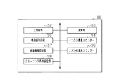
次に、本実施形態のコントローラー86について説明する。
図7に示すように、コントローラー86は、ハードウェア及びソフトウェアのうち少な
くとも一方により実現される機能部分として、主制御部92、演算部93、インク消費量
カウンター94、噴射量取得手段としての噴射量取得部95、ノズル検査用カウンター9
6、検査頻度設定手段としての検査頻度設定部97及びクリーニング条件設定手段として
のクリーニング条件設定部98を有する。なお、インク消費量カウンター94及びノズル
検査用カウンター96は、同種類のインクを噴射するノズル群45毎に設けられる。
Next, the
As shown in FIG. 7, the
6. It has an inspection
演算部93は、印刷データに基づいて、印刷ジョブで噴射されたインクの量を色毎に積
算する。すなわち、演算部93は、色別のドットカウンター(図示省略)を内蔵し、各ド
ットカウンターの計数値に基づいて色別にインク消費量を演算する。各ドットカウンター
はRAM85の色別の領域に格納された対応する色の印字データ(イメージデータ)を入
力可能に構成され、入力したデータ値(0/1)に応じてドットの数を計数する計数処理
を行う。本実施形態の印字データは、印刷ヘッド42が大・中・小の3種類のドットを形
成できるように、大ドットが「11」、中ドットが「10」、小ドットが「01」、無ド
ットが「00」の値をとる。各ドットカウンターは、小ドット、中ドット、大ドットを個
別に計数する。
The
そして、演算部93は、ドットカウンターの計数値を読み出し、ドットサイズ別の各計
数値に、ドットサイズ別の係数をそれぞれ乗じることでドットサイズ毎のインク消費量を
演算し、これらをインク色別に全て加算して各インク色のインク消費量を演算する。そし
て、演算部93は、各インク色のインク消費量をインク消費量カウンター94に加算する
。なお、印刷中においてはノズル43内のメニスカスを整えるために定期的にフラッシン
グが行われる。このフラッシングは、印刷データに基づいたインクの噴射ではないが、演
算部93は、印刷中にフラッシングが行われた場合には、そのフラッシング時におけるイ
ンクの噴射量も積算し、各インク色のインク消費量を算出する。
The
インク消費量カウンター94は、プリンター11でのインク消費量の総量をインク色毎
に管理している。こうしたインク消費量カウンター94は、RAM85の一部によって構
成される第1格納部(図示略)と、不揮発性メモリー84の一部によって構成される第2
格納部(図示略)とを有している。プリンター11の電源オン時において、第1格納部に
は、演算部93によって演算されたインク消費量に基づき、プリンター11でのインク消
費量の総量がインク色毎に格納される。一方、プリンター11の電源がオフになった場合
、第1格納部に格納される値、すなわちインク消費量の総量は、第2格納部に退避される
。その後、プリンター11の電源がオンになった場合、第2格納部に退避された値、すな
わちインク消費量の総量は、第1格納部にコピーされる。
The
And a storage unit (not shown). When the
噴射量取得部95は、印刷ジョブに基づく印刷処理の直前に各インク消費量カウンター
94の値を読み出すと共に、印刷処理後に各インク消費量カウンター94の値を読み出す
。そして、噴射量取得部95は、印刷処理前のインク消費量カウンター94の値と、印刷
処理後のインク消費量カウンター94の値との差を算出することで、その印刷ジョブにお
けるインクの噴射量V(図8,9参照)をノズル群45毎(インク色毎)に取得する。
The ejection
ノズル検査用カウンター96には、ノズル検査間に実行される印刷ジョブのうち、イン
クの消費を伴うものの数、すなわちカウント値N(図9参照)が格納される。
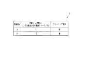
図8は、ノズル検査で不良ノズルが検出された場合のクリーニング条件を決めるために
参照するクリーニング条件判定テーブル(以下、「判定テーブルT」ともいう。)の一例
である。図8に示すように、判定テーブルTは、1回の印刷ジョブでのインクの噴射量V
と、ノズル検査間に実行される印刷ジョブ数Njと、クリーニング強度との関係を示すテ
ーブルデータである。なお、図8の判定テーブルTにおいては、所定の閾値以上の噴射量
Vを「大」、所定の閾値未満の噴射量Vを「小」としているが、判定テーブルTに具体的
な噴射量の閾値をいれておいてもよい。また、この閾値は、インクの種類に応じて異なっ
てもよい。
The nozzle inspection counter 96 stores the number of print jobs that are performed between nozzle inspections that involve ink consumption, that is, the count value N (see FIG. 9).
FIG. 8 is an example of a cleaning condition determination table (hereinafter also referred to as “determination table T”) that is referred to in order to determine a cleaning condition when a defective nozzle is detected in the nozzle inspection. As shown in FIG. 8, the determination table T includes an ink ejection amount V in one print job.
Table data showing the relationship between the number of print jobs Nj executed between nozzle inspections and the cleaning intensity. In the determination table T of FIG. 8, the injection amount V equal to or greater than the predetermined threshold is “large” and the injection amount V less than the predetermined threshold is “small”. A threshold value may be entered. Further, this threshold value may vary depending on the type of ink.
検査頻度設定部97は、噴射量取得部95で取得されたインクの噴射量Vが予め規定さ
れた閾値以上(すなわち、「大」)であるか否かを判定して、対応するノズル群45毎に
ノズル検査の実行頻度Frを設定する。具体的には、検査頻度設定部97は、インクの噴
射量Vが「大」であれば、判定テーブルTを参照し、ノズル検査間に実行される印刷ジョ
ブ数Njを「1」に設定する。同様に、検査頻度設定部97は、インクの噴射量Vが予め
規定された閾値未満(すなわち、「小」)であれば、判定テーブルTを参照し、ノズル検
査間に実行される印刷ジョブ数Njを「10」に設定する。なお、設定された印刷ジョブ
数Njは、RAM85に書き込まれる。
The inspection
そして、Nj=1の場合には、ノズル検査用カウンター96のカウント値Nが1つ加算
される毎にノズル検査が実行されるので、この場合のノズル検査の実行頻度Fr(=1/
Nj)は1/1となる。また、Nj=10の場合には、ノズル検査用カウンター96のカ
ウント値Nが10まで加算されるとノズル検査が実行されるので、この場合のノズル検査
の実行頻度Frは1/10となる。すなわち、検査頻度設定部97は、インクの噴射量V
が多いほど、ノズル検査の実行頻度Frを高く(ノズル検査間に実行される印刷ジョブ数
Njを少なく)設定する。
In the case of Nj = 1, the nozzle inspection is executed every time the count value N of the
Nj) is 1/1. Further, when Nj = 10, the nozzle inspection is executed when the count value N of the
As the number increases, the nozzle inspection execution frequency Fr is set higher (the number of print jobs Nj executed between nozzle inspections is smaller).
ここで、ノズル検査の実行頻度Frが高いと、不良ノズルは発生して間もなく検出され
ることになる一方、ノズル検査の実行頻度Frが低いと、不良ノズルは発生後時間がたっ
てから検出される可能性が高くなる。また、ノズル43のインク噴射不良の度合いは、発
生してからの経過時間が長くなると重度になる可能性がある。そして、検出された不良ノ
ズルはインク噴射不良の度合いが低ければ、吸引力の小さい吸引クリーニングで解消でき
る可能性が高いが、インク噴射不良の度合いが高ければ、吸引力の大きい吸引クリーニン
グでなければ解消できない可能性が高い。
Here, when the nozzle inspection execution frequency Fr is high, defective nozzles are generated and detected soon. On the other hand, when the nozzle inspection execution frequency Fr is low, defective nozzles are detected after a certain time has elapsed. The possibility increases. In addition, the degree of ink ejection failure of the
そのため、本実施形態においては、クリーニング条件設定部98が、ノズル検査の実行
頻度Frに応じて、クリーニング条件を設定する。具体的には、クリーニング条件設定部
98は、Nj=1であれば、判定テーブルTを参照し、クリーニング強度を「弱」に設定
する。同様に、クリーニング条件設定部98は、Nj=10であれば、判定テーブルTを
参照し、クリーニング強度を「強」に設定する。つまり、クリーニング条件設定部98は
、ノズル検査の実行頻度Frが低いほど、ノズル43に作用する吸引力が大きくなるよう
に、クリーニング条件(クリーニング強度)を設定する。なお、設定されたクリーニング
強度は、RAM85に書き込まれる。
Therefore, in the present embodiment, the cleaning
次に、プリンター11におけるノズル検査及びクリーニング処理について説明する。
印刷ヘッド42において不良ノズルが発生すると、ドット抜けが生じ、印刷品質が低下
してしまう。そこで、コントローラー86は、メンテナンス処理としてノズル検査装置6
4にノズル検査を実行させる。
Next, nozzle inspection and cleaning processing in the
When defective nozzles occur in the
4 causes the nozzle inspection to be executed.
ただし、ノズル検査は印刷処理を中断して行わなければならないし、インクも消費され
るので、インクの噴射量Vに応じて決定されたタイミングで実行される。すなわち、イン
クの噴射量Vが多くなれば、使用されるノズル43に気泡や異物が混入する確率が高くな
るし、使用されないノズル43におけるインクの滞留時間が長くなるので、不良ノズルが
発生する確率が高まる。そのため、不良ノズルが発生する確率が高くなった段階でノズル
検査を行う。
However, the nozzle inspection must be performed while the printing process is interrupted, and since ink is consumed, it is executed at a timing determined according to the ink ejection amount V. That is, if the ink ejection amount V is increased, the probability that bubbles or foreign matters are mixed into the
なお、例えば1の印刷ジョブの途中で印刷処理を中断してノズル検査を行うと、中断し
た前後に形成された画像で色差が発生し、印刷品質が低下してしまう。そこで、本実施形
態においては、印刷ジョブが終了する毎に、噴射量取得部95がその印刷ジョブで噴射さ
れたインクの噴射量Vを取得して、検査頻度設定部97が印刷ジョブ数Njを設定すると
共に、クリーニング条件設定部98がクリーニング強度を設定する。
For example, if the printing process is interrupted in the middle of one print job and the nozzle inspection is performed, a color difference occurs between the images formed before and after the interruption, and the print quality deteriorates. Therefore, in this embodiment, every time a print job is completed, the ejection
また、主制御部92は、検査頻度設定部97によって設定された印刷ジョブ数Njに基
づいたタイミングで、ノズル検査装置64にノズル検査を実行させる。具体的には、主制
御部92は、ノズル検査用カウンター96のカウント値Nが印刷ジョブ数Nj以上になる
と、N≧Njになったノズル群45について、検査要求フラグをオンにする。すなわち、
検査要求フラグは、ノズル群45毎に設定される。なお、主制御部92は、ユーザーから
操作パネル17やホスト装置HCを通じてノズル検査の実行が指示された場合にも、検査
要求フラグをオンにする。
Further, the
The inspection request flag is set for each nozzle group 45. Note that the
そして、主制御部92は、印刷ジョブを受信すると、その印刷処理を実行する前にノズ
ル検査が実行されるタイミングであるか否かを判断し、検査要求フラグがオンになってい
るノズル群45についてノズル検査を実行する。このノズル検査によって不良ノズルが検
出された場合には、その不良ノズルからインクを吸引させるために、主制御部92がメン
テナンス装置24を駆動して吸引クリーニングを実行させる。そして、主制御部92は、
吸引クリーニングの実行時に、RAM85から読み出したクリーニング強度に応じた回転
速度及び駆動時間で吸引ポンプ62が駆動されるように、その動力源であるPFモーター
52を制御する。したがって、本実施形態では、主制御部92が、ノズル検査装置64を
含むメンテナンス装置24を制御する制御手段として機能する。
When the
When the suction cleaning is executed, the
なお、プリンター11の電源が遮断された場合などには、RAM85に記憶された印刷
ジョブ数Njやクリーニング強度がリセットされる。この場合には、次の印刷処理が行わ
れるまでの待機時間が長くなる可能性が高いので、電源投入後の最初の印刷処理前などに
別途ノズル検査やクリーニングを行う。
When the
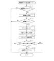
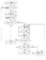
次に、印刷ジョブに基づく印刷処理が終了したときにコントローラー86が実行する検
査要求フラグ設定処理ルーチンについて、図9に示すフローチャートに基づき説明する。
まず、ステップS11では、主制御部92が、すべてのノズル群45に対応する検査要
求フラグがオンになっているか否かを判断する。そして、すべてのノズル群45に対応す
る検査要求フラグがオンになっている場合には処理を終了する一方、いずれかの検査要求
フラグがオフになっている場合には、ステップS12に進む。
Next, an inspection request flag setting process routine executed by the
First, in step S11, the
ステップS12では、噴射量取得部95が今回の印刷ジョブにおけるインクの噴射量V
をノズル群45毎に取得して、ステップS13に進む。
ステップS13では、主制御部92がその噴射量Vがゼロより大きいか否かをノズル群
45毎に判断する。そして、すべてのノズル群45の噴射量Vがゼロ以下である場合には
処理を終了する一方、いずれかのノズル群45の噴射量Vがゼロより大きい場合には、ス
テップS14に進む。
In step S12, the ejection
Is acquired for each nozzle group 45, and the process proceeds to step S13.
In step S13, the
ステップS14では、主制御部92が、噴射量Vがゼロでなかったノズル群45につい
て、ノズル検査用カウンター96のカウント値Nを1つ加算して、ステップS15に進む
。
In step S14, the
ステップS15では、検査頻度設定部97が、判定テーブルTを参照し、カウント値N
が加算されたノズル群45について、噴射量取得部95によって取得された噴射量Vに対
応する印刷ジョブ数Njを設定して、ステップS16に進む。これにより、インクの噴射
量が多いほど、ノズル検査の実行頻度Frが高く設定される。
In step S15, the inspection
For the nozzle group 45 to which is added, the number of print jobs Nj corresponding to the ejection amount V acquired by the ejection
ステップS16では、クリーニング条件設定部98が、判定テーブルTを参照し、検査
頻度設定部97によって設定された印刷ジョブ数Njに対応するクリーニング強度を設定
して(クリーニング条件設定ステップ)、ステップS17に進む。これにより、ノズル検
査の実行頻度Frに応じて、すなわちノズル検査の実行頻度Frが低い程、クリーニング
強度が高くなるようにクリーニング条件が設定される。
In step S16, the cleaning
ステップS17では、主制御部92が、ノズル検査用カウンター96のカウント値Nが
印刷ジョブ数Nj以上であるか否かを判断する。そして、主制御部92は、すべてのノズ
ル群45についてN<Njの場合には処理を終了する一方、いずれかのノズル群45につ
いてN≧Njの場合にはステップS18に進む。
In step S <b> 17, the
ステップS18では、主制御部92がN≧Njとなったノズル群45の検査要求フラグ
をオンにして、処理を終了する。
次に、ホスト装置HCからの印刷データの受信を契機に印刷を行う際にコントローラー
86が実行するメンテナンス処理ルーチンについて説明する。
In step S18, the
Next, a maintenance processing routine executed by the
図10に示すように、まずステップS21では、主制御部92がノズル検査の実行タイ
ミングであるか否かを判断する。詳しくは、主制御部92はすべての検査要求フラグがオ
フであればノズル検査の実行タイミングではないと判断して処理を終了する一方、いずれ
かのノズル群45の検査要求フラグがオンであればノズル検査の実行タイミングであると
判断してステップS22に進む。
As shown in FIG. 10, first, in step S21, the
ステップS22では、主制御部92が、検査要求フラグがオンになっているノズル群4
5に対してノズル検査を実行して、ステップS23に進む。すなわち、主制御部92はノ
ズル検査装置64を動作させると共に、検査対象とされるノズル群45の各ノズル43か
ら検査順に従って順次インク滴を噴射させる。
In step S22, the
Nozzle inspection is executed for 5, and the process proceeds to step S23. That is, the
ステップS23では、主制御部92が、ノズル検査を行ったノズル群45に対する検査
要求フラグをオフにすると共に、ノズル検査を行ったノズル群45に対するノズル検査用
カウンター96のカウント値Nをリセットして、ステップS24に進む。
In step S23, the
ステップS24では、主制御部92が、ノズル検査時に電圧検出装置69から出力され
た検出信号に基づいて、検査対象である各ノズル43の中に不良ノズルがあるか否かを判
断する。そして、主制御部92は、不良ノズルがなかった場合には処理を終了する一方、
不良ノズルがあった場合にはステップS25に進む。
In step S24, the
If there is a defective nozzle, the process proceeds to step S25.
ステップS25では、主制御部92が、不良ノズルを含むノズル群45について設定さ
れたクリーニング強度をRAM85から読み出して、ステップS26に進む。
ステップS26では、主制御部92が、読み出したクリーニング強度でメンテナンス装
置24に吸引クリーニングを実行させて(クリーニングステップ)、ステップS27に進
む。なお、本実施形態のメンテナンス装置24は、キャップ60が1つしかないので、す
べてのノズル群45に対して吸引クリーニングが行われる。
In step S25, the
In step S26, the
このとき、ノズル群45A〜45Fのうち、異なる複数のノズル群45の中に、それぞ
れ不良ノズルが存在することがあり得る。そして、不良ノズルが存在する各ノズル群45
に設定されているクリーニング強度が互いに異なる可能性もある。この場合には、不良ノ
ズルが存在するノズル群45に設定されたクリーニング条件のうち、強い方の強度で吸引
クリーニングが実行される。また、吸引クリーニングの実行後、主制御部92はすべての
ノズル検査用カウンター96のカウント値Nをリセットする。
At this time, defective nozzles may exist in the plurality of different nozzle groups 45 among the nozzle groups 45A to 45F. And each nozzle group 45 in which a defective nozzle exists
There is also a possibility that the cleaning strengths set in the above are different from each other. In this case, suction cleaning is executed with the stronger one of the cleaning conditions set for the nozzle group 45 in which the defective nozzle exists. Further, after the suction cleaning is executed, the
ステップS27では、不良ノズルが検出されたノズル群45について主制御部92がノ
ズル検査を実行して、ステップS28に進む。すなわち、主制御部92は、吸引クリーニ
ングによってノズル43のインク噴射不良が解消されたか否かを確認する。なお、ここで
は、ステップS22でのノズル検査で不良ノズルと判断されたノズル43に対してのみ、
ノズル検査を実行してもよい。
In step S27, the
A nozzle inspection may be performed.
ステップS28では、主制御部92が、不良ノズルの有無を判断して、不良ノズルがな
かった場合には処理を終了する一方、不良ノズルがあった場合にはステップS29に進む
。
In step S28, the
ステップS29では、主制御部92が、設定されたクリーニング強度が「強」であるか
否かを判断する。そして、クリーニング強度が「強」であった場合には、ステップS30
に進む一方、クリーニング強度が「強」でなかった場合、すなわち「弱」であった場合に
は、ステップS31に進む。
In step S29, the
On the other hand, if the cleaning intensity is not “strong”, that is, if it is “weak”, the process proceeds to step S31.
ステップS30では、主制御部92が操作パネル17やホスト装置HCのモニターMN
を通じてエラー表示を行う。すなわち、強クリーニングでノズル43の不良が解消されな
かった場合には、その旨をユーザーに報知する。なお、エラーを報知する手段は、モニタ
ーMN等への表示に限らず、エラー音やランプの点滅などによって行ってもよい。
In step S30, the
Error display through. That is, when the defect of the
ステップS31では、クリーニング条件設定部98がクリーニング強度を「強」に設定
して、ステップS25に進む。すなわち、弱クリーニングでノズル43のインク噴射不良
が解消できなかったので、ノズル43にさらに大きい吸引力を作用させるために、クリー
ニング強度を変更する。そして、主制御部92は、ステップS25に続くステップS26
で強クリーニングを実行し、ステップS28で不良ノズルが検出されなければ、処理を終
了する。一方、このステップS28で不良ノズルが検出されると、ステップS29で肯定
判定となるので、ステップS30に進み、主制御部92がエラー表示を行う。
In step S31, the cleaning
In step S28, if the defective nozzle is not detected, the process ends. On the other hand, if a defective nozzle is detected in step S28, an affirmative determination is made in step S29, so that the process proceeds to step S30 and the
これにより、印刷を開始する前に、不良ノズルが存在しないことが確認したり、不良ノ
ズルが存在しない状態にしたりすることができるので、印刷品質の低下を抑制することが
できる。また、強クリーニングでもノズル43のインク噴射不良が解消されない場合には
エラー表示が行われるので、無駄なクリーニング処理の実行を抑制することができる。
Thereby, before starting printing, it can be confirmed that there is no defective nozzle, or a state in which there is no defective nozzle can be obtained, so that it is possible to suppress a decrease in print quality. In addition, if the ink ejection failure of the
以上説明した実施形態によれば、以下のような効果を得ることができる。
(1)ノズル検査の実行頻度Frに関係なくクリーニング条件が設定される場合と比較
して、適切にクリーニング条件を設定することができる。例えば、ノズル43のインク噴
射不良は、発生してからの経過時間が長くなると不良の度合いが増し、圧力(吸引力)の
強いクリーニングでなければ不良を解消できないことがある。そのため、実行頻度Frに
関係なく圧力の弱いクリーニングを行うと、その後に圧力の強いクリーニングを追加的に
行うことになり、最初のクリーニングの分、時間やインクを無駄に消費してしまうおそれ
がある。一方、ノズル検査の実行頻度Frが高ければ、不良の度合いが低いうちに不良ノ
ズルを検出することができるのに、実行頻度Frに関係なく圧力の強いクリーニングを行
うと、インクが無駄に消費されるおそれがある。したがって、ノズル検査の実行頻度Fr
に応じてクリーニングの条件を設定することで、無駄に消費される時間やインクの量を低
減し、効率よくクリーニングを実行することができる。
According to the embodiment described above, the following effects can be obtained.
(1) The cleaning condition can be appropriately set as compared with the case where the cleaning condition is set regardless of the nozzle inspection execution frequency Fr. For example, the ink ejection failure of the
By setting the cleaning conditions according to the above, it is possible to reduce wasteful time and the amount of ink and to perform cleaning efficiently.
(2)ノズル検査の実行頻度Frが低いときには吸引力が大きくなるようにクリーニン
グの条件が設定されるので、検出された時点でのインク噴射不良の度合いが高い場合にも
、吸引力の大きい1回のクリーニングでインク噴射不良を解消することが可能になる。ま
た、ノズル検査の実行頻度Frが高いときには吸引力が小さくなるようにクリーニングの
条件が設定されるが、このときには検出された時点でのインク噴射不良の度合いが低い可
能性が高いので、吸引力の小さいクリーニングでもインク噴射不良を解消することができ
る。したがって、吸引力の小さいクリーニングを無駄に実行したり、過度に大きい吸引力
のクリーニングを実行したりすることなく、少ないクリーニングの実行回数でインク噴射
不良を解消すると共に、吸引クリーニングに伴う流体の消費量を少なくすることができる
。
(2) Since the cleaning condition is set so that the suction force is increased when the nozzle inspection execution frequency Fr is low, even when the degree of ink ejection failure at the time of detection is high, the
(3)インクの噴射量Vが多いほどノズル検査の実行頻度Frが高く設定されるので、
インクの噴射量Vが増してノズル43内への気泡の混入などによってインク噴射不良が発
生する確率が高くなるタイミングで、ノズル検査を実行することができる。そのため、1
回の印刷ジョブでのインクの噴射量Vが少ないにもかかわらず、1回の印刷ジョブ毎にノ
ズル検査が実行されることを抑制でき、プリンター11の印刷速度を向上させることがで
きる。一方、1回の印刷ジョブでのインクの噴射量Vが多い場合には、1回の印刷ジョブ
毎にノズル検査が実行されるため、不良ノズルの速やかな検出に貢献できる。すなわち、
適切なタイミングでノズル検査を実行することができる。
(3) As the ink ejection amount V increases, the nozzle inspection execution frequency Fr is set higher.
Nozzle inspection can be performed at a timing when the ink ejection amount V increases and the probability of ink ejection failure occurring due to air bubbles entering the
Even though the ink ejection amount V in a single print job is small, the nozzle inspection can be suppressed from being executed for each print job, and the printing speed of the
Nozzle inspection can be performed at an appropriate timing.
(4)1回の印刷ジョブでのインクの噴射量Vがノズル群45毎に取得されると共に、
ノズル検査の実行頻度Frがノズル群45毎に設定されるので、ノズル群45毎に噴射量
Vが異なる場合にも、ノズル群45毎に適切なタイミングでノズル検査を行うことができ
る。
(4) The ink ejection amount V in one print job is acquired for each nozzle group 45, and
Since the nozzle inspection execution frequency Fr is set for each nozzle group 45, the nozzle inspection can be performed at an appropriate timing for each nozzle group 45 even when the injection amount V is different for each nozzle group 45.
なお、上記実施形態は以下のように変更してもよい。
・設定した印刷ジョブ数Njやクリーニング強度を不揮発性メモリー84に書き込むよ
うにして、プリンター11の電源を遮断した場合にも設定情報を残しておくようにしても
よい。
In addition, you may change the said embodiment as follows.
The setting information may be left even when the
・Njは、印刷ジョブ数に限らず、例えばページ数など、所定の印刷単位に変更するこ
とができる。また、Njの値も任意の値に変更することができる。
・ノズル検査の実行頻度Frは、インクの噴射量に限らず、前回のノズル検査からの経
過時間や印刷条件(印刷モード、用紙の種類、用紙のサイズなど)に基づいて設定しても
よい。さらに、フラッシングやワイピングなどのメンテナンス処理の実行状況に応じて、
ノズル検査の実行頻度Frを変化させてもよい。
Nj is not limited to the number of print jobs, and can be changed to a predetermined print unit such as the number of pages. Also, the value of Nj can be changed to an arbitrary value.
The nozzle inspection execution frequency Fr is not limited to the ink ejection amount, and may be set based on the elapsed time from the previous nozzle inspection and the printing conditions (printing mode, paper type, paper size, etc.). Furthermore, depending on the execution status of maintenance processing such as flushing and wiping,
The execution frequency Fr of nozzle inspection may be changed.
・例えばインク溶媒に顔料を分散させた顔料インクなどでは、顔料濃度によってインク
の増粘のしやすさが異なるので、増粘しにくいインクを噴射するノズル群45では、増粘
しやすいインクを噴射するノズル群45よりも、ノズル検査の実行頻度Frを低くしても
よい。あるいは、増粘しにくいインクを噴射するノズル群45では、ノズル検査の実行頻
度Frにかかわらず弱クリーニングを行うようにしてもよい。
-For example, in the case of pigment ink in which a pigment is dispersed in an ink solvent, the ease of thickening the ink differs depending on the pigment concentration. The nozzle inspection execution frequency Fr may be lower than that of the nozzle group 45 to be used. Alternatively, in the nozzle group 45 that ejects ink that is hard to thicken, weak cleaning may be performed regardless of the nozzle inspection execution frequency Fr.
・クリーニング条件は、例えばキャップ60内の負圧を高めてからその負圧をノズル4
3に作用させるチョーククリーニング(強クリーニング)など、吸引クリーニングの種類
でその強弱を変化させるようにしてもよい。あるいは、弱クリーニングとしてノズル43
からインクを排出させないクリーニングを行い、強クリーニングとしてノズル43からイ
ンクを排出させるクリーニングを行うようにしてもよい。なお、ノズル43からインクを
排出させないクリーニングとしては、例えば駆動素子の連続的な駆動によって振動を与え
、ノズル43内の気泡をノズル43外に移動させるものがある。
The cleaning condition is, for example, increasing the negative pressure in the
The strength may be changed depending on the type of suction cleaning, such as choke cleaning (strong cleaning). Alternatively, the
Cleaning that does not discharge ink from the
・クリーニング方法として、加圧によりノズル43からインクを排出させる加圧クリー
ニングを採用してもよい。
・クリーニング強度は、3段階以上の複数段階に設定してもよい。
As a cleaning method, pressure cleaning in which ink is discharged from the
-The cleaning strength may be set in a plurality of stages of three or more.
・同種類の流体に対応する複数のノズル列が設けられている場合には、複数列のノズル
列を1つのノズル群としてもよい。また、ノズル列を構成するノズル43に限らず、例え
ば使用頻度や配置に応じたノズル群など、任意のノズル43から構成されるノズル群毎に
ノズル検査等を行うようにしてもよい。
When a plurality of nozzle rows corresponding to the same type of fluid are provided, the plurality of nozzle rows may be used as one nozzle group. Further, not only the
・複数の印刷ヘッド42を備える場合には、ノズル検査の実行頻度Fr、すなわち印刷
ジョブ数Njを、インクの種類毎(すなわち、ノズル群45毎)に設定するのではなく、
印刷ヘッド42単位で設定してもよい。この場合、印刷ジョブ数Njを、1回の印刷ジョ
ブで最もインクの噴射量Vの多いノズル群45に応じた値に設定することが好ましい。同
様に、クリーニング強度を、インク色毎(すなわち、ノズル群45毎)に設定するのでは
なく、印刷ヘッド42単位で設定してもよい。
When a plurality of print heads 42 are provided, the nozzle inspection execution frequency Fr, that is, the number of print jobs Nj is not set for each ink type (that is, for each nozzle group 45).
You may set by the
・ノズル検査の実行頻度Fr、すなわち印刷ジョブ数Njを、ホスト装置HC側でユー
ザーに設定させてもよい。また、ノズル検査の実行頻度Fr、すなわち印刷ジョブ数Nj
を、ユーザーによる操作パネル17の操作によって設定させてもよい。
The nozzle inspection execution frequency Fr, that is, the number of print jobs Nj may be set by the user on the host device HC side. Further, the nozzle inspection execution frequency Fr, that is, the number of print jobs Nj
May be set by the operation of the
・複数のノズル群45に対応するように、複数(2つあるいはノズル郡45と同数など
)のキャップ60を設けてもよい。例えば、キャップ60がノズル群45毎に設けられて
いる場合には、ノズル群45毎に吸引クリーニングを行うことができる。そのため、キャ
ップ60が1つしかない場合と比較して、インクの無駄な消費を抑制することができる。
A plurality of caps 60 (two or the same number as the nozzle groups 45) may be provided so as to correspond to the plurality of nozzle groups 45. For example, when the
・ノズル検査は、発光部と受光部とを備える検査装置を用いて、噴射されたインク滴に
よって発行部から照射された光が遮断されたか否かを判定することで行ってもよい。
・印刷媒体は、印刷用紙に限らず、プラスチックフィルムやシール、金属箔、板、布な
ど、流体を受容可能な任意の素材及び形状のものに変更することができる。
The nozzle inspection may be performed by determining whether or not the light emitted from the issuing unit is blocked by the ejected ink droplet using an inspection device including a light emitting unit and a light receiving unit.
The printing medium is not limited to printing paper, but can be changed to any material and shape that can receive fluid, such as plastic film, seal, metal foil, plate, and cloth.
・プリンターは、ホスト装置HCを介さずに、外部メモリー(メモリーカードなど)や
電子カメラなどから印刷データを直接取得可能な装置であってもよい。また、プリンター
は、スキャナー部などを備えた複合機であってもよい。この場合、メンテナンス処理ルー
チンを、ユーザーによる操作パネル17によって印刷を行う旨の指令がコントローラー8
6に入力されたことを契機に行ってもよい。
The printer may be a device that can directly acquire print data from an external memory (such as a memory card) or an electronic camera without using the host device HC. In addition, the printer may be a multi-function machine including a scanner unit. In this case, a command to print the maintenance process routine by the
This may be triggered by the input to 6.
・プリンターは上記実施形態に記載したようなシリアル式プリンターに限らず、例えば
、ラインヘッド式プリンターやラテラル式プリンターに具体化してもよい。
・上記実施形態では、流体噴射装置をインクジェット式プリンターに具体化したが、イ
ンク以外の他の流体を噴射したり吐出したりする流体噴射装置を採用してもよく、微小量
の液滴を吐出させる液体噴射ヘッド等を備える各種の液体噴射装置にも流用可能である。
なお、液滴とは、上記液体噴射装置から吐出される液体の状態をいい、粒状、涙状、糸状
に尾を引くものも含むものとする。また、ここでいう液体とは、液体噴射装置が噴射させ
ることができるような材料であればよい。例えば、物質が液相であるときの状態のもので
あればよく、粘性の高い又は低い液状態、ゾル、ゲル水、その他の無機溶剤、有機溶剤、
溶液、液状樹脂、液状金属(金属融液)のような流状態、また物質の一状態としての液体
のみならず、顔料や金属粒子などの固形物からなる機能材料の粒子が溶媒に溶解、分散又
は混合されたものなどを含む。また、液体の代表的な例としては上記実施形態で説明した
ようなインクや液晶等が挙げられる。ここで、インクとは一般的な水性インク及び油性イ
ンク並びにジェルインク、ホットメルトインク等の各種液体組成物を包含するものとする
。液体噴射装置の具体例としては、例えば液晶ディスプレイ、EL(エレクトロルミネッ
センス)ディスプレイ、面発光ディスプレイ、カラーフィルタの製造などに用いられる電
極材や色材などの材料を分散又は溶解のかたちで含む液体を噴射する液体噴射装置、バイ
オチップ製造に用いられる生体有機物を噴射する液体噴射装置、精密ピペットとして用い
られ試料となる液体を噴射する液体噴射装置、捺染装置やマイクロディスペンサ等であっ
てもよい。さらに、時計やカメラ等の精密機械にピンポイントで潤滑油を噴射する液体噴
射装置、光通信素子等に用いられる微小半球レンズ(光学レンズ)などを形成するために
紫外線硬化樹脂等の透明樹脂液を基板上に噴射する液体噴射装置、基板などをエッチング
するために酸又はアルカリ等のエッチング液を噴射する液体噴射装置を採用してもよい。
そして、これらのうちいずれか一種の噴射装置に本発明を適用することができる。また、
流体は、トナーなどの粉粒体でもよい。なお、本明細書でいう流体には、気体のみからな
るものは含まないものとする。
The printer is not limited to the serial printer as described in the above embodiment, and may be embodied as, for example, a line head printer or a lateral printer.
In the above embodiment, the fluid ejecting apparatus is embodied as an ink jet printer, but a fluid ejecting apparatus that ejects or ejects fluid other than ink may be employed, and a minute amount of liquid droplets is ejected. The present invention can also be used for various liquid ejecting apparatuses including a liquid ejecting head to be used.
In addition, a droplet means the state of the liquid discharged from the said liquid ejecting apparatus, and shall also include what pulls a tail in granular shape, tear shape, and thread shape. The liquid here may be any material that can be ejected by the liquid ejecting apparatus. For example, it may be in a state when the substance is in a liquid phase, a liquid state with high or low viscosity, sol, gel water, other inorganic solvents, organic solvents,
Particles of functional materials consisting of solid materials such as pigments and metal particles as well as liquids as a solution, liquid resin, liquid metal (metal melt), and liquid as one state of the substance are dissolved and dispersed in the solvent. Or a mixed one is included. Further, representative examples of the liquid include ink and liquid crystal as described in the above embodiment. Here, the ink includes general water-based inks and oil-based inks, and various liquid compositions such as gel inks and hot melt inks. As a specific example of the liquid ejecting apparatus, for example, a liquid containing a material such as an electrode material or a color material used for manufacturing a liquid crystal display, an EL (electroluminescence) display, a surface emitting display, a color filter, or the like in a dispersed or dissolved state. It may be a liquid ejecting apparatus for ejecting, a liquid ejecting apparatus for ejecting a bio-organic material used for biochip manufacturing, a liquid ejecting apparatus for ejecting a liquid as a sample used as a precision pipette, a textile printing apparatus, a microdispenser, or the like. In addition, transparent resin liquids such as UV curable resin to form liquid injection devices that pinpoint lubricant oil onto precision machines such as watches and cameras, and micro hemispherical lenses (optical lenses) used in optical communication elements. A liquid ejecting apparatus that ejects a liquid onto the substrate or a liquid ejecting apparatus that ejects an etching solution such as an acid or an alkali to etch the substrate may be employed.
The present invention can be applied to any one of these injection devices. Also,
The fluid may be a granular material such as toner. In addition, the fluid referred to in this specification does not include a fluid consisting only of a gas.
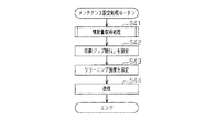
・クリーニング強度を、ホスト装置HC側で設定してもよい。この場合、ホスト装置H
Cの制御装置CNTは、以下に示すメンテナンス設定処理ルーチン(図11参照)を実行
する。このメンテナンス設定処理ルーチンは、プリンター11へ送信した印刷データに基
づいた印刷、すなわち1回の印刷ジョブが終了したタイミングで実行することが好ましい
。
The cleaning intensity may be set on the host device HC side. In this case, the host device H
The C control device CNT executes a maintenance setting process routine (see FIG. 11) shown below. This maintenance setting processing routine is preferably executed at the timing when printing based on the print data transmitted to the
すなわち、図11に示すように、始めにステップS41では、制御装置CNTは、今回
の印刷ジョブでの各インクの噴射量Vを取得する噴射量取得処理を行う。具体的には、制
御装置CNTは、プリンター11側に噴射量Vに関する情報を要求する要求指示を送信す
る。すると、プリンター11のコントローラー86は、今回の印刷ジョブ時に算出した各
インクの噴射量Vに関する情報を制御装置CNTに送信する。その結果、制御装置CNT
は、各インクの噴射量Vを取得する。
That is, as shown in FIG. 11, first, in step S41, the control device CNT performs an ejection amount acquisition process for acquiring the ejection amount V of each ink in the current print job. Specifically, the control device CNT transmits a request instruction for requesting information regarding the ejection amount V to the
Obtains the ejection amount V of each ink.
次のステップS42では、制御装置CNTは、取得した噴射量Vに応じた印刷ジョブ数
Njをインク毎に設定する。なお、印刷ジョブ数Njは、一例として、噴射量Vが多いほ
ど小さな値に設定される。
In the next step S42, the control device CNT sets the number of print jobs Nj corresponding to the acquired ejection amount V for each ink. Note that the number of print jobs Nj is set to a smaller value as the ejection amount V is larger as an example.
次のステップS43では、制御装置CNTは、設定した印刷ジョブ数Njに応じたクリ
ーニング強度をインク毎に設定する(クリーニング条件設定ステップ)。なお、クリーニ
ング強度は、一例として、印刷ジョブ数Njが大きい値であるほど強めに設定される。
In the next step S43, the control device CNT sets the cleaning strength corresponding to the set print job number Nj for each ink (cleaning condition setting step). As an example, the cleaning intensity is set to be stronger as the number of print jobs Nj is larger.
次のステップS44では、制御装置CNTは、ステップS42,S43で設定した印刷
ジョブ数Nj及びクリーニング強度に関する情報をプリンター11側に送信する(送信ス
テップ)。その後、制御装置CNTは、メンテナンス設定処理ルーチンを終了する。
In the next step S44, the control device CNT transmits information on the number of print jobs Nj and the cleaning intensity set in steps S42 and S43 to the
このようにホスト装置HC側で印刷ジョブ数Nj及びクリーニング強度が設定される場
合、プリンター11のコントローラー86が実行する検査要求フラグ設定処理ルーチンで
は、ステップS15,S16の各処理を省略してもよい。
As described above, when the print job number Nj and the cleaning strength are set on the host device HC side, the processing in steps S15 and S16 may be omitted in the inspection request flag setting processing routine executed by the
この場合、プリンター11では、ノズル検査は、ホスト装置HC側で設定された印刷ジ
ョブ数Nj、すなわち実行頻度Frで実行される。そして、ノズル検査によって不良ノズ
ルが検出された場合には、ホスト装置HC側で設定されたクリーニング強度の吸引クリー
ニングが実行される。そのため、無駄に消費される時間やインクの量を低減できる可能性
が高くなる。すなわち、効率よく吸引クリーニングを実行することができる。
In this case, in the
さらに、上記実施形態及び各変形例から把握される技術的思想を以下に記載する。
(イ)取得された印刷データに基づき印刷媒体に印刷処理を行う印刷装置であって、
流体を噴射するノズルを有する印刷手段と、
前記印刷手段における流体噴射不良のノズルの有無を検査するノズル検査手段と、
圧力の付与によって前記ノズルから流体を排出させるクリーニングを行うクリーニング
手段と、
前記ノズル検査手段によるノズル検査の実行頻度に応じて、クリーニングの条件を設定
するクリーニング条件設定手段と、
前記ノズル検査によって流体噴射不良のノズルが検出された場合に、前記クリーニング
条件設定手段によって設定されたクリーニングの条件に基づき前記クリーニング手段を制
御する制御手段と、を備えることを特徴とする印刷装置。
Furthermore, the technical idea grasped | ascertained from the said embodiment and each modification is described below.
(A) A printing apparatus that performs printing processing on a print medium based on acquired print data,
Printing means having nozzles for ejecting fluid;
Nozzle inspection means for inspecting the presence or absence of nozzles with poor fluid ejection in the printing means;
Cleaning means for performing cleaning to discharge fluid from the nozzle by applying pressure;
Cleaning condition setting means for setting cleaning conditions according to the frequency of nozzle inspection performed by the nozzle inspection means;
And a control unit that controls the cleaning unit based on a cleaning condition set by the cleaning condition setting unit when a nozzle having a fluid ejection failure is detected by the nozzle inspection.
この構成によれば、請求項1に係る発明と同様の効果を得ることができる。
According to this configuration, the same effect as that of the invention according to
11…流体噴射装置としてのプリンター、42…流体噴射手段としての印刷ヘッド、4
3…ノズル、45,45A,45B,45C,45D,45E,45F…ノズル群、60
…クリーニング手段としてのメンテナンス装置、64…ノズル検査手段としてのノズル検
査装置、92…制御手段としての主制御部、95…噴射量取得手段としての噴射量取得部
、97…検査頻度設定手段としての検査頻度設定部、98…クリーニング条件設定手段と
してのクリーニング条件設定部、CNT…制御装置、Fr…実行頻度、V…噴射量。
DESCRIPTION OF
3 ... Nozzle, 45, 45A, 45B, 45C, 45D, 45E, 45F ... Nozzle group, 60
... Maintenance apparatus as cleaning means, 64 ... Nozzle inspection apparatus as nozzle inspection means, 92 ... Main control section as control means, 95 ... Injection amount acquisition section as injection amount acquisition means, 97 ... Inspection frequency setting means Inspection frequency setting section, 98... Cleaning condition setting section as cleaning condition setting means, CNT... Control device, Fr... Execution frequency, V.
Claims (6)
該流体噴射手段における流体噴射不良のノズルの有無を検査するノズル検査を行うノズ
ル検査手段と、
圧力の付与によって前記ノズルから流体を排出させるクリーニングを行うクリーニング
手段と、
前記ノズル検査手段によるノズル検査の実行頻度に応じて、クリーニングの条件を設定
するクリーニング条件設定手段と、
前記ノズル検査によって流体噴射不良のノズルが検出された場合に、前記クリーニング
条件設定手段によって設定されたクリーニングの条件に基づき前記クリーニング手段を制
御する制御手段と、を備えることを特徴とする流体噴射装置。 Fluid ejecting means having a nozzle for ejecting fluid;
Nozzle inspection means for performing a nozzle inspection for inspecting the presence or absence of a nozzle with poor fluid ejection in the fluid ejection means;
Cleaning means for performing cleaning to discharge fluid from the nozzle by applying pressure;
Cleaning condition setting means for setting cleaning conditions according to the frequency of nozzle inspection performed by the nozzle inspection means;
A fluid ejecting apparatus comprising: a control unit configured to control the cleaning unit based on a cleaning condition set by the cleaning condition setting unit when a nozzle having a fluid ejection failure is detected by the nozzle inspection. .
査によって検出された前記流体噴射不良のノズルに作用する吸引力が大きくなるように、
クリーニングの条件を設定することを特徴とする請求項1に記載の流体噴射装置。 The cleaning condition setting means is configured such that the lower the frequency of nozzle inspection, the greater the suction force acting on the fluid ejection defective nozzle detected by the nozzle inspection.
The fluid ejecting apparatus according to claim 1, wherein a cleaning condition is set.
前記噴射量取得手段によって取得された流体の噴射量が多いほど、前記ノズル検査の実
行頻度を高く設定する検査頻度設定手段と、をさらに備え、
前記制御手段は、前記検査頻度設定手段によって設定された実行頻度に基づき前記ノズ
ル検査手段を制御することを特徴とする請求項1又は請求項2に記載の流体噴射装置。 An injection amount acquisition means for acquiring an injection amount of fluid from the fluid injection means;
The inspection frequency setting means for setting the nozzle inspection execution frequency higher as the amount of fluid injection acquired by the injection amount acquisition means increases,
The fluid ejecting apparatus according to claim 1, wherein the control unit controls the nozzle inspection unit based on an execution frequency set by the inspection frequency setting unit.
し、
前記噴射量取得手段は前記ノズル群毎に流体の噴射量を取得すると共に、前記検査頻度
設定手段は前記ノズル群毎に前記ノズル検査の実行頻度を設定することを特徴とする請求
項3に記載の流体噴射装置。 The fluid ejecting means has a plurality of nozzle groups constituted by at least one of the nozzles,
The said injection amount acquisition means acquires the injection amount of the fluid for every said nozzle group, and the said inspection frequency setting means sets the execution frequency of the said nozzle test for every said nozzle group. Fluid ejection device.
方法であって、
前記流体噴射手段における流体噴射不良のノズルの有無を検査するノズル検査の実行頻
度に応じて、圧力の付与によって前記ノズルから流体を排出させるクリーニングの条件を
設定するクリーニング条件設定ステップと、
前記ノズル検査によって流体噴射不良のノズルを検出した場合に、前記クリーニング条
件設定ステップで設定した条件に基づき前記クリーニングを行うクリーニングステップと
、を備えることを特徴とする流体噴射装置におけるクリーニング方法。 A cleaning method in a fluid ejecting apparatus including a fluid ejecting unit having a nozzle for ejecting fluid,
A cleaning condition setting step for setting a cleaning condition for discharging the fluid from the nozzle by applying a pressure according to the execution frequency of the nozzle inspection for inspecting the presence or absence of a nozzle with poor fluid ejection in the fluid ejecting means;
A cleaning method for a fluid ejecting apparatus, comprising: a cleaning step that performs the cleaning based on the condition set in the cleaning condition setting step when a nozzle with poor fluid ejection is detected by the nozzle inspection.
ることにより該流体噴射装置を駆動させる制御装置が実行するプログラムであって、
前記制御装置に、
前記流体噴射手段における流体噴射不良のノズルの有無を検査するノズル検査の実行頻
度に応じて、圧力の付与によって前記ノズルから流体を排出させるクリーニングの条件を
設定させるクリーニング条件設定ステップと、
設定したクリーニングの条件に関する情報を前記流体噴射装置に送信させる送信ステッ
プと、を実行させるためのプログラム。 A program executed by a control device that drives a fluid ejecting apparatus by transmitting a command to a fluid ejecting apparatus including a fluid ejecting unit having a nozzle that ejects fluid,
In the control device,
A cleaning condition setting step for setting a cleaning condition for discharging the fluid from the nozzle by applying pressure according to the execution frequency of the nozzle inspection for inspecting the presence or absence of a nozzle with fluid ejection failure in the fluid ejecting means;
A program for causing the fluid ejecting apparatus to transmit information relating to the set cleaning condition.
Priority Applications (1)
| Application Number | Priority Date | Filing Date | Title |
|---|---|---|---|
| JP2010162535A JP2012024928A (en) | 2010-07-20 | 2010-07-20 | Fluid ejection device, cleaning method in fluid ejection device and program |
Applications Claiming Priority (1)
| Application Number | Priority Date | Filing Date | Title |
|---|---|---|---|
| JP2010162535A JP2012024928A (en) | 2010-07-20 | 2010-07-20 | Fluid ejection device, cleaning method in fluid ejection device and program |
Publications (1)
| Publication Number | Publication Date |
|---|---|
| JP2012024928A true JP2012024928A (en) | 2012-02-09 |
Family
ID=45778480
Family Applications (1)
| Application Number | Title | Priority Date | Filing Date |
|---|---|---|---|
| JP2010162535A Withdrawn JP2012024928A (en) | 2010-07-20 | 2010-07-20 | Fluid ejection device, cleaning method in fluid ejection device and program |
Country Status (1)
| Country | Link |
|---|---|
| JP (1) | JP2012024928A (en) |
Cited By (3)
| Publication number | Priority date | Publication date | Assignee | Title |
|---|---|---|---|---|
| JP2016120494A (en) * | 2016-02-18 | 2016-07-07 | 芝浦メカトロニクス株式会社 | Coating liquid coating device |
| JP2018176468A (en) * | 2017-04-06 | 2018-11-15 | 京セラドキュメントソリューションズ株式会社 | Ink jet recording device |
| US11413872B2 (en) * | 2019-10-11 | 2022-08-16 | Kyocera Document Solutions Inc. | Inkjet recording apparatus for recording images by ejecting ink on recording media |
-
2010
- 2010-07-20 JP JP2010162535A patent/JP2012024928A/en not_active Withdrawn
Cited By (3)
| Publication number | Priority date | Publication date | Assignee | Title |
|---|---|---|---|---|
| JP2016120494A (en) * | 2016-02-18 | 2016-07-07 | 芝浦メカトロニクス株式会社 | Coating liquid coating device |
| JP2018176468A (en) * | 2017-04-06 | 2018-11-15 | 京セラドキュメントソリューションズ株式会社 | Ink jet recording device |
| US11413872B2 (en) * | 2019-10-11 | 2022-08-16 | Kyocera Document Solutions Inc. | Inkjet recording apparatus for recording images by ejecting ink on recording media |
Similar Documents
| Publication | Publication Date | Title |
|---|---|---|
| JP5879862B2 (en) | Printing apparatus and printing method | |
| CN102189827B (en) | Recording device and recording method | |
| JP5724234B2 (en) | Print data generation apparatus and print data generation method | |
| US9211743B2 (en) | Droplet discharge device and droplet discharge method | |
| JP2019155597A (en) | Liquid injection device and maintenance method for liquid injection device | |
| JP2012024928A (en) | Fluid ejection device, cleaning method in fluid ejection device and program | |
| US9022511B2 (en) | Recording apparatus and image recording method | |
| JP2010274442A (en) | Recording apparatus and recording apparatus control method | |
| JP5621346B2 (en) | Printing apparatus and printing method | |
| JP2012020518A (en) | Printing device, and method of controlling preparation operation in the same | |
| JP5750841B2 (en) | Printing device | |
| JP2011067964A (en) | Liquid ejecting apparatus, and liquid ejecting method | |
| JP5756593B2 (en) | Liquid ejector | |
| JP3514235B2 (en) | Ink jet recording apparatus and ink droplet ejection inspection method | |
| JP2010105310A (en) | Liquid jet device | |
| JP5609154B2 (en) | Recording device and recording material remaining amount management method | |
| JP2012020517A (en) | Printing device, and method of controlling preparation operation in the same | |
| JP7427913B2 (en) | Liquid injection system, maintenance method of liquid injection system | |
| JP2010058417A (en) | Ejection inspecting device, fluid ejecting apparatus equipped with the same and ejection inspecting method | |
| JP5861357B2 (en) | Liquid ejector | |
| JP2012192567A (en) | Maintenance device, maintenance method and liquid ejecting apparatus | |
| JP6662279B2 (en) | Printhead recovery system, ink jet printing apparatus including the same, and printhead recovery method | |
| JP2024134008A (en) | LIQUID DISCHARGE APPARATUS AND LIQUID DISCHARGE METHOD | |
| JP2012179780A (en) | Maintenance method, and liquid ejection device | |
| JP2014237322A (en) | Liquid ejecting apparatus |
Legal Events
| Date | Code | Title | Description |
|---|---|---|---|
| A300 | Withdrawal of application because of no request for examination |
Free format text: JAPANESE INTERMEDIATE CODE: A300 Effective date: 20131001 |