JP2012020517A - Printing device, and method of controlling preparation operation in the same - Google Patents
Printing device, and method of controlling preparation operation in the same Download PDFInfo
- Publication number
- JP2012020517A JP2012020517A JP2010160866A JP2010160866A JP2012020517A JP 2012020517 A JP2012020517 A JP 2012020517A JP 2010160866 A JP2010160866 A JP 2010160866A JP 2010160866 A JP2010160866 A JP 2010160866A JP 2012020517 A JP2012020517 A JP 2012020517A
- Authority
- JP
- Japan
- Prior art keywords
- printing
- time
- flushing
- carriage
- unit
- Prior art date
- Legal status (The legal status is an assumption and is not a legal conclusion. Google has not performed a legal analysis and makes no representation as to the accuracy of the status listed.)
- Withdrawn
Links
Images


Landscapes
- Ink Jet (AREA)
Abstract
Description
本発明は、印刷手段の印刷能力を確保又は検査するための準備動作を行う印刷装置及び印刷装置における準備動作制御方法に関する。 The present invention relates to a printing apparatus that performs a preparation operation for ensuring or inspecting the printing capability of a printing unit, and a preparation operation control method in the printing apparatus.
例えば特許文献1には、プリンター(印刷装置)を制御する制御部が、記録ヘッド(印刷手段)を記録媒体から外れた位置へ移動させて記録ヘッドからインクを吐出させるフラッシング動作を所定時間毎に実行させる構成が開示されている。また、記録媒体の排出時には、搬送モーターの動作により記録媒体を排出する排出動作中に所定時間(フラッシング時間)が経過する場合にのみ、排出動作の開始前にフラッシング動作を実行させ、一方、排出動作中にフラッシング時間を超えない場合は、排出動作のみを行う構成となっていた。
For example, in
このように排出動作時に限らず、印刷中に何らかの理由で印刷ヘッドを有するキャリッジ(印刷手段)に、次回の印刷を伴う移動(走査)を開始するまでに待機時間が発生した場合は、キャリッジがフラッシング位置へ移動してフラッシングを行うようになっていた。例えば紙送り量が多く、次回の移動を開始するまでの待機時間が一定時間を超えた場合、キャリッジはその待機位置からフラッシング位置へ移動してフラッシング動作を行うことになる。 In this way, not only during the discharging operation, if a waiting time occurs until the carriage (printing means) having the print head for some reason during printing before starting the movement (scanning) with the next printing, the carriage The flashing is performed by moving to the flushing position. For example, when the paper feed amount is large and the standby time until the next movement starts exceeds a certain time, the carriage moves from the standby position to the flushing position and performs the flushing operation.
また、特許文献2には、プリンターが、特定事象から一定時間以上の時間が経過したことを認識した場合、印刷ヘッド(つまり印刷ヘッドを有するキャリッジ)を印刷領域から調整領域へ送る。そして、印刷ヘッドは、調整領域においてレーザー光を用いたノズルのインク滴の吐出検査(ドット抜け検査)を行い、印刷領域へ戻る復路上のフラッシング位置でフラッシングを行う構成が開示されている。このように印刷中には、印刷ヘッドの印刷能力を確保又は検査する目的で、印刷能力(インク吐出能力)を確保するフラッシング動作や、印刷能力の有無を検査するノズル検査などの準備動作が行われる。 Further, in Patent Document 2, when the printer recognizes that a certain time or more has elapsed since the specific event, the printer sends the print head (that is, the carriage having the print head) from the print area to the adjustment area. A configuration is disclosed in which the print head performs an ink droplet ejection test (dot missing test) using laser light in the adjustment region, and performs flushing at the flushing position on the return path to the print region. Thus, during printing, for the purpose of ensuring or inspecting the printing capability of the print head, preparatory operations such as a flushing operation to ensure printing capability (ink ejection capability) and a nozzle inspection to inspect for the presence of printing capability are performed. Is called.
このように、従来のプリンターでは、印刷媒体の紙送り量が多いなどの理由で、キャリッジに印刷中の所定タイミングから所定時間を超える待機時間が発生すると、キャリッジがフラッシング位置へ移動してフラッシングを行うようになっていた。この所定タイミングは、計時を開始するタイミングであるので、以下、計時タイミングと呼び、所定時間は、フラッシングを行うために必要な時間の条件であるので、以下、フラッシング必要条件時間と呼ぶ。 As described above, in the conventional printer, when a waiting time exceeding a predetermined time from a predetermined timing during printing on the carriage occurs due to a large paper feed amount of the printing medium, the carriage moves to the flushing position and the flushing is performed. I was supposed to do it. Since this predetermined timing is a timing at which time measurement is started, it is hereinafter referred to as a time measurement timing, and since the predetermined time is a time condition necessary for performing flushing, it is hereinafter referred to as a flushing necessary condition time.
ところで、図12に示すように、印刷ヘッドHを有するキャリッジCRは、非印刷時の待機位置であるホームポジションHPが位置するホーム(Home)側と、主走査方向Xにホーム側と反対側のフル(Full)側との間で、主走査方向Xに複数回の走査(パス)を繰り返すことにより1パス毎に印刷を行う。図12に示すように、今回(N回目)の印刷(n)を終えて停止したキャリッジCRは、今回(N回目)の紙送り動作が行われている間は待機し、次回(N+1回目)のパスを開始するタイミングになると、次回のパスの移動を開始する。このとき、図12に示すように、今回の印刷(n)位置と次回の印刷(n+1)位置までの紙送り長が比較的長い場合、キャリッジCRの実際の待機時間T(待機開始からの経過時間)がフラッシング必要条件時間Tfcを超えた(T>Tfc)時点で、キャリッジCRはホーム側のフラッシング位置FP(例えばホームポジションHP)へ移動してキャップ等の受容器にフラッシングを行う。 By the way, as shown in FIG. 12, the carriage CR having the print head H is located on the side opposite to the home side in the main scanning direction X and the home side HP where the home position HP, which is a standby position during non-printing, is located. Printing is performed for each pass by repeating a plurality of scans (passes) in the main scanning direction X with the full side. As shown in FIG. 12, the carriage CR that has stopped after the current (Nth) printing (n) is on standby while the current (Nth) paper feeding operation is being performed, and the next (N + 1) th time. When it is time to start the next path, the movement of the next path is started. At this time, as shown in FIG. 12, when the paper feed length from the current printing (n) position to the next printing (n + 1) position is relatively long, the actual waiting time T of the carriage CR (elapsed time from the start of waiting). When the time (time) exceeds the flushing requirement time Tfc (T> Tfc), the carriage CR moves to the home-side flushing position FP (for example, the home position HP) and flushes the receptacle such as the cap.
例えば図12のように、キャリッジCRがフル側で待機していた場合、その待機時間Tがフラッシング必要条件時間Tfcを超えると(T>Tfc)、キャリッジCRはホーム側のフラッシング位置FPへ移動してフラッシングを行う。そして、フラッシングを終えると、キャリッジCRは再び元のフル側へ戻って、フル側の次回の印刷(n+1)開始位置から移動を開始して次回の印刷(n+1)を行う。 For example, as shown in FIG. 12, when the carriage CR is waiting on the full side, if the waiting time T exceeds the flushing requirement time Tfc (T> Tfc), the carriage CR moves to the home flushing position FP. To flush. When the flushing is finished, the carriage CR returns to the original full side again, starts moving from the start position of the next printing (n + 1) on the full side, and performs the next printing (n + 1).
このとき、N回目のパスを終えてフル側で停止したキャリッジCRが、ホーム側へ移動してフラッシングを行い、その後、再び元の位置へ復帰するまでの総所要時間Ttfは、計時タイミングからの時間では、次のようになる。すなわち、総所要時間Ttfは、フラッシング必要条件時間Tfcと、フル側の待機位置からフラッシング位置FPまでのキャリッジCRの移動に要するキャリッジ移動時間Tfhと、フラッシング動作に要するフラッシング動作時間Tfと、フラッシング位置FPからフル側の元の位置(次回の印刷(n+1)開始位置)へキャリッジCRが戻るまでに要するキャリッジ移動時間Thfとの和で表される(Ttf=Tfc+Tfh+Tf+Thf)。この総所要時間Tt fが、今回の紙送りに要する紙送り所要時間Tpfを超えると、紙送り動作が終了しているにも拘わらず、キャリッジCRがフル側の元の位置に戻っておらず、次回の印刷開始時期が遅延することになる。この次回の印刷開始時期の遅延は、印刷のスループットの低下をもたらすという問題があった。このように待機時間がフラッシング必要条件時間Tfc(準備動作必要条件時間)を超えた時点でキャリッジCRが移動を開始してフラッシング(準備動作)を行う構成であると、紙送りが終わっているにも拘わらずキャリッジCRが次回の印刷開始位置に戻っておらず、これが原因で印刷スループットが低下するという問題があった。 At this time, the carriage CR that has stopped on the full side after completing the Nth pass moves to the home side, performs flushing, and then returns to the original position again. The total required time Ttf from the timing is In time it looks like this: That is, the total required time Ttf includes the flushing necessary condition time Tfc, the carriage movement time Tfh required to move the carriage CR from the full standby position to the flushing position FP, the flushing operation time Tf required for the flushing operation, and the flushing position. This is expressed as the sum of the carriage movement time Thf required until the carriage CR returns from the FP to the original position on the full side (next printing (n + 1) start position) (Ttf = Tfc + Tfh + Tf + Thf). When the total required time Tt f exceeds the required paper feed time Tpf required for the current paper feed, the carriage CR has not returned to the original position on the full side even though the paper feed operation has been completed. The next print start time is delayed. This delay in the next printing start time has a problem of causing a reduction in printing throughput. In this way, when the waiting time exceeds the necessary flushing condition time Tfc (preparation operation necessary condition time), the carriage CR starts moving and performs flushing (preparation operation). Nevertheless, the carriage CR has not returned to the next print start position, which has caused a problem that the print throughput is reduced.
本発明は、上記課題に鑑みてなされたものであり、その目的は、印刷中に行われる印刷能力の確保又は検査のための準備動作を効率よく行って、印刷スループットの低下を抑えることができる印刷装置及び印刷装置における準備動作制御方法を提供することにある。 The present invention has been made in view of the above problems, and the object thereof is to efficiently perform a preparatory operation for ensuring printing capability or performing inspection during printing, thereby suppressing a decrease in printing throughput. It is an object to provide a printing apparatus and a preparation operation control method in the printing apparatus.
上記目的を達成するために、本発明は、印刷データを取得する取得手段と、印刷媒体に対する相対的な移動を伴って印刷データに基づく印刷を行う印刷手段と、前記印刷手段の印刷能力を確保又は検査するための準備動作に用いられる準備手段と、前記印刷手段が次の印刷を開始するまでの待機時間を予測し、当該待機時間が第1の設定時間より長くなるか否かを判断する判断手段と、前記待機時間が前記第1の設定時間より長くなると判断した場合は、前記準備動作を行うべき準備動作位置への印刷を伴わない相対移動を開始するまでの待ち時間として設定された第2の設定時間を経過する前に、前記印刷手段の前記準備動作位置への相対移動を開始させるとともに、当該相対移動の後に前記準備動作を行わせ、一方、前記待機時間が前記第1の設定時間より長くならないと判断した場合には、少なくとも前記第2の設定時間を経過する前は、前記印刷手段の前記準備動作位置への相対移動を開始させない制御手段と、を備えたことを要旨とする。なお、印刷手段の印刷を伴う相対移動方向と、印刷手段の準備動作のための相対移動方向は、必ずしも同一である必要はない。例えば印刷が印刷手段の移動により実現されるシリアル式の印刷装置の場合は、前記各方向が同一になる場合が多い。一方、印刷時の相対移動が印刷媒体の搬送により実現され、準備動作時の相対移動が印刷手段の移動により実現される構成を採用した場合のライン式及びページ式の印刷装置の場合は、前記各方向が異なる構成もとりうる。もちろん、これらの構成は一例であってこれに限定されるものではない。 In order to achieve the above object, the present invention ensures an acquisition unit that acquires print data, a printing unit that performs printing based on print data with relative movement with respect to a print medium, and a printing capability of the printing unit. Alternatively, the preparation means used for the preparation operation for inspection and the waiting time until the printing means starts the next printing are predicted, and it is determined whether or not the waiting time is longer than the first set time. When the determination means determines that the standby time is longer than the first set time, it is set as a waiting time until the relative movement without printing to the preparation operation position where the preparation operation should be performed is started. Before the second set time elapses, the printing unit starts relative movement to the preparation operation position, and the preparation operation is performed after the relative movement, while the waiting time is And a control unit that does not start relative movement of the printing unit to the preparation operation position at least before the second set time elapses when it is determined that it is not longer than the set time of 1. Is the gist. Note that the relative movement direction accompanying printing of the printing unit and the relative movement direction for the preparation operation of the printing unit are not necessarily the same. For example, in the case of a serial printing apparatus in which printing is realized by movement of printing means, the directions are often the same. On the other hand, in the case of a line-type and page-type printing apparatus adopting a configuration in which the relative movement during printing is realized by transporting the print medium and the relative movement during preparation operation is realized by moving the printing unit, A configuration in which each direction is different may be employed. Of course, these configurations are merely examples, and the present invention is not limited thereto.
この発明によれば、印刷手段の次の印刷を開始するまでの待機時間(予測待機時間)が第1の設定時間より長くなると判断した場合は、印刷手段の準備動作位置への相対移動を開始するまでの待ち時間として設定された第2の設定時間を経過する前に、印刷手段の準備動作位置への相対移動を開始させる。また、待機時間が第1の設定時間より長くならないと判断した場合は、少なくとも第2の設定時間を経過する前は、印刷手段の準備動作位置への相対移動を開始させない。よって、印刷中の準備動作を、印刷の遅延をなるべく小さく抑えつつ適切に行うことができる。 According to this invention, when it is determined that the standby time (predicted standby time) until the next printing of the printing unit is started is longer than the first set time, the relative movement of the printing unit to the preparation operation position is started. The relative movement of the printing unit to the preparatory operation position is started before the second set time set as the waiting time until the time elapses. If it is determined that the standby time is not longer than the first set time, the relative movement of the printing unit to the preparation operation position is not started at least before the second set time has elapsed. Therefore, the preparatory operation during printing can be performed appropriately while minimizing the delay in printing.
本発明の印刷装置においては、前記制御手段は、前記印刷手段の前記準備動作位置への相対移動の後に行うべき前記準備動作の開始時期を、次の印刷の開始タイミングに合わせて調整する。 In the printing apparatus of the present invention, the control unit adjusts the start timing of the preparation operation to be performed after the relative movement of the printing unit to the preparation operation position in accordance with the start timing of the next printing.
この発明によれば、印刷手段の準備動作位置への相対移動の後に行われる準備動作の開始時期が、次の印刷の開始タイミングに合わせて調整されるので、待機時間が比較的長い場合でも、準備動作が次の印刷の開始時期に比較的近い時期に行われ、より印刷能力の高い状態で次の印刷を行うことができる。 According to the present invention, since the start timing of the preparation operation performed after the relative movement of the printing unit to the preparation operation position is adjusted in accordance with the start timing of the next printing, even when the standby time is relatively long, The preparation operation is performed at a time relatively close to the start time of the next printing, and the next printing can be performed with a higher printing capability.
本発明の印刷装置においては、前記制御手段は、前記印刷手段の実際の待機時間を計時し、前記判断手段により予測の前記待機時間が前記第1の設定時間より長くならないと判断された場合は、前記実際の待機時間が前記第2の設定時間を超えた場合に、前記印刷手段の前記準備動作位置への相対移動を開始させる。 In the printing apparatus according to the aspect of the invention, the control unit measures an actual standby time of the printing unit, and when the determination unit determines that the predicted standby time is not longer than the first set time. When the actual standby time exceeds the second set time, the relative movement of the printing unit to the preparation operation position is started.
この発明によれば、待機時間が第1の設定時間より長くならないと判断(予測)した結果、印刷手段の準備動作位置への相対移動を開始させなかった場合でも、その予測に反して、実際の待機時間が第1の設定時間を超えた場合に準備動作を行うことができる。 According to the present invention, even if the relative movement to the preparatory operation position of the printing unit is not started as a result of determining (predicting) that the standby time is not longer than the first set time, contrary to the prediction, When the waiting time exceeds the first set time, the preparatory operation can be performed.
本発明の印刷装置においては、前記第1の設定時間は、前記第2の設定時間に略等しい。この発明によれば、予測待機時間が準備動作位置への相対移動を開始するまでの待ち時間として設定された第2の設定時間(=第1の設定時間)より長くなると判断した場合は、この第2の設定時間を経過する前に、印刷手段の準備動作位置への相対移動を開始させる。また、予測待機時間が第2の設定時間(=第1の設定時間)より長くならないと判断した場合は、少なくとも第2の設定時間を経過する前は、印刷手段の準備動作位置への相対移動を開始させない。よって、印刷中の準備動作を、印刷の遅延をなるべく小さく抑えつつ適切に行うことができる。 In the printing apparatus of the present invention, the first set time is substantially equal to the second set time. According to the present invention, when it is determined that the predicted standby time is longer than the second set time (= first set time) set as the waiting time until the relative movement to the preparation operation position starts, Before the second set time elapses, the relative movement of the printing means to the preparation operation position is started. If it is determined that the predicted standby time is not longer than the second set time (= first set time), at least before the second set time has elapsed, the relative movement of the printing unit to the preparation operation position is performed. Does not start. Therefore, the preparatory operation during printing can be performed appropriately while minimizing the delay in printing.
本発明の印刷装置においては、前記判断手段が予測する前記待機時間は、前記印刷手段が次の印刷を開始する前に前記準備動作位置へ相対移動して前記準備動作を行った場合における次の印刷を開始するまでの待機時間であり、前記第1の設定時間は、前記予測の待機時間が、次の印刷の開始時期の遅延を伴うことなく当該次の印刷を開始しうる最大許容待機時間である。 In the printing apparatus according to the aspect of the invention, the waiting time predicted by the determination unit is the next time when the preparation unit performs the preparation operation by moving relative to the preparation operation position before the printing unit starts the next printing. This is a waiting time until printing is started, and the first set time is the maximum allowable waiting time during which the predicted waiting time can start the next printing without a delay in the start time of the next printing. It is.
この発明によれば、判断手段は、印刷手段が次の印刷を開始する前に準備動作を行った場合における次の印刷を開始するまでの待機時間を予測する。この予測した待機時間(以下「予測待機時間」という。)が、次の印刷の開始時期の遅延を伴うことなく開始しうる最大許容待機時間(第1の設定時間)より長くなると判断した場合は、印刷手段の準備動作位置への相対移動を開始するまでの待ち時間として設定された第2の設定時間を経過する前に、印刷手段の準備動作位置への相対移動を開始させる。また、予測待機時間が第1の設定時間より長くならないと判断した場合は、少なくとも第2の設定時間を経過する前は、印刷手段の準備動作位置への相対移動を開始させない。よって、印刷中の準備動作を,印刷の遅延をなるべく小さく抑えつつ適切に行うことができる。 According to the present invention, the determination unit predicts a waiting time until the next printing is started when the printing unit performs a preparatory operation before starting the next printing. When it is determined that the predicted standby time (hereinafter referred to as “predicted standby time”) is longer than the maximum allowable standby time (first set time) that can be started without delay of the next printing start time. The relative movement of the printing unit to the preparation operation position is started before the second set time set as the waiting time until the relative movement of the printing unit to the preparation operation position starts. When it is determined that the predicted standby time is not longer than the first set time, the relative movement of the printing unit to the preparation operation position is not started at least before the second set time has elapsed. Therefore, it is possible to appropriately perform the preparatory operation during printing while minimizing the delay in printing.
前記準備動作は前記印刷手段の印刷能力回復力又は検査能力の違いに応じた複数種用意され、前記制御手段は、前記複数種用意された前記準備動作のうち前記待機時間又は残り印刷量に応じた一つを選択し、前記印刷手段に当該選択した一つの準備動作を行わせる。 A plurality of types of the preparatory operations are prepared in accordance with the difference in the printing capability recovery capability or the inspection capability of the printing unit, and the control unit is responsive to the waiting time or the remaining printing amount of the plurality of types of the preparatory operations. One is selected, and the printing unit is caused to perform the selected one preparation operation.
この発明によれば、制御手段は、待機時間又は残り印刷量に応じた一つの準備動作を選択し、印刷手段にその選択した準備動作を行わせる。よって、待機時間又は残り印刷量に応じた適切な準備動作を行って、残りの印刷を適切に行うことができる。 According to the present invention, the control unit selects one preparation operation corresponding to the standby time or the remaining printing amount, and causes the printing unit to perform the selected preparation operation. Accordingly, it is possible to appropriately perform the remaining printing by performing an appropriate preparation operation according to the standby time or the remaining printing amount.
本発明の印刷装置では、前記印刷手段は前記印刷媒体に対する相対的な往復運動を行って印刷を行い、前記準備動作位置は、前記印刷手段が前記往復運動を行う経路の両側のうち第1の側に設定されており、前記印刷手段に前記準備動作位置への相対移動が前記経路における前記第1の側とは反対側の第2の側から前記第1の側へ向かって行われる場合には、前記準備動作位置で前記準備動作を行った後に前記印刷手段が前記第1の側から次の印刷を開始しうるように印刷データを変更する変更手段を更に備えた。 In the printing apparatus according to the aspect of the invention, the printing unit performs printing by performing a reciprocating motion relative to the printing medium, and the preparatory operation position is the first of both sides of the path on which the printing unit performs the reciprocating motion. And when the relative movement to the preparatory operation position is performed from the second side opposite to the first side in the path from the second side toward the first side. Further includes changing means for changing the print data so that the printing means can start the next printing from the first side after performing the preparation operation at the preparation operation position.
この発明によれば、印刷手段が準備動作のための相対移動をその相対移動の経路における第2の側から第1の側へ向かって行う場合は、変更手段により、印刷手段が第1の側で準備動作を行った後に当該第1の側から印刷を開始しうるように印刷データが変更される。よって、印刷手段は準備動作のために経路の反対側である第1の側へ移動しても、第2の側へ戻ることなく、第1の側から次の印刷を伴う相対移動を開始することができる。この結果、印刷のスループットを向上できる。 According to the present invention, when the printing unit performs the relative movement for the preparatory operation from the second side to the first side in the path of the relative movement, the printing unit is moved to the first side by the changing unit. The print data is changed so that printing can be started from the first side after the preparation operation is performed. Therefore, even if the printing unit moves to the first side which is the opposite side of the path for the preparation operation, the printing unit starts relative movement with the next printing from the first side without returning to the second side. be able to. As a result, printing throughput can be improved.
本発明は、印刷媒体に対する相対的な移動を伴って印刷データに基づく印刷を行う印刷手段と、前記印刷手段の印刷能力を確保又は検査するための準備動作に用いられる準備手段とを備えた印刷装置における準備動作制御方法であって、印刷手段の印刷を伴う次の相対移動を開始するまでの待機時間を予測し、当該予測した待機時間が第1の設定時間より長くなるか否かを判断する判断手順と、前記待機時間が前記第1の設定時間より長くなると判断した場合は、前記準備動作のための相対移動を開始するまでの待ち時間として設定された第2の設定時間を経過する前に、前記印刷手段に前記準備動作のための相対移動を開始させ、一方、前記待機時間が前記第1の設定時間より長くならないと判断した場合には、少なくとも前記第2の設定時間を経過する前は、前記印刷手段に前記準備動作のための相対移動を開始させない制御手順と、を備えたことを要旨とする。この発明によれば、上記印刷装置に係る発明と同様の効果を得ることができる。 The present invention includes a printing unit that performs printing based on print data with a relative movement with respect to a print medium, and a printing unit that includes a preparation unit that is used for a preparation operation for securing or inspecting the printing capability of the printing unit. A preparatory operation control method in the apparatus for predicting a standby time until the next relative movement accompanied by printing by a printing unit is started, and determining whether the predicted standby time is longer than a first set time. And determining that the waiting time is longer than the first set time, a second set time set as a waiting time until the relative movement for the preparation operation starts is passed. Before, when the printing means starts relative movement for the preparatory operation, while it is determined that the standby time is not longer than the first set time, at least the second setting Before elapse between shall be summarized in that and a control procedure that does not initiate the relative movement for the preparation operation to the printing unit. According to this invention, it is possible to obtain the same effect as that of the invention relating to the printing apparatus.
以下、本発明を具体化した一実施形態を図1〜図9に基づいて説明する。
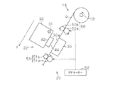
図1(a)は、本実施形態の印刷装置の構成の一例を示す斜視図である共に、図1(b)は、印刷装置の主要部の内部構成の一例を示す斜視図である。図1(a)(b)に示すように、印刷装置11は、印刷媒体の一例としてロール状の印刷用紙(以下、「ロール紙P」ともいう。)に印刷処理を行うシリアルタイプのインクジェット式プリンターである。こうした印刷装置11は、ロール紙Pに対して印刷処理を行う印刷装置本体12と、該印刷装置本体12を重力方向における下方から支持する支持用脚部13とを備えている。
Hereinafter, an embodiment embodying the present invention will be described with reference to FIGS.
FIG. 1A is a perspective view showing an example of the configuration of the printing apparatus of the present embodiment, and FIG. 1B is a perspective view showing an example of the internal configuration of the main part of the printing apparatus. As shown in FIGS. 1A and 1B, a
また、印刷装置本体12の前面側から見て左側には、複数(本実施形態では6つ)のインクカートリッジ14を収容するホルダー部15と、該ホルダー部15をその前面から覆う開閉可能なホルダー用カバー16とが設けられている。各インクカートリッジ14には、互いに種類(例えば、色)の異なるインク(印刷材)がそれぞれ収容されている。また、印刷装置本体12の前面側から見て右側上部には、ユーザーによって操作される操作パネル17が設けられており、該操作パネル17は、液晶画面と各種ボタンとを有している。
Further, on the left side when viewed from the front side of the printing apparatus
印刷装置本体12の上側には、ロール紙Pが収容される媒体収容部18が設けられている。この媒体収容部18内に収容されるロール紙Pは、主走査方向Xに沿って延びる軸部材19に巻かれている。媒体収容部18内において主走査方向Xにおける両側には、軸部材19を回転自在な状態で支持する軸支持部20がそれぞれ設けられている。そして、軸部材19が所定の回転方向(図3で矢印で示す方向)に回転することにより、ロール紙Pは、長尺状の用紙として印刷装置本体12内に送り出される。なお、媒体収容部18の前面側には、該媒体収容部18内に収容されるロール紙Pを覆う取り外し可能な収容部用カバー21が設けられている。
On the upper side of the printing apparatus
印刷装置本体12内には、ロール紙Pにおいて印刷装置本体12内に搬送された部分に対してインクを噴射するインク噴射部22と、該インク噴射部22に向けてロール紙Pを搬送する搬送手段の一例としての搬送装置23(図3参照)とが設けられている。また、印刷装置本体12には、ロール紙Pにおいてインク噴射部22によってインクが付着した部分、即ち印刷が完了した部分が排紙される排紙部24が設けられている。なお、印刷装置本体12は、該印刷装置本体12内を覆うための開閉可能な本体カバー25を有している。
In the printing apparatus
次に、インク噴射部22について説明する。
図2及び図3に示すように、インク噴射部22は、主走査方向X(図2では左右方向)に延びる支持部材30を備えている。この支持部材30は、主走査方向Xにほぼ直交する副走査方向(搬送方向)Yにおいて上流側(媒体収容部18側)のほうが下流側(排紙部24側)よりも上方に位置するように配置されている。すなわち、支持部材30は、水平面に対して斜状をなす支持面30aを有している。こうした支持部材30の支持面30aは、ロール紙Pのうち印刷装置本体12内に搬送された部分を支持する。
Next, the
As shown in FIGS. 2 and 3, the
また、インク噴射部22は、主走査方向Xに延びるガイド軸31を備えており、該ガイド軸31は、支持部材30の支持面30aに対向して配置されている。こうしたガイド軸31は、キャリッジ32を主走査方向Xに沿って往復移動可能な状態で支持している。
Further, the
また、インク噴射部22は、正逆両方向に回転可能なキャリッジモーター(以下、「CRモーター」ともいう。)33と、該CRモーター33から出力された駆動力をキャリッジ32に伝達するキャリッジ駆動部34とを備えている。このキャリッジ駆動部34は、印刷装置本体12の後面において主走査方向Xにおける両端側に回転自在な状態で支持される一対のプーリー35,36を有しており、一方(図2では右側)のプーリー35には、CRモーター33の出力軸(図示略)が動力伝達可能な状態で連結されている。また、一対のプーリー35,36間には、一部がキャリッジ32に連結された無端状のタイミングベルト37が掛装されている。そして、キャリッジ32は、CRモーター33からの駆動力がキャリッジ駆動部34を介して伝達されることにより、主走査方向Xに沿ってガイド軸31にガイドされながら移動する。
The
また、キャリッジ32の後面側には、該キャリッジ32の主走査方向Xにおける位置、移動速度及び移動方向を検出するための図4に示すリニアエンコーダー38が設けられている。このリニアエンコーダー38は、図4に示すように、主走査方向Xに延びる被検出用テープ39と、キャリッジ32に支持される検出部40とを備えている。被検出用テープ39は、印刷装置本体12に移動不能な状態で支持されると共に、主走査方向Xに沿って等間隔に形成される多数のスリット39aを有している。検出部40は、主走査方向Xにおいて互いに異なる位置に配置される複数(一例として2つ)のセンサー(図示略)を有している。そして、検出部40の各センサーからは、キャリッジ32の移動距離に比例するパルス数で、かつキャリッジ32の移動速度に反比例するパルス周期を有するパルス状の検出信号が制御回路60(図4参照)にそれぞれ出力される。
Further, on the rear surface side of the
また、キャリッジ32上には、各インクカートリッジ14から供給された各種インクを個別に一時的に貯留する複数(本実施形態では6つ)のサブタンク(図示略)が設けられている。これら各サブタンクには、インク供給装置41(図4参照)の駆動によって個別対応するインクカートリッジ14からインクがそれぞれ供給される。
On the
また、図2に示すように、キャリッジ32において支持部材30に対向する側には、印刷ヘッド42が設けられている。この印刷ヘッド42には、サブタンクからインクが供給される複数(図2では6つのみ図示)のノズル43と、各ノズル43に個別対応する図示しない複数の駆動素子(一例として、圧電素子)とが設けられている。各ノズル43は、印刷ヘッド42において支持部材30に対向するノズル形成面44にそれぞれ開口している。そして、ノズル43からは、サブタンクから供給されたインクが、駆動素子の駆動によって支持部材30に向けて噴射(供給)される。したがって、本実施形態では、印刷ヘッド42及びキャリッジ32により、ロール紙Pにおいてインク噴射部22に搬送された部分にインクを付着させる印刷手段が構成される。
As shown in FIG. 2, a
キャリッジ32の主走査方向Xにおける一方側(図2では右側)には、非印刷時におけるキャリッジ32の待機位置となるホームポジションHPが設定されている。本実施形態では、キャリッジ32が走査される経路(主走査経路)の両側のうち、ホームポジションHP側をホーム(Home)側(一方側)、その反対側をフル(Full)側(他方側)とそれぞれ呼ぶこととする。印刷時には、キャリッジ32はホーム側からフル側への往動と、フル側からホーム側への復動とを交互に行ってロール紙Pへの印刷を行う。印刷方式としては、キャリッジ32の往動と復動との双方向で印刷を行う双方向印刷方式と、キャリッジ32のどちらか一方向のみの移動時に印刷を行い他方向への移動時には印刷せず空走(空走査)する一方向印刷方式とが採用されている。例えば印刷品質より印刷速度を優先するドラフト印刷モードでは双方向印刷方式が設定され、印刷速度より印刷品質を優先する高精細印刷モードでは一方向印刷が設定される。
On one side (right side in FIG. 2) of the
また、図2に示すように、キャリッジ32がホームポジションHPに位置したときのその直下には、印刷ヘッド42の各種メンテナンスを行うためのメンテナンス装置45が配置されている。このメンテナンス装置45には、ホームポジションHPに位置する印刷ヘッド42のノズル43が開口するノズル形成面44(図2では下面)に対して接離する方向(図2では上下方向)に移動可能な有底略筒状のキャップ46と、キャップ46を昇降移動させる昇降機構47とが設けられている。キャップ46は、ホームポジションHPに位置する印刷ヘッド42の各ノズル43から噴射又は吸引排出されたインク(「廃インク」ともいう。)を受容可能とされている。
As shown in FIG. 2, a
キャリッジ32が主走査方向Xに往復運動しつつロール紙Pにインク滴を噴射して画像等の印刷を施す印刷中において、フラッシング実行条件が成立すると、キャリッジ32はホームポジションHPへ移動してキャップ46内へ印刷とは関係のないインク滴を噴射(つまり空吐出)するフラッシングを行う。
When the
印刷ヘッド42がキャッピングなされていない印刷中は、ノズル43内のインクが徐々に増粘し、ノズル43の目詰まりが心配される。この種のノズル目詰まりを防止するため、本実施形態では、印刷中にフラッシング実行条件が成立すると、キャリッジ32をホームポジションHPへ移動させてフラッシングを行う。フラッシング実行条件には2種類ある。1つは、キャリッジ32が1パスを終えて停止した際に前回のフラッシングが終了したタイミングである計時タイミングから計時した時間が一定時間以上(フラッシング間隔時間Tfi)となっていたときである。2つめは、キャリッジ32が1パスを終えて停止したタイミングである計時タイミングから次のパスを開始するタイミングになるまでロール紙Pの紙送りを待つと予測される待機時間(以下「紙送待機予測時間Tw」という。)が、フラッシング必要条件時間Tfc(第1の設定時間)を超えると予測されたときである。これらのうち一方の条件が成立したときは、キャリッジ32をホームポジションHPへ移動させてフラッシングを行わせる。なお、シリアル式の印刷装置11である本例では、キャリッジ32の次パスの開始が、印刷手段の次の印刷の開始に相当する。
During printing in which the
本実施形態では、このフラッシングが、印刷ヘッド42の能力を確保するための準備動作に相当する。そして、この準備動作に供されるメンテナンス装置45(このうち特にキャップ46)が準備手段に相当する。また、本実施形態では、フラッシング必要条件時間Tfcが、第1の設定時間と第2の設定時間とを兼ねる例であるが、第1の設定時間と第2の設定時間とを異ならせても構わない。なお、キャリッジ32がホームポジションHPでフラッシングを行う本例では、ホームポジションHPをフラッシング位置FPと呼ぶ場合もある。
In the present embodiment, this flushing corresponds to a preparatory operation for ensuring the capability of the
また、メンテナンス装置45は、印刷ヘッド42の全ノズルのうち目詰まり等の不良ノズルの有無を検査する図2に示すノズル検査部48を備えている。本実施形態では、ノズル検査は、印刷ヘッド42の検査対象ノズルから帯電したインク滴(以下「帯電インク滴」ともいう。)をキャップ46に向かって所定回数(1〜10回の範囲内の値)噴射して行われる。ノズル検査部48は、検査対象ノズルから噴射された帯電インク滴がキャップ46に着弾するまでの過程においてキャップ46側の電位変化を検出し、その検出結果を基に不良ノズルの有無を検査する検査方式を採用する。この検査方式では、キャップ46側の電位変化が検出されれば検査対象ノズルがインク滴を噴射可能な正常ノズルと判定し、一方、キャップ46側の電位変化が検出されなければ、検査対象ノズルがインク滴を噴射できない不良ノズルと判定する。
Further, the
本実施形態では、このノズル検査は、所要時間がフラッシング所要時間に比べ比較的長いので、印刷開始時のみ行うようにしているが、フラッシングと同様に印刷中に行ってもよい。この場合、このノズル検査が、印刷ヘッド42の印刷能力を検査するための準備動作に相当する。そして、この準備動作に供されるノズル検査部48が準備手段に相当する。また、第1の設定時間は、フラッシングのときのフラッシング必要条件時間Tfcと同じとし、フラッシングとノズル検査を、特許文献2のように1回のキャリッジ移動で一緒に行ってもよい。もちろん、ノズル検査用の必要条件時間Tncを個別に設定してもよい。
In the present embodiment, this nozzle inspection is performed only at the start of printing because the required time is relatively longer than the required time for flushing. However, it may be performed during printing as in the case of flushing. In this case, this nozzle inspection corresponds to a preparatory operation for inspecting the printing capability of the
また、メンテナンス装置45はクリーニング用の吸引ポンプ49(図4に示す)を備えている。キャップ46を印刷ヘッド42のノズル形成面44に当接させた状態で吸引ポンプ49を駆動することによりキャップ46とノズル形成面44とに囲まれた空間を負圧とし、その負圧によってノズル43から強制的にインクを吸引排出させることにより、ノズル43のクリーニングが行われる。例えばノズル検査で不良ノズルが検出された場合はクリーニングが行われる。このようにメンテナンス装置45は、キャッピング、フラッシング、ノズル検査及びクリーニングなどに使用される。
The
次に、搬送装置23について説明する。図3に示すように、搬送装置23は、副走査方向Yに沿ってロール紙Pを搬送する装置である。こうした搬送装置23は、副走査方向Yにおいて支持部材30の上流側(図3では右斜め上方であって、媒体収容部18側)に配置される給紙ローラー対50と、副走査方向Yにおいて支持部材30の下流側(図3では左斜め下方であって、排紙部24側)に配置される排紙ローラー対51とを備えている。給紙ローラー対50及び排紙ローラー対51は、紙送りモーター(以下、「PFモーター52」という)から伝達される駆動力によって回転する駆動ローラー50a,51aと、該駆動ローラー50a,51aの回転に伴い従動回転する従動ローラー50b,51bとでそれぞれ構成されている。そして、PFモーター52から伝達される駆動力によって各駆動ローラー50a,51aが図3で示す矢印方向に回転することにより、各ローラー対50,51に挟持されるロール紙Pは、副走査方向Yにおいて排紙部24側に紙送り(搬送)される。なお、媒体収容部18内において軸部材19が所定の方向(図3の矢印が示す方向)に回転することにより、ロール紙Pが送り出される。
Next, the
次に、印刷装置11の電気的構成を図4に基づいて説明する。図4に示すように、印刷装置11の制御回路60(コントローラー)は、インターフェイス61を介してホスト装置HCとの間で印刷ジョブデータD1などの各種情報を送受信可能な状態で接続されている。また、制御回路60のインターフェイス61には、ユーザーによる操作パネル17の操作結果に関する操作情報が入力される。
Next, the electrical configuration of the
ホスト装置HCには、印刷ジョブデータD1を生成するための図4に示すプリンタードライバーPDが備えられている。このプリンタードライバーPDは、ホスト装置HCのCPU(図示略)とプログラムとにより構築されている。印刷ジョブデータD1は、コマンドと、ロール紙Pに印刷すべき画像に関する画像データとを含んでいる。プリンタードライバーPDは、画像データの解像度を印刷装置11の印刷解像度に変換し、変換後の画像データに対して色変換処理を行う。続いて、プリンタードライバーPDは、色変換処理済みの画像データに対してハーフトーン処理(階調数変換処理)を行う。
The host device HC is provided with the printer driver PD shown in FIG. 4 for generating the print job data D1. The printer driver PD is constructed by a CPU (not shown) of the host device HC and a program. The print job data D1 includes a command and image data relating to an image to be printed on the roll paper P. The printer driver PD converts the resolution of the image data to the printing resolution of the
そして、プリンタードライバーPDは、上記各種処理が施された画像データと印刷制御用のコマンド等とを含む印刷ジョブデータD1を印刷装置11側に出力(転送)する。このとき、印刷ジョブデータD1は、キャリッジ32の1走査分(1パス分)ずつ転送される。この1パス分の印刷ジョブデータD1は、主走査(1パス)及び副走査(紙送り)1回分ずつのコマンドと、1主走査分の画像データ(以下、「分割画像データD2」ともいう。)とを含んでいる。
Then, the printer driver PD outputs (transfers) print job data D1 including the image data subjected to the above-described various processes and a print control command to the
次に、印刷装置11の制御回路60について説明する。制御回路60は、コンピューター62(マイクロコンピューター)(図4では一点鎖線で囲まれた部分)を備えている。コンピューター62は、CPU63、ASIC64((Application Specific IC(特定用途向けIC))、ROM65、不揮発性メモリー66及びRAM67を備え、これらはバス68を介して互いに接続されている。このコンピューター62は、各種ドライバー69,70,71,72に電気的に接続されている。そして、コンピューター62は、PF用ドライバー69を介してPFモーター52を制御すると共に、CR用ドライバー70を介してCRモーター33を制御する。また、コンピューター62は、ヘッド用ドライバー71を介して印刷ヘッド42(具体的には、印刷ヘッド42内の各駆動素子)を制御すると共に、インク供給用ドライバー72を介してインク供給装置41を制御する。
Next, the
さらにコンピューター62は、ノズル検査用電圧印加回路73を介してノズル検査部48を構成するキャップ46内のインク滴受容部に導通する導電体(例えば金属メッシュ)(図示略)と、印刷ヘッド42のノズル形成面44(特に金属製ノズルプレート)とに電気的に接続されている。そして、少なくともノズル検査時には、コンピューター62はノズル検査用電圧印加回路73を介してキャップ46の導電体に例えばプラス電位を印加するとともに、ノズル形成面44に例えばマイナス電位を印加する。印刷ヘッド42の検査対象ノズルから負に帯電したインク滴を噴射したときにキャップ46の電位変化を示す検出信号は検出回路74を介してコンピューター62に入力される。ここで、検出回路74は、詳しくは、キャップ46の導電体から入力した検出信号を積分する積分回路と、その積分回路から出力された信号を反転増幅する反転増幅回路と、その反転増幅回路から出力されたアナログ信号をデジタル信号に変換するA/D変換回路などを備えている。
Further, the
ROM65には、各種制御プログラム及び各種データなどが記憶されている。不揮発性メモリー66には、ファームウェアプログラムを始めとする各種プログラム及び印刷処理に必要な各種データなどが記憶されている。具体的には、不揮発性メモリー66は、キャリッジ32の1パス終了時点に次パスの走査を開始するまでに比較的長い待機時間が発生したときに、フラッシングを行うか否かの判定基準として使用される前述のフラッシング必要条件時間Tfcなどを記憶するフラッシング時間情報記憶部66aを有している。
The
RAM67には、CPU63によって実行されるプログラムデータ、CPU63による演算結果及び処理結果である各種データ、及びASIC64で処理された各種データなどが一時記憶される。このRAM67は、受信バッファー67a、中間バッファー67b及び出力バッファー67cを有している。
The RAM 67 temporarily stores program data executed by the
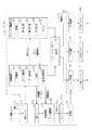
次に、本実施形態のコンピューター62について説明する。図5はコンピューター62の機能構成を示すブロック図である。なお、図5は、ロール紙Pへの印刷中に行われるフラッシング制御に関する機能部分を中心に図示したものであり、ノズル検査などその他の機能部分などについては図示を省略している。
Next, the
図5に示すように、コンピューター62は、ハードウェア及びソフトウェアのうち少なくとも一方により実現される機能部分として、印刷制御部75、フラッシング制御部76、ジョブコントロール部77、画像処理部78、転送部79及びシーケンス制御部80を備えている。印刷制御部75は、主に印刷制御を司り、その内部に、主制御部81、コマンド解析部82、データ解析部83、演算部84及び紙送り長取得部85を備えている。また、フラッシング制御部76は、主にフラッシング制御を司り、その内部に、演算部86、第1判定部87、第2判定部88、第3判定部89及びタイマー90を備えている。印刷制御部75とフラッシング制御部76は、制御上それぞれの下位層に相当するジョブコントロール部77へ、キャリッジ系、紙送り系、印刷ヘッド系の各種指示を出力する。
As shown in FIG. 5, the
ジョブコントロール部77は、上位層である各制御部75,76からの指示を調整する機能をもち、その内部に要求部91を備えている。要求部91は、ジョブコントロール部77が上位層から受け付けた指示内容に応じた各種の要求(キャリッジ起動要求、紙送り開始要求、インク噴射開始要求、フラッシング要求等)を、優先順序に従って、制御上その下位層に相当するシーケンス制御部80へ出力する。 The job control unit 77 has a function of adjusting instructions from the control units 75 and 76, which are upper layers, and includes a request unit 91 therein. The request unit 91 controls various requests (carriage activation request, paper feed start request, ink ejection start request, flushing request, etc.) according to the instruction received from the upper layer by the job control unit 77 according to the priority order. The data is output to the sequence control unit 80 corresponding to the lower layer.
シーケンス制御部80は、受け付けた要求に応じた動作を適切な順序及びタイミングで行わせるシーケンス制御を司り、その内部に、PF制御部92、CR制御部93及びヘッド制御部94を備えている。PF制御部92は、要求された内容に応じてPF用ドライバー69を介してPFモーター52をシーケンス制御し、給送動作、紙送り動作、排紙動作などを行わせる。CR制御部93は、要求された内容に応じてCR用ドライバー70を介してCRモーター33をシーケンス制御し、印刷動作やフラッシング動作の際のキャリッジ動作を行わせる。また、ヘッド制御部94は、要求された内容に応じてヘッド用ドライバー71を介して印刷ヘッド42のノズル43毎の駆動素子を駆動制御し、要求された印刷動作やフラッシング動作のためノズル43からインク滴を噴射させる。
The sequence control unit 80 performs sequence control for performing operations according to the received request in an appropriate order and timing, and includes a PF control unit 92, a
受信バッファー67aには、ホスト装置HCから受信した印刷ジョブデータD1等の受信データが格納される。印刷ジョブデータD1には、1ページ分の画像データを1パス分ずつ分割した1つの分割画像データD2と、1パス分の印刷及び紙送りを指示するコマンドとが含まれる。また、印刷装置11が1つのジョブで最初に受信する印刷ジョブデータD1には、ユーザーがホスト装置HCに入力設定した印刷条件情報(印刷モード、用紙種、用紙サイズ等)が含まれる。印刷制御部75は、印刷モードから印刷方式(バンド印刷やマイクロウィーブ印刷等)を解析し、分割画像データD2の各ドット(印刷画素)の印刷方式に応じたノズル割付け方法を決定する。印刷制御部75は、受信バッファー67aから読み出した印刷ジョブデータD1中のコマンドを解析し、その解析結果に基づく指示をジョブコントロール部77へ出力するとともに、分割画像データD2を中間バッファー67bに格納する。
Reception data such as print job data D1 received from the host device HC is stored in the
画像処理部78は、中間バッファー67bに格納された分割画像データD2を展開する。このとき、画像処理部78は、印刷方式に合わせてドットデータのノズルへの割り付けを行うとともに、割り付けた各ドットデータをキャリッジ移動方向に応じた噴射順序に合わせた順番に配列してヘッド制御用の印刷データD3(ヘッド制御データ)を生成する。この印刷データD3は、出力バッファー67cに格納される。こうして画像処理部78は、キャリッジ移動方向に応じたインク噴射順序の順番にドットデータが配列された印刷データD3を構築する。
The
転送部79は、出力バッファー67cに格納された印刷データD3を1パス分ずつヘッド制御部94へ転送する。ヘッド制御部94は印刷データD3に基づきヘッド用ドライバー71を介してノズル毎の駆動素子を駆動制御し、ノズル43からインク滴を噴射させることによりロール紙Pに印刷画像を形成する。印刷データD3は、キャリッジ32の移動方向(走査方向)に応じた順番にドットが配列されて構築されるので、キャリッジ32の移動が往動か復動かに依らず、印刷ヘッド42により1パス分ずつの画像が正しく印刷される。
The
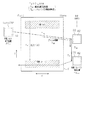
ここで、フラッシング制御部76がキャリッジ32を制御して行われるフラッシング制御について、図6を用いて説明する。図6は、フラッシング時のキャリッジ32の動作を説明する模式図である。なお、図6では、副走査方向Yへのロール紙Pの紙送りを、キャリッジ32の反Y方向への相対移動で示している。従来(図12)は、フラッシング必要条件時間Tfcの経過を待ってからキャリッジを起動していたが、本実施形態では、次のパスを開始するまでの待機時間の予測値を紙送待機予測時間Twとして計算する。そして、フラッシング制御部76は、紙送待機予測時間Twがフラッシング必要条件時間Tfc(第1の設定時間)を超えると、フラッシング必要条件時間Tfc(第2の設定時間)の経過を待たず、直ちにキャリッジ32を、準備動作位置の一例であるフラッシング位置FP(本例ではホームポジションHP)へ向かって起動させる。
Here, the flushing control performed by the flushing control unit 76 by controlling the
シリアルプリンターである印刷装置11では、キャリッジ32が複数パスの印刷を施すことによりロール紙Pに1ページ分の印刷画像が印刷される。例えば往路方向へ移動してNパス目の印刷(n)を終えたキャリッジ32は、図6に示すように、フル側の停止位置PTn(印刷(n)終了位置)で停止する。本例では、この停止に先立ちN回目の紙送り(n)が開始される。この紙送り(n)によって、ロール紙Pは、N回目の印刷(n)位置からN+1回目のパスで印刷予定の印刷(n+1)位置まで、副走査方向Yへ紙送り長Lpfだけ搬送される。このとき、キャリッジ32は、フル側の停止位置PTnで、ロール紙Pが次回のパスを開始可能な位置に搬送されるまで待機することになる。
In the
図6において、フル側の待機位置PTnから移動を開始したキャリッジ32が、フラッシング位置FPでのフラッシングを終了するまでの総所要時間(以下「フラッシング総所要時間Ttf」ともいう。)は、キャリッジ移動時間Tthと、フラッシング待機時間Tfwと、フラッシング動作時間Tfとの和で示される(Ttf=Tth+Tfw+Tf)。ここで、キャリッジ移動時間Tthとは、キャリッジ32が待機位置PTnからフラッシング位置FPへ到達するまでの所要時間を示す。フラッシング待機時間Tfwとは、フラッシング動作の開始時期が、フラッシング動作終了直後に丁度N+1回目のパスを開始できるタイミングになるように設定される。つまり、キャリッジ32が次回のパスの移動を開始する直前にフラッシング動作が終了するように時間調整のための待ち時間が、フラッシング待機時間Tfwである。このため、フラッシング待機時間Tfwは設定されない(つまりTfw=0)場合もある。なお、本実施形態では、フラッシング必要条件時間Tfcは、例えば500〜3000ミリ秒の範囲内の所定値に設定されている。
In FIG. 6, the total time required for the
また、双方向印刷モードにおいて、フラッシングを終えたホームポジションHPから次回のパスを開始できるように、既にフル側→ホーム側のキャリッジ移動方向(復路方向)のパスを前提として構築された印刷データD3(ヘッド制御データ)を、ホーム側→フル側のキャリッジ移動方向(復路方向)のパスで印刷(インク滴噴射)が可能になるように再構築する。図5に示すように、画像処理部78は、変更手段の一例としてのデータ再構築部95を備えている。フラッシング制御部76は、フラッシング時にキャリッジ32をフル側→ホーム側へ移動させた場合、印刷制御部75にデータ再構築要求を出力する。この要求を受付けた印刷制御部75は画像処理部78に再構築指令を出力する。この再構築指令を受け付けた画像処理部78では、データ再構築部95が、既にフル側→ホーム側へのキャリッジ移動方向に合わせたドット配列順序で構築された次回(N+1回目)のパス用の印刷データD3を、ホーム側→フル側へのキャリッジ移動方向(往路方向)に合わせたドット配列順序に再構築する。図6に示すように、このデータ再構築は、キャリッジ32が待機位置PTnから移動を開始してフラッシング動作を終了するまでの間に終了する。つまり、キャリッジ32が待機位置PTnから移動を開始してから、時間(Tfh+Tfw+Tf)が経過するまでに、印刷データD3の再構築は終了する。このため、データ再構築所要時間Tdrは、フラッシング総所要時間Ttfには含まれない。
Further, in the bidirectional printing mode, the print data D3 that has already been constructed on the premise of the full-side → home-side carriage movement direction (return direction) so that the next pass can be started from the home position HP after flushing. (Head control data) is reconstructed so that printing (ink droplet ejection) is possible in a path in the carriage movement direction (return path direction) from the home side to the full side. As shown in FIG. 5, the
次に、印刷制御部75が行う制御内容及び処理内容を説明する。主制御部81は、印刷制御部75が行う印刷制御の全体を司り、各部82〜85を制御する。コマンド解析部82は、受信バッファー67aから読み出した印刷ジョブデータD1を、コマンドと分割画像データD2とに分ける。そして、コマンドを解析(解釈)し、その解析結果に応じた要求をジョブコントロール部77へ出力する。この結果、印刷制御部75は、ジョブコントロール部77に対してコマンド解析部82の解析結果に応じた、給送指示、印刷指示、紙送り指示、排紙指示などを含む各種の指示を行う。
Next, control contents and processing contents performed by the print control unit 75 will be described. The
データ解析部83は、分割画像データD2を解析し、キャリッジ32が主走査方向に移動して印刷ヘッド42により1パス分の印刷を行うときのインク噴射開始位置(ファーストドット位置Fnともいう)と、インク噴射終了位置(ラストドット位置Lnともいう)とを取得する。ここで、ファーストドット位置Fnとラストドット位置Lnの添え字「n」は、N回目のパスであることを指す。また、データ解析部83は、キャリッジ32が主走査方向Xに1パス分の移動を行うときのキャリッジ32の起動位置PSnと停止位置PTnとを取得する。
The
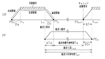
図7は、印刷動作と紙送り動作の関係を示すタイミングチャートを示す。図7において上段がキャリッジ32の速度プロファイルを示すグラフであり、このグラフにおいて横軸がキャリッジ位置x、縦軸がキャリッジ速度Vとなっている。また、図7において下段が紙送り動作の速度プロファイルを示すグラフであり、このグラフにおいて横軸がロール紙Pの搬送位置、縦軸がロール紙Pの搬送速度となっている。なお、図7では横軸方向の区間におけるキャリッジ移動又は紙送りに要する時間も示している。
FIG. 7 is a timing chart showing the relationship between the printing operation and the paper feeding operation. 7 is a graph showing the speed profile of the
図7上段のグラフに示すように、キャリッジ32の1パス動作(例えばN回目のパス動作)時の速度プロファイルは、キャリッジ32の起動位置PSnから定速領域に達するまでの加速領域と、キャリッジ32が一定速度で移動する定速領域と、キャリッジ32が定速度から減速して停止位置PTnで停止するまでの減速領域とを含む。図7の例では、定速領域においてハッチングを施したインク噴射領域で印刷(インク滴噴射)が行われる。
As shown in the upper graph of FIG. 7, the speed profile during the one-pass operation (for example, the N-th pass operation) of the
演算部84は、データ解析部83が取得したファーストドット位置Fnに加速距離Da(助走距離)をキャリッジ移動方向と反対側に付加して起動位置PSnを演算すると共に、データ解析部83が取得したラストドット位置Lnに減速距離Db(制動距離)をキャリッジ移動方向側に付加して停止位置PTnを演算する(図7参照)。なお、キャリッジ32の加速領域の途中からインク噴射を開始し、減速領域の途中でインク噴射を終了する加減速印刷制御を採用してもよい。
The
紙送り長取得部85は、紙送りコマンドに設定された紙送り長Lpf(搬送長)を取得する。主制御部81は、紙送り長Lpfに応じた搬送速度のPF速度テーブル(図示略)を選択し、これらの紙送り情報と共に紙送り指令をジョブコントロール部77に出力する。これらの紙送り情報は、紙送待機予測時間Twの演算に使用するためにフラッシング制御部76へも送られる。
The paper feed
また、本実施形態では、図7に示すように、印刷動作と紙送り動作をタイミング的に一部重複させるPF・CR重ね合わせ制御を採用する。すなわち、印刷制御部75は、図7に示すように、インク滴の噴射を終了した時点(ラストドット形成時点)で紙送り動作を開始し、次パスのために起動したキャリッジ32がファーストドット形成位置に到達した時点でロール紙Pが停止するタイミングとなるように、紙送り動作終了よりも時間ΔT分早期にキャリッジ32を起動させる。
Further, in the present embodiment, as shown in FIG. 7, PF / CR superposition control in which the printing operation and the paper feeding operation are partially overlapped in timing is adopted. That is, as shown in FIG. 7, the print control unit 75 starts the paper feeding operation at the time when the ejection of ink droplets is completed (the last dot formation time), and the
演算部84は、次パスのキャリッジ起動位置PSn+1からファーストドット位置Fn+1までのCR移動所要時間ΔT(本例では加速所要時間)を計算する。さらに演算部84は、今回の紙送り終了位置PEn(停止位置)から紙送り方向と逆方向へCR移動所要時間ΔT分に相当する搬送量ΔS(搬送距離)を計算し、紙送り終了位置PEnから搬送量ΔSだけ手前の位置を、CR起動要求位置として算出する。搬送量ΔSはジョブコントロール部77へ通知される。ジョブコントロール部77は、N回目の紙送り動作中において紙送り終了位置PEnまでの残り搬送量ΔSrをPFカウンター(図示略)の計数値から把握し、残り搬送量ΔSrが搬送量ΔSに達した時点(つまりキャリッジ32がCR起動要求位置に達した時点)でCR制御部93へキャリッジ起動要求を出力する(図7参照)。なお、PF制御部92は、紙送り開始時にPFカウンター(図示略)に紙送り長Lpfをセットし、この計数値から搬送用のロータリーエンコーダー(図示略)からのエンコーダーパルスの入力数を順次減算することで、このPFカウンターの計数値に基づき残り搬送量ΔSrを管理する。ジョブコントロール部77は、PF制御部92が管理する残り搬送量ΔSrを監視し、残り搬送量ΔSrが搬送量ΔSに達したときに、CR制御部93へキャリッジ起動要求を出力する。
The
CR制御部93は、リニアエンコーダー38からのエンコーダーパルス信号に基づき主走査方向Xにおけるキャリッジ32の位置(以下「キャリッジ位置」と称す。)を計数する。また、CR制御部93は、キャリッジ駆動時にリニアエンコーダー38から入力する2相のエンコーダーパルス信号のうち一方の立ち上がりエッジ検出時に他方のパルスのレベル(HiかLow)を判別し、この判別結果に応じてキャリッジ移動方向を把握する。CR制御部93は、キャリッジ32がホーム位置に配置されたときにリセットしたCRカウンター(図示略)の計数値を、キャリッジ32の往動過程(ホーム→フル方向移動時)においてインクリメントし、復動過程(フル→ホーム方向移動時)においてデクリメントすることで、ホームポジションHPを原点とするキャリッジ位置を管理する。CR制御部93は、キャリッジ32の起動位置PSnからのキャリッジ位置xを監視し、CR速度テーブル(CR速度プロファイルデータ)を参照して各キャリッジ位置xに応じた目標速度に対応する指令値をCR用ドライバー70に出力する。
The
また、ジョブコントロール部77は、1パス分の印刷動作中において、CR用カウンターの計数値からキャリッジ位置(つまり印刷ヘッド42の位置)を監視し、印刷ヘッド42がファーストドット位置Fnに到達するタイミングで、ヘッド制御部94にインク噴射開始要求を出力する。この要求を受け付けたヘッド制御部94は、印刷ヘッド42がファーストドット位置Fnに到達すると、ヘッド用ドライバー71に開始信号を出力してインク滴噴射を開始させる。そして、印刷ヘッド42がラストドット位置Lnに到達すると、ヘッド制御部94はジョブコントロール部77に印刷動作終了の旨を応答する。この応答を受付けたジョブコントロール部77は、PF制御部92に対して紙送り要求を出力する。この要求を受け付けたPF制御部92は、PF用ドライバー69を介してPFモーター52を駆動させることで紙送り動作を開始させる。こうしてN回目のパスにおいてインク滴噴射を終了した時点でN回目の紙送りが開始され、ロール紙Pが停止位置PEnに停止する時点よりも時間ΔTだけ前に、キャリッジ32のN+1回目のパスが起動される。
The job control unit 77 monitors the carriage position (that is, the position of the print head 42) from the count value of the CR counter during the printing operation for one pass, and the timing at which the
また、本実施形態では、キャリッジ32の印刷動作中(移動中)に、スーパーロジカルシークと呼ばれるキャリッジ制御方法を採用する。このキャリッジ制御方法では、今回のラストドット位置Lnから決まる今回の停止位置PTnと、次回のファーストドット位置Fn+1から決まる次回の起動位置PSn+1とを比較し、PTn,PSn+1のうち次回(N+1回目)の加速距離Da(助走距離)が確保される一方を、今回の停止位置に決定する。
In the present embodiment, a carriage control method called superlogical seek is adopted during printing operation (moving) of the
図8は、このキャリッジ制御方法を説明するグラフである。図8における上段のN回目の印刷動作を示すグラフと、中段のN+1回目の印刷動作を示すグラフとを用いて、印刷制御部75が行うスーパーロジカルシークによるキャリッジ制御方法を説明する。 FIG. 8 is a graph for explaining this carriage control method. A carriage control method by super logical seek performed by the print control unit 75 will be described using a graph showing the Nth printing operation in the upper stage in FIG. 8 and a graph showing the N + 1th printing operation in the middle stage.
演算部84は、キャリッジ32がN回目(今回)の主走査を行っている間に、N+1回目(次回)のファーストドット位置Fn+1に、N回目のキャリッジ移動方向側に加速距離Daを付加して、N+1回目のキャリッジ起動位置PSn+1を計算する。そして、主制御部81は、今回のキャリッジ停止位置PTnと、次回のキャリッジ起動位置PSn+1とを比較し、今回のキャリッジ移動方向先方へより遠くに位置する一方を今回の停止位置PTnとして決定する。図8の例のように、N回目のキャリッジ停止位置PTnよりもN+1回目のキャリッジ起動位置PSn+1の方が、N回目のキャリッジ進行方向先方へより遠ければ、N回目の停止位置PTn(図8上段グラフにおける2点鎖線矢印終点)に替えて、(N+1回目)のキャリッジ起動位置PSn+1を、N回目(今回)の新たな停止位置PTn(図8上段グラフにおける実線矢印終点)として再設定する。
The
このようにキャリッジ32の1パス終了時の停止位置PTnは、パス毎に変化する。よって、キャリッジ32がフル側の停止位置PTn(待機位置)からフラッシング位置FPまでの移動に要するキャリッジ移動時間Tfhは、その時々の待機位置に応じて変化する。
Thus, the stop position PTn at the end of one pass of the
また、図8における下段のグラフに示すように、フラッシング位置FP(つまりホームポジションHP)から起動したキャリッジ32が、次回(N+1回目)のファーストドット位置Fn+1に到達するまでに要するCR移動所要時間ΔT(図7におけるΔTに相当)は、フラッシング位置FPから次回(N+1回目)のファーストドット位置Fn+1までの距離に応じて変化する。このため、CR移動所要時間ΔTに対応する残り搬送量ΔSr(図7を参照)も変化し、紙送り動作中のキャリッジ起動タイミングが、次回のファーストドット位置Fn+1に応じて変化することになる。
Further, as shown in the lower graph in FIG. 8, the CR movement required for the
次にフラッシング制御部76の制御及び処理の詳細を説明する。フラッシング制御部76は、印刷中に所定条件が満たされた際に行うべきフラッシングを制御する。フラッシング制御部76は、前述のように、図5に示す演算部86、第1判定部87、第2判定部88、第3判定部89及びタイマー90を備えている。
Next, details of the control and processing of the flushing control unit 76 will be described. The flushing control unit 76 controls flushing to be performed when a predetermined condition is satisfied during printing. As described above, the flushing control unit 76 includes the calculation unit 86, the
演算部86は、紙送待機予測時間Twを演算する。詳しくは、演算部86は、今回(N回目)のパスの移動方向に応じてキャリッジ32がフル側又はホーム側に停止すると、印刷制御部75から、現在実行中の今回(N回目)の紙送りにおける紙送り長Lpfと、今回(N回目)の紙送りのために使用中のPF速度テーブルとを取得する。そして、演算部86は、紙送り長Lpfの紙送り動作のために次回(N+1回目)のパスでキャリッジ32を起動するまでの待機時間の予測値である紙送待機予測時間Twを演算する。図7に示すように、キャリッジ32が今回(N回目)のパスで停止した時点では、ラストドット位置Lnから停止位置PTnで停止するまでの所要時間ΔTdを経過している。演算部84は、紙送り長LpfとPF速度テーブル(PF速度プロファイルデータ)とに基づき、紙送り動作の所要時間である紙送り所要時間Tpf(図7参照)をまず演算する。そして、演算部84は、紙送り所要時間Tpfから所要時間ΔTd,ΔTを差し引くことにより、紙送待機予測時間Twを、式 Tw=Tpf−ΔT−ΔTdにより計算する(図7を参照)。
The computing unit 86 computes the estimated paper feed standby time Tw. Specifically, when the
第1判定部87は、紙送待機予測時間Twがフラッシング必要条件時間Tfcを超えた(Tw>Tfcが成立した)か否かを判定する。フラッシング制御部76は、条件Tw>Tfcが成立した場合、ジョブコントロール部77にフラッシングを指示すると共に、印刷制御部75にフラッシング用のドットデータの生成を要求する。ジョブコントロール部77は、フラッシング指示を受け付けると、CR制御部93にキャリッジ32をフラッシング位置FPへ移動させるようにCRモーター33を制御する。また、印刷制御部75は、フラッシング用のドットデータを不揮発性メモリー66の所定記憶領域から読み出して中間バッファー67bに格納する。そして、画像処理部78はフラッシング用のドットデータを基にフラッシング用の噴射データを生成し、出力バッファー67cに格納する。なお、本実施形態では、演算部86及び第1判定部87により、判断手段が構成される。
The
第2判定部88は、キャリッジ32のフラッシング位置FPへの移動方向が、フル側からホーム側へ向かう方向であるか否かを判定する。第2判定部88は、例えば移動開始前(つまり待機中)のキャリッジ位置を記憶し、それがフル側であれば、その移動方向がフル側からホーム側へ向かう方向であると判定する。一方、移動開始前のキャリッジ位置がホーム側であれば、その移動方向がフル側からホーム側へ向かう方向ではないと判定する。このように第2判定部88は、フラッシング時にキャリッジ32がその移動経路の両側のうちフル側(第2の側)からホーム側(第1の側)へ移動したか否かを判断する。
The
タイマー90は、本実施形態では、キャリッジ32が1パスを終えて停止する度に計時を開始し、停止中(待機中)の経過時間Tを計時する。つまり、タイマー90は、今回(N回目)のパスを終えたキャリッジ32が停止位置PTnで停止してから次回のパスのために起動するまでの経過時間T(つまり実際の待機時間T)を計時する。第3判定部89は、キャリッジ32の実際の待機時間Tがフラッシング必要条件時間Tfcを超えたか否かを判定する。
In the present embodiment, the
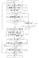
次に、本実施形態のコンピューター62が実行する印刷処理ルーチンについて、図7に示すフローチャートに基づき説明する。
さて、印刷装置11では、ホスト装置HCからの印刷ジョブデータD1の受信が開始されたタイミングで、印刷処理ルーチンが実行される。すると、初めにコンピューター62は、印刷開始処理を行う。具体的には、コンピューター62は、ロール紙Pの先端をインク噴射部22内に進入させるべくPFモーター52を制御する。また、コンピューター62(コマンド解析部82)は、受信バッファー67aに一時格納された印刷ジョブデータD1に含まれるヘッダー情報を解析する。ここでは、コマンド解析部82は、ホスト装置HCからジョブの最初に送信される印刷ジョブデータD1中のヘッダー情報から印刷モード(高精細モード/ドラフトモード)や印刷方式(双方向印刷/一方向印刷)、印刷色(カラー/グレイスケール)、用紙サイズなどの印刷条件情報を取得する。この後、コンピューター62は図9のフローチャートに従って印刷処理を実行する。なお、以下のフローチャートでは、双方向印刷モードの例で説明する。
Next, a print processing routine executed by the
In the
まずステップS10では、印刷データを生成する。すなわち、コマンド解析部82が印刷ジョブデータD1中のコマンドを解析して紙送り長Lpf等を取得すると共に、データ解析部83が分割画像データD2のデータ解析を行ってドット位置Fn,Lnを取得する。さらに画像処理部78が分割画像データD2に展開処理やノズル割付処理等の所定の処理を施して印刷データD3を生成する。なお、出力バッファー67cに複数パス分の印刷データD3を格納できた状態で、印刷動作を開始する構成となっており、N回目の印刷時におけるS10では、1回分以上先のパス(例えばN+1回目のパス)用の印刷データD3を生成する。これは印刷データD3が生成できていないために次回のキャリッジ32の起動開始時期が遅延する事態を回避するためである。
First, in step S10, print data is generated. That is, the
ステップS20では、印刷処理を行う。詳しくはCRモーター33を駆動してキャリッジ32を1走査(1パス動作)させると共に、N回目用の印刷データD3を基にヘッド用ドライバー71を介してノズル毎の駆動素子を駆動させることにより、1走査の途中でノズル43からインク滴を噴射させることで、1パス分の印刷を行う。
In step S20, a printing process is performed. Specifically, the
ステップS30では、紙送り処理を行う。ジョブコントロール部77はN回目のインク噴射を終了したタイミングでPF制御部92に紙送り要求を出力する。この紙送り要求を受け付けたPF制御部92はPFモーター52の駆動を開始させると共に、指定のPF速度テーブルを参照してPFモーター52を速度制御することにより、ロール紙Pを紙送り長Lpfだけ紙送りする動作を開始する。このとき、紙送り要求は、図7に示すように、今回(N回目)のラストドット位置Lnに到達した直後に出力され、紙送り動作が印刷動作中のラストドット形成直後に開始されるPF・CR重ね合わせ制御が行われる。その後、紙送り開始時点より時間ΔTdだけ遅れてキャリッジ32は今回の停止位置PTnに停止する。
In step S30, a paper feed process is performed. The job control unit 77 outputs a paper feed request to the PF control unit 92 at the timing when the Nth ink ejection is completed. Upon receipt of this paper feed request, the PF control unit 92 starts driving the
ステップS40では、紙送りを開始してからキャリッジ32が停止するまでの間に、紙送待機予測時間Twを演算する。但し、この演算は、紙送り動作開始前に行ったり、演算所要時間が無視できる程度に短ければキャリッジ32が停止した直後に行ったりしてもよい。そして、この演算は次のように行う。まず演算部86は、図7に示す紙送り所要時間Tpfを、紙送り長LpfとPF速度テーブル(PF速度プロファイルデータ)を参照して計算する。次に、紙送り開始時点(本例ではラストドットLn形成終了時点)からキャリッジ32が今回(N回目)の停止位置PTnで停止するまでのCR移動所要時間ΔTdを計算し、さらに次回(N+1回目)のパスの起動位置PSn+1からファーストドット位置Fn+1に到達するまでのキャリッジ32の移動所要時間であるCR移動所要時間ΔTを計算する。そして、紙送待機予測時間Twを、式 Tw=Tpf−ΔTd−ΔTにより計算する。
In step S40, a predicted paper feed standby time Tw is calculated between the start of paper feed and the stop of the
ステップS50では、紙送待機予測時間Twがフラッシング必要条件時間Tfcを超えるか否かを判定する。詳しくは、この判定は第1判定部87が行う。Tw>Tfcが成立した場合はステップS60に進み、Tw>Tfcが不成立の場合はステップS120に進む。
In step S50, it is determined whether or not the estimated paper feed standby time Tw exceeds the flushing necessary condition time Tfc. Specifically, this determination is performed by the
ステップS60では、キャリッジ32をホーム側のフラッシング位置へ移動させる。この場合、今回のパスでキャリッジ32がフル側の停止位置PTnで停止(待機)していた場合、図6に示すように、キャリッジ32はフル側の停止位置PTn(印刷(n)終了位置)からホーム側のフラッシング位置FPへ移動することになる。また、今回のパスでキャリッジ32がホーム側の停止位置PTnで停止していた場合、キャリッジ32はホーム側の待機位置から同じホーム側のフラッシング位置へ移動することになる。この場合、キャリッジ32は少し復動方向へ移動するだけで済む。
In step S60, the
ステップS70では、(1)紙送待機予測時間Tw、印刷インク量Viに応じたフラッシング方法を決定すると共に、(2)次パスの印刷開始直前にフラッシングを終了しうるフラッシング開始時期Tstを算出する。 In step S70, (1) a flushing method corresponding to the estimated paper feed standby time Tw and the printing ink amount Vi is determined, and (2) a flushing start timing Tst at which flushing can be completed immediately before starting the next pass printing is calculated. .
フラッシング方法は、紙送待機予測時間Twが長いほど強力なフラッシングを行う。フラッシングの強度の調整には、フラッシング回数と、フラッシング1回当たりのインク噴射量(インク噴射量/回)とにより行う。すなわち、紙送待機予測時間Twが長いほどその間にインクの増粘が進むので、紙送待機予測時間Twが長いほどフラッシング強度を高くする。また、紙送り終了以後の同一頁内の残り印刷領域の印刷に使用する印刷インク量Viを求め、この印刷インク量Viに応じてフラッシング強度を調整する。印刷インク量Viが多く残り印刷量が多いほどフラッシング強度を高くする。これはフラッシング強度を高くするほどドット抜け発生確率を低くでき、ドット抜け発生確率が同じ条件の下では残り印刷量が多いほどドット抜け発生数が高くなるからである。そして、このドット抜け発生数を極力「0」に抑えられるように、残り印刷量(つまり印刷インク量Vi)が多いほど強力なフラッシングを行うようにしている。 In the flushing method, the stronger the flushing waiting time Tw, the stronger the flushing is performed. The intensity of the flushing is adjusted by the number of times of flushing and the ink ejection amount (ink ejection amount / time) per flushing. In other words, the longer the paper feed standby time Tw is, the more the ink viscosity increases. Therefore, the longer the paper feed standby time Tw is, the higher the flushing strength is. Further, the printing ink amount Vi used for printing the remaining printing area in the same page after the paper feed is completed is obtained, and the flushing intensity is adjusted according to the printing ink amount Vi. As the printing ink amount Vi increases and the remaining printing amount increases, the flushing strength is increased. This is because the higher the flushing strength, the lower the dot drop occurrence probability, and the higher the remaining printing amount, the higher the number of dot drop occurrences under the same dot drop occurrence probability. In order to suppress the number of missing dots to “0” as much as possible, the stronger the flushing is performed as the remaining printing amount (that is, the printing ink amount Vi) increases.
本例では具体的には、紙送待機予測時間Twと印刷インク量Viとの各値の組合せ毎に、フラッシング回数とインク噴射量/回とを対応付けたフラッシング強度決定テーブルが、不揮発性メモリー66に記憶されている。そして、フラッシング制御部76は、算出した紙送待機予測時間Twと印刷インク量Viを基にフラッシング強度決定テーブルを参照して、これらの値Tw,Viに応じた適切なフラッシング強度(フラッシング回数、インク噴射量/回)を決定する。 Specifically, in this example, a flushing intensity determination table that associates the number of times flushing and the amount / time of ink ejection for each combination of values of the estimated paper feed standby time Tw and the printing ink amount Vi is a non-volatile memory. 66. Then, the flushing control unit 76 refers to the flushing strength determination table based on the calculated estimated paper feed standby time Tw and the printing ink amount Vi, and performs an appropriate flushing strength (flushing number, flushing) according to these values Tw and Vi. Ink ejection amount / time) is determined.
また、フラッシング開始時期Tstは次のように計算する。キャリッジ32が今回(N回目)の停止位置PTnで停止してからの経過時間Tはタイマー90が計時しており、この経過時間Tが紙送待機予測時間Twを超えたとき(T>Tw)が、次回(N+1回目)のパスのキャリッジ起動時期となる。この次パスのキャリッジ起動時期よりフラッシング動作時間Tf分だけ早い時期がフラッシング開始時期Tstとなる。よって、演算部86は、このフラッシング開始時期(時間)Tstを、式 Tst=Tw−Tfにより計算する。経過時間Tがこのフラッシング開始時間Tstに達した時点が、フラッシング動作を開始すべきフラッシング開始時期になる。
The flushing start time Tst is calculated as follows. The
次のステップS80では、フラッシング位置へのキャリッジ移動が、フル→ホーム方向への移動であるか否かを判定する。この判定は第2判定部88が行う。フラッシング制御部76は、例えばフラッシング位置への移動を開始する前の待機位置が、ホーム側であるかフル側であるかを示す待機位置情報(例えばフラグ)を、1パス終了毎にRAM67の所定記憶領域に記憶する。第2判定部88は、この待機位置情報を基にフル→ホーム方向への移動であるか否かを判定する。例えば待機位置情報がフル側を示す値「1」であれば、フル→ホーム方向への移動であると判定し、一方、ホーム側を示す値「0」であれば、フル→ホーム方向への移動ではないと判定する。第2判定部88は、肯定判定(フラグ「1」)であればステップS90に進み、否定判定(フラグ「0」)であればステップS100に進む。
In the next step S80, it is determined whether or not the carriage movement to the flushing position is a movement from the full direction to the home direction. This determination is performed by the
ステップS90では、印刷データを、ホーム→フル方向に再構築する。つまり、次パスのキャリッジ移動方向に合わせて、フル→ホーム方向のドット形成順序に構築された印刷データD3を、ホーム→フル方向のドット形成順序となるように再構築する。このデータの再構築の結果、フラッシング位置FPからキャリッジ32を起動して、次回の印刷をホーム側から開始することができるようになる。
In step S90, the print data is reconstructed from home to full. That is, the print data D3 constructed in the dot formation order in the full → home direction in accordance with the carriage movement direction of the next pass is reconstructed so that the dot formation order in the home → full direction is obtained. As a result of the reconstruction of the data, the
ステップS100では、フラッシング開始時期Tstに達したか否かを判断する。すなわち、フラッシング制御部76は、経過時間Tがフラッシング開始時間Tstに達したか否かを判断する。T≧Tstが不成立であれば成立するまで待機し、一方、T≧Tstが成立すればステップS110に進む。 In step S100, it is determined whether or not the flushing start time Tst has been reached. That is, the flushing control unit 76 determines whether or not the elapsed time T has reached the flushing start time Tst. If T ≧ Tst is not established, the process waits until it is established, while if T ≧ Tst is established, the process proceeds to step S110.
ここで、フラッシング開始時期Tstに達する前に、キャリッジ32がフラッシング位置FPに到達しているときは、図6に示すように、フラッシング開始時期Tstに達するまでにフラッシング待機時間Tfwが発生する。一方、フラッシング開始時間Tstに達した後に、キャリッジ32がフラッシング位置FPに到達した場合は、その到達後、直ちにフラッシング動作を開始する。図7に示すフル→ホーム方向へのキャリッジ移動時間Tfhは、パス毎に決まる待機位置PTnに応じて異なり、Tst>Tfhの場合はフラッシング待機時間Tfwが発生するが、Tst≦Tfhの場合はフラッシング待機時間Tfwが発生せず、フラッシング位置FPへの到達後直ぐにフラッシング動作を開始することになる。なお、演算部86がフラッシング待機時間Tfwを計算し、キャリッジ32がフラッシング位置に到達してからの経過時間がフラッシング待機時間Tfwに達した時点で、フラッシングを開始する構成を採用してもよい。フラッシング待機時間Tfwは、例えば式 Tfw=Tst−Tfhにより計算され、Tfw>0の場合はその値をフラッシング待機時間として採用し、Tfw≦0の場合はTfw=0にする。
Here, when the
ステップS110では、決定した方法でフラッシングを実行する。但し、T≧Tstが成立した時点においてキャリッジ32がまだフラッシング位置FPに到達していなかった場合は、その到達を待って直ちにフラッシングを実行する。このS110の処理では、ステップS70で決定したフラッシング方法でフラッシングを実行する。この結果、紙送待機予測時間Twが長いほど、印刷インク量Viが多いほど、フラッシング強度(フラッシング回数、インク噴射量/回)を高くしたフラッシングが行われる。このため、このフラッシング後に行われる同一頁内の残りの印刷でドット抜け発生数を極力「0」に抑えることができる。
In step S110, flushing is executed by the determined method. However, if the
ステップS140では、印刷終了であるか否かを判断する。全てのパスを終えておらず、印刷終了でなければ、ステップS10に戻り、全てのパスを終えるまで、パス毎に同様の処理を繰り返す。 In step S140, it is determined whether printing is finished. If all passes have not been completed and printing has not ended, the process returns to step S10, and the same processing is repeated for each pass until all passes have been completed.
そして、n+1回目におけるステップS20において、次回(N+1回目)のパスの印刷処理を行う。このN+1回目のパスの印刷処理は、再構築された印刷データD3に基づき印刷が行われるので、キャリッジ32がフラッシング位置(ホーム側)から起動しても画像を正しく印刷できる。
In step S20 in the (n + 1) th time, the next (N + 1th) pass printing process is performed. Since the printing process of the (N + 1) th pass is performed based on the reconstructed print data D3, the image can be correctly printed even when the
一方、ステップS50においてTw>Tfcが不成立であった場合は、ステップS120において、タイマー90がキャリッジ32のN回目のパスを終えて停止した時点からの経過時間T(実際の待機時間T)を計測する。そして、ステップS130において、経過時間Tがフラッシング必要条件時間Tfcを超えたか否かを第3判定部89が判定する。T>Tfcが成立した場合には、キャリッジ32をフラッシング位置へ移動させて(S60)、S70〜S90の処理を行った後、フラッシング開始時期Tstに達すればフラッシングを実行させる(S100,S110)。
On the other hand, if Tw> Tfc is not established in step S50, in step S120, an elapsed time T (actual waiting time T) from when the
例えばユーザーが、印刷中に本体カバー25を誤って開けると、安全のために印刷装置11の動作を停止させることがある。このような印刷装置11の停止など何らかの原因で実際の待機時間Tが予測に反してフラッシング必要条件時間Tfcを超えた場合は、フラッシングが行われる。このため、待機時間の予測に反して、実際の待機時間Tがフラッシング必要条件時間Tfcを超えた(T>Tfc)ときは、従来と同様に、フラッシングが行われる。そして、このように実際の待機時間Tがフラッシング必要条件時間Tfcを超えてフラッシングを行った場合も、印刷データD3の再構築(S90)が行われ、フラッシング動作を終えるとそのフラッシング位置FPからN+1回目のパスを開始する。
For example, if the user accidentally opens the
また、実際の待機時間(経過時間T)が予測どおりフラッシング必要条件時間Tfcを超えなかった場合は、T>Tfcが成立する前に、キャリッジ32は次回(N+1回目)のパスを起動するので、フラッシング(準備動作)が行われない。
If the actual waiting time (elapsed time T) does not exceed the flushing necessary condition time Tfc as expected, the
以上詳述したように、この第1実施形態によれば、以下の効果を得ることができる。
(1)N回目の印刷を終えて停止したキャリッジ32が、N+1回目の印刷を開始するまでの紙送待機予測時間Twがフラッシング必要条件時間Tfc(第1の設定時間)を超えるか否かを予測する。予測の結果、Tw>Tfcが成立した場合は、フラッシング(準備動作)のための移動を開始するまでの待ち時間として設定されたフラッシング必要条件時間Tfc(第2の設定時間(=第1の設定時間))を経過するまで待つことなく、直ちにキャリッジ32のフラッシング位置への移動を開始させる。この結果、従来技術(図12)に比べ、キャリッジ32の移動をフラッシング必要時間Tfc分早期に開始できるので、フラッシング後に行われるN+1回目の印刷開始時期の遅延を極力減らし、印刷スループットを向上できる。
As described in detail above, according to the first embodiment, the following effects can be obtained.
(1) It is determined whether or not the estimated paper feed standby time Tw until the
(2)準備動作のためにキャリッジ32の移動を開始するまでの必要な待ち時間として設定されたフラッシング必要条件時間Tfc(第2の設定時間)を、紙送待機予測時間Twが超えれば準備動作を開始する判断基準として設定された第1の設定時間として採用する。よって、紙送待機予測時間Twから準備動作を行うと予測される場合は、常にキャリッジ32の移動を直ちに開始させるので、ほとんど全てのフラッシング動作において総所要時間Ttfの短縮が実現され、これにより印刷スループットを向上できる。
(2) Preparatory operation when the paper feed standby waiting time Tw exceeds the flushing requirement time Tfc (second set time) set as a waiting time required until the
(4)演算部86が、次回のパスを開始する直前にフラッシングを終えられるフラッシング開始時期(時間)Tstを算出するので、フラッシングを終えてから次回のパスで最初のインク滴噴射が行われるまでの経過時間を極力短くすることができる。よって、フラッシングを終えたばかりのノズル43でインク滴を噴射できるので、次パスからの印刷を比較的良好に行うことができる。 (4) Since the calculation unit 86 calculates the flushing start time (time) Tst at which flushing can be finished immediately before starting the next pass, the first ink droplet ejection is performed in the next pass after the flushing is finished. Can be made as short as possible. Accordingly, since ink droplets can be ejected by the nozzle 43 that has just been flushed, printing from the next pass can be performed relatively well.
(5)紙送待機予測時間Twの長さや、紙送り後に印刷すべき残りの印刷量に応じて、フラッシングの回数と強さのうち少なくとも一方を切り替える。よって、フラッシング後の印刷を良好に行うことができる。例えば紙送り時間が長いためにノズル内のインクが乾燥する虞がある場合は、事前のフラッシングの回数が多く行われたり、強力な噴射力でフラッシングが行われたりする。また、残り印刷画像のデータ量が多いほど、事前のフラッシングの回数が多く行われたり、強力な噴射力でフラッシングが行われたりする。 (5) Switch between at least one of the number of times and the strength of flushing according to the length of the estimated paper feed standby time Tw and the remaining print amount to be printed after paper feed. Therefore, printing after flushing can be performed satisfactorily. For example, when there is a possibility that the ink in the nozzle dries due to a long paper feeding time, the number of times of prior flushing is performed frequently or flushing is performed with a strong jet force. Further, as the remaining print image data amount increases, the number of times of prior flushing is increased, or flushing is performed with a strong jet force.
(6)フラッシングを行うためにキャリッジ32がフル側からホーム側へ移動する際は、ホーム側のフラッシング位置から次回のパスを開始できるドット順序に印刷データD3を再構築する。よって、フラッシングのためにキャリッジ32をフル側からホーム側へ移動した場合、フラッシング後に元のフル側の位置へ戻ることなく、その移動先のホーム側から次パスの移動を開始することができる。この結果、フラッシング後にキャリッジ32をフラッシング位置FPから元のフル側の停止位置PTnへ戻す必要がなくなるので、紙送りが次回のパスを開始できるタイミングまで進んだにも拘わらず、キャリッジ32側の事情により次回のパスを開始できない頻度をより一層低減できる。また、印刷ヘッド42のフラッシング動作終了までに印刷データD3の再構築を終了するので、印刷データD3の再構築の遅れが原因で、キャリッジ32の次パスの開始時期の遅延を回避することができる。よって、印刷のスループットを向上できる。
(6) When the
(7)紙送待機予測時間Twがフラッシング必要条件時間Tfcを超えない(Tw>Tfcが不成立)と判断した場合であっても、その後、実際の経過時間(待機時間)Tがフラッシング必要条件時間Tfcを超えた場合は、キャリッジ32をホーム側のフラッシング位置FPへ移動させてフラッシングを実施する。この結果、例えばユーザーが本体カバー25を一瞬開けて紙送り動作が一時的に中断されるなど何らかの原因で、予測に反して、実際の待機時間Tがフラッシング必要条件時間Tfcを超えた場合は、フラッシングを行わせることができる。
(7) Even if it is determined that the estimated paper transport standby time Tw does not exceed the necessary flushing condition time Tfc (Tw> Tfc is not established), the actual elapsed time (waiting time) T is thereafter the flushing necessary condition time. When Tfc is exceeded, the
(第2実施形態)
次に第2実施形態を、図10を用いて説明する。この第2実施形態では、フラッシング時におけるキャリッジ制御方法が第1実施形態と異なる。以下、図10のフローチャートに従って、特に異なる部分を中心に説明する。この第2実施形態では、従来技術(図12)と同様にフラッシング必要条件時間Tfcの経過を待ってからキャリッジ32のフラッシング位置への移動を開始させる。但し、このフラッシング必要条件時間Tfcの経過を待ってから移動を開始すると、次回のパスの移動開始時期に遅延が発生すると予測される場合は、フラッシング必要条件時間Tfcの経過を待つことなく直ちにキャリッジ32のフラッシング位置FPへの移動を開始する。
(Second Embodiment)
Next, a second embodiment will be described with reference to FIG. In the second embodiment, the carriage control method at the time of flushing is different from that of the first embodiment. In the following, a description will be given centering on particularly different parts according to the flowchart of FIG. In the second embodiment, the
図10において、S210〜S230,S250の各処理は、図9におけるS10〜S40の各処理と同様である。また、S270〜S350の各処理は、図9におけるS60〜S140の各処理と同様である。 In FIG. 10, each process of S210-S230, S250 is the same as each process of S10-S40 in FIG. Further, each process of S270 to S350 is the same as each process of S60 to S140 in FIG.
ステップS240では、N回目のパスを終えて停止することになる又は停止したキャリッジ32の停止位置PTnがフル側(第2の側)の位置であるか否かを判断する。つまり、キャリッジ32の待機位置が、その主走査方向Xの経路においてフラッシング位置FPのあるホーム側(第1の側)とは反対側のフル側であるか否かを判断する。キャリッジ32の待機位置がフル側であると判断すればステップS250に進み、フル側でないと判断すればステップS330に進む。
In step S240, it is determined whether or not the stop position PTn of the
ステップS250では、紙送待機予測時間Twを演算する。そして、次のステップS260では、紙送待機予測時間Twが、フラッシング総所要時間Ttfよりも短く、かつフラッシング必要条件時間Tfcよりも長いか否かを判定する。つまり、Ttf>Tw>Tfcを満たすか否かを判定する。この判定は第1判定部87が行う。ここで、本例では、フラッシング総所要時間Ttfが、待機中のキャリッジ32がフラッシング位置FPへ移動してフラッシングを行った場合に次回のパスを開始するまでの待機時間に相当する。また、紙送待機予測時間Twが、次回のパスの開始時期の遅延を伴うことなく次回のパスを開始しうる最大許容待機時間(第1の設定時間)に相当する。このように本実施形態は、予測の待機時間(フラッシング総所要時間Ttf)と第1の設定時間(紙送待機予測時間Tw)が共に可変となる例となっている。
In step S250, the estimated paper feed standby time Tw is calculated. In the next step S260, it is determined whether or not the estimated paper feed standby time Tw is shorter than the total flushing required time Ttf and longer than the necessary flushing condition time Tfc. That is, it is determined whether or not Ttf> Tw> Tfc is satisfied. This determination is performed by the
フラッシング総所要時間Ttfは、図12に示すように、フラッシング必要条件時間Tfcと、フル側の待機位置PTnからフラッシング位置FPへのキャリッジ移動時間Tfhと、フラッシング動作時間Tfとの総和(Ttf=Tfc+Tfh+Tf)である。本実施形態では、キャリッジ移動時間Tfhがキャリッジ32の待機位置PTnに応じて変化する値であることから、演算部86が、待機位置PTnとフラッシング位置FPとの距離と、CR速度テーブル(CR速度プロファイルデータ)とに基づき、待機位置PTnに応じたキャリッジ移動時間Tfhを算出する。そして、演算部86は、このキャリッジ移動時間Tfhに、フラッシング必要条件時間Tfcとフラッシング動作時間Tfとを加算し、フラッシング総所要時間Ttf(=Tfc+Tfh+Tf)を算出する。そして、第1判定部87は、演算部86が算出したフラッシング総所要時間Ttf及び紙送待機予測時間Twを用いて、Ttf>Tw>Tfcが成立するか否かを判定する。つまり、本実施形態では、Ttf>Tw>Tfcが成立するか否かを判定することにより、紙送待機予測時間Twがフラッシング必要条件時間Tfcを超えると予測でき、しかもフラッシング必要条件時間Tfcを待ってからキャリッジ32のフラッシング位置FPへの移動を開始すると、次回のパスの開始時期に遅延が発生する場合であるか否かを判定する。なお、本実施形態では、演算部86及び第1判定部87により、判断手段が構成される。
As shown in FIG. 12, the total flushing required time Ttf is the sum of the required flushing time Tfc, the carriage moving time Tfh from the full standby position PTn to the flushing position FP, and the flushing operation time Tf (Ttf = Tfc + Tfh + Tf). ). In the present embodiment, since the carriage movement time Tfh is a value that changes in accordance with the standby position PTn of the
Ttf>Tw>Tfcが成立した場合は、ステップS270に進み、S270〜S320の各処理を行う。一方、Ttf>Tw>Tfcが不成立の場合は、ステップS330に進む。
ステップS270では、キャリッジ32は待機位置からフラッシング位置FPへ向かって移動を開始する。ここで、Ttf>Tw>Tfcが成立するのは、紙送待機予測時間Twが比較的長いためにTw>Tfcが成立し、かつ紙送待機予測時間Twがフラッシング総所要時間Ttfほど長くはないためにTtf>Twが成立する場合である。Ttf>Twの成立は、キャリッジ32がフラッシング必要条件時間Tfcの経過を待ってからフラッシング位置FPへの移動を開始すると、次回(N+1回目)のパスの移動開始時期に遅延が発生することを意味する。このようにフラッシング必要条件時間Tfcの経過を待ってからキャリッジ32の移動を開始すると、次回(N+1回目)のパスの開始時期に遅延が発生すると予測される場合は、キャリッジ32をフラッシング必要条件時間Tfcの経過を待たず、直ちにフラッシング位置FPに向かって移動を開始させる。
When Ttf>Tw> Tfc is established, the process proceeds to step S270, and each process of S270 to S320 is performed. On the other hand, if Ttf>Tw> Tfc is not established, the process proceeds to step S330.
In step S270, the
そして、フラッシング方法の決定及びフラッシング開始時期Tstの算出を行い(S280)、フラッシング時のキャリッジ32の移動方向がフル→ホーム方向への移動である場合(S290で肯定判定)は、印刷データD3をホーム→フル方向のドット配列順序に再構築する(S300)。そして、フラッシング開始時期Tstに達すると(S310で肯定判定)、先に決定した方法でフラッシングを実行する(S320)。
Then, the flushing method is determined and the flushing start timing Tst is calculated (S280). If the movement direction of the
一方、キャリッジ32の待機位置がホーム側の場合(S240で否定判定)、及び判定条件(Ttf>Tw>Tfc)が不成立の場合は、S330においてキャリッジ32がN回目のパスを終えて停止してからの経過時間T(実際の待機時間)を計測する。
On the other hand, when the standby position of the
次のステップS340では、第3判定部89が、T>Tfcが成立するか否かを判定する。ここで、S260においてTtf>Tw>Tfcが不成立と判定されたのが、Tw≦Tfcの場合は、前記第1実施形態のS130の判断処理と同様に一部の例外を除きT>Tfcが成立することなく、N回目の処理を終えることになる。このように経過時間Tがフラッシング必要条件時間Tfcを超えなければ、次回のパスをその停止位置PTnから開始する。一方、Tw≧Ttfの場合、つまりフラッシング必要条件時間Tfcの経過を待ってからキャリッジ32のフラッシング位置FPへの移動を開始しても、次回のパスの開始時期に遅延が発生しない場合は、経過時間T(実際の待機時間)がフラッシング必要条件時間Tfcを超えた時点で、ステップS270に進むことになる。すなわち、経過時間T(実際の待機時間)がフラッシング必要条件時間Tfcを超えると(S340で肯定判定)、キャリッジ32を待機位置PTnからフラッシング位置FPへ移動させてフラッシングを行わせる(S270〜S320)。
In the next step S340, the third determination unit 89 determines whether or not T> Tfc is satisfied. Here, if it is determined that Ttf> Tw> Tfc is not satisfied in S260, if Tw ≦ Tfc, T> Tfc is satisfied except for some exceptions as in the determination process of S130 of the first embodiment. Without doing so, the N-th process is completed. Thus, if the elapsed time T does not exceed the flushing requirement time Tfc, the next pass is started from the stop position PTn. On the other hand, if Tw ≧ Ttf, that is, if a delay does not occur at the start time of the next pass even if the movement of the
以上、詳述したように、第2実施形態によれば、第1実施形態における効果(4)〜(7)が同様に得られる他、以下の効果を得ることができる。
(8)フラッシング総所要時間Ttf(=Tfc+Tfh+Tf)(予測の待機時間)が、紙送待機予測時間Tw(第1の設定時間)を超える場合に、フラッシング必要条件時間Tfc(第2の設定時間)の経過を待つことなく、直ちにキャリッジ32のフラッシング位置FPへの移動を開始した。つまり、フラッシング必要条件時間Tfcの経過を待ってからキャリッジ32のフラッシング位置FPへの移動を開始すると、次回のパスの開始時期に遅延が発生する場合には、キャリッジ32のフラッシング位置FPへの移動を直ちに開始する。この結果、次回のパスのためのキャリッジ32の起動時期が遅延する頻度を低減することができる。
As described above in detail, according to the second embodiment, the effects (4) to (7) in the first embodiment can be obtained similarly, and the following effects can be obtained.
(8) Flushing necessary time Tfc (second set time) when the total flushing required time Ttf (= Tfc + Tfh + Tf) (predicted standby time) exceeds the paper feed standby predicted time Tw (first set time) Without waiting for the elapse of time, the
前記各実施形態に限定されず、以下の態様で実施することもできる。
・計時タイミングは適宜変更できる。例えば、前回のフラッシングが終了したタイミングを計時タイミングとしてもよい。この場合、紙送待機予測時間Twと計時タイミングからキャリッジ32が今回(N回目)の停止位置PTnで停止するまでの時間との和が、フラッシング必要条件時間Tfc(但し、この場合、Tfc=フラッシング間隔時間Tfi)を超えるか否かを判定すればよい。
The present invention is not limited to the embodiments described above, and can be implemented in the following manner.
・ The timing can be changed as appropriate. For example, the timing at which the previous flushing is completed may be set as the timing timing. In this case, the sum of the predicted paper feed standby time Tw and the time from the timing to the time when the
・時間については、実際に計時する開始タイミングと終了タイミングとを他のタイミングとすることもできる。そして、どのタイミングを採用するかに応じた閾値を設定すれば、結局同じ条件で動作させることができる。 -Regarding the time, the start timing and end timing that are actually measured can be set as other timings. And if the threshold value according to which timing is adopted is set, it can be made to operate | move on the same conditions after all.
・PF・CR重ね合わせ制御を採用しない構成でもよい。この場合、紙送待機予測時間Twは、Tw=Tpfにより計算すればよい。
・変更手段の一例であるデータ再構築部95を廃止し、データ再構築の処理を行わない構成としてもよい。例えば図11に示すように、フラッシング後にキャリッジ32をフル側の元の待機位置PTnへ戻し、この位置を次回の起動位置PSn+1としてフル側から次回を開始する構成とする。この構成であっても、紙送りが次回のパスを開始できるタイミングまで進んでいるにも拘わらず、次回のパスを開始できない頻度を低減できる。
-The structure which does not employ | adopt PF * CR superposition control may be sufficient. In this case, the estimated paper feed standby time Tw may be calculated by Tw = Tpf.
A configuration may be adopted in which the
・印刷手段の印刷能力を確保するための準備動作は、フラッシング動作に限定されない。例えば、印刷中に行っても印刷品質にさほど影響を与えず比較的短時間で済む場合は、クリーニングを準備動作として採用してもよい。要するに、印刷中に次の印刷を開始するまでの待機時間が発生した場合に印刷手段の印刷能力を確保するための準備動作であればよい。また、印刷能力を検査するための準備動作は、ノズル検査部48によるノズル検査に限定されない。例えばインク滴又はドットのサイズを計測して適切なサイズであるか否かを検査するサイズ検査でもよい。
The preparatory operation for ensuring the printing capability of the printing means is not limited to the flushing operation. For example, cleaning may be employed as a preparatory operation when the printing quality is not significantly affected even if it is performed during printing and only a relatively short time is required. In short, it may be a preparatory operation for ensuring the printing capability of the printing means when a waiting time until the start of the next printing occurs during printing. Further, the preparatory operation for inspecting the printing capability is not limited to the nozzle inspection by the
・次回のパスを開始する直前にフラッシングを終えるようにフラッシング待機時間Tfwを設けたが、フラッシング待機時間Tfwを廃止してもよい。この場合、キャリッジ32がフラッシング位置FPに到着後に速やかにフラッシングが行われる。また、フラッシング位置FP到着直後と次回のパスを開始する直前にフラッシングを終えるタイミングとの2種類のフラッシングを実施してもよい。
Although the flushing standby time Tfw is provided so as to finish the flushing immediately before starting the next pass, the flushing standby time Tfw may be abolished. In this case, flushing is performed immediately after the
・フラッシング方法の切替えを廃止し、常に一定の条件(例えば1回のフラッシングを1種類の強さ)でフラッシングを行ってもよい。
・フラッシングボックスをフル側に設け、フラッシング位置が、ホーム側のキャップとフル側のフラッシングボックスに対応する2箇所となる構成でもよい。フル側で次パスの開始を待つキャリッジ32は、紙送待機予測時間Tw>フラッシング必要条件時間Tfcの条件が成立したときは、フラッシング必要条件時間Tfcを経過する前に直ちにフル側のフラッシング位置へ移動し、フラッシング位置においてフラッシングボックス内へフラッシングを行う。さらにフラッシングは常にフラッシングボックスに対して行う構成とし、キャリッジ32がホーム側にあるときに条件Tw>Tfcが成立したときは、Tfcの経過を待つことなくキャリッジ32をフル側のフラッシング位置へ移動させる構成も採用できる。
The switching of the flushing method may be abolished, and the flushing may always be performed under a certain condition (for example, one flushing with one strength).
A configuration in which the flushing box is provided on the full side and the flushing positions are two locations corresponding to the home side cap and the full side flushing box may be employed. The
・フラッシング受容部とノズル検査部とを経路の両側のうちそれぞれ反対側に配置してもよい。
・判定条件Tw>Tfcが成立しても、前回のフラッシング実施時期からの経過時間がフラッシング間隔時間Tfi以内である場合は、フラッシングを行わない構成も採用できる。
-You may arrange | position a flushing receiving part and a nozzle test | inspection part on the opposite side respectively in both sides of a path | route.
Even if the determination condition Tw> Tfc is satisfied, if the elapsed time from the previous flushing execution time is within the flushing interval time Tfi, a configuration in which flushing is not performed can be employed.
・フラッシングを行う判定条件は、フラッシング必要条件時間Tfcを第1の設定時間とするTw>Tfcに限定されない。例えばキャリッジ32が停止してから直ちにフラッシング位置へ移動させてフラッシングを行っても、紙送待機予測時間Twを経過した時点に次パスを開始できず次パスの開始時期の遅延が発生すると予測される場合は、フラッシングを行わない判定条件も採用できる。この場合、判定条件は、例えばTw>Tfh+Tfとする。また、Tw>Tfc+Tfh+Tfでもよい。さらにTw>Tfc+Tfh+Tf+Tpでもよい。ここで、Tpは、キャリッジ32のフラッシング位置から次パスのファーストドット位置までの移動時間である。このように第1の設定時間を、「Tfh+Tf」、「Tfc+Tfh+Tf」、「Tfc+Tfh+Tf+Tp」とした場合、次パスを開始できるタイミングまで紙送りが進んでいるにも拘わらずフラッシング(準備動作)がまだ終了していないことが原因で、次パスの開始時期が遅延する事態を回避できる。
The determination condition for performing flushing is not limited to Tw> Tfc in which the flushing necessary condition time Tfc is the first set time. For example, even if the
・前記各実施形態では、予測の待機時間が第1の設定時間(フラッシング必要条件時間Tfc)を超えない場合であっても、実際の待機時間(経過時間T)が第1の設定時間を超える場合には、準備動作を行う構成としたが、予測の待機時間だけで判断し、実際の待機時間が第1の設定時間を超えたか否かを判断しない構成も採用できる。 In each of the above embodiments, the actual standby time (elapsed time T) exceeds the first set time even when the predicted standby time does not exceed the first set time (flashing necessary condition time Tfc). In this case, the configuration is such that the preparatory operation is performed, but it is also possible to adopt a configuration in which only the predicted standby time is used for determination, and whether or not the actual standby time has exceeded the first set time is determined.
・キャリッジ32を直ちに(実際の待機時間はほぼ零で)移動させるのではなく、フラッシング必要条件時間Tfcよりも短い所定時間の経過を待ってからその移動を開始させてもよい。もちろん、実際の待機時間は短いほど好ましいが、フラッシング必要条件時間Tfcの例えば1/3,1/2,2/3などの時間の経過を待ってから、フラッシング位置への移動を開始させてもよい。要するに、フラッシング位置への移動開始時期を決める待機時間Tがフラッシング必要条件時間Tfcよりも短ければ、その短い時間分に応じた効果を得ることができる。
Instead of moving the
・印刷手段と印刷媒体との相対移動は、印刷媒体が印刷手段に対して主走査方向に移動する構成でもよいし、印刷手段と印刷媒体との両方が主走査方向において例えば互いに逆方向に移動する構成でもよい。なお、印刷媒体を移動させる手段としては、移動式のテーブルを挙げることができる。このテーブルは印刷媒体を吸着した状態で主走査方向に往復移動する構成である。 The relative movement between the printing unit and the printing medium may be a configuration in which the printing medium moves in the main scanning direction with respect to the printing unit, or both the printing unit and the printing medium move, for example, in opposite directions to each other in the main scanning direction. The structure to do may be sufficient. As a means for moving the print medium, a movable table can be cited. This table is configured to reciprocate in the main scanning direction with the print medium adsorbed.
・シリアルプリンターに限定されず、ラインプリンター、ページプリンターに適用してもよい。なお、ラインプリンター及びページプリンターの例では、印刷手段(例えば印刷ヘッド)は印刷中において印刷位置に固定された状態でインク滴噴射を行い、印刷媒体の比較的長い搬送のため、インクを噴射することなく待機する待機時間が第1の設定時間を超える場合は、準備動作のために印刷媒体に対して相対移動する構成が挙げられる。この場合、待機位置は、シリアルプリンターのような印刷手段の移動する経路の両側ではなく、印刷を行う印刷位となる。また、ラインプリンター及びページプリンターにおいては、印刷手段の印刷媒体に対する相対的な移動とは、例えば印刷媒体の搬送方向への搬送による印刷手段との相対移動がこれに該当する。この場合、印刷時の相対移動方向と、準備動作時の相対移動方向とは、例えば互いに直交するなど異なる方向であっても構わない。 -It is not limited to serial printers, but may be applied to line printers and page printers. In an example of a line printer and a page printer, a printing unit (for example, a print head) ejects ink droplets while being fixed at a printing position during printing, and ejects ink for relatively long conveyance of the printing medium. In the case where the standby time without waiting exceeds the first set time, a configuration in which the robot moves relative to the print medium for the preparation operation can be cited. In this case, the standby position is not the both sides of the path along which the printing unit such as a serial printer moves, but the printing position where printing is performed. In line printers and page printers, the relative movement of the printing unit with respect to the printing medium corresponds to the relative movement of the printing unit with, for example, conveyance in the conveyance direction of the printing medium. In this case, the relative movement direction at the time of printing and the relative movement direction at the time of the preparation operation may be different directions, for example, orthogonal to each other.
・印刷媒体は、ロール紙に限定されない。単票紙(カット紙)でもよい。また、印刷媒体は、紙に限定されず、フィルム、金属、布などでもよい。
・準備手段(ノズル検査手段)は、インク滴に帯電した電荷を利用するノズル検査部48に限定されず、特許文献2のようにレーザー光を利用する方式のノズル検査装置も採用できる。すなわち、例えばレーザー光を検査対象ノズルのインク滴飛翔経路を横切るように照射し、検査対象ノズルの噴射動作を行った際に、レーザー光が遮られたことを検出すれば正常ノズルと判定し、一方、レーザー光が遮られたことを検出しなければ不良ノズルと判定する。
-The print medium is not limited to roll paper. A cut sheet may be used. The print medium is not limited to paper, and may be a film, metal, cloth, or the like.
The preparation means (nozzle inspection means) is not limited to the
・各実施形態と変形例を相互に組み合わせて実施してもよい。
・前記各実施形態では、インクジェット式の印刷装置11が採用されているが、印刷装置として、インク以外の他の液体(液状体)を噴射したり吐出したりする流体噴射装置を採用してもよい。ここでいう「印刷」とは、インク等の液体を噴射して印刷画素を形成する画像や文書などの印刷に限定されず、広く「液体を噴射してその噴射された液体を媒体に付着させること」、を広く「印刷」と定義する。この意味において、印刷装置は、微小量の液滴を吐出させる液体噴射ヘッド等を備える各種の液体噴射装置を広く含む。この場合、液滴とは、上記液体噴射装置から噴射される液体の状態を言い、粒状、涙状、糸状に尾を引くものも含むものとする。また、ここでいう液体とは、液体噴射装置が噴射させることができるような材料であればよい。例えば、物質が液相であるときの状態のものであればよく、粘性の高い又は低い液状体、ゾル、ゲル水、その他の無機溶剤、有機溶剤、溶液、液状樹脂、液状金属(金属融液)のような流状体、また物質の一状態としての液体のみならず、顔料や金属粒子などの固形物からなる機能材料の粒子が溶媒に溶解、分散または混合されたものなどを含む。液体の代表的な例としてはインクや液晶等が挙げられる。ここで、インクとは一般的な水性インクおよび油性インク並びにジェルインク、ホットメルトインク等の各種液体組成物を包含するものとする。液体噴射装置の具体例としては、例えば液晶ディスプレイ、EL(エレクトロルミネッセンス)ディスプレイ、面発光ディスプレイ、カラーフィルタの製造などに用いられる電極材や色材などの材料を分散または溶解のかたちで含む液体を噴射する液体噴射装置が挙げられる。また、バイオチップ製造に用いられる生体有機物を噴射する液体噴射装置、精密ピペットとして用いられ試料となる液体を噴射する液体噴射装置、捺染装置やマイクロディスペンサ等であってもよい。さらに、光通信素子等に用いられる微小半球レンズ(光学レンズ)などを形成するために紫外線硬化樹脂等の透明樹脂液を基板上に噴射する液体噴射装置、基板(印刷媒体)などをエッチングするために酸又はアルカリ等のエッチング液を噴射する液体噴射装置を採用してもよい。そして、これらのうちいずれか一種の液体噴射装置に本発明を適用することができる。
-You may implement each embodiment and a modification in combination with each other.
In each of the above embodiments, the ink
11…印刷装置(液体噴射装置)、22…インク噴射部、23…搬送手段の一例である搬送装置、24…排紙部、25…本体カバー、31…ガイド軸、32…キャリッジ、33…CRモーター、34…キャリッジ駆動部、38…リニアエンコーダー、42…印刷ヘッド、43…ノズル、45…メンテナンス装置、46…印刷手段の印刷能力を確保するための準備動作に用いられる準備手段の一例であるキャップ、48…印刷手段の印刷能力を検査するための準備動作に用いられる準備手段の一例であるノズル検査部、52…搬送手段を構成するPFモーター、60…制御回路、61…取得手段を構成するインターフェイス、62…コンピューター、63…CPU、64…ASIC、65…ROM、66…不揮発性メモリー、66a…フラッシング時間情報記憶部、67…RAM、67a…取得手段を構成する受信バッファー、69…PF用ドライバー、70…CR用ドライバー、71…ヘッド用ドライバー、73…ノズル検査用電圧印加回路、74…検出回路、75…制御手段を構成する印刷制御部、76…制御手段を構成するフラッシング制御部、77…ジョブコントロール部、78…画像処理部、80…シーケンス制御部、81…主制御部、82…コマンド解析部、83…データ解析部、84…演算部、85…紙送り長取得部、86…判断手段を構成する一例としての演算部、87…判断手段を構成する一例としての第1判定部、88…第2判定部、89…第3判定部、90…タイマー、91…要求部、92…PF制御部、93…CR制御部、94…ヘッド制御部、95…変更手段の一例であるデータ構築部、P…印刷媒体の一例であるロール紙、PF…準備動作位置の一例としてのフラッシング位置、HP…ホームポジション、D1…印刷データを構成する印刷ジョブデータ、D2…印刷データを構成する分割画像データ、D3…印刷データを構成する印刷データ(ヘッド制御データ)、Tw…第1実施形態における待機時間の一例であるとともに第2実施形態における第1の設定時間(最大許容待機時間)の一例である紙送待機予測時間、Tfc…フラッシング必要条件時間、Tfh…キャリッジ移動時間、Tfw…フラッシング待機時間、Tf…フラッシング動作時間、Tst…フラッシング開始時期(フラッシング開始時間)、T…経過時間(実際の待機時間)、Vi…印刷インク量、Lpf…紙送り長(搬送長)、Tpf…紙送り所要時間、Ttf…第2実施形態における予測の待機時間の一例であるフラッシング総所要時間、Thf…キャリッジ移動時間。
DESCRIPTION OF
Claims (8)
印刷媒体に対する相対的な移動を伴って印刷データに基づく印刷を行う印刷手段と、
前記印刷手段の印刷能力を確保又は検査するための準備動作に用いられる準備手段と、
前記印刷手段が次の印刷を開始するまでの待機時間を予測し、当該待機時間が第1の設定時間より長くなるか否かを判断する判断手段と、
前記待機時間が前記第1の設定時間より長くなると判断された場合は、前記準備動作を行うべき準備動作位置への印刷を伴わない相対移動を開始するまでの待ち時間として設定された第2の設定時間を経過する前に、前記印刷手段の前記準備動作位置への相対移動を開始させるとともに、当該相対移動の後に前記準備動作を行わせ、一方、前記待機時間が前記第1の設定時間より長くならないと判断した場合には、少なくとも前記第2の設定時間を経過する前は、前記印刷手段の前記準備動作位置への相対移動を開始させない制御手段と、
を備えたことを特徴とする印刷装置。 Acquisition means for acquiring print data;
Printing means for performing printing based on print data with relative movement to the print medium;
Preparation means used for a preparation operation for securing or inspecting the printing capability of the printing means;
A determination unit that predicts a standby time until the printing unit starts the next printing, and determines whether the standby time is longer than a first set time;
If it is determined that the waiting time is longer than the first set time, a second waiting time until the relative movement without printing to the preparation operation position where the preparation operation should be performed is set. Before the set time elapses, the printing unit starts relative movement to the preparatory operation position, and the preparatory operation is performed after the relative movement. On the other hand, the standby time is greater than the first set time. If it is determined that the length does not become longer, at least before the second set time elapses, control means for not starting relative movement of the printing means to the preparation operation position;
A printing apparatus comprising:
前記第1の設定時間は、前記予測の待機時間が、次の印刷の開始時期の遅延を伴うことなく当該次の印刷を開始しうる最大許容待機時間であることを特徴とする請求項1乃至3のいずれか一項に記載の印刷装置。 The standby time predicted by the determination unit is a standby time until the next printing is started when the printing unit performs the preparation operation before starting the next printing,
The first set time is a maximum allowable waiting time during which the predicted waiting time can start the next printing without a delay in the start time of the next printing. The printing apparatus according to claim 1.
前記制御手段は、前記複数種用意された前記準備動作のうち前記待機時間又は残り印刷量に応じた一つを選択し、前記印刷手段に当該選択した一つの準備動作を行わせることを特徴とする請求項1乃至5のいずれか一項に記載の印刷装置。 The preparatory operation is prepared in a plurality of types according to the difference in printing ability recovery ability or inspection ability of the printing means,
The control unit selects one of the plurality of types of the prepared operations corresponding to the waiting time or the remaining printing amount, and causes the printing unit to perform the selected one of the prepared operations. The printing apparatus according to any one of claims 1 to 5.
前記準備動作位置は、前記印刷手段が前記往復運動を行う経路の両側のうち第1の側に設定されており、
前記印刷手段に前記準備動作位置への相対移動が前記経路における前記第1の側とは反対側の第2の側から前記第1の側へ向かって行われる場合には、前記準備動作位置で前記準備動作を行った後に前記印刷手段が前記第1の側から次の印刷を開始しうるように印刷データを変更する変更手段を更に備えたことを特徴とする請求項1乃至6のいずれか一項に記載の印刷装置。 The printing means performs printing by performing a reciprocal movement relative to the print medium;
The preparation operation position is set on a first side of both sides of a path in which the printing unit performs the reciprocating motion,
When the relative movement of the printing means to the preparatory operation position is performed from the second side opposite to the first side in the path toward the first side, the preparatory operation position 7. The apparatus according to claim 1, further comprising changing means for changing print data so that the printing means can start the next printing from the first side after performing the preparatory operation. The printing apparatus according to one item.
印刷手段の次の印刷を開始するまでの待機時間を予測し、当該予測した待機時間が第1の設定時間より長くなるか否かを判断する判断手順と、
前記待機時間が前記第1の設定時間より長くなると判断した場合は、前記準備動作を行うべき準備動作位置への相対移動を開始するまでの待ち時間として設定された第2の設定時間を経過する前に、前記印刷手段の前記準備動作位置への相対移動を開始させるとともに、当該相対移動の後に前記準備動作を行わせ、一方、前記待機時間が前記第1の設定時間より長くならないと判断した場合には、少なくとも前記第2の設定時間を経過する前は、前記印刷手段の前記準備動作位置への相対移動を開始させない制御手順と、
を備えたことを特徴とする印刷装置における準備動作制御方法。 Preparatory operation in a printing apparatus comprising: a printing unit that performs printing based on print data with relative movement with respect to a print medium; and a preparatory unit that is used for a preparatory operation for securing or inspecting the printing capability of the printing unit. A control method,
A determination procedure for predicting a standby time until the next printing of the printing unit is started, and determining whether or not the predicted standby time is longer than a first set time;
When it is determined that the waiting time is longer than the first set time, a second set time set as a waiting time until the relative movement to the preparation operation position where the preparation operation should be performed starts. Before, the relative movement to the preparatory operation position of the printing unit is started and the preparatory operation is performed after the relative movement, while the standby time is determined not to be longer than the first set time. In this case, at least before the second set time elapses, a control procedure for not starting relative movement of the printing unit to the preparation operation position;
A preparatory operation control method in a printing apparatus, comprising:
Priority Applications (1)
| Application Number | Priority Date | Filing Date | Title |
|---|---|---|---|
| JP2010160866A JP2012020517A (en) | 2010-07-15 | 2010-07-15 | Printing device, and method of controlling preparation operation in the same |
Applications Claiming Priority (1)
| Application Number | Priority Date | Filing Date | Title |
|---|---|---|---|
| JP2010160866A JP2012020517A (en) | 2010-07-15 | 2010-07-15 | Printing device, and method of controlling preparation operation in the same |
Publications (2)
| Publication Number | Publication Date |
|---|---|
| JP2012020517A true JP2012020517A (en) | 2012-02-02 |
| JP2012020517A5 JP2012020517A5 (en) | 2013-05-09 |
Family
ID=45775179
Family Applications (1)
| Application Number | Title | Priority Date | Filing Date |
|---|---|---|---|
| JP2010160866A Withdrawn JP2012020517A (en) | 2010-07-15 | 2010-07-15 | Printing device, and method of controlling preparation operation in the same |
Country Status (1)
| Country | Link |
|---|---|
| JP (1) | JP2012020517A (en) |
Cited By (2)
| Publication number | Priority date | Publication date | Assignee | Title |
|---|---|---|---|---|
| KR101623199B1 (en) | 2014-11-05 | 2016-05-20 | 신우몰드 주식회사 | Safety device for plug receptacle |
| JP7459727B2 (en) | 2020-08-31 | 2024-04-02 | ブラザー工業株式会社 | Liquid discharge device, its control method and program |
-
2010
- 2010-07-15 JP JP2010160866A patent/JP2012020517A/en not_active Withdrawn
Cited By (2)
| Publication number | Priority date | Publication date | Assignee | Title |
|---|---|---|---|---|
| KR101623199B1 (en) | 2014-11-05 | 2016-05-20 | 신우몰드 주식회사 | Safety device for plug receptacle |
| JP7459727B2 (en) | 2020-08-31 | 2024-04-02 | ブラザー工業株式会社 | Liquid discharge device, its control method and program |
Similar Documents
| Publication | Publication Date | Title |
|---|---|---|
| CN102673157B (en) | Fluid ejection device and flushing method | |
| US7524014B2 (en) | Image forming apparatus and image forming method | |
| US20080068632A1 (en) | Double-side recording apparatus and recording method | |
| JP6686538B2 (en) | Inkjet recording device | |
| US7942491B2 (en) | Serial recording apparatus and method of feeding recording medium | |
| JP5724234B2 (en) | Print data generation apparatus and print data generation method | |
| JP2012020518A (en) | Printing device, and method of controlling preparation operation in the same | |
| JP2016137674A (en) | Printer and printing method | |
| US8480198B2 (en) | Image forming apparatus, control method therefor, and medium storing program | |
| US20070076030A1 (en) | Print head check method and image forming apparatus | |
| JP2009154297A (en) | Flushing method in fluid jet apparatus and fluid jet apparatus | |
| US11338579B2 (en) | Printing apparatus and recovery method therefor | |
| JP2007152584A (en) | Liquid ejector and flushing method in liquid ejector | |
| JP2012020517A (en) | Printing device, and method of controlling preparation operation in the same | |
| JP5750841B2 (en) | Printing device | |
| JP2006305798A (en) | Inkjet printer | |
| US20210206178A1 (en) | Ink ejecting device and printing apparatus | |
| JP6880753B2 (en) | Chart generator, liquid discharger and chart generator | |
| US8540335B2 (en) | Printing apparatus | |
| JP5621346B2 (en) | Printing apparatus and printing method | |
| JP2012024928A (en) | Fluid ejection device, cleaning method in fluid ejection device and program | |
| JP5609154B2 (en) | Recording device and recording material remaining amount management method | |
| JP2009056696A (en) | Fluid jetting device and its control method | |
| US12109816B2 (en) | Printer, control method, and non-transitory computer-readable medium storing computer-readable instructions | |
| JP2016093949A (en) | Image forming device |
Legal Events
| Date | Code | Title | Description |
|---|---|---|---|
| A521 | Written amendment |
Free format text: JAPANESE INTERMEDIATE CODE: A523 Effective date: 20130321 |
|
| A621 | Written request for application examination |
Free format text: JAPANESE INTERMEDIATE CODE: A621 Effective date: 20130321 |
|
| A761 | Written withdrawal of application |
Free format text: JAPANESE INTERMEDIATE CODE: A761 Effective date: 20130529 |