JP2012017560A - Roller compaction machine - Google Patents
Roller compaction machine Download PDFInfo
- Publication number
- JP2012017560A JP2012017560A JP2010153876A JP2010153876A JP2012017560A JP 2012017560 A JP2012017560 A JP 2012017560A JP 2010153876 A JP2010153876 A JP 2010153876A JP 2010153876 A JP2010153876 A JP 2010153876A JP 2012017560 A JP2012017560 A JP 2012017560A
- Authority
- JP
- Japan
- Prior art keywords
- scraper
- frame member
- rolling
- rolling roller
- vehicle body
- Prior art date
- Legal status (The legal status is an assumption and is not a legal conclusion. Google has not performed a legal analysis and makes no representation as to the accuracy of the status listed.)
- Granted
Links
Images


Landscapes
- Road Paving Machines (AREA)
Abstract
Description
本発明は、転圧機械に係り、詳しくは、メンテナンスの作業性を向上させた転圧機械に関する。 The present invention relates to a rolling machine, and more particularly, to a rolling machine with improved workability for maintenance.
この種の転圧機械は、車体の前後に車輪を兼用する転圧ローラと、これら転圧ローラの周面の付着物を除去するスクレーパ装置とを備えている。
スクレーパ装置は、転圧ローラの周面と摺接可能な略長方形状のスクレーパと、このスクレーパを転圧ローラの周面に対して接離自在に保持するブラケットとから構成されている。一般には、スクレーパは、植物繊維が植毛されたブラシマットであって、このスクレーパには針金等が貫通され、この針金がブラケットに巻き付けられることにより、スクレーパはブラケットに保持されている(特許文献1の従来技術)。
This type of compaction machine includes a compaction roller that also serves as wheels on the front and rear of the vehicle body, and a scraper device that removes deposits on the circumferential surface of the compaction roller.
The scraper device includes a substantially rectangular scraper that can slide in contact with the circumferential surface of the rolling roller, and a bracket that holds the scraper so as to be in contact with and away from the circumferential surface of the rolling roller. In general, a scraper is a brush mat in which plant fibers are planted. A wire or the like is passed through the scraper, and the scraper is held by the bracket by winding the wire around the bracket (Patent Document 1). Conventional technology).
また、上記特許文献1の実施例には、ブラシマットに金属製又は樹脂製のベース部材を接着剤又は熱溶着により固着し、このベース部材が取付具を介してブラケットに取り付けられるスクレーパ装置が開示されている。
Further, the embodiment of
しかしながら、上記特許文献1の従来技術に開示されるスクレーパ装置では、転圧作業によりブラシマットが摩耗すると、ブラシマットから針金が露出してしまう。この場合、そのまま転圧作業が行われると、露出された針金は転圧ローラの周面を傷付けてしまうことになる。
更に、針金が露出された状態で転圧作業が行われると、針金もまた摩耗して擦り切れてしまい、ブラケットからブラシマットが部分的に舗装面上に脱落してしまうことにもなる。
However, in the scraper device disclosed in the prior art of
Further, when the rolling operation is performed in a state where the wire is exposed, the wire is also worn out and frayed, and the brush mat partially falls off the pavement surface from the bracket.
この結果、スクレーパ装置はブラシマットの厚さを全て付着物の除去に使い切ることができないばかりでなく、舗装面に脱落したブラシマットの一部により、転圧作業を妨げてしまうことにもなる。
一方、ブラシマットがベース部材及び取付具を介してブラケットに取り付けられるタイプのスクレーパの場合、部品点数及びコストの増加に繋がってしまう。
As a result, the scraper device cannot completely use the thickness of the brush mat for removing the deposits, but also hinders the rolling operation due to a part of the brush mat that has fallen off the pavement surface.
On the other hand, in the case of a scraper of a type in which the brush mat is attached to the bracket via the base member and the fixture, the number of parts and the cost are increased.
本発明は、上述の事情に基づいてなされたもので、その目的とするところは、簡単な構造でスクレーパの交換サイクルを延ばすことができ、メンテナンス性を向上させる転圧機械を提供することにある。 The present invention has been made based on the above-described circumstances, and an object of the present invention is to provide a compacting machine capable of extending a scraper replacement cycle with a simple structure and improving maintainability. .
上述の目的を達成すべく、本発明の転圧機械は、車体と、車体の前後に配置され、車輪を兼用する転圧ローラと、転圧ローラの周面の付着物を除去するスクレーパ装置とを備え、スクレーパ装置は、車体から延び、上下方向に回動可能で、先端に枠部材を有した可動ブラケットと、枠部材に脱着可能に装着され、可動ブラケットの回動操作を受けて転圧ローラの周面を摺接させるスクレーパとを含み、スクレーパは、転圧ローラの周面に対向する側の枠部材の全域を覆う使用部位と、この使用部位との間に枠部材を挟み込み、枠部材に結合具を介して結合される固定部位とを有する。 In order to achieve the above-mentioned object, a rolling machine according to the present invention includes a vehicle body, a rolling roller that is disposed before and after the vehicle body and also serves as a wheel, and a scraper device that removes deposits on the circumferential surface of the rolling roller. The scraper device extends from the vehicle body, is rotatable in the vertical direction, and is attached to the movable bracket having a frame member at the tip thereof, and is detachably attached to the frame member. A scraper that slidably contacts the peripheral surface of the roller, and the scraper sandwiches the frame member between the use portion that covers the entire area of the frame member on the side facing the peripheral surface of the rolling roller and the use portion. And a fixing portion that is coupled to the member via a coupling tool.
本発明の転圧機械によれば、スクレーパの使用部位に結合具が露出することはないので、転圧作業において、スクレーパの使用部位が摩耗し、その厚さが減少しても、使用部位に厚さが残されている限り、結合具や枠部材等が使用部位から露出されることはない。それ故、転圧ローラの周面と結合具とが当接することはないので、転圧ローラの周面が結合具により傷付けられることもない。 According to the rolling machine of the present invention, since the coupling tool is not exposed at the site where the scraper is used, even if the scraper is worn and the thickness decreases during the rolling operation, As long as the thickness remains, the coupler, the frame member, and the like are not exposed from the use site. Therefore, since the peripheral surface of the pressure roller does not come into contact with the coupler, the peripheral surface of the roller is not damaged by the coupler.
また、使用部位が摩耗しても、結合具とスクレーパの固定部位との締結は維持されるから、転圧作業中、スクレーパと枠部材との締結が緩み、スクレーパが舗装面上に脱落することはない。
それ故、スクレーパの使用部位は有効に転圧作業に使用され、その結果、スクレーパの交換サイクルを延ばすことができ、転圧作業におけるメンテナンス性の向上が図られる。
In addition, even if the use site wears, the fastener and the fixed portion of the scraper are kept fastened. During the rolling operation, the fastener between the scraper and the frame member is loosened, and the scraper falls off on the pavement surface. There is no.
Therefore, the portion where the scraper is used is effectively used for the rolling operation, and as a result, the scraper replacement cycle can be extended, and the maintainability in the rolling operation can be improved.
また、請求項2記載の転圧機械によれば、スクレーパは一端が開口した袋状をなし、枠部材に取り外し可能に装着されてもよい。この場合、スクレーパは枠部材の受け入れを許容する袋状をなし、しかも、結合具により枠部材に結び付けられているだけであるので、枠部材に対するスクレーパの装着は容易である。
According to the rolling machine of
また、請求項3記載の転圧機械によれば、スクレーパの少なくとも使用部位は、植物繊維からなるブラシマットであるのが望ましい。
更に、請求項4記載の転圧機械によれば、結合具は、固定部位を貫通して枠部材に巻き付け可能な結束バンドであるので、枠部材に対するスクレーパの装着はより一層容易である。
Moreover, according to the rolling compaction machine of Claim 3, it is desirable that at least a use part of the scraper is a brush mat made of vegetable fibers.
Further, according to the rolling machine of claim 4, since the coupler is a binding band that can be wound around the frame member through the fixing portion, the scraper can be more easily mounted on the frame member.
請求項1〜4に記載の転圧機械は、簡単な構造でスクレーパを取り付けが可能であり且つスクレーパの使用期間を延ばし、メンテナンス作業の効率を向上させることができる。 According to the first to fourth aspects, the scraper can be attached with a simple structure, and the use period of the scraper can be extended, so that the efficiency of the maintenance work can be improved.
以下、転圧機械としての転圧ローラ車両について図面を参照して説明する。
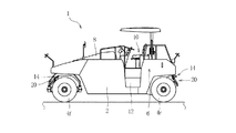
図1に示す転圧ローラ車両1は、車体2を備える。この車体2は、その前後に車輪を兼用するフロント及びリア転圧ローラ4をそれぞれ有しており、具体的には、フロント転圧ローラ4fは3つ、リア転圧ローラ4rは4つあって、これらは車体2の幅方向に並んでいる。また、車体2の上部中央には運転席10が配置されており、この運転席10に対しては車体2の側部のステップ12を利用して登り降りすることができる。
Hereinafter, a rolling roller vehicle as a rolling machine will be described with reference to the drawings.
A
また、車体2の後部には燃料タンク及び作動油タンクから構成されるタンク装置6が設けられている一方、車体2の前部にはエンジンルーム8が設けられており、このエンジンルーム8内にはエンジン(図示しない)が配置されている。このエンジンルーム8内にはエンジン近傍に油圧ポンプ(図示しない)もまた配置されており、この油圧ポンプはエンジンにより駆動され、転圧ローラ4の走行モータ等の油圧機器に向けて、タンク装置6、即ち、作動油タンク内から吸い上げた作動油を供給する。なお、タンク装置6の燃料タンクはエンジンの燃料を蓄えている。
A
また、車体2の前端部及び後端部にはスクレーパ装置20がそれぞれ設けられている。詳しくは、車体2のフロント側にはスクレーパ装置20が1つ配置され、このスクレーパ装置20は3つのフロント転圧ローラ4fに共用される。一方、リア側にはスクレーパ装置20が2つ配置され、各スクレーパ装置20は隣接する2つのリア転圧ローラ4rに共用される。図2はリア側の一方のスクレーパ装置20を示す。
A
以下、リア側のスクレーパ装置20について詳述する。
スクレーパ装置20は、固定ブラケット22を備えている。この固定ブラケット22は、車体2の幅方向に離間した一対の板材を含み、これら板材は2つのリア転圧ローラ4r間を上下方向に平行に延び、且つ互いに連結されている。固定ブラケット22は、その上端が取付板21を介して車体2の下面に取り付けられ、その下端はリア転圧ローラ4rの周面近傍に位置付けられている。なお、取付板21はボルト21bを介して車体2の下面に固定されている。
Hereinafter, the rear-
The
また、上下方向でみて固定ブラケット22の中央部には可動ブラケット24が取り付けられている。この可動ブラケット24は固定ブラケット22を外側から挟み込む一対の板材からなり、これら板材はその基端が連結ピン24bを介して固定ブラケット22に取り付けられる一方、車体2の後方斜め下方に向かって互いに平行に延び、後述するように互いに連結されている。それ故、可動ブラケット24はその基端部、即ち、連結ピン24bを中心に回動可能である。
A
更に、スクレーパ装置20は可動ブラケット24の回動を制限するストッパ機構を備えている。詳しくは、このストッパ機構は、可動ブラケット24の板材間に掛け渡されたロッド36と、固定ブラケット22の下端部から可動ブラケット24内を車体2の後方に向かって延びる回動可能な支持ステー34とを備えている。支持ステー34はその先端にU字型の凹部を有し、この凹部はロッド36と係合可能である。それ故、可動ブラケット24の下方への回動は支持ステー34の凹部にロッド36を係合させることで制限される。
Furthermore, the
また、固定ブラケット22の一方の板材にはその後面にロッド状のストッパ38が取り付けられており、このストッパ38は連結ピン24bの近傍に位置し、車体2の幅方向に延びている。具体的には、ストッパ38は可動ブラケット24の回動中心、即ち、連結ピン24bよりやや上方に位置付けられ、その周面にて可動ブラケット24の一方の板材の上面と当接可能である。また、固定ブラケット22の下端部と可動ブラケット24の他方の板材とは、引っ張りコイルばね32を介して接続されている。この引っ張りコイルばね32の両端は固定及び可動ブラケット22、24の板材から内方に突出した突起30にそれぞれ掛止され、可動ブラケット22を下方に向けて回動付勢している。それ故、可動ブラケット24がストッパ38に当接するまで上方に向けて回動されたとき、支持ステー34の凹部とロッド36との係合が解除され、この後、支持ステー34を起立させることで、可動ブラケット24は支持ステー34に拘わらず、引っ張りコイルばね32により下方に向けて回動付勢される。
Further, a rod-
一方、可動ブラケット24の先端部にはその下面に取付ブラケット25が取り付けられており、この取付ブラケット25は、スクレーパ装置20に対応する2つのリア転圧ローラ4rに跨って延びている。一方、可動ブラケット24の先端部にはその上側には取手28が設けられている。この取手28は車体2の幅方向に延びる水平な握り部位と、この握り部位の両端から延びる一対の脚部位とからなるコ字形状をなし、これら脚部位はそれぞれ可動ブラケット24の対応する板材の内面に固定される一方、握り部位は可動ブラケット24の上縁から車体2の後方に向かって若干突出している。
On the other hand, a mounting
更に、取付ブラケット25の両端にはロッドからなる矩形の保持枠26がそれぞれ設けられており、これら保持枠26はリア転圧ローラ4rの幅方向に延びている。保持枠26内にはリブ27が配置され、リブ27は保持枠26内をリア転圧ローラ4rの幅方向に並び且つその周面に対向する2つの開口部に区画している。
Further, a
そして、この保持枠26にはスクレーパとしての矩形のブラシマット40が取り付けられている。このブラシマット40は、ココヤシの繊維を編み込んだ繊維シートを袋状に形成したものである。詳しくは、ブラシマット40は、リア転圧ローラ4rの幅方向に亘って延びる長手軸線を有し且つこの長手軸線方向の一端にて開口した開口端を有する。この開口端は保持枠26を受け入れ可能な大きさを有している。それ故、保持枠26がブラシマット40内に受け入れられ、保持枠26とブラシマット40とが結束バンド42により互いに締結されることで、ブラシマット40は保持枠26に取り外し可能に保持されている。また、前述の説明から明らかなように、支持ステー34に対する可動ブラケット24の係合が解除されることで、ブラシマット40は引っ張りコイルばね32の付勢力を受け、リア転圧ローラ4rの周面に対して当接可能である。
A
具体的には、図3に示すように、ブラシマット40は保持枠26に保持された際、保持枠26の下方を覆う領域、即ち、リア転圧ローラ4rの周面を摺接させる使用部位40aと、保持枠26の上方を覆う領域、即ち、使用部位40a以外の固定部位40fとに分けられる。そして、結束バンド42の一端はブラシマット40の固定部位40fの上方から貫通して保持枠26に巻き付けられた後、再度固定部位40fの下方から上方に貫通してブラシマット40の上方に引き出され、他端に結び付けられ、これにより、ブラシマット40は結束バンド42を介して保持枠26に固定されている。つまり、ブラシマット40の使用部位40aに結束バンド42が露出することはない。なお、結束バンド42は保持枠26の長手軸線を挟む両側に4箇所ずつ配置され、更にブラシマット40及びリブ27もまた1つの結束バンド42より同様にして結束されている(図2参照)。
Specifically, as shown in FIG. 3, when the
更に、転圧ローラ車両には散水装置14が設けられており、この散水装置14は、溶剤及び水の供給配管としての一対のパイプ16を備えている。これらパイプ16はスクレーパ装置20の近傍を車体2の幅方向に互いに平行に延び、取付具17を介して車体2に支持されている。
詳しくは、取付具17は車体2の後端部にボルト17bを介して取り付けられた取付板17aと、この取付板17aに対してパイプ16を押さえ付ける押さえ片19とからなり、これら押さえ片19はボルト19bにより取付板17aに固定されている。パイプ16のそれぞれにはリア転圧ローラ4rの周面に向けて噴出ノズル18が配置されており、これら噴出ノズル18はリア転圧ローラ4rの周面に溶剤又は水を噴出する。なお、この散水装置14の噴出ノズルはフロント側のスクレーパ装置20の近傍にも同様にして設けられていることは言うまでもない。
Further, the rolling roller vehicle is provided with a watering
Specifically, the
前述したように可動ブラケット24のロッド36が支持ステー34に係合されているとき、スクレーパ装置20は休止位置にあって、そのブラシマット40は対応するリア転圧ローラ4rの周面から上方に離間している。この状態から、オペレータが取手28を掴み、可動ブラケット24を引っ張りコイルばね32の付勢力に抗して上方に一旦回動させ、ロッド36の係合を解除すれば、可動ブラケット24は引っ張りコイルばね32の付勢力を受けて、下方に回動され、これにより、スクレーパ装置20はブラシマット40がリア転圧ローラ4rの周面に当接した作業位置となる。
As described above, when the
それ故、転圧ローラ車両1の転圧作業中、ブラシマット40の使用部位40aにリア転圧ローラ4rの周面が摺接する一方、散水装置14の噴出ノズル18からリア転圧ローラ4rの周面に噴出される溶剤又は水により、リア転圧ローラ4rの周面に付着した付着物が除去される。
このような転圧作業において、ブラシマット40の使用部位40aが摩耗し、その厚さが減少しても、使用部位40aに厚さが残されている限り、結束バンド42や保持枠26等が使用部位40aから露出されることはない。それ故、リア転圧ローラ4rの周面と結束バンド42とが当接することはないので、リア転圧ローラ4rの周面が結束バンド42により傷付けられることもない。また、使用部位40aが摩耗しても、結束バンド42とブラシマット40の固定部位40fとの締結は維持されるから、転圧作業中、ブラシマット40と保持枠26との締結が緩み、ブラシマット40が舗装面上に脱落することはない。
Therefore, during the rolling operation of the rolling
In such a rolling operation, even if the
それ故、ブラシマット40の使用部位40aは有効に転圧作業に使用され、それ故、ブラシマット40の交換サイクルを延ばすことができ、メンテナンス性の向上が図られる。
更に、ブラシマット40は保持枠26の受け入れを許容する袋状をなし、しかも、結束バンド42により保持枠26に結び付けられているだけであるので、保持枠26に対するブラシマット40の装着は容易である。
Therefore, the
Furthermore, since the
以上で本発明の一実施形態についての説明を終えるが、本発明は上記実施形態に限定されるものではなく、本発明の実施形態を逸脱しない範囲で種々の変更ができる。
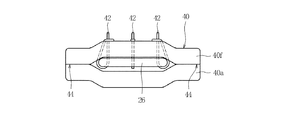
例えば、図4及び図5に示すように、ブラシマット40は、その使用部位40a及び固定部位40fが長手軸線を挟む両側縁44のみにて貼り合わされ、両端の何れからでも、保持枠26を受け入れ可能としたものであってもよい。更に、この場合、使用部位40a及び固定部位40fは別の材料から形成されていてもよい。
The description of one embodiment of the present invention is finished as above, but the present invention is not limited to the above embodiment, and various modifications can be made without departing from the embodiment of the present invention.
For example, as shown in FIGS. 4 and 5, the
また、図6に示すように、ブラシマット40は1枚のシート状であってもよい。この場合、ブラシマット40は、転圧ローラ4の周面側の保持枠26の面を覆う使用部位40aと、保持枠26の長手軸線を挟んだ両側部を包み込む固定部位40fとを有し、これら固定部位40fが結束バンド42を介して保持枠26に結び付けられることで、ブラシマット40は保持枠26に装着されている。
Further, as shown in FIG. 6, the
1 転圧ローラ車両
2 車体
4 転圧ローラ(車輪)
6 タンク装置
8 エンジンルーム
10 運転席
12 ステップ
14 散水装置
16 パイプ
17 取付具
17a 取付板
17b ボルト
18 噴出ノズル
19 押さえ片
19b ボルト
20 スクレーパ装置
21 取付板
21b ボルト
22 固定ブラケット
24 可動ブラケット
24b 連結ピン
25 取付ブラケット
26 保持枠(枠部材)
27 リブ
28 取手
30 突起
32 引っ張りコイルばね
34 支持ステー
36 ロッド
38 ストッパ
40 ブラシマット(スクレーパ)
40a 使用部位
40f 固定部位
42 結束バンド
44 両側縁
1
6 Tank device 8
27
Claims (4)
前記車体の前後に配置され、車輪を兼用する転圧ローラと、
前記転圧ローラの周面の付着物を除去するスクレーパ装置と
を備え、
前記スクレーパ装置は、
前記車体から延び、上下方向に回動可能で、先端に枠部材を有した可動ブラケットと、
前記枠部材に脱着可能に装着され、前記可動ブラケットの回動操作を受けて前記転圧ローラの周面を摺接させるスクレーパと
を含み、
前記スクレーパは、前記転圧ローラの周面に対向する側の前記枠部材の全域を覆う使用部位と、この使用部位との間に前記枠部材を挟み込み、前記枠部材に結合具を介して結合される固定部位とを有することを特徴とする転圧機械。 The car body,
A rolling roller disposed before and after the vehicle body and also serving as a wheel;
A scraper device for removing deposits on the circumferential surface of the rolling roller,
The scraper device
A movable bracket extending from the vehicle body, rotatable in the vertical direction, and having a frame member at a tip;
A scraper that is detachably attached to the frame member and receives a turning operation of the movable bracket to slidably contact the peripheral surface of the rolling roller;
The scraper sandwiches the frame member between a use part that covers the entire area of the frame member on the side facing the peripheral surface of the rolling roller, and is coupled to the frame member via a coupler. And a fixed part to be pressed.
The rolling device according to any one of claims 1 to 3, wherein the coupler is a binding band that penetrates the fixing portion and can be wound around the frame member.
Priority Applications (1)
| Application Number | Priority Date | Filing Date | Title |
|---|---|---|---|
| JP2010153876A JP5296017B2 (en) | 2010-07-06 | 2010-07-06 | Rolling machine |
Applications Claiming Priority (1)
| Application Number | Priority Date | Filing Date | Title |
|---|---|---|---|
| JP2010153876A JP5296017B2 (en) | 2010-07-06 | 2010-07-06 | Rolling machine |
Publications (2)
| Publication Number | Publication Date |
|---|---|
| JP2012017560A true JP2012017560A (en) | 2012-01-26 |
| JP5296017B2 JP5296017B2 (en) | 2013-09-25 |
Family
ID=45603002
Family Applications (1)
| Application Number | Title | Priority Date | Filing Date |
|---|---|---|---|
| JP2010153876A Expired - Fee Related JP5296017B2 (en) | 2010-07-06 | 2010-07-06 | Rolling machine |
Country Status (1)
| Country | Link |
|---|---|
| JP (1) | JP5296017B2 (en) |
Cited By (3)
| Publication number | Priority date | Publication date | Assignee | Title |
|---|---|---|---|---|
| WO2014033886A1 (en) | 2012-08-30 | 2014-03-06 | 富士通株式会社 | Image processing apparatus, image processing method, and program |
| JP2015200132A (en) * | 2014-04-09 | 2015-11-12 | 日立建機株式会社 | Sliding contact device for tire |
| JP2021055301A (en) * | 2019-09-27 | 2021-04-08 | 日立建機株式会社 | Rolling compaction vehicle |
Citations (6)
| Publication number | Priority date | Publication date | Assignee | Title |
|---|---|---|---|---|
| JPS5197204A (en) * | 1975-01-17 | 1976-08-26 | ||
| JPH06197855A (en) * | 1992-11-11 | 1994-07-19 | Shimomura Komuten:Kk | Cleaning unit |
| JPH079951A (en) * | 1993-06-22 | 1995-01-13 | Sakai Jukogyo Kk | Slide-contact body fitting structure for slide-contact device for tire |
| JPH1086798A (en) * | 1996-09-19 | 1998-04-07 | Sakai Heavy Ind Ltd | Mud-guard device of rolling compaction machine |
| JPH11146857A (en) * | 1997-11-18 | 1999-06-02 | Hiroto Okuma | Fibrous mop containing bleacher and fiber knitting and weaving body for mop |
| JP2001131906A (en) * | 1999-11-08 | 2001-05-15 | Sakai Heavy Ind Ltd | Sliding contact device for rolling compaction wheel of rolling compaction vehicle |
-
2010
- 2010-07-06 JP JP2010153876A patent/JP5296017B2/en not_active Expired - Fee Related
Patent Citations (6)
| Publication number | Priority date | Publication date | Assignee | Title |
|---|---|---|---|---|
| JPS5197204A (en) * | 1975-01-17 | 1976-08-26 | ||
| JPH06197855A (en) * | 1992-11-11 | 1994-07-19 | Shimomura Komuten:Kk | Cleaning unit |
| JPH079951A (en) * | 1993-06-22 | 1995-01-13 | Sakai Jukogyo Kk | Slide-contact body fitting structure for slide-contact device for tire |
| JPH1086798A (en) * | 1996-09-19 | 1998-04-07 | Sakai Heavy Ind Ltd | Mud-guard device of rolling compaction machine |
| JPH11146857A (en) * | 1997-11-18 | 1999-06-02 | Hiroto Okuma | Fibrous mop containing bleacher and fiber knitting and weaving body for mop |
| JP2001131906A (en) * | 1999-11-08 | 2001-05-15 | Sakai Heavy Ind Ltd | Sliding contact device for rolling compaction wheel of rolling compaction vehicle |
Cited By (4)
| Publication number | Priority date | Publication date | Assignee | Title |
|---|---|---|---|---|
| WO2014033886A1 (en) | 2012-08-30 | 2014-03-06 | 富士通株式会社 | Image processing apparatus, image processing method, and program |
| JP2015200132A (en) * | 2014-04-09 | 2015-11-12 | 日立建機株式会社 | Sliding contact device for tire |
| JP2021055301A (en) * | 2019-09-27 | 2021-04-08 | 日立建機株式会社 | Rolling compaction vehicle |
| JP7130612B2 (en) | 2019-09-27 | 2022-09-05 | 日立建機株式会社 | Compaction vehicle |
Also Published As
| Publication number | Publication date |
|---|---|
| JP5296017B2 (en) | 2013-09-25 |
Similar Documents
| Publication | Publication Date | Title |
|---|---|---|
| JP5296017B2 (en) | Rolling machine | |
| WO2011030545A1 (en) | Device for taking up fire-fighting hose and method for taking up fire-fighting hose using same | |
| KR20100121627A (en) | Method and apparatus for removing a film from a surface | |
| DE102010003756A1 (en) | cleaner | |
| WO2014145881A1 (en) | Cleaning apparatus | |
| JP5555027B2 (en) | Method and apparatus for cleaning the floor | |
| JP6675128B1 (en) | High pressure water cleaning device for fishing net and method of cleaning fishing net | |
| CN110170820A (en) | A kind of pressure pin device | |
| US8727245B2 (en) | Pressure washer wand edger | |
| JP2014100710A (en) | Base conditioning method of power transmission steel tower, scattering prevention method, and scattering prevention device | |
| JP5497674B2 (en) | Rolling machine | |
| CN101779941A (en) | Strip mop with mechanical wiping device | |
| KR19980046193U (en) | Filter cloth cleaning device of filter press filtration plate | |
| JP6537238B2 (en) | Concrete formwork structure | |
| CN110369347A (en) | A kind of washer suitable for cleaning air conditioner louver and waffle slab | |
| US20100313367A1 (en) | Cleaning apparatus with quickly replaceable cleaning head | |
| US8894469B2 (en) | Sanding machine with clamping mechanism | |
| CN210754009U (en) | Water hose cleaning machine | |
| CN208679895U (en) | A kind of slewing rollers wiping roller mechanism | |
| CN210043941U (en) | Folding mop placing structure of floor washing vehicle | |
| CN219341102U (en) | Fire hose washs coiling mechanism | |
| KR200495884Y1 (en) | Self assembly handle type water gummed tape dispenser | |
| KR102482250B1 (en) | Crop recovery device | |
| KR101524082B1 (en) | a ridge vinyl cover structure | |
| CN217994903U (en) | Pipe packing device based on packing belt |
Legal Events
| Date | Code | Title | Description |
|---|---|---|---|
| A621 | Written request for application examination |
Free format text: JAPANESE INTERMEDIATE CODE: A621 Effective date: 20120810 |
|
| A977 | Report on retrieval |
Free format text: JAPANESE INTERMEDIATE CODE: A971007 Effective date: 20130515 |
|
| TRDD | Decision of grant or rejection written | ||
| A01 | Written decision to grant a patent or to grant a registration (utility model) |
Free format text: JAPANESE INTERMEDIATE CODE: A01 Effective date: 20130529 |
|
| A61 | First payment of annual fees (during grant procedure) |
Free format text: JAPANESE INTERMEDIATE CODE: A61 Effective date: 20130612 |
|
| R150 | Certificate of patent or registration of utility model |
Ref document number: 5296017 Country of ref document: JP Free format text: JAPANESE INTERMEDIATE CODE: R150 Free format text: JAPANESE INTERMEDIATE CODE: R150 |
|
| LAPS | Cancellation because of no payment of annual fees |