US8894469B2 - Sanding machine with clamping mechanism - Google Patents
Sanding machine with clamping mechanism Download PDFInfo
- Publication number
- US8894469B2 US8894469B2 US12/845,922 US84592210A US8894469B2 US 8894469 B2 US8894469 B2 US 8894469B2 US 84592210 A US84592210 A US 84592210A US 8894469 B2 US8894469 B2 US 8894469B2
- Authority
- US
- United States
- Prior art keywords
- clamping
- bottom plate
- tensioning
- burnishing
- area
- Prior art date
- Legal status (The legal status is an assumption and is not a legal conclusion. Google has not performed a legal analysis and makes no representation as to the accuracy of the status listed.)
- Expired - Fee Related, expires
Links
Images


Classifications
-
- B—PERFORMING OPERATIONS; TRANSPORTING
- B24—GRINDING; POLISHING
- B24B—MACHINES, DEVICES, OR PROCESSES FOR GRINDING OR POLISHING; DRESSING OR CONDITIONING OF ABRADING SURFACES; FEEDING OF GRINDING, POLISHING, OR LAPPING AGENTS
- B24B23/00—Portable grinding machines, e.g. hand-guided; Accessories therefor
- B24B23/04—Portable grinding machines, e.g. hand-guided; Accessories therefor with oscillating grinding tools; Accessories therefor
-
- B—PERFORMING OPERATIONS; TRANSPORTING
- B24—GRINDING; POLISHING
- B24D—TOOLS FOR GRINDING, BUFFING OR SHARPENING
- B24D15/00—Hand tools or other devices for non-rotary grinding, polishing, or stropping
- B24D15/02—Hand tools or other devices for non-rotary grinding, polishing, or stropping rigid; with rigidly-supported operative surface
- B24D15/023—Hand tools or other devices for non-rotary grinding, polishing, or stropping rigid; with rigidly-supported operative surface using in exchangeable arrangement a layer of flexible material
Definitions
- the following generally relates to sanding machines and, more particularly, relates to a sanding machine having a mechanism for clamping a burnishing element such as sand paper.
- Sanding machines are power tools which are commonly used to burnish the surface of a workpiece, particularly to make the surface smooth and even.
- a sanding machine comprises a housing and a bottom plate mounted thereunder.
- a motor is arranged in the housing and drives the bottom plate to move via a transmission mechanism. Both ends of the bottom plate are arranged with a clamping mechanism.
- a burnishing element such as a sand paper, could be supported on the lower surface of the bottom plate where the sand paper is clamped by the two clamping mechanisms respectively positioned on both ends of the bottom plate.
- the sand paper can be moved along with the bottom plate so as to burnish the surface of the workpiece.
- U.S. Pat. No. 6,857,948 discloses this kind of the clamping mechanism, which is mounted on one end of the bottom plate and comprises an active jaw and a passive jaw. Both the active jaw and the passive jaw are pivotable together about a shaft in the end of the bottom plate.
- one end of the sand paper is clamped firstly.
- the other end of the sand paper is put into the clearance between the active jaw and the passive jaw.
- the active jaw is pivoted to make it close toward the passive jaw so as to clamp the ends of the sand paper between the active and passive jaws.
- the passive jaw With a further pivoting of the active jaw, it will drive the passive jaw to pivot together.
- the end of the sand paper clamped between the two jaws will pivot about the shaft along with the jaws so that it moves away from the other end of the sand paper and is tensioned.
- the above sand paper clamping mechanism adds a tensioning function it still suffers from at least one defect.
- the active and passive jaws of the above clamping mechanism are both mounted on the bottom plate in a movable manner, the vibration of the machine will cause the active and passive jaws to move, so that the clamping and tensioning force between the two jaws is weakened, thus resulting in the clamping and tensioning of the sand paper being unreliable.
- the following describes a sanding machine that overcomes the defects existing in the above prior art by providing a clamping mechanism whereby a burnishing element could be clamped and tensioned by the clamping mechanism in a more reliable manner.
- the sanding machine described hereinafter comprises a housing and a bottom plate mounted thereunder.
- a burnishing element can be supported on the lower surface of the bottom plate, and the two ends of the bottom plate are mounted with a first clamping mechanism and a second clamping mechanism for clamping the burnishing element respectively, wherein at least one of the first and second clamping mechanisms comprises a clamping element and a tensioning element used for tensioning the burnishing element.
- the bottom plate includes a clamping area, and the ends of the tensioned burnishing element are supported on the clamping area when the burnishing element is in a tensioned condition.
- the clamping element and the tensioning element each performs its own function and acts respectively with the clamping area of the bottom plate to implement the clamping and the tensioning.
- the ends of the burnishing element are pressed tightly on the lower surface of the clamping area by the clamping element and the tensioning element. Due to the clamping area being a rigid element, the clamping area will not be moved by the vibration of the machine during the working of the sanding machine so as to make the clamping and tensioning of the burnishing element more reliable.
- FIG. 1 is a schematic view of an exemplary sanding machine constructed according to the description that follows;
- FIG. 2 is a schematic view of the bottom plate of the sanding machine of FIG. 1 particularly showing the first end and second end clamping mechanisms;
- FIG. 3 is a schematic view of the bottom plate of FIG. 2 , with the clamping mechanism removed;
- FIG. 4 is a schematic view of the second end clamping mechanism of FIG. 2 ;
- FIG. 5 is a schematic view illustrating the clamping mechanism of FIG. 2 in a clamping position
- FIG. 6 is a bottom view of the bottom plate of FIG. 3 ;
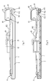
- FIG. 7 is a schematic view illustrating the clamping mechanism of FIG. 2 in a clamping and tensioning position
- FIG. 8 is a sectional view of the clamping mechanism as shown in FIG. 7 .
- a sanding machine 10 comprises a housing 1 and a bottom plate 2 mounted thereunder.
- a grasping portion or handle 11 is formed on the housing 1 and a dust outlet 12 is connected to the back lower portion of the housing 1 .
- a motor (not shown) is mounted in the housing 1 and drives the bottom plate 2 to move via a power transmission mechanism.
- the first end 21 and the second end 22 of the bottom plate 2 are mounted with a first clamping mechanism 6 and a second clamping mechanism 8 respectively.
- a burnishing element 4 such as a sand paper, can be supported on the lower surface of the bottom plate 2 and both ends of the sand paper are clamped in the first and the second clamping mechanisms 6 and 8 , respectively.
- the sand paper 4 moves together with the bottom plate 2 so as to burnish the surface of the workpiece.
- the first clamping mechanism 6 is a traditional clamping mechanism which is basically formed by a bent steel wire.
- the first clamping mechanism 6 comprises a first clamping portion 61 , a first handle 62 , and two first mounting portions 63 in the same line.
- the two first mounting portions 63 can be mounted into the bore 23 and the groove 24 in the first end 21 of the bottom plate, respectively, and fixed by the bolt 31 and the stop plate 32 so that the first clamping mechanism 6 is mounted onto the bottom plate 2 .
- a first pivot axis 64 is formed by the two first supporting portions 63 .
- the handle 62 is pivotable about the first pivot axis 64 between the clamping and releasing positions so as to drive the first clamping portion 61 to clamp or release the sand paper.
- the first clamping mechanism 6 is in the releasing condition, i.e., there is a clearance between the first clamping portion 61 and the first end 21 of the bottom plate and one end of the sand paper 4 could be inserted thereinto.
- the first clamping mechanism 6 is in the clamping condition, i.e., the first handle 62 is pivoted about the first pivot axis 64 to the position adjacent to the first locking block 25 on the bottom plate 2 where a first locking block 25 could maintain the first handle 62 in the clamping position.
- the second clamping mechanism 8 comprises a clamping element 81 and a tensioning element 82 .
- the tensioning element 82 is basically formed by a bent steel wire and the clamping element 81 is basically formed by a bent steel spring plate.
- the clamping element 81 is connected to the tensioning element 82 by two rivets 83 . In other embodiments, the clamping element 81 could also be replaced by other materials having some flexibility.
- the tensioning element 82 comprises a tensioning portion 821 , a second handle 822 and two second mounting portions 823 in the same line.
- the clamping element 81 comprises a second clamping portion 811 located outside of the tensioning portion 821 .
- a rubber strip 812 is mounted on the second clamping portion 811 for contacting with the sand paper 4 . In the clamping condition, the rubber strip 812 is pressed tightly on one end of the sand paper 4 .
- the two second mounting portions 823 could be located in the two grooves 26 in the second end 22 of the bottom plate, respectively, and fixed by two bolts 33 , so that the second clamping mechanism 8 is mounted on the bottom plate 2 .
- a second pivot shaft axis 84 is formed by the two second mounting portions 823 together.
- the second handle 822 is pivotable about the second pivot shaft axis 84 to thereby drive the clamping element 81 and tensioning element 82 about the second pivot shaft axis 84 together between the clamping position and the releasing position.
- the bottom plate 2 is arranged with a second locking block 29 thereon for maintaining the second handle 822 in the clamping position.
- the second end 22 of the bottom plate 2 is arranged with a clamping area 20 extending outwardly.
- the lower surface of the clamping area 20 is above the lower surface of the bottom plate 2 .
- the clamping area 20 is arranged with a release-proof mechanism on its lower surface, which is a long-strip shaped projection 27 for preventing the clamped sand paper from releasing.
- the clamping area 20 and the bottom plate 2 are formed integrally, while in other embodiments, the clamping area could also be a separate part which is connected to the bottom plate by a connection component.
- one end of the sand paper 4 is put into the clearance that is between the first clamping portion 61 of the first clamping mechanism 6 and the first end 21 of the bottom plate firstly.
- the first handle 62 is pivoted about the first pivot shaft axis 64 so as to drive the first clamping portion 61 to pivot about the first pivot shaft axis 64 , so that the end of the sand paper is clamped on the bottom plate 2 .
- the first handle 62 is pivoted to the position adjacent to the first locking block 25 and maintained in this position, i.e. the condition shown in FIG. 5 .
- the end of the sand paper 4 When the other end of the sand paper 4 is clamped, the end of the sand paper firstly passes over the projection 27 and is inserted into the clearance between the second clamping portion 811 and the clamping area 20 of the bottom plate.
- the second handle 822 is pivoted about the second pivot shaft 84 , and accordingly, the clamping element 81 and the tensioning element 82 are driven together to pivot about the second pivot shaft axis 84 .
- the rubber strip 812 on the clamping element 81 contacts with the end of the sand paper firstly and presses it on the lower surface of the clamping area 20 so as to clamp the end of the sand paper.
- the tensioning element 82 With the second handle 822 being further pivoted, the clamping force applied by the clamping element 81 on the end of the sand paper is increased. At the same time, the tensioning element 82 continues to move about the second pivot shaft axis 84 along an arcuate track A. The tensioning portion 821 of the tensioning element 82 contacts with the sand paper and pulls the sand paper upwardly and inclinedly. When the tensioning portion 821 is pivoted until it is stopped by the clamping area 20 , the sand paper 4 is tensioned and the second handle 822 is engaged with the second locking block 29 , in the tensioning condition as shown in FIGS. 7 and 8 .
- the tensioned end of the sand paper is located between the second clamping portion 811 and the clamping area 20 , and at the same time between the tensioning portion 821 and the clamping area 20 . Because the clamping area 20 has no relative movement with the bottom plate 2 therebetween and has no elasticity, the vibration generated by the sanding machine during working will not cause the movement of the clamping area 20 , which makes the clamping and tensioning of the sand paper more reliable. Additionally, the projection 27 on the clamping area 20 is located between the second clamping portion 811 and the tensioning portion 821 in the tensioning condition of the sand paper, which will prevent the tensioned sand paper from moving toward the other end of the sand paper.
- the sanding machine disclosed by the present invention is not limited by the contents described above and the structure shown in the drawings.
- the release-proof mechanism on the lower surface of the clamping area of the bottom plate could also be implemented by designing the lower surface of the clamping area as a tooth surface.
Abstract
Description
Claims (8)
Applications Claiming Priority (3)
| Application Number | Priority Date | Filing Date | Title |
|---|---|---|---|
| CN 200920234018 CN201493733U (en) | 2009-08-03 | 2009-08-03 | Sanding machine |
| CN200920234018U | 2009-08-03 | ||
| CN200920234018.2 | 2009-08-03 |
Publications (2)
| Publication Number | Publication Date |
|---|---|
| US20110028076A1 US20110028076A1 (en) | 2011-02-03 |
| US8894469B2 true US8894469B2 (en) | 2014-11-25 |
Family
ID=42436942
Family Applications (1)
| Application Number | Title | Priority Date | Filing Date |
|---|---|---|---|
| US12/845,922 Expired - Fee Related US8894469B2 (en) | 2009-08-03 | 2010-07-29 | Sanding machine with clamping mechanism |
Country Status (6)
| Country | Link |
|---|---|
| US (1) | US8894469B2 (en) |
| CN (1) | CN201493733U (en) |
| CA (1) | CA2712926A1 (en) |
| DE (1) | DE202010008190U1 (en) |
| FR (1) | FR2948588B3 (en) |
| GB (1) | GB2472498B (en) |
Families Citing this family (3)
| Publication number | Priority date | Publication date | Assignee | Title |
|---|---|---|---|---|
| CN201493733U (en) | 2009-08-03 | 2010-06-02 | 南京德朔实业有限公司 | Sanding machine |
| CN106141842B (en) * | 2015-04-16 | 2019-08-20 | 苏州宝时得电动工具有限公司 | Flat sanding machine bottom deck assembly and flat sanding machine |
| CN218363903U (en) * | 2021-10-01 | 2023-01-24 | 创科无线普通合伙 | Base for sheet type sander |
Citations (19)
| Publication number | Priority date | Publication date | Assignee | Title |
|---|---|---|---|---|
| US2242545A (en) * | 1940-03-27 | 1941-05-20 | Sundstrand Machine Tool Co | Rubbing machine |
| US2282043A (en) * | 1939-11-08 | 1942-05-05 | Sundstrand Machine Tool Co | Rubbing machine |
| US2475476A (en) * | 1945-01-25 | 1949-07-05 | Roy J Champayne | Rubbing shoe |
| US2546087A (en) | 1949-04-11 | 1951-03-20 | Arthur C Burleigh | Pad element for abrading machines |
| US2712206A (en) * | 1952-06-16 | 1955-07-05 | Roy J Champayne | Rubbing shoe |
| US2749679A (en) * | 1953-11-25 | 1956-06-12 | Nicholas T Anton | Shoes for rubbing devices |
| US2848850A (en) * | 1956-08-10 | 1958-08-26 | Rotex Company | Electric sanders |
| US4077165A (en) * | 1976-11-26 | 1978-03-07 | Hutchins Alma A | Abrading tool clip with automatic take-up |
| US4475317A (en) | 1983-11-28 | 1984-10-09 | The Singer Company | Paper retainer for a sanding device |
| GB2322582A (en) | 1997-02-27 | 1998-09-02 | Bosch Gmbh Robert | Electric hand tool |
| US20010039696A1 (en) * | 2000-05-11 | 2001-11-15 | Wieslaw Maciejczyk | Webbing length adjustor |
| US20030019080A1 (en) * | 2001-07-26 | 2003-01-30 | Anthony James R. | Web adjuster device |
| DE10253006A1 (en) | 2002-11-14 | 2004-05-27 | Robert Bosch Gmbh | Powered hand grinder used e.g. as a vibrating sander comprises a grinding plate, and a clamping device having a clamping surface and a removable clamping clip with a manual actuating element |
| US6857948B2 (en) | 2001-08-10 | 2005-02-22 | Robert Bosch Gmbh | Abrasive strip carrier and hand sander |
| US20050085172A1 (en) * | 2002-07-16 | 2005-04-21 | Eduard Gansel | Manual sanding machine tool |
| GB2402095B (en) | 2003-05-26 | 2006-06-14 | Bosch Gmbh Robert | Grinding hand tool machine |
| US20060172670A1 (en) | 2003-11-17 | 2006-08-03 | Juszti Gyoergy | Hand sanding tool |
| US20060246830A1 (en) | 2005-04-29 | 2006-11-02 | 3M Innovative Properties Company | Sanding tool |
| US20080214098A1 (en) * | 2006-08-02 | 2008-09-04 | Carsten Prause | Power Sander With Novel Sanding Sheet Tension Clamping |
Family Cites Families (2)
| Publication number | Priority date | Publication date | Assignee | Title |
|---|---|---|---|---|
| US8141089B2 (en) * | 2007-01-11 | 2012-03-20 | International Business Machines Corporation | Method and apparatus for reducing contention for computer system resources using soft locks |
| CN201493733U (en) | 2009-08-03 | 2010-06-02 | 南京德朔实业有限公司 | Sanding machine |
-
2009
- 2009-08-03 CN CN 200920234018 patent/CN201493733U/en not_active Expired - Fee Related
-
2010
- 2010-07-29 GB GB201012778A patent/GB2472498B/en not_active Expired - Fee Related
- 2010-07-29 US US12/845,922 patent/US8894469B2/en not_active Expired - Fee Related
- 2010-07-30 DE DE201020008190 patent/DE202010008190U1/en not_active Expired - Lifetime
- 2010-07-30 CA CA 2712926 patent/CA2712926A1/en not_active Abandoned
- 2010-08-02 FR FR1056368A patent/FR2948588B3/en not_active Expired - Lifetime
Patent Citations (19)
| Publication number | Priority date | Publication date | Assignee | Title |
|---|---|---|---|---|
| US2282043A (en) * | 1939-11-08 | 1942-05-05 | Sundstrand Machine Tool Co | Rubbing machine |
| US2242545A (en) * | 1940-03-27 | 1941-05-20 | Sundstrand Machine Tool Co | Rubbing machine |
| US2475476A (en) * | 1945-01-25 | 1949-07-05 | Roy J Champayne | Rubbing shoe |
| US2546087A (en) | 1949-04-11 | 1951-03-20 | Arthur C Burleigh | Pad element for abrading machines |
| US2712206A (en) * | 1952-06-16 | 1955-07-05 | Roy J Champayne | Rubbing shoe |
| US2749679A (en) * | 1953-11-25 | 1956-06-12 | Nicholas T Anton | Shoes for rubbing devices |
| US2848850A (en) * | 1956-08-10 | 1958-08-26 | Rotex Company | Electric sanders |
| US4077165A (en) * | 1976-11-26 | 1978-03-07 | Hutchins Alma A | Abrading tool clip with automatic take-up |
| US4475317A (en) | 1983-11-28 | 1984-10-09 | The Singer Company | Paper retainer for a sanding device |
| GB2322582A (en) | 1997-02-27 | 1998-09-02 | Bosch Gmbh Robert | Electric hand tool |
| US20010039696A1 (en) * | 2000-05-11 | 2001-11-15 | Wieslaw Maciejczyk | Webbing length adjustor |
| US20030019080A1 (en) * | 2001-07-26 | 2003-01-30 | Anthony James R. | Web adjuster device |
| US6857948B2 (en) | 2001-08-10 | 2005-02-22 | Robert Bosch Gmbh | Abrasive strip carrier and hand sander |
| US20050085172A1 (en) * | 2002-07-16 | 2005-04-21 | Eduard Gansel | Manual sanding machine tool |
| DE10253006A1 (en) | 2002-11-14 | 2004-05-27 | Robert Bosch Gmbh | Powered hand grinder used e.g. as a vibrating sander comprises a grinding plate, and a clamping device having a clamping surface and a removable clamping clip with a manual actuating element |
| GB2402095B (en) | 2003-05-26 | 2006-06-14 | Bosch Gmbh Robert | Grinding hand tool machine |
| US20060172670A1 (en) | 2003-11-17 | 2006-08-03 | Juszti Gyoergy | Hand sanding tool |
| US20060246830A1 (en) | 2005-04-29 | 2006-11-02 | 3M Innovative Properties Company | Sanding tool |
| US20080214098A1 (en) * | 2006-08-02 | 2008-09-04 | Carsten Prause | Power Sander With Novel Sanding Sheet Tension Clamping |
Non-Patent Citations (1)
| Title |
|---|
| English Abstract of DE10253006, Espacenet, Sep. 4, 2012, 2 pgs. |
Also Published As
| Publication number | Publication date |
|---|---|
| FR2948588A3 (en) | 2011-02-04 |
| US20110028076A1 (en) | 2011-02-03 |
| CN201493733U (en) | 2010-06-02 |
| DE202010008190U1 (en) | 2010-12-02 |
| CA2712926A1 (en) | 2011-02-03 |
| GB201012778D0 (en) | 2010-09-15 |
| GB2472498A (en) | 2011-02-09 |
| FR2948588B3 (en) | 2011-07-15 |
| GB2472498B (en) | 2012-12-26 |
Similar Documents
| Publication | Publication Date | Title |
|---|---|---|
| CA2267044C (en) | Strap welding tool with base plate for reducing strap column strength and method therefor | |
| JP4354568B2 (en) | Banding tool and method thereof | |
| EP2731872B1 (en) | Feeding and reversing mechanism for strapping machine | |
| US6626746B2 (en) | Sander with a clamping device | |
| US8894469B2 (en) | Sanding machine with clamping mechanism | |
| CN103072116A (en) | Tool for removing a chisel | |
| DE602007001264D1 (en) | Tire bead release device for tire changing devices | |
| JP5969071B1 (en) | Man conveyor device and tension adjustment method for moving handrail of man conveyor device | |
| CN100522474C (en) | Abrasive strip carrier and hand sander | |
| RU2521551C2 (en) | Grinding tool | |
| EP1088619A3 (en) | Support for mounting a tool on a pipe | |
| KR20000071432A (en) | Strapping tool with improved strap guide and method therefor | |
| CN1241715C (en) | Sanding hand machine tool | |
| JPS61162325A (en) | Device for joining end section of thermoplastic plastic band | |
| JP5461947B2 (en) | Main body vise device in band saw machine | |
| US20030054742A1 (en) | Hand sanding tool | |
| JP4406557B2 (en) | Belt conveyor | |
| KR101887618B1 (en) | A Polishing Apparatus of Band Saw | |
| JP6433780B2 (en) | Elevator flat rope cleaning device | |
| CN100371132C (en) | Manual sanding machine tool | |
| JP2007268673A (en) | Hose band expanding tool | |
| CN218135936U (en) | White automobile body positioning mechanism | |
| USRE26114E (en) | Power strap tensioning tool | |
| JPS6243690Y2 (en) | ||
| CN210499903U (en) | Manual quick clamp |
Legal Events
| Date | Code | Title | Description |
|---|---|---|---|
| AS | Assignment |
Owner name: CHERVON LIMITED, HONG KONG Free format text: ASSIGNMENT OF ASSIGNORS INTEREST;ASSIGNORS:ZHOU, HONGTAO;CHEN, YASHENG;REEL/FRAME:024759/0220 Effective date: 20100728 |
|
| STCF | Information on status: patent grant |
Free format text: PATENTED CASE |
|
| AS | Assignment |
Owner name: CHERVON (HK) LIMITED, HONG KONG Free format text: ASSIGNMENT OF ASSIGNORS INTEREST;ASSIGNOR:CHERVON LIMITED;REEL/FRAME:038333/0750 Effective date: 20160415 |
|
| MAFP | Maintenance fee payment |
Free format text: PAYMENT OF MAINTENANCE FEE, 4TH YEAR, LARGE ENTITY (ORIGINAL EVENT CODE: M1551) Year of fee payment: 4 |
|
| FEPP | Fee payment procedure |
Free format text: MAINTENANCE FEE REMINDER MAILED (ORIGINAL EVENT CODE: REM.); ENTITY STATUS OF PATENT OWNER: LARGE ENTITY |
|
| LAPS | Lapse for failure to pay maintenance fees |
Free format text: PATENT EXPIRED FOR FAILURE TO PAY MAINTENANCE FEES (ORIGINAL EVENT CODE: EXP.); ENTITY STATUS OF PATENT OWNER: LARGE ENTITY |
|
| STCH | Information on status: patent discontinuation |
Free format text: PATENT EXPIRED DUE TO NONPAYMENT OF MAINTENANCE FEES UNDER 37 CFR 1.362 |
|
| FP | Lapsed due to failure to pay maintenance fee |
Effective date: 20221125 |